1
©
www.aoc.com
2022 AOC.All Rights Reserved
®
LCD Monitor
User Manual
CU34V5CW/BK

i
Safety ................................................................................................................................................................................... 1
National Conventions ................................................................................................................................................ 1
Power ........................................................................................................................................................................ 2
Installation ................................................................................................................................................................. 3
Cleaning .................................................................................................................................................................... 4
Other ......................................................................................................................................................................... 5
Setup .................................................................................................................................................................................... 6
Contents in Box ......................................................................................................................................................... 6
Setup Stand & Base .................................................................................................................................................. 7
Adjusting Viewing Angle ............................................................................................................................................ 8
Connecting the Monitor ............................................................................................................................................. 9
Hello webcam ...........................................................................................................................................................11
Wall Mounting.......................................................................................................................................................... 12
AMD FreeSync function (Available for selective models) ....................................................................................... 13
Adaptive-Sync function (Available for selective models) ......................................................................................... 14
Adjusting ............................................................................................................................................................................. 15
Hotkeys ................................................................................................................................................................... 15
OSD Setting ............................................................................................................................................................ 17
Luminance ................................................................................................................................................... 18
Color Setup .................................................................................................................................................. 19
Picture Boost ............................................................................................................................................... 20
OSD Setup ................................................................................................................................................... 21
PIP Setting .................................................................................................................................................. 22
Game Setting ............................................................................................................................................... 23
Extra ............................................................................................................................................................ 25
Exit ............................................................................................................................................................... 26
LED Indicator .......................................................................................................................................................... 27
Troubleshoot ....................................................................................................................................................................... 28
Specication ....................................................................................................................................................................... 29
General Specication .............................................................................................................................................. 29
Preset Display Modes ............................................................................................................................................. 30
Pin Assignments ...................................................................................................................................................... 31
Plug and Play .......................................................................................................................................................... 32
1
Safety
National Conventions
The following subsections describe notational conventions used in this document.
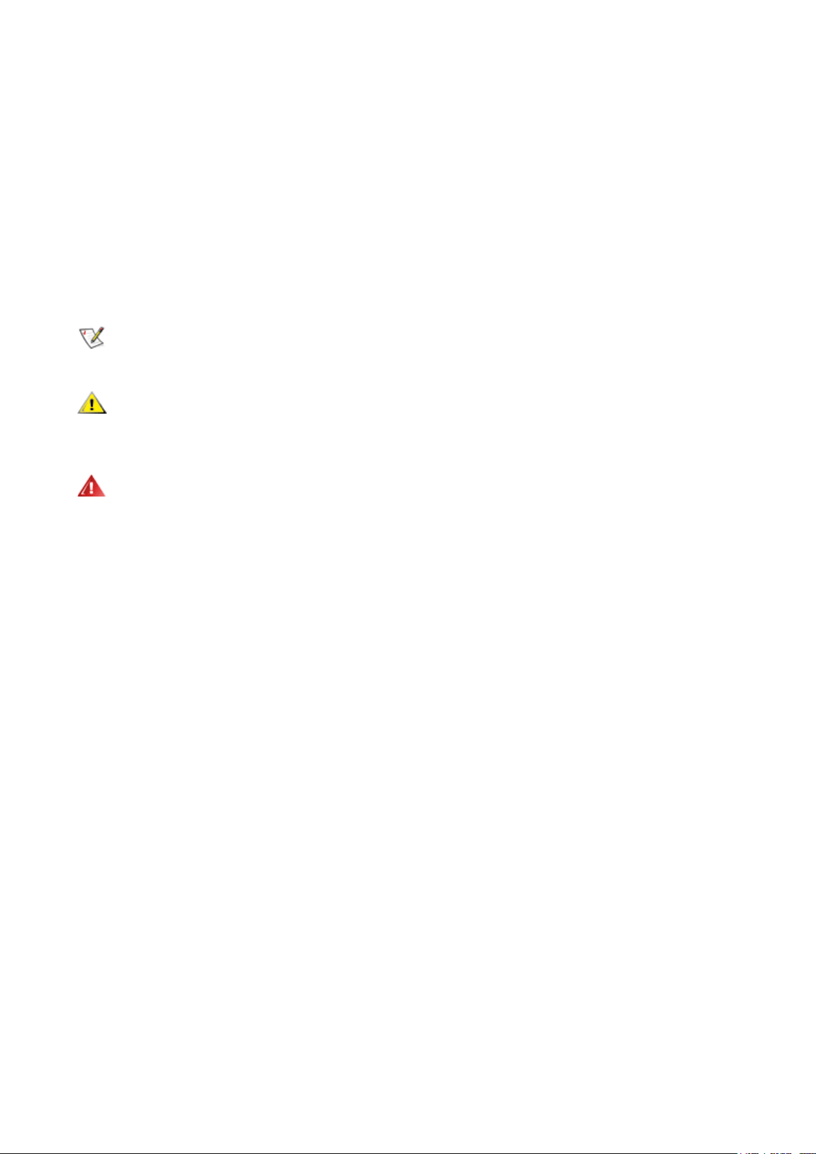
Notes, Cautions, and Warnings
Throughout this guide, blocks of text may be accompanied by an icon and printed in bold type or in italic type. These
blocks are notes, cautions, and warnings, and they are used as follows:
NOTE:
A NOTE indicates important information that helps you make better use of your computer system.
CAUTION:
A CAUTION indicates either potential damage to hardware or loss of data and tells you how to avoid the
problem.
WARNING:
A WARNING indicates the potential for bodily harm and tells you how to avoid the problem. Some warnings
may appear in alternate formats and may be unaccompanied by an icon. In such cases, the specic presentation of the
warning is mandated by regulatory authority.
2
Power
The monitor should be operated only from the type of power source indicated on the label. If you are not sure of the
type of power supplied to your home, consult your dealer or local power company.
The monitor is equipped with a three-pronged grounded plug, a plug with a third (grounding) pin. This plug will t
only into a grounded power outlet as a safety feature. If your outlet does not accommodate the three-wire plug, have an
electrician install the correct outlet, or use an adapter to ground the appliance safely. Do not defeat the safety purpose of
the grounded plug.
Unplug the unit during a lightning storm or when it will not be used for long periods of time. This will protect the
monitor from damage due to power surges.
Do not overload power strips and extension cords. Overloading can result in re or electric shock.
To ensure satisfactory operation, use the monitor only with UL listed computers which have appropriate congured
receptacles marked between 100-240V AC, Min. 5A.
The wall socket shall be installed near the equipment and shall be easily accessible.
3
Installation
Do not place the monitor on an unstable cart, stand, tripod, bracket, or table. If the monitor falls, it can injure a
person and cause serious damage to this product. Use only a cart, stand, tripod, bracket, or table recommended by
the manufacturer or sold with this product. Follow the manufacturer’s instructions when installing the product and use
mounting accessories recommended by the manufacturer. A product and cart combination should be moved with care.
Never push any object into the slot on the monitor cabinet. It could damage circuit parts causing a re or electric
shock. Never spill liquids on the monitor.
Do not place the front of the product on the oor.
If you mount the monitor on a wall or shelf, use a mounting kit approved by the manufacturer and follow the kit
instructions.
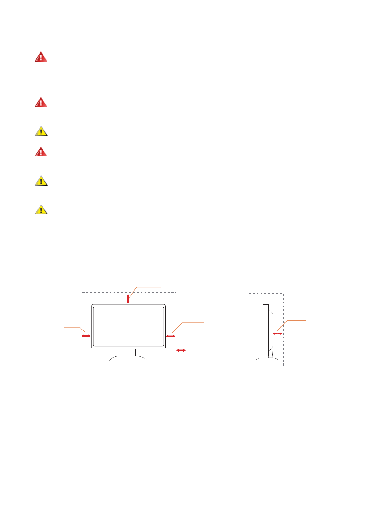
Leave some space around the monitor as shown below. Otherwise, air-circulation may be inadequate hence
overheating may cause a re or damage to the monitor.
To avoid potential damage, for example the panel peeling from the bezel, ensure that the monitor does not tilt
downward by more than -5 degrees. If the -5 degree downward tilt angle maximum is exceeded, the monitor damage will
not be covered under warranty.
See below the recommended ventilation areas around the monitor when the monitor is installed on the wall or on the
stand:
Installed with stand
Installed with stand
12 inches
30cm
4 inches
10cm
4 inches
10cm
4 inches
10cm
Leave at least this much
space around the set
4
Cleaning
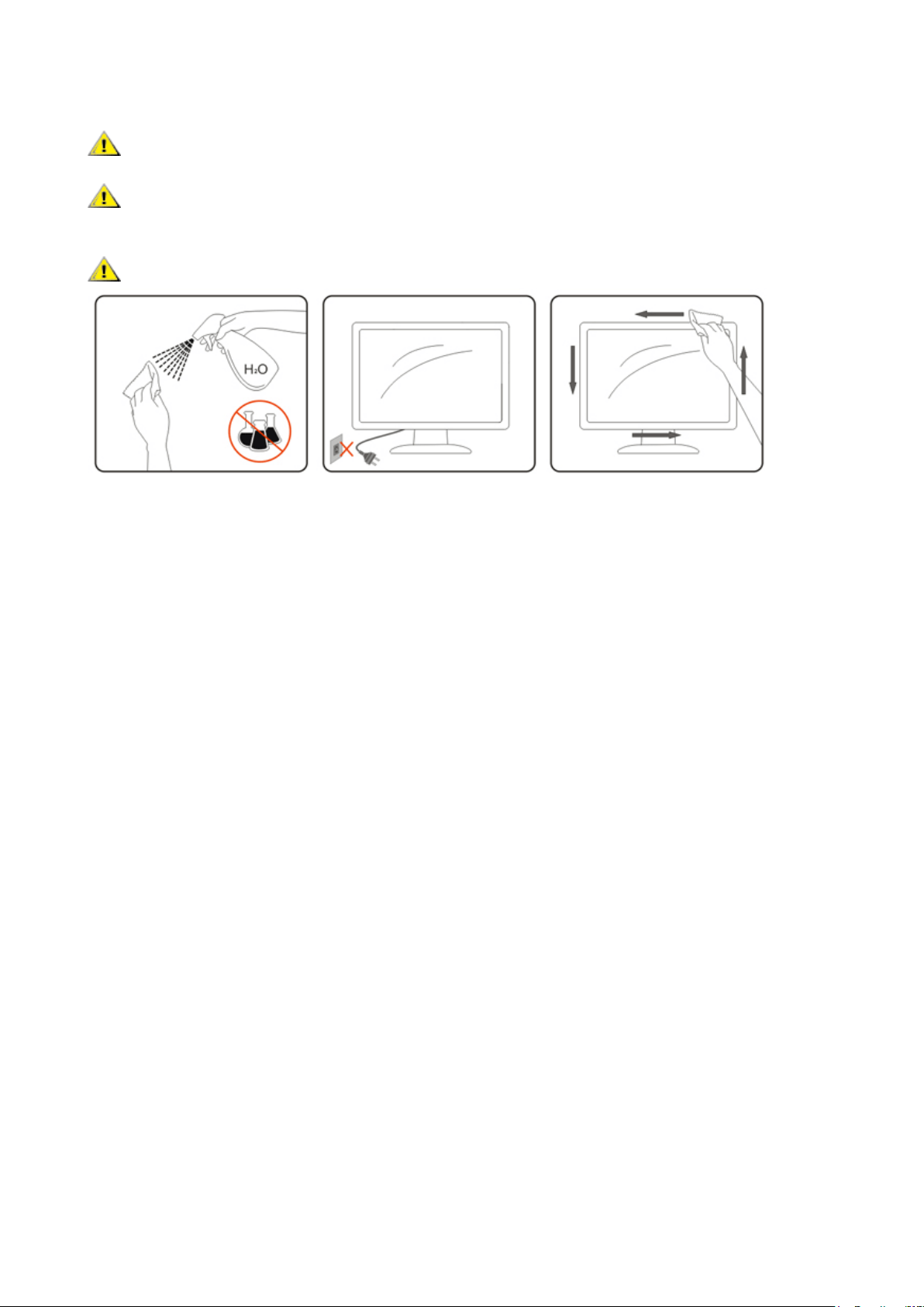
Clean the cabinet regularly with a water-dampened, soft cloth.
When cleaning use a soft cotton or microber cloth. The cloth should be damp and almost dry, do not allow liquid
into the case.
Please disconnect the power cord before cleaning the product.

5
Other
If the product is emitting a strange smell, sound or smoke, disconnect the power plug IMMEDIATELY and contact a
Service Center.
Make sure that the ventilating openings are not blocked by a table or curtain.
Do not engage the LCD monitor in severe vibration or high impact conditions during operation.
Do not knock or drop the monitor during operation or transportation.
The power cords shall be safety approved. For Germany, it shall be H03VV-F, 3G, 0.75 mm2, or better. For other
countries, the suitable types shall be used accordingly.
Excessive sound pressure from earphones and headphones can cause hearing loss. Adjustment of the equalizer to
maximum increases the earphones and headphones output voltage and therefore the sound pressure level.
6
Setup
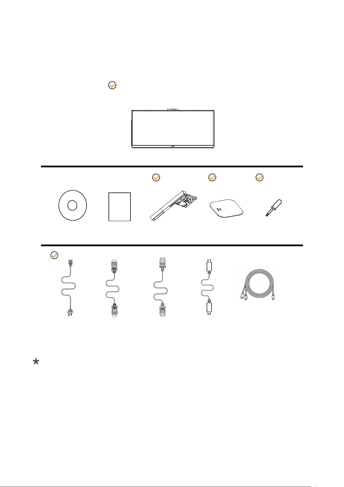
Contents in Box
*
*
HDMI
Cable
USB C-C Cable
DP
Cable
*
CD Manual Warranty Card Stand Base Screwdriver
Monitor
Power Cable
USB C-C/A
Cable
*
*
*
Not all signal cables will be provided for all countries and regions. Please check with the local dealer or AOC branch
oce for conrmation.
7
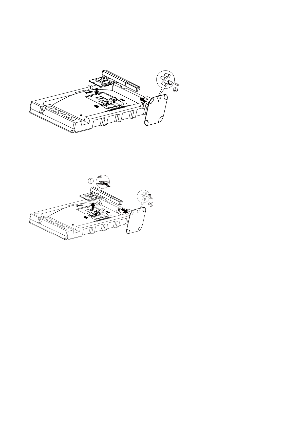
Setup Stand & Base
Please setup or remove the base following the steps as below.
Setup:
Remove:
8
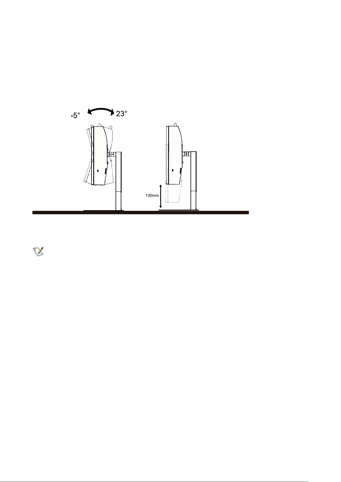
Adjusting Viewing Angle
For optimal viewing it is recommended to look at the full face of the monitor, then adjust the monitor’s angle to your own
preference.
Hold the stand so you will not topple the monitor when you change the monitor’s angle.
You are able to adjust the monitor as below:
NOTE:
Do not touch the LCD screen when you change the angle. Touching the LCD screen may cause damage.
Warning
:
1. To avoid potential screen damage, such as panel peeling, ensure that the monitor does not tilt downward by more than
-5 degrees.
2. Do not press the screen while adjusting the angle of the monitor. Grasp only the bezel.
9
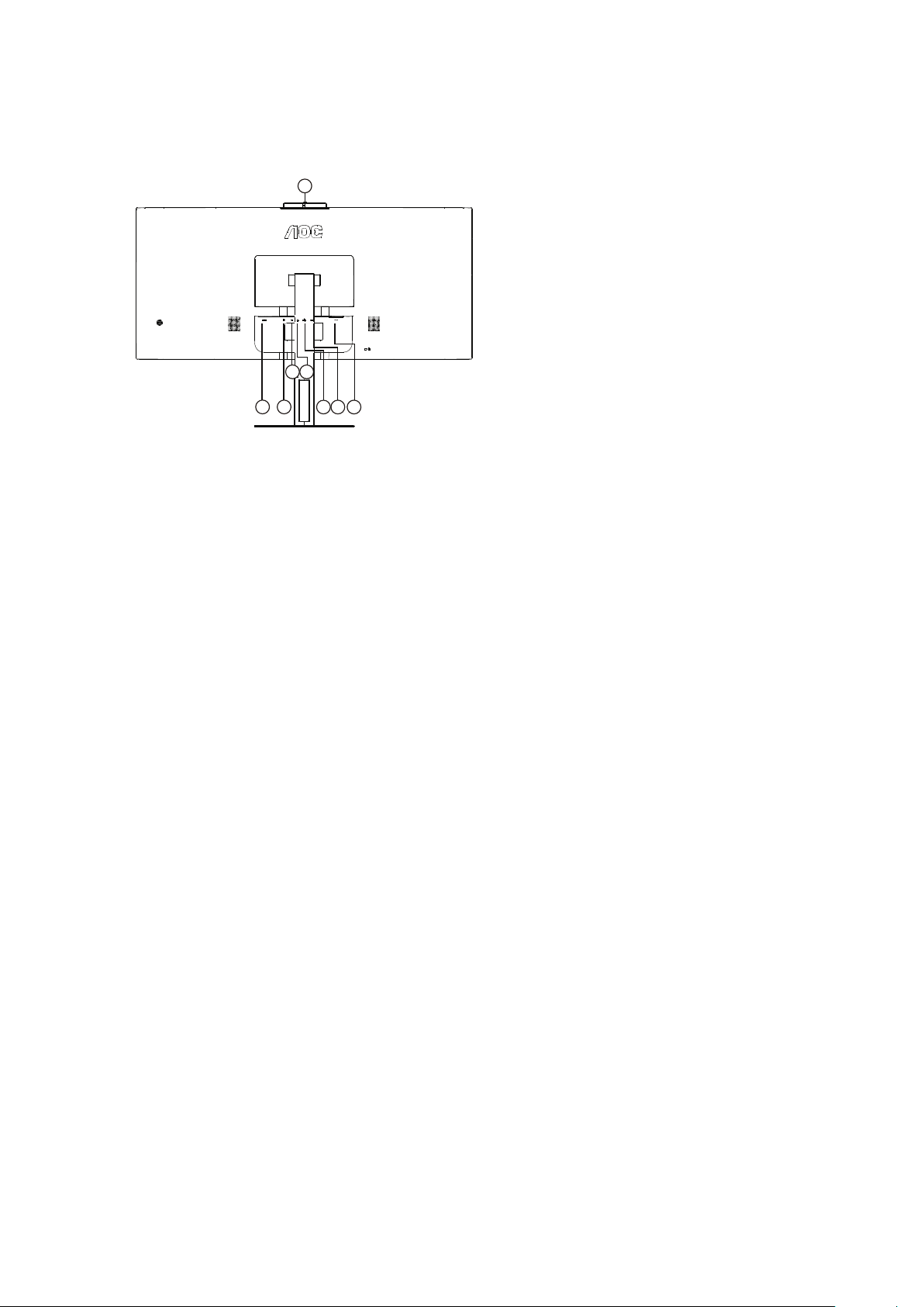
Connecting the Monitor
Cable Connections In Back of Monitor and Computer:
21
4
6 7
3
5
X
8
1. HDMI
2. DP
3. USB C
4. Earphone
5. USB3.2 Gen1+chargingx1
USB3.2 Gen1x1
6. USB3.2 Gen1x2
7. Power
8. Camera
Connect to PC
1. Connect the power cord to the back of the display rmly.
2. Turn o your computer and unplug its power cable.
3. Connect the display signal cable to the video connector on the back of your computer.
4. Plug the power cord of your computer and your display into a nearby outlet.
5. Turn on your computer and display.
If your monitor displays an image, installation is complete. If it does not display an image, please refer Troubleshooting.
To protect equipment, always turn o the PC and LCD monitor before connecting.
10
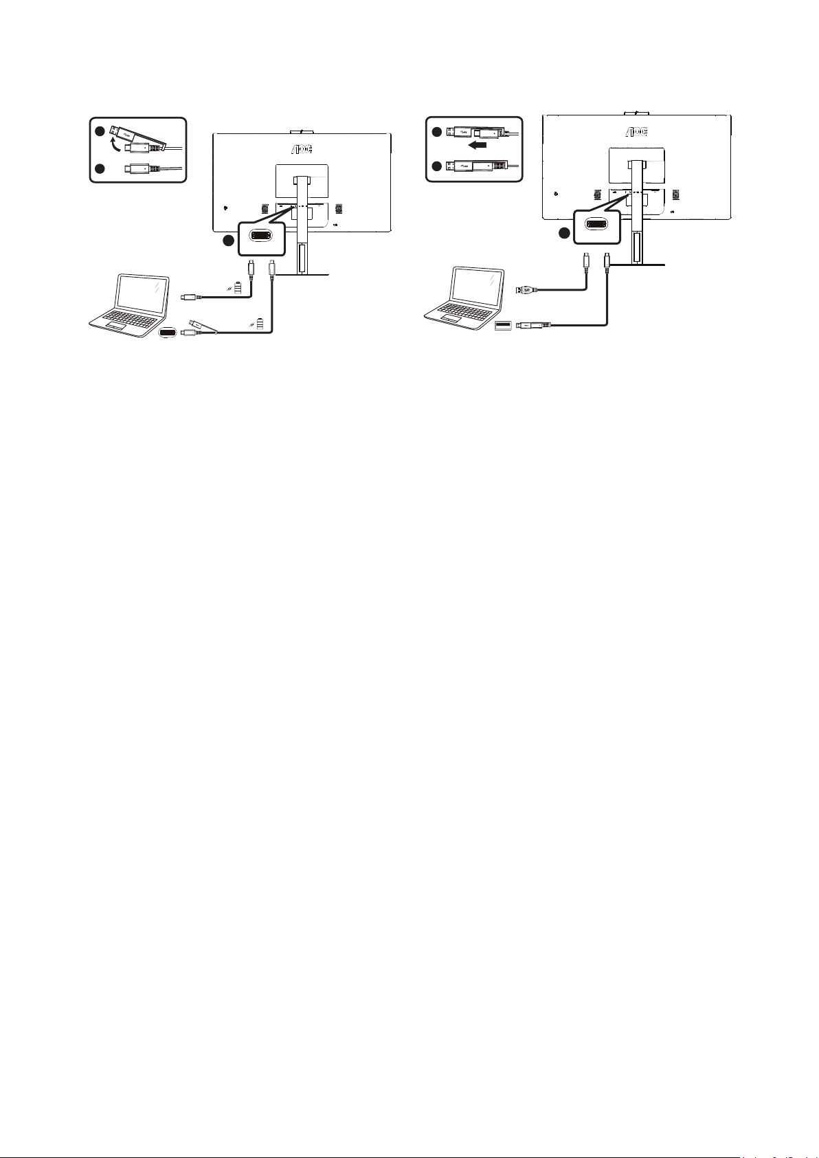
Connect the USB C-C/A Cable
X
X
USB C-C USB C-A
OR
USB C
USB Type-C
OR
USB C
USB Type-A
a-1
a-2
a-1
a-2
a
a
11
Hello webcam
The webcam is equipped with advanced sensors for Windows Hello facial recognition, which conveniently logs you into
your Windows devices in less than 2 seconds, 3 times faster than a password. How to enable Windows Hello™ webcam?
Monitor with Windows Hello webcam can be enabled by simply connecting your USB cable from your PC to the “USB
C” port of this monitor. Now, the webcam with Windows Hello is ready to work as long as the Windows Hello setting in
Windows10 is complete. Refer to Windows ocial website for the settings: https://support.microsoft.com/help/4028017/
windows-learn-about-windows-hello-and-set-it-up.
Please note that Windows 10 system is required for setting up Windows Hello: facial recognition; with an edition lower
than Windows 10 or Mac OS, the webcam can work without the function of facial recognition. With Windows 7 the driver
is required to activate this webcam.
Please follow the steps for the setting:
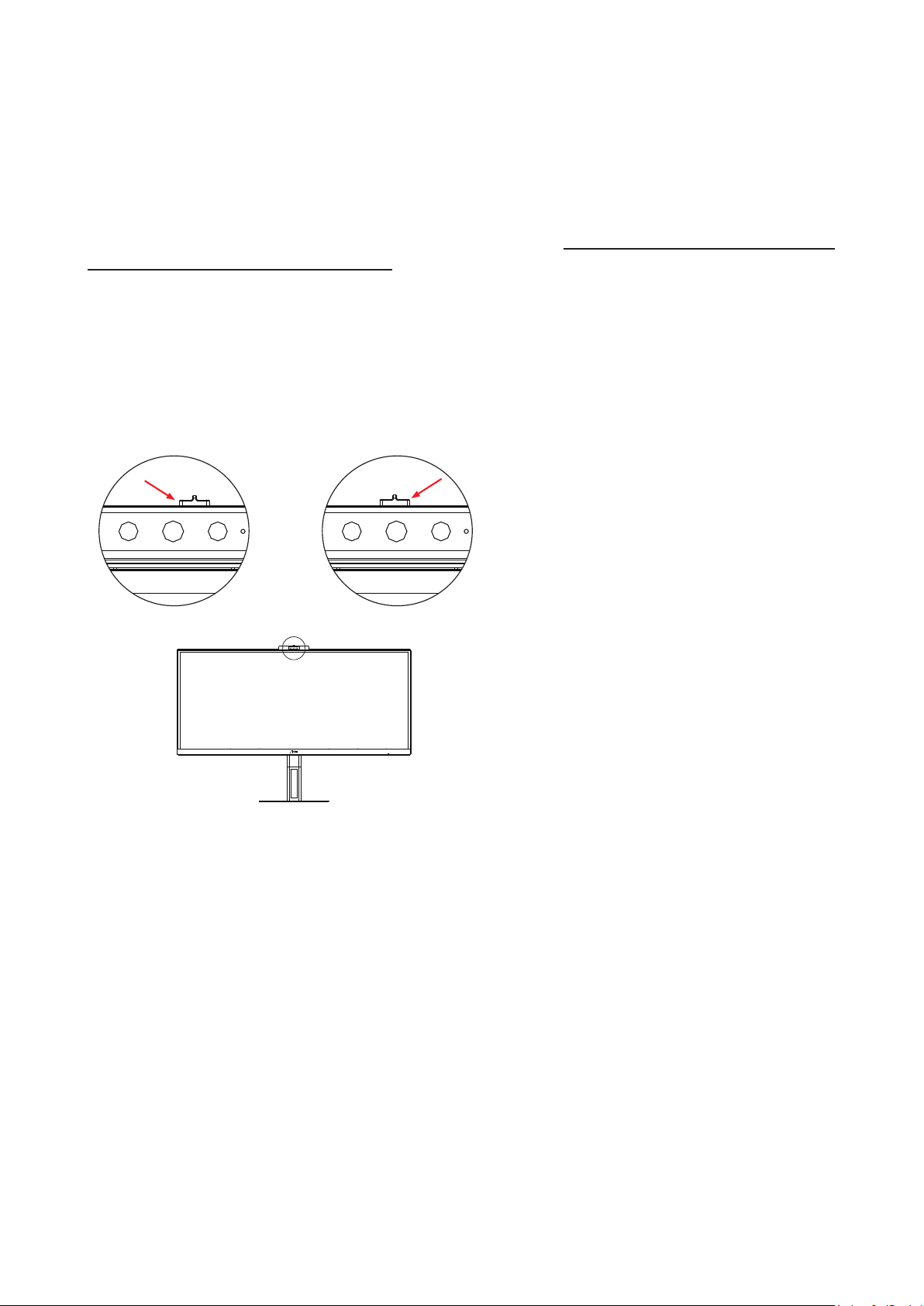
Slide the camera shutter open or close to enable/disable the camera.
a. Slide to open. b. Slide to close.
Noted: Shutter only blocks the lens, to close the mic you need to close the VC software.
12
Wall Mounting
Preparing to Install An Optional Wall Mounting Arm(Screw diameter is M4 and length is 10mm).
4
5
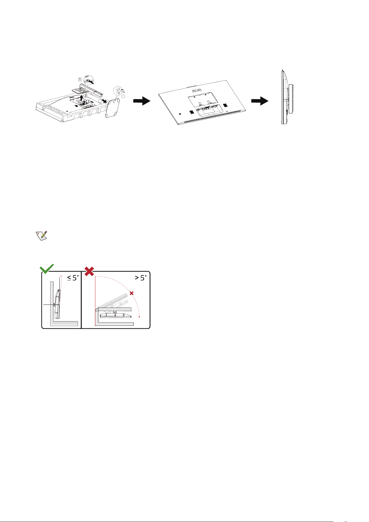
This monitor can be attached to a wall mounting arm you purchase separately. Disconnect power before this procedure.
Follow these steps:
1. Remove the base.
2. Follow the manufacturer’s instructions to assemble the wall mounting arm.
3. Place the wall mounting arm onto the back of the monitor. Line up the holes of the arm with the holes in the back of
the monitor.
4. Reconnect the cables. Refer to the user’s manual that came with the optional wall mounting arm for instructions on
attaching it to the wall.
Noted: VESA mounting screw holes are not available for all models, please check with the dealer or ocial
department of AOC.
-5°
0° 90°
* Display design may dier from those illustrated.
Warning
:
1. To avoid potential screen damage, such as panel peeling, ensure that the monitor does not tilt downward by more than
-5 degrees.
2. Do not press the screen while adjusting the angle of the monitor. Grasp only the bezel.

13
AMD FreeSync function (Available for selective models)
1. AMD FreeSync function is working with DP/HDMI/USB C
2. Compatible Graphics Card: Recommend list is as the below, also could be checked by visiting www.AMD.com
Graphics Cards
• Radeon™ RX Vega series
• Radeon™ RX 500 series
• Radeon™ RX 400 series
• Radeon™ R9/R7 300 series
(
R9 370/X, R7 370/X, R7 265
except
)
• Radeon™ Pro Duo (2016)
• Radeon™ R9 Nano series
• Radeon™ R9 Fury series
• Radeon™ R9/R7 200 series (R9 270/X, R9 280/X
except)
Processors
• AMD Ryzen™ 7 2700U
• AMD Ryzen™ 5 2500U
• AMD Ryzen™ 5 2400G
• AMD Ryzen™ 3 2300U
• AMD Ryzen™ 3 2200G
• AMD PRO A12-9800
• AMD PRO A12-9800E
• AMD PRO A10-9700
• AMD PRO A10-9700E
• AMD PRO A8-9600
• AMD PRO A6-9500
• AMD PRO A6-9500E
• AMD PRO A12-8870
• AMD PRO A12-8870E
• AMD PRO A10-8770
• AMD PRO A10-8770E
• AMD PRO A10-8750B
• AMD PRO A8-8650B
• AMD PRO A6-8570
• AMD PRO A6-8570E
• AMD PRO A4-8350B
• AMD A10-7890K
• AMD A10-7870K
• AMD A10-7850K
• AMD A10-7800
• AMD A10-7700K
• AMD A8-7670K
• AMD A8-7650K
• AMD A8-7600
• AMD A6-7400K

14
Adaptive-Sync function (Available for selective models)
1. Adaptive-Sync function is working with DP/HDMI/USB C
2. Compatible Graphics Card: Recommend list is as the below, also could be checked by visiting www.AMD.com
Graphics Cards
• Radeon™ RX Vega series
• Radeon™ RX 500 series
• Radeon™ RX 400 series
• Radeon™ R9/R7 300 series
(
R9 370/X, R7 370/X, R7 265
except
)
• Radeon™ Pro Duo (2016)
• Radeon™ R9 Nano series
• Radeon™ R9 Fury series
• Radeon™ R9/R7 200 series (R9 270/X, R9 280/X
except)
Processors
• AMD Ryzen™ 7 2700U
• AMD Ryzen™ 5 2500U
• AMD Ryzen™ 5 2400G
• AMD Ryzen™ 3 2300U
• AMD Ryzen™ 3 2200G
• AMD PRO A12-9800
• AMD PRO A12-9800E
• AMD PRO A10-9700
• AMD PRO A10-9700E
• AMD PRO A8-9600
• AMD PRO A6-9500
• AMD PRO A6-9500E
• AMD PRO A12-8870
• AMD PRO A12-8870E
• AMD PRO A10-8770
• AMD PRO A10-8770E
• AMD PRO A10-8750B
• AMD PRO A8-8650B
• AMD PRO A6-8570
• AMD PRO A6-8570E
• AMD PRO A4-8350B
• AMD A10-7890K
• AMD A10-7870K
• AMD A10-7850K
• AMD A10-7800
• AMD A10-7700K
• AMD A8-7670K
• AMD A8-7650K
• AMD A8-7600
• AMD A6-7400K
15
Adjusting
Hotkeys
X
4
1
3
5
2
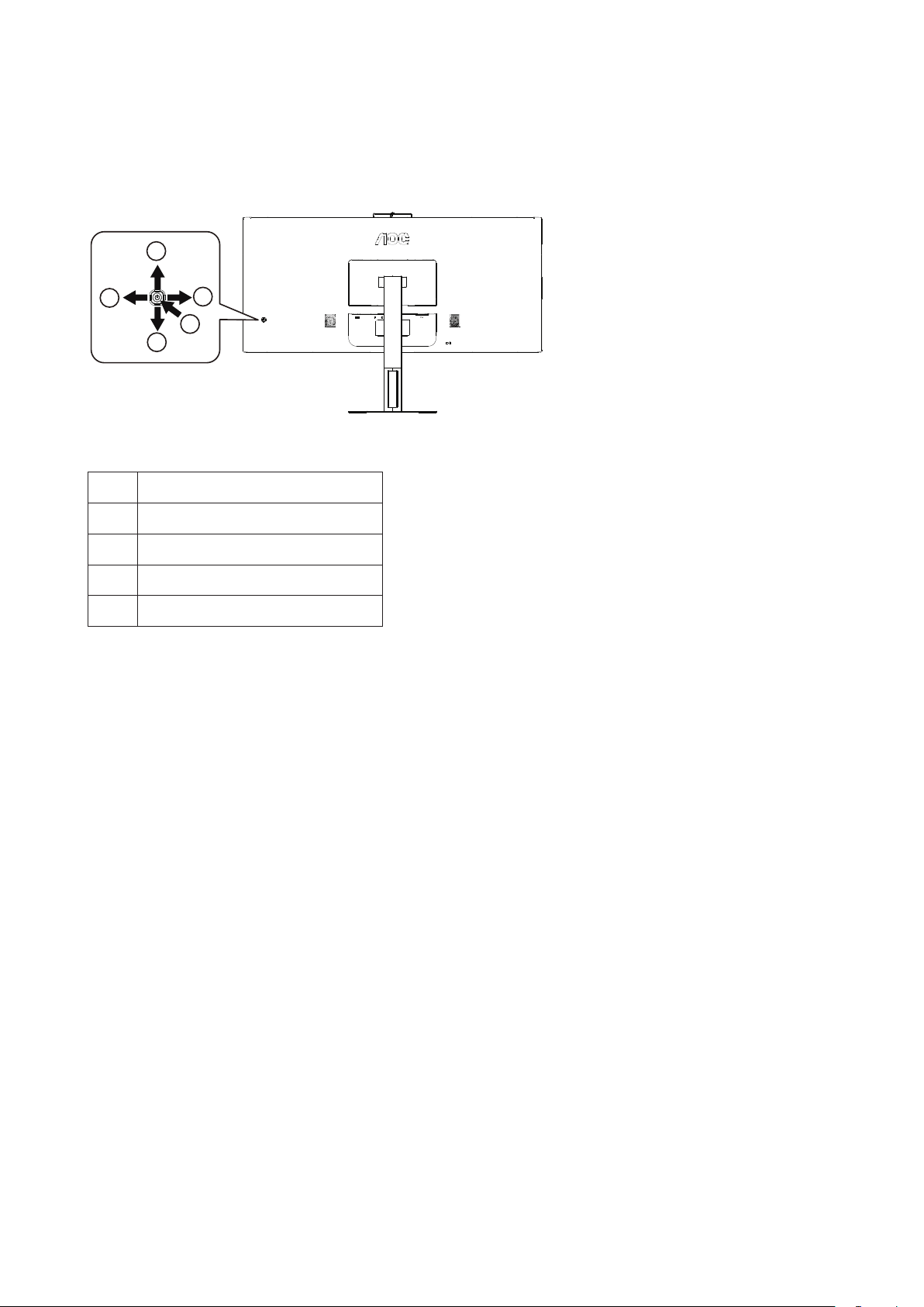
1 Source/Exit/Up
2 MIC/down
3 Clear Vision/Left
4 Volume/Right
5 Power/ Menu/Enter
Menu/Enter
When there is no OSD, Press to display the OSD or conrm the selection. Press about 2 second to turn o the monitor.
Power
Press the Power button to turn on the monitor.
Volume/Right
When there is no OSD, Press Volume button to active volume adjustment bar, Press Left or Right to adjust volume.
Source/Exit
When the OSD is closed, press Source/Exit button will be Source hot key function.
MIC/down
When there is no OSD, press this button to enter MIC adjustment. Then press Left or Right button to choose o or on.
16
Clear Vision
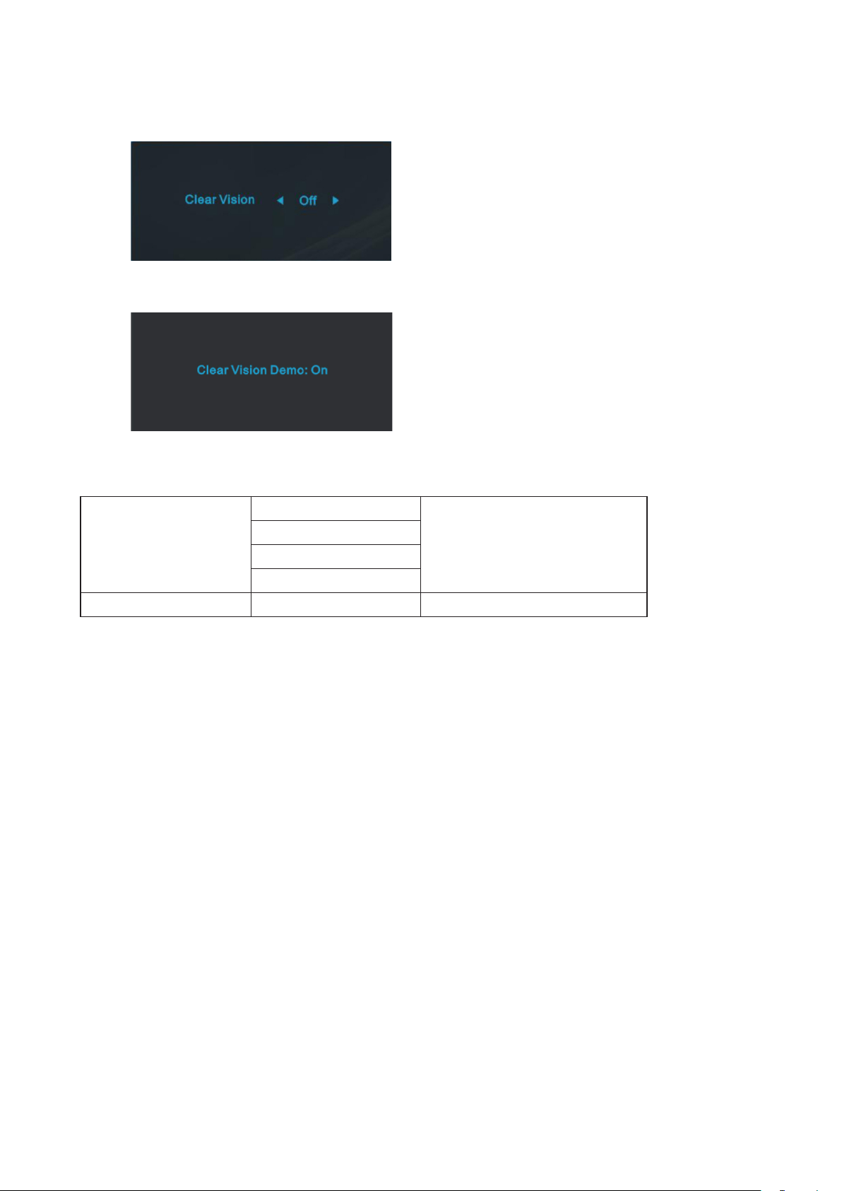
1. When there is no OSD, Press the “Left” button to activate Clear Vision.
2. Use the “Left” or “Right” buttons to select between weak, medium, strong, or o settings. Default setting is always “o”.
3. Press and hold “Left” button for 5 seconds to activate the Clear Vision Demo, and a message of “Clear Vision Demo:
on” will be display on the screen for a duration of 5 seconds. Press and hold “Left” button for 5 seconds again, Clear
Vision Demo will be o.
Clear Vision function provides the best image viewing experience by converting low resolution and blurry images into
clear and vivid images.
Clear Vision
O
Adjust the Clear Vision
Weak
Medium
Strong
Clear Vision Demo On or O Disable or Enable Demo

17
OSD Setting
Basic and simple instruction on the control keys.
Luminance Color Setup Picture Boost OSD Setup ExitExtra
Contrast 50
Brightness 70
Eco mode Standard
Gamma Gamma 1
DCR Off
HDR Mode Off
Game Setting
PIP Setting
PIP
1). Press the
MENU-button
to activate the OSD window.
2). Press
Left
or
Right
to navigate through the functions. Once the desired function is highlighted, press the
MENU-
button
to activate it, press
Left
or
Right
to navigate through the sub-menu functions. Once the desired function is
highlighted, press
MENU-button
to activate it.
3). Press
Left
or
Right
to change the settings of the selected function. Press
Exit–button
to exit. If you want to adjust
any other function, repeat steps 2-3.
4). OSD Lock/Unlock Function: To lock or unlock the OSD, press and hold the
Down–button
for 10s while OSD function
is not active.
Notes:
1). If the product has only one signal input, the item of “Input Select” is disable to adjust.
2). ECO modes (except Standard mode), Clear vision, DCR, DCB mode and Picture Boost, for these states that only one
state can exist.
18
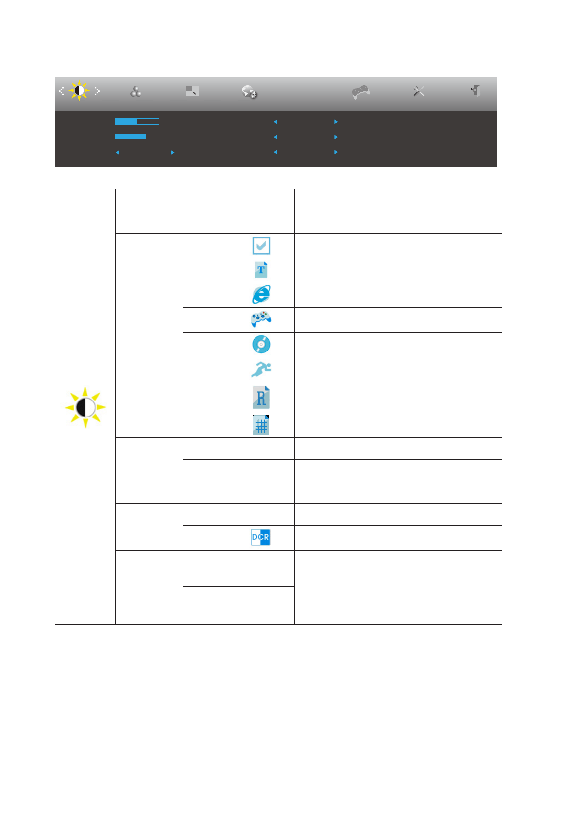
Luminance
Luminance Color Setup Picture Boost OSD Setup ExitExtra
Contrast 50
Brightness 70
Eco mode Standard
Gamma Gamma 1
DCR Off
HDR Mode Off
Game Setting
PIP Setting
PIP
Contrast 0-100 Contrast from Digital-register.
Brightness 0-100 Backlight Adjustment
Eco mode
Standard Standard Mode
Text Text Mode
Internet Internet Mode
Game Game Mode
Movie Movie Mode
Sports Sports Mode
Reading Reading Mode
Uniformity Uniformity Mode
Gamma
Gamma1 Adjust to Gamma 1
Gamma2 Adjust to Gamma 2
Gamma3 Adjust to Gamma 3
DCR
O Disable dynamic contrast ratio
On Enable dynamic contrast ratio
HDR Mode
O
Optimized for the color and contrast of the picture,
which will simulate showing the HDR eect.
HDR Picture
HDR Movie
HDR Game
Note:
When “HDR Mode” is set to “non-o”, the items “Contrast”, “Eco mode”, “Gamma” cannot be adjusted.
19
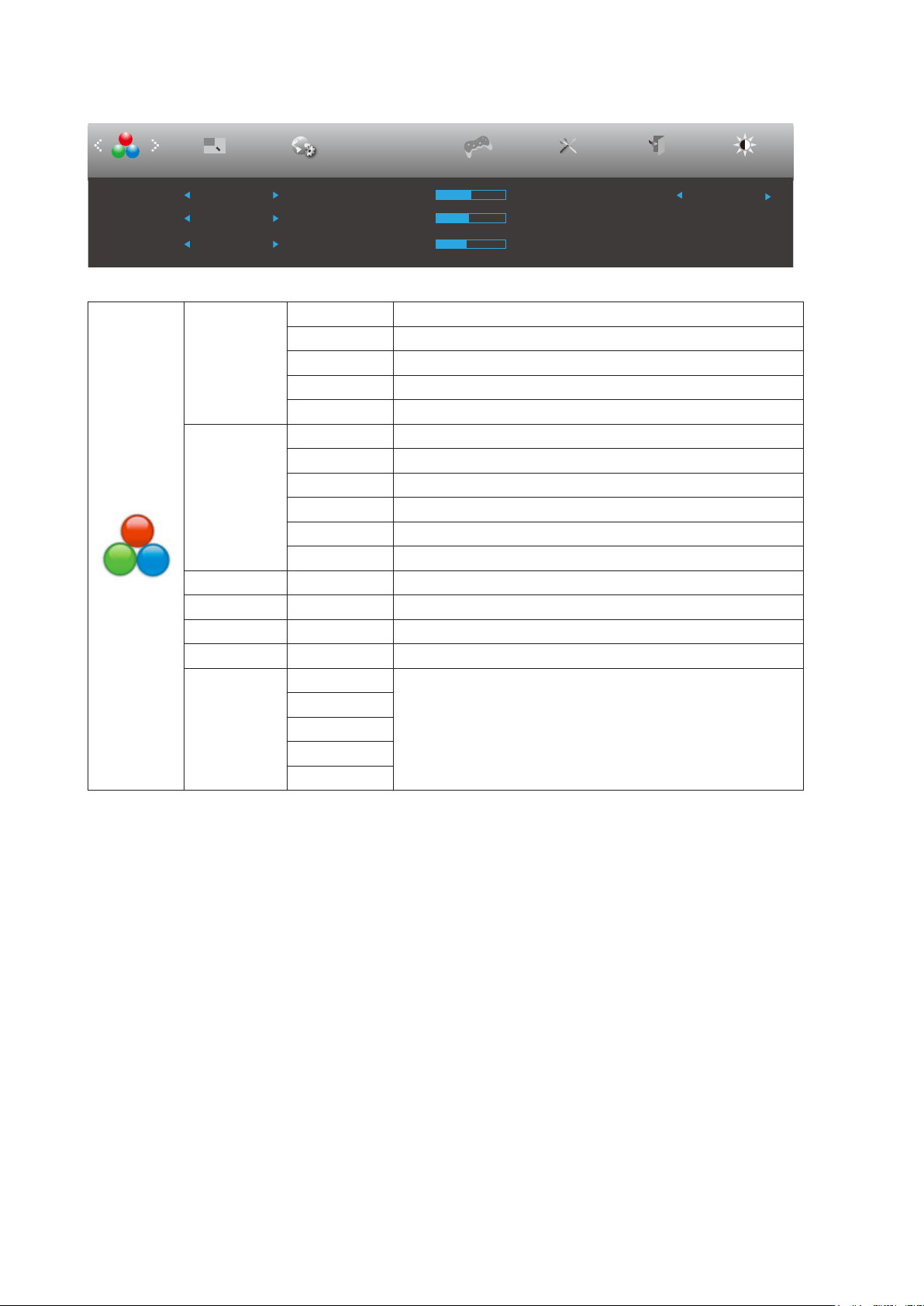
Color Setup
Picture Boost OSD Setup ExitExtra
Luminance
Red 50
Green 50
Blue 50DCB Demo Off
Color Temp. Warm
DCB Mode Off
Color Setup
Game Setting
PIP Setting
PIP
LowBlue Mode
Off
Color Temp.
Warm Recall Warm Color Temperature from EEPROM.
Normal Recall Normal Color Temperature from EEPROM.
Cool Recall Cool Color Temperature from EEPROM.
sRGB Recall SRGB Color Temperature from EEPROM.
User Recall User Color Temperature from EEPROM.
DCB Mode
Full Enhance Disable or Enable Full Enhance Mode
Nature Skin Disable or Enable Nature Skin Mode
Green Field Disable or Enable Green Field Mode
Sky-blue Disable or Enable Sky-blue Mode
Auto Detect Disable or Enable AutoDetect Mode
O Disable or Enable DCB Mode
DCB Demo on or o Disable or Enable Demo
Red 0-100 Red gain from Digital-register.
Green 0-100 Green gain from Digital-register.
Blue 0-100 Blue gain from Digital-register.
LowBlue
Mode
O
Decrease blue light wave by controlling color temperature
Reading
Oce
Internet
Multimedia
Note:
When “HDR Mode” under “Luminance” is set to “non-o”, all items under “Color Setup” cannot be adjusted.

20
Picture Boost
OSD Setup ExitExtra
Luminance
Brightness 50
Contrast 50
H. Position 0
V. Position 0
Bright Frame off
Frame Size 14
Picture Boost
Color Setup
Game Setting
PIP Setting
PIP
Bright Frame On or O Disable or Enable Bright Frame
Frame Size 14-100 Adjust Frame Size
Brightness 0-100 Adjust Frame Brightness
Contrast 0-100 Adjust Frame Contrast
H. position 0-100 Adjust Frame horizontal Position
V. position 0-100 Adjust Frame vertical Position
Note:
When “HDR Mode” under “Luminance” is set to “non-o”, all items under “Picture Boost” cannot be adjusted.
21
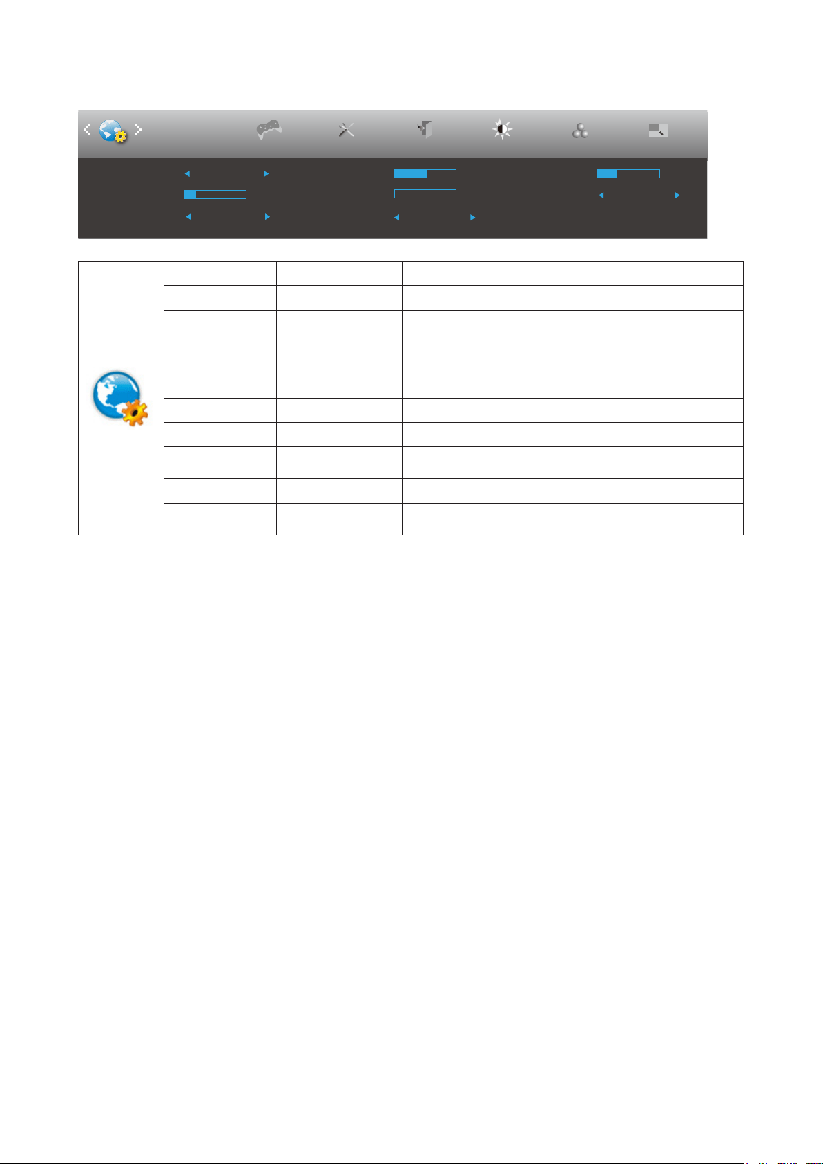
OSD Setup
ExitExtra
Luminance
Color Setup
H. Position 50
V. Position 0
Transparence 25
Language English
Timeout 10
DP Capability 1.2 USB
Break Reminder Off
OSD Setup
Picture Boost
Game Setting
Off
PIP Setting
PIP
Language Select the OSD language
Timeout 5-120 Adjust the OSD Timeout
DP Capability 1.1/1.2
Select a compatible DP version.
Please note that:
1. The Adaptive-Sync/AMD FreeSync function is only
available with DP1.2.
2. If the DP video content supports DP1.2, set the DP
version to DP1.2; otherwise, select DP1.1.
H. Position 0-100 Adjust the horizontal position of OSD
V. Position 0-100 Adjust the vertical position of OSD
USB*
High-Speed/High-
res/O
Turn o USB function or set USB interface version.
Transparence 0-100 Adjust the transparence of OSD
Break Reminder On or O
Break reminder if the user continuously work for more than
1hrs
Note:
*: USB C(DP Alt) signal input, and “USB” is set to “High-res”, the maximum resolution is 3440x1440@100Hz.
22
PIP Setting
Picture Boost OSD Setup
PIP Setting
ExitExtra
PIP
Luminance
Size
Position
AudioSub Source DP
PIP Setting Off Small Swap Off
Main Source
HDMI1
Off
Right-up
Color Setup
Game Setting
PIP
PIP Setting Off / PIP / PBP Disable or Enable PIP or PBP.
Main Source* Select main screen source.
Sub Source* Select sub screen source.
Size Small / Middle / Large Select screen size.
Position
Right-Up
Set the screen location.
Right-Down
Left-Up
Left-Down
Audio
On: PIP Audio
Disable or Enable Audio Setup.
Off: Main Audio
Swap
On: Swap
Swap the screen source.
Off: non action
Refer to the table below for main/sub input source compability
:
Sub Main HDMI DP USB-C
HDMI V V V
DP V V V
USB-C V V V
*PxP color-related adjustments can only be operated by main, and sub is not supported.
So Main & sub will have dierent colors.
23
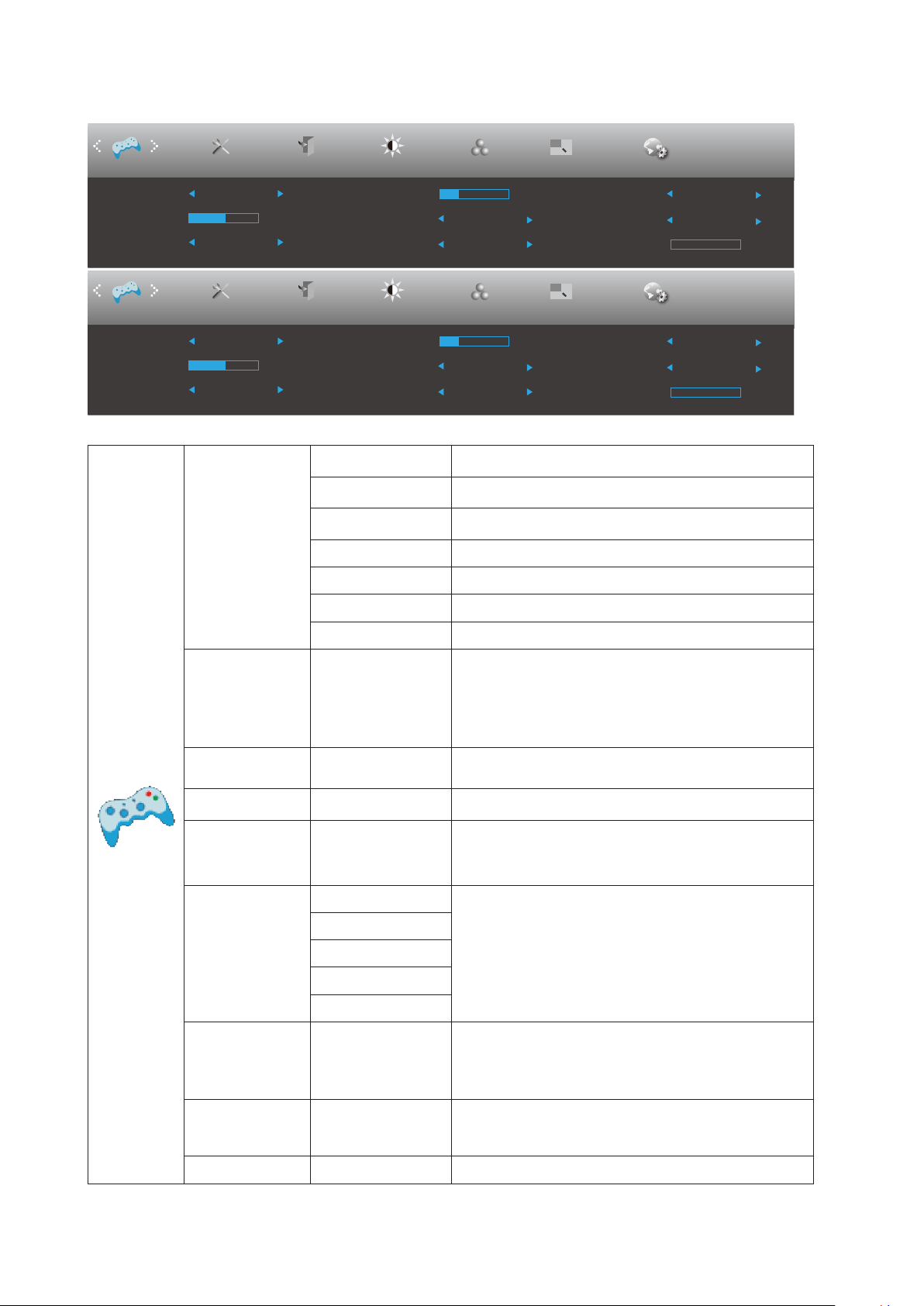
Game Setting
Low Input Lag
Overdrive
Shadow Control
Game Mode Off
Off
Off
Off
50
Game Color
10
Adaptive-Sync
Off
Frame Counter
Off
Dial Point
MBR
0
Low Input Lag
Overdrive
Shadow Control
Game Mode Off
Off
Off
Off
50
Game Color
10
AMD FreeSync
Off
Frame Counter
Off
Dial Point
MBR
0
ExitExtra
Luminance
Color Setup
Picture Boost
OSD Setup
PIP Setting
PIP
Game Setting
ExitExtra
Luminance
Color Setup
Picture Boost
OSD Setup
PIP Setting
PIP
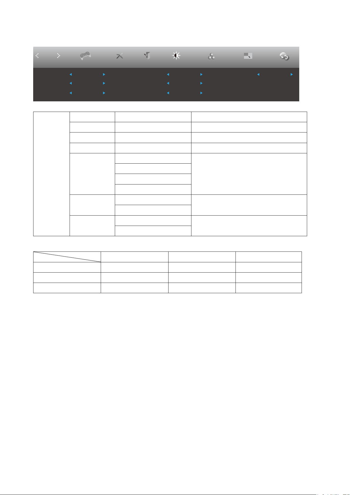
Game Setting
Game Mode
FPS
For playing FPS (First Person Shooters) games.
Improves dark theme black level details.
RTS
For playing RTS (Real Time Strategy). Improves the
image quality.
Racing
For playing Racing games, Provides fastest response
time and high color saturation.
Gamer 1 User’s preference settings saved as Gamer 1.
Gamer 2 User’s preference settings saved as Gamer 2.
Gamer 3 User’s preference settings saved as Gamer 3.
O No optimization by Smart image game
Shadow Control 0-100
Shadow Control Default is 50, then end-user can adjust
from 50 to 100 or 0 to increase contrast for clear picture.
1. If picture is too dark to be saw the detail clearly,
adjusting from 50 to100 for clear picture.
2. If picture is too white to be saw the detail clearly,
adjusting from 50 to0 for clear picture
Low Input Lag On/O Turn o frame buer to decrease input lag
Game Color 0-20
Game Color will provide 0-20 level for adjusting
saturation to get better picture.
Dial Point On/O
The“Dial Point”function places an aiming indicator in the
center of screen for helping gamers to play First Person
Shooter (FPS) games with an accurate and precise
aiming.
Overdrive
Weak
Adjust the response time.
Note:
If the user adjusts OverDrive to “High,” the displayed
image may be blurred. Users can adjust the OverDrive
level or turn it o according to their preferences.
Medium
Strong
Boost
O
Adaptive-Sync/
AMD FreeSync
(Available for
selective models)
On/O Adjust the Adaptive-Sync/AMD FreeSync.
Frame Counter
O / Right-Up /
Right-Down / Left-
Down / Left-Up
Display V frequency on the corner selected
MBR 0 ~ 20 Adjust the Motion Blur Reduction.

24
Note:
When “HDR Mode” under “Luminance” is set to “non-o”, the items “Game Mode”, “Shadow Control”, “Game Color” cannot
be adjusted.
25
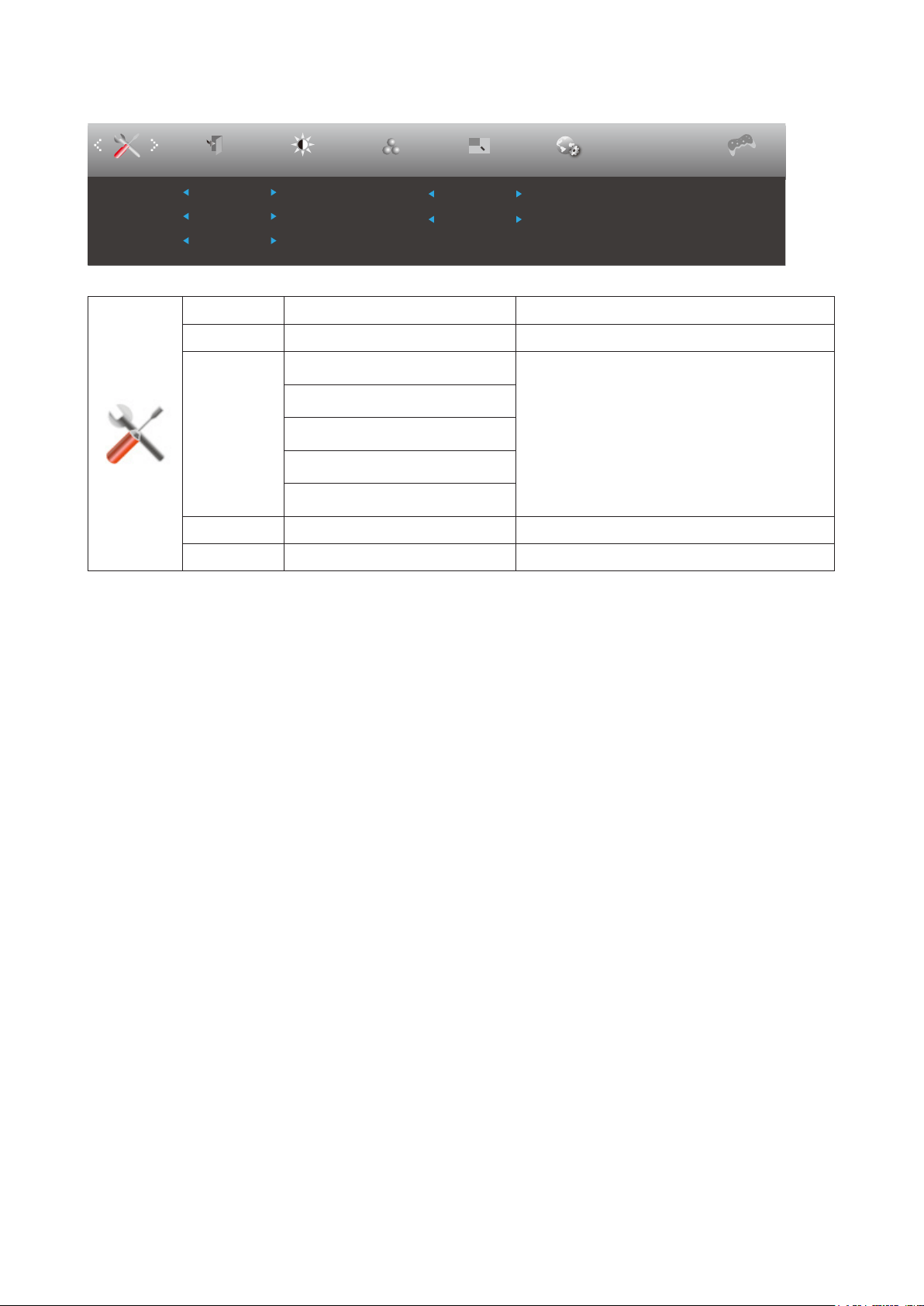
Extra
Picture Boost OSD SetupExit
Luminance
Color Setup
Off Timer 00
Input Select Auto
Reset No
Image Ratio Wide
DDC/CI Yes
Resolution : 3440(H)X1440(V)
H. Frequency : 150KHz
V. Frequency : 100Hz
Extra
Game Setting
PIP Setting
PIP
Input Select Auto/ HDMI/ DP/ USB C* Select Input Signal Source
O timer 0-24 (hrs) Select DC o time
Image Ratio
Wide
Select image ratio for display.
4:3
1:1
Movie 1
Movie 2
DDC/CI Yes or No Turn ON/OFF DDC/CI Support
Reset Yes or No Reset the menu to default.
Note:
*: The device must support USB C (DP Alt).
The USB C (DP Alt) function is o by default when used for the rst time or after resetting the OSD menu, and can be
reenabled
in one of the following ways:
1) The monitor is turned on. and o a total of 3 times.
2) The “USB” option in the “Others” section of the OSD menu is set to not closed.

26
Exit
Picture Boost OSD Setup
Luminance
Color Setup
Exit
Extra
Game Setting
PIP Setting
PIP
Exit Exit the main OSD

27
LED Indicator
Status LED Color
Full Power Mode White
Active-o Mode Orange
28
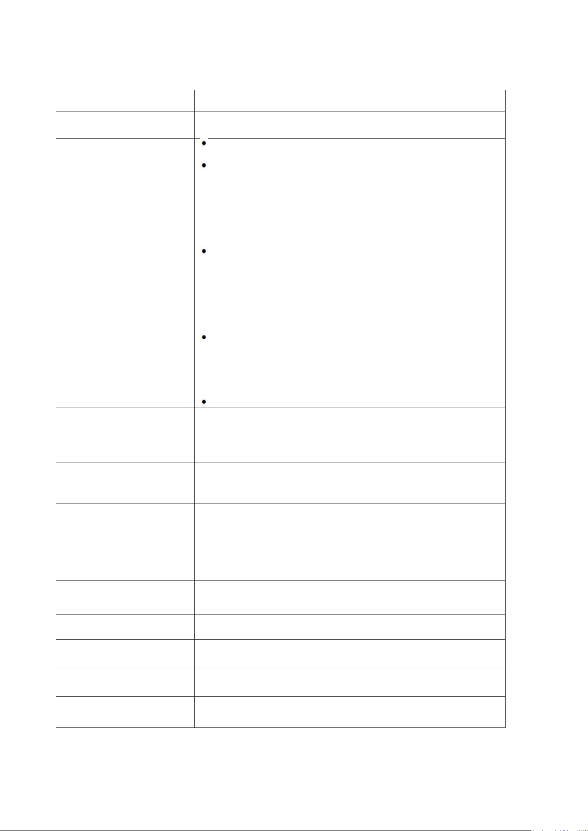
Troubleshoot
Problem & Question
Possible Solutions
Power LED Is Not ON
Make sure the power button is ON and the Power Cord is properly connected
to a grounded power outlet and to the monitor.
No images on the screen
Is the power cord connected properly?
Check the power cord connection and power supply.
Is the video cable connected correctly?
(Connected using the VGA cable)
Check the VGA cable connection.
(Connected using the HDMI cable)
Check the HDMI cable connection.
(Connected using the DP cable)
Check the DP cable connection.
* VGA/HDMI/DP input is not available on every model.
If the power is on, reboot the computer to see the initial screen (the login
screen.)
If the initial screen (the login screen) appears, boot the computer in the
applicable mode (the safe mode for Windows 7/8/10) and then change the
frequency of the video card.
(Refer to the Setting the Optimal Resolution)
If the initial screen (the login screen) does not appear, contact the Service
Center or your dealer.
Can you see “Input Not Supported” on the screen?
You can see this message when the signal from the video card exceeds
the maximum resolution and frequency that the monitor can handle
properly.
Adjust the maximum resolution and frequency that the monitor can handle
properly.
Make sure the AOC Monitor Drivers are installed.
Picture Is Fuzzy & Has
Ghosting Shadowing Problem
Adjust the Contrast and Brightness Controls.
Press hot-key (AUTO) to auto-adjust.
Make sure you are not using an extension cable or switch box. We
recommend plugging the monitor directly to the video card output connector
on the back.
Picture Bounces, Flickers Or
Wave Pattern Appears In The
Picture
Move electrical devices that may cause electrical interference as far away
from the monitor as possible.
Use the maximum refresh rate your monitor is capable of at the resolution
you are using.
Monitor Is Stuck In Active O-
Mode”
The Computer Power Switch should be in the ON position.
The Computer Video Card should be snugly tted in its slot.
Make sure the monitor’s video cable is properly connected to the computer.
Inspect the monitor’s video cable and make sure no pin is bent.
Make sure your computer is operational by hitting the CAPS LOCK key on
the keyboard while observing the CAPS LOCK LED. The LED should either
turn ON or OFF after hitting the CAPS LOCK key.
Missing one of the primary
colors (RED, GREEN, or
BLUE)
Inspect the monitor’s video cable and make sure that no pin is damaged.
Make sure the monitor’s video cable is properly connected to the computer.
Screen image is not centered
or sized properly
Adjust H-Position and V-Position or press hot-key (AUTO).
Picture has color defects
(white does not look white)
Adjust RGB color or select desired color temperature.
Horizontal or vertical
disturbances on the screen
Use Windows 7/8/10 shut-down mode to adjust CLOCK and FOCUS.
Press hot-key (AUTO) to auto-adjust.
Regulation & Service
Please refer to Regulation & Service Information which is in the CD manual
or www.aoc.com (to nd the model you purchase in your country and to nd
Regulation & Service Information in Support page.
29
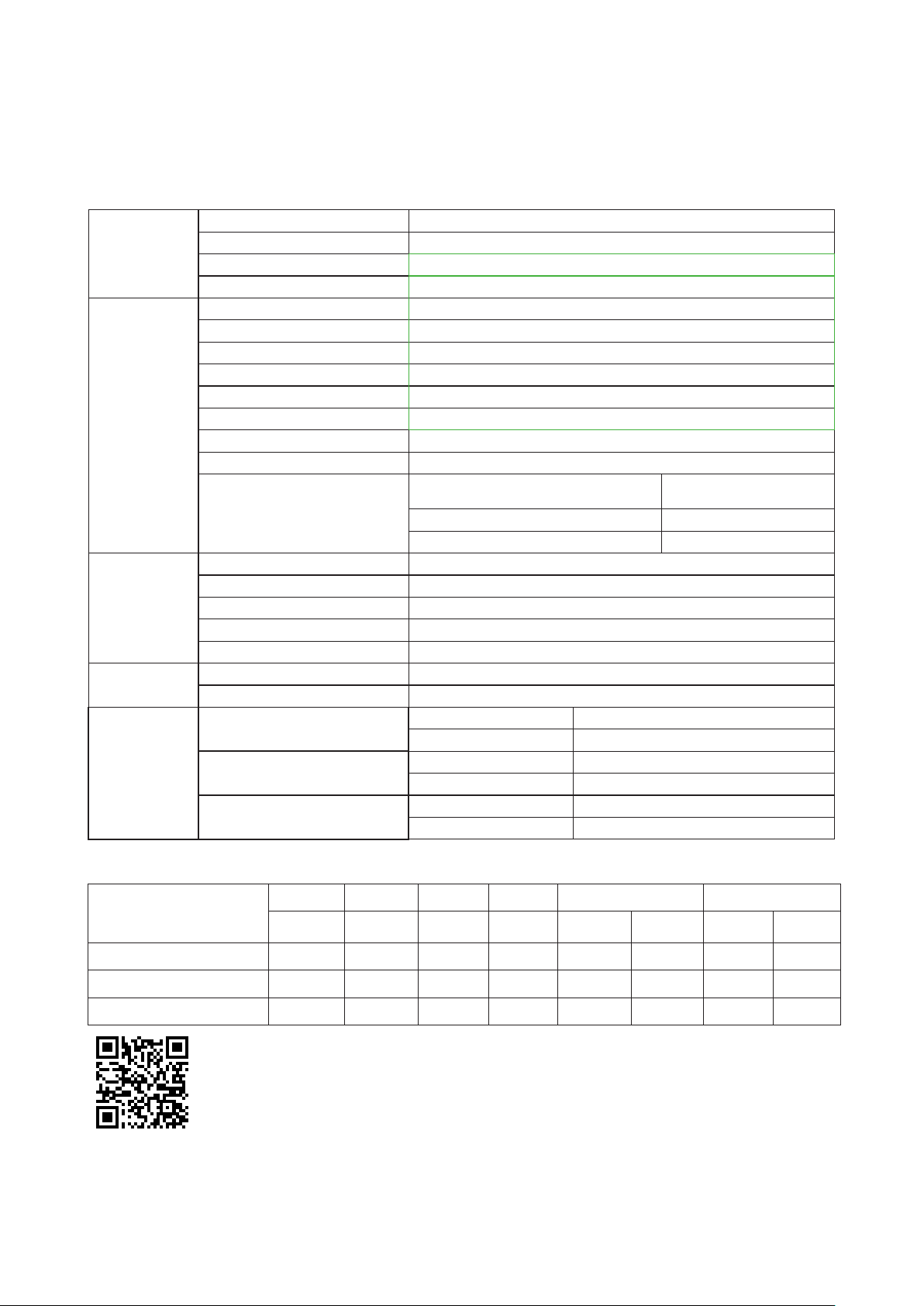
Specification
General Specification
Panel
Model Name CU34V5CW/BK
Driving System TFT Color LCD
Viewable Image Size 86.4 cm Diagonal
Pixel Pitch
0.23175mm(H) x 0.23175mm(V)
Others
Horizontal Scan Range 30k-160kHz
Horizontal Scan Size(Maximum) 797.22mm
Vertical Scan Range 48-100Hz
Vertical Scan Size(Maximum) 333.72mm
Optimal Preset Resolution
3440x1440@60Hz
Max Resolution 3440x1440@100Hz (HDMI/DP/USB C*)
Plug & Play VESA DDC2B/CI
Power Source 100-240V~, 50/60Hz, 3A
Power Consumption
Typical(Default Brightness And
Contrast)
60W
Max. (Brightness = 100, Contrast =100)
≤
190W
Power Saving
≤
0.5W
USB C
USB-C Double-sided Connectable Plug
Ultra-highSpeed Data And Video Transmission
DP Built-in DP Alt Mode
Power Supply USB PD Version 3.0
Maximum Power Supply Up to 65W (5V/3A, 9V/3A, 10V/3A, 12V/3A, 15V/3A, 20V/3.25A)
Physical
Characteristics
Connector Type HDMI/DP/USB C/USB×4/Earphone
Signal Cable Type
Detachable
Environmental
Temperature
Operating 0°~ 40°
Non-Operating -25°~ 55°
Humidity
Operating 10% ~ 85% (Non-Condensing)
Non-Operating 5% ~ 93% (Non-Condensing)
Altitude
Operating 0~ 5000 m (0~ 16404ft )
Non-Operating 0~ 12192m (0~ 40000ft )
*Note: USB C(DP Alt) signal input, and “USB” is set to “High-res”, the maximum resolution is 3440x1440@100Hz
Color bits Limitation:
CU34V5CW/BK
422/420 444/RGB 422/420 444/RGB 422/420 444/RGB
(HDMI2.0) (HDMI2.0) (DP1.2) (DP1.2)
USBC@
USB3.2
USBC@
USB2.0
USBC@
USB3.2
USBC@
USB2.0
WQHD 100Hz 8 bit
OK OK OK OK NA OK NA OK
WQHD 60Hz 8 bit
OK OK OK OK OK OK OK OK
low resolutions 8 bit
OK OK OK OK OK OK OK OK

30
Preset Display Modes
STANDARD RESOLUTION
HORIZONTAL
FREQUENCY(kHz)
VERTICAL
FREQUENCY(Hz)
VGA
640x480@60Hz 31.469 59.94
640x480@72Hz 37.861 72.809
640x480@75Hz 37.5 75
SVGA
800x600@60Hz 37.879 60.317
800x600@72Hz 48.077 72.188
800x600@75Hz 46.875 75
XGA
1024x768@60Hz 48.363 60.004
1024x768@70Hz 56.476 70.069
1024x768@75Hz 60.023 75.029
SXGA
1280x1024@60Hz 63.981 60.020
1280x1024@75Hz 79.976 75.025
WXGA+
1440x900@60Hz 55.935 59.887
1440x900@60Hz 55.469 59.901
WSXGA
1680x1050@60Hz 65.290 59.954
1680x1050@60Hz 64.674 59.883
FHD 1920x1080@60Hz 67.5 60
WQHD
3440x1440@30Hz 44.408 29.985
3440x1440@60Hz 89.819 59.973
3440x1440@75Hz 111.875 74.983
3440x1440@100Hz 150.972 99.982
MAC MODES
VGA 640x480@67Hz 35.000 66.667
SVGA 832x624@75Hz 49.725 74.551
XGA 1024x768@75Hz 60.241 74.927
XGA 1024x768@75Hz 60.241 74.927
31
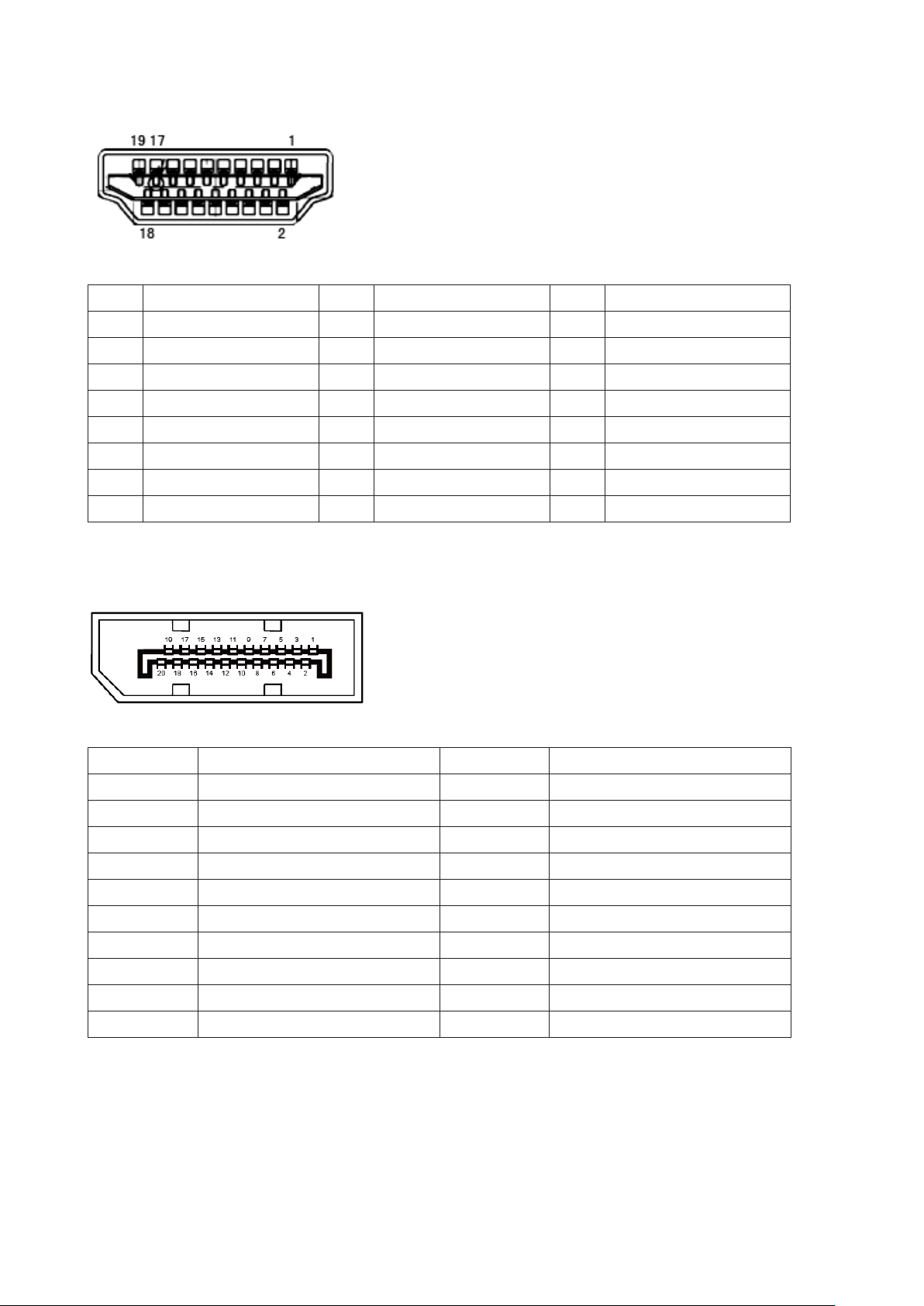
Pin Assignments
19-Pin Color Display Signal Cable
Pin No. Signal Name Pin No. Signal Name Pin No. Signal Name
1. TMDS Data 2+ 9. TMDS Data 0- 17. DDC/CEC Ground
2. TMDS Data 2 Shield 10. TMDS Clock + 18. +5V Power
3. TMDS Data 2- 11. TMDS Clock Shield 19. Hot Plug Detect
4. TMDS Data 1+ 12. TMDS Clock-
5. TMDS Data 1Shield 13. CEC
6. TMDS Data 1- 14. Reserved (N.C. on device)
7. TMDS Data 0+ 15. SCL
8. TMDS Data 0 Shield 16. SDA
20-Pin Color Display Signal Cable
Pin No. Signal Name Pin No. Signal Name
1 ML_Lane 3 (n) 11 GND
2 GND 12 ML_Lane 0 (p)
3 ML_Lane 3 (p) 13 CONFIG1
4 ML_Lane 2 (n) 14 CONFIG2
5 GND 15 AUX_CH(p)
6 ML_Lane 2 (p) 16 GND
7 ML_Lane 1 (n) 17 AUX_CH(n)
8 GND 18 Hot Plug Detect
9 ML_Lane 1 (p) 19 Return DP_PWR
10 ML_Lane 0 (n) 20 DP_PWR

32
Plug and Play
Plug & Play DDC2B Feature
This monitor is equipped with VESA DDC2B capabilities according to the VESA DDC STANDARD. It allows the monitor to
inform the host system of its identity and, depending on the level of DDC used, communicate additional information about
its display capabilities.
The DDC2B is a bi-directional data channel based on the I2C protocol. The host can request EDID information over the
DDC2B channel.