
ENGLISH
FRANÇAIS
PI485 Gateway(C, R)
LG Electronics Inc.
Manufacturer: LG Electronics Inc. Changwon 2nd factory, 84, Wanam-ro,
Seongsan-gu, Changwon-si, Gyeongsangnam-do, KOREA
Please read this installation manual completely before installing the product.
Installation work must be performed in accordance with the national wiring
standards by authorized personnel only.
Please retain this installation manual for future reference after reading it
thoroughly.
INSTALLATION MANUAL
AIR
CONDITIONER
www.lghavc.com
www.lg.com
Copyright © 2014 - 2021 LG Electronics Inc. All Rights Reserved.
3828A20365Q
Rev.01_072621

2 485 Gateway(C, R)
Table of Contents
3 IMPORTANT SAFETY INSTRUCTIONS
5 ACCESSORY PARTS
6 PART DESCRIPTION
6 PI485 GATEWAY(C), (R)
7 INSTALLATION GUIDE
7 Installation Steps (PI485 GATEWAY(C), (R))
8 DIP Switch Configuration
9 Advanced Lock Control Type
10 Central Controller Connection Diagram
11 Examples For Product Installation
TABLE OF CONTENTS
Important Safety Instructions
Installation Manual 3
ENGLISH
READ ALL INSTRUCTIONS BEFORE
USING THE APPLIANCE.
Always comply with the following
precautions to avoid dangerous situations
and ensure peak performance of your
product.
WARNING
It can result in serious injury or death when
the directions are ignored.
CAUTION
It can result in minor injury or product
damage when the directions are ignored.
WARNING
• Installation or repairs made by unqualified
persons can result in hazards to you and
others.
• Installation work must be performed in
accordance with the National Electric
Code by qualified and authorized
personnel only.
• The information contained in the manual is
intended for use by a qualified service
technician familiar with safety procedures
and equipped with the proper tools and
test instruments.
• Failure to carefully read and follow all
instructions in this manual can result in
equipment malfunction, property damage,
personal injury and/or death.
Installation
• Be sure to request to the service center or
installation specialty store when installing
products. It will cause fire or electric shock
or explosion or injury.
• Request to the service center or
installation specialty store when
reinstalling the installed product. It will
cause fire or electric shock or explosion or
injury.
• Do not disassemble, fix, and modify
products randomly. It will cause fire or
electric shock.
• Be sure to turn off power before
installation. It will cause electric shock.
• Installation work must be performed in
accordance with the national wiring
standards by authorized personnel only.
• Always perform grounding. Otherwise, it
may cause electrical shock.
• You need to use a safely insulated power
supply which follows IEC61558-2-6 anc
NEC Class2. If you do not follow, It may
cause fire, electric shock, explosion or
injury.
• Securely attach the electrical part cover to
Module. If the electric part cover of Module
is not attached securely, it could result in a
fire or electric shock due to dust, water,
etc.
• Make the connections securely so that the
outside force of the cable may not be
applied to the terminals. Inadequate
connection and fastening may generate
heat and cause a fire.
In-use
• Do not place flammable stuffs close to the
product. It will cause fire.
• Do not allow water to run into the product.
It will cause electric shock or breakdown.
• Do not give the shock to the product. It will
cause breakdown when giving the shock
to the product.
• Request to the service center or
installation specialty store when the
product becomes wet. It will cause fire or
electric shock.
• Do not give the shock using sharp and
pointed objects. It will cause breakdown by
damaging parts.
!
!
!
Important Safety Instructions
Important Safety Instructions
4 485 Gateway(C, R)
• Do not touch the board when the power is
connected. It can cause a fire, electric
shock, explosion, injury and problem to the
product.
• Unplug the unit if strange sounds, smell, or
smoke comes from it. Otherwise, it may
cause electrical shock or a fire.
• The appliance must only be supplied at
safety extra low voltage corresponding to
the marking on the appliance.
• This appliance is not intended to be
accessible to the general public.
CAUTION
In-use
• Do not clean using the powerful detergent
like solvent but use soft cloths. It will cause
fire or product deformation.
• Do not press the screen using powerful
pressure or select two buttons. It will
cause product breakdown or malfunction.
• Do not touch or pull the lead wire with wet
hands. It will cause product breakdown or
electric shock.
• This appliance is not intended for use by
persons (including children) with reduced
physical, sensory or mental capabilities, or
lack of experience and knowledge, unless
they have been given supervision or
instruction concerning use of the appliance
by a person responsible for their safety.
Children should be supervised to ensure
that they do not play with the appliance.
• This appliance can be used by children
aged from 8 years and above and persons
with reduced physical, sensory or mental
capabilities or lack of experience and
knowledge if they have been given
supervision or instruction concerning use
of the appliance in a safe way and
understand the hazards involved. Children
shall not play with the appliance. Cleaning
and user maintenance shall not be made
by children without supervision.
Installation
• If anyone other than a licensed
professional installs, repairs, or alters
LGElectronics air conditioning products,
the warranty is voided.
- All costs associated with repair are then
the full responsibility of the owner.
• Do not install the unit in potentially
explosive atmospheres.
!
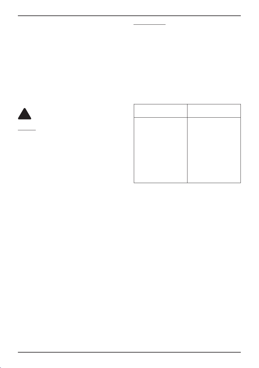
Minimum cross-sectional area of conductors
Rated current of appli-
ance A
Nominal cross-sectional
area mm
2
≤0.2
>0.2 and ≤3
>3 and ≤6
>6 and ≤10
>10 and ≤16
>16 and ≤25
>25 and ≤32
>32 and ≤40
>40 and ≤63
Tinsel cord
a
0.5
a
0.75
1.0 (0.75)
b
1.5 (1.0)
b
2.5
4
6
10
Accessory Parts
Installation Manual 5
ENGLISH
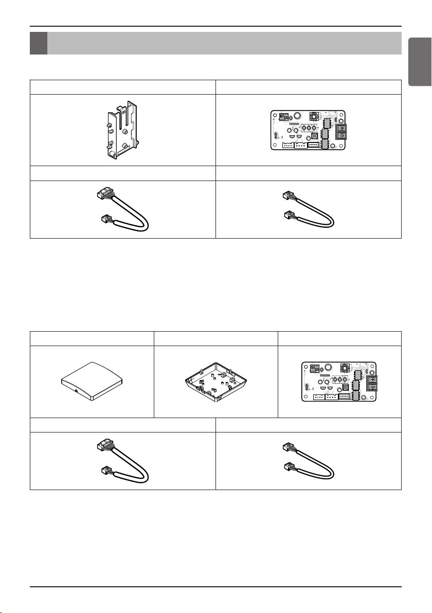
• PHNFP14A0(PI485 GATEWAY(C))
※ PCB is assembled in the rear case.
* Others :
Tie Wrap 3 EA - Cable Tie
Clamp 1 EA, Supporter 4 EA
Screw 4 EA (For installation)
Manual
Accessory Parts
Holder for DUCT PCB
L1 2 3 4
Cable 1 EA (For Connecting with indoor unit) Cable(for Others)
• PSNFP14A0(PI485 GATEWAY(R))
* Others :
Tie Wrap 3 EA - Cable Tie
Clamp 1 EA
Screw 6 EA (For installation)
Manual
Front Case Rear Case PCB
L1 2 3 4
Cable 1 EA (For Connecting with indoor unit) Cable(for Others)
6 485 Gateway(C, R)
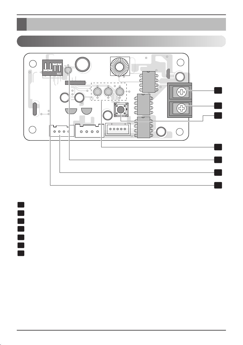
Part Description
BUS_B: RS-485 (-) Terminal
BUS_A: RS-485 (+) Terminal
Reset Switch: PI485(C) Reset
LED01G,02G,03G: Communication Status LED
LED1: RS-485 Communication Status LED
CN_OUT: Indoor Unit Connector
DIP Switch: Product Selection
1
2
4
5
6
7
3
L1 2 3 4
1
2
3
4
5
6
7
PI485 GATEWAY(C), (R)
Part Description

Installation Manual 7
Installation Guide
ENGLISH
1. Select DIP Switch Configuration
2. Connect RS-485 BUS_A(+), BUS_(B)(-) with other network products (ex.
Simple Central Controller , ACP.....)
3. Connect CN_OUT with Indoor Unit by the cable (provided)
4. Check the Communication Status LED
- LED1G(Red)
• OK operation : LED blinks for 5 times and then gets OFF
This process is repeated after every 3 minutes
• NG operation : Check the Indoor Unit°Øs address & wiring connections
- LED2G(Yellow), LED3G(Orange)
• NG operation : Check the DIP Switch setting & wiring connections
5. Check RS-485
n
OK operation :
(1) LED blinks when PI485 receives data from central controller.
n
NG operation : Check the wiring connections
6. Finally if all of the above steps are OK then tie the cables by tie wraps & clamp
6
7
4
5
1
2
Installation Steps (PI485 GATEWAY(C), (R))
Installation Guide
8 485 Gateway(C, R)
Installation Guide
L1 2
KSD42H
34
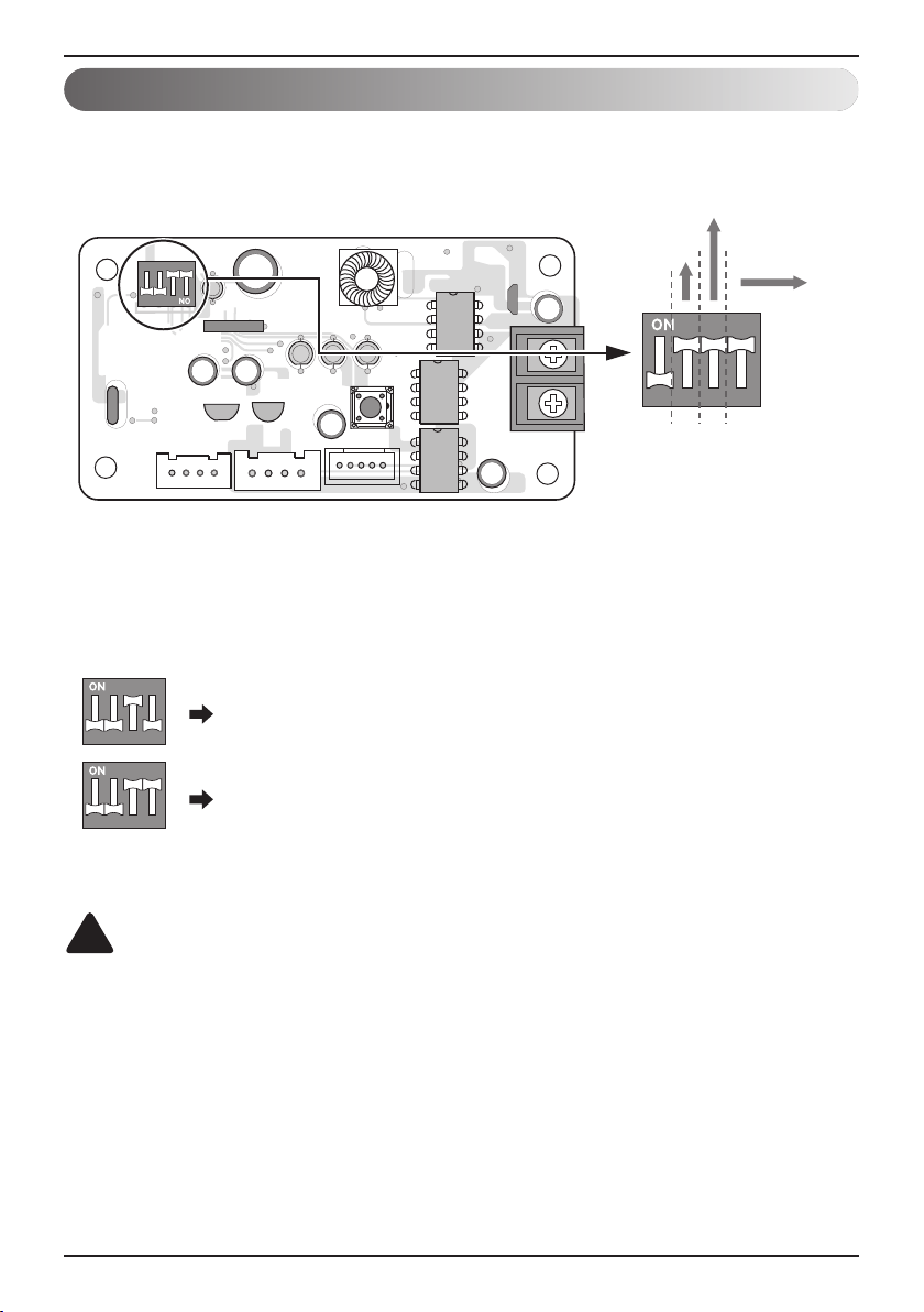
Select Air
Conditioner Type
Select Advanced
Control Type
Select Network
Type
L1 2 3 4
L1 2
KSD42H
34
L1 2
KSD42H
34
3 ON+ALL OFF: Using LGAP CAC Products + Central Controller
3, 4 ON+ALL OFF: LGAP CAC / Air Purifier Products + Central
Controller (ALL type)-Using LGAP
For CAC products using LGAP
h This means Central controller type (Central controller using LGAP is under development.
Next generation controller would use LGAP.)
• PI485 GATEWAY(C), (R)
CAUTION
Wrong products configuration can lead to malfunction.
The wrong setting of air-conditioner switch could cause malfunctioning.
Switch setting must be done carefully.
!
DIP Switch Configuration
Installation Manual 9
ENGLISH
Installation Guide
L1 2
KSD42H
34
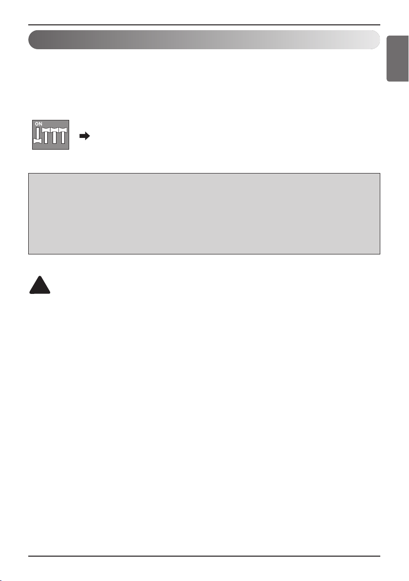
‘ 2,3,4 ON+All OFF : LGAP CAC/RAC/SRAC Products + Central
Controller (All types) - Using LGAP
- To use the advanced lock function (Run Mode lock, Fan Speed lock,
Temperature Lock, and Temperature Range lock; adjustable only within certain boundary)
by central controller, Set up the second DIP switch according to the type of outdoor
product.
- In case of advanced lock function, it can use only the central controller applied to LGAP.
CAUTION
The wrong setting of air-conditioner switch could cause malfunctioning.
Switch setting must be done carefully.
After setting the DIP switch, PI485 must be reset
!
NOTE : The advanced lock setting
Some products do not support advanced lock function.
In this case, The second DIP switch on PI485 must be on.
In case of product applied to advanced function, it can process the advanced lock function without second DIP
switch ON.
If all units support advanced lock function,
It is recommended that the second DIP switch be off, so that advanced lock function is processed faster.
Advanced Lock Control Type
Installation Guide
10 485 Gateway(C, R)
CAUTION
After product installation, tie the cables with the clamps & tie-wraps provided.
!
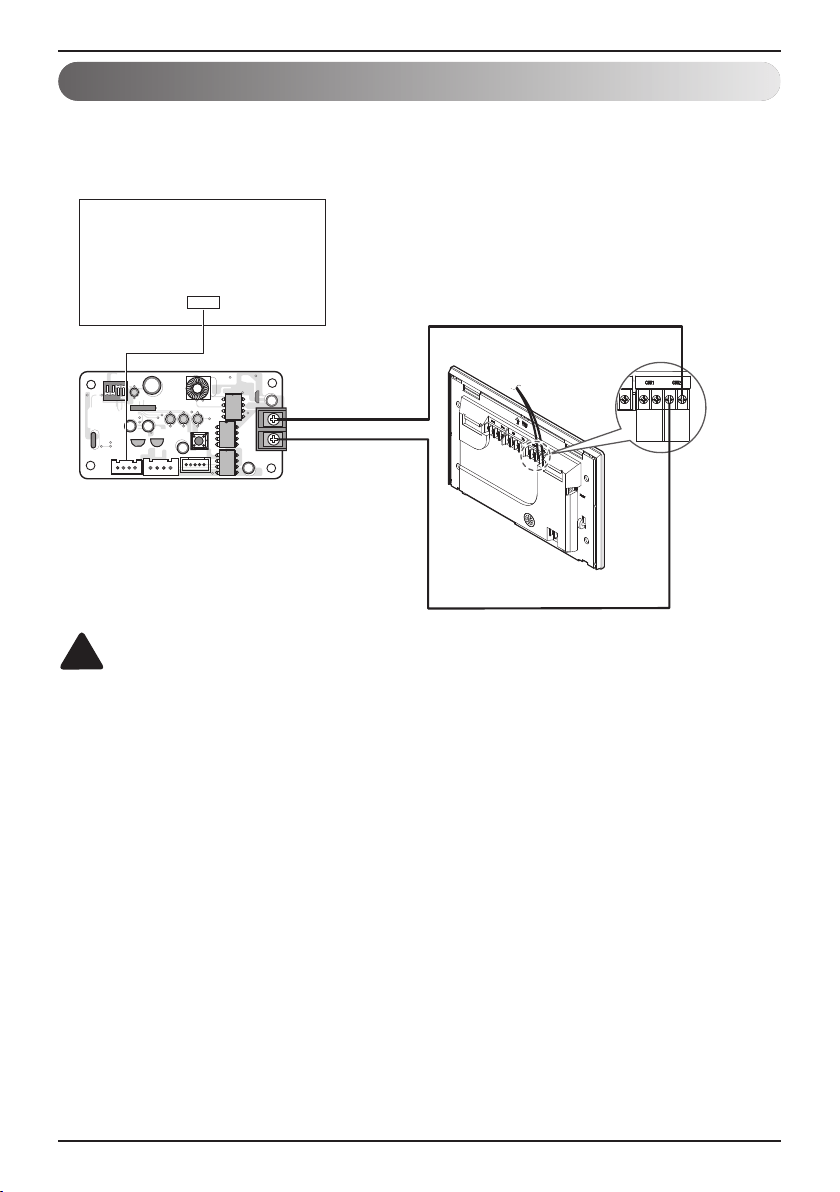
• PI485 GATEWAY(C), (R)
EX) AC Smart 5
AB
AHU
AB
(RS485)
ODU
CAC Indoor Unit / Air Purifier Main PCB
PI485 GATEWAY
L1 2 3 4
CN_CC(CAC)
CN_EXT_LIGHT(Air Purifier)
BUS_A
BUS_B
Central Controller Connection Diagram
Installation Manual 11
Installation Guide
ENGLISH
CAUTION
Installation location can be different depending upon product's structure.
!
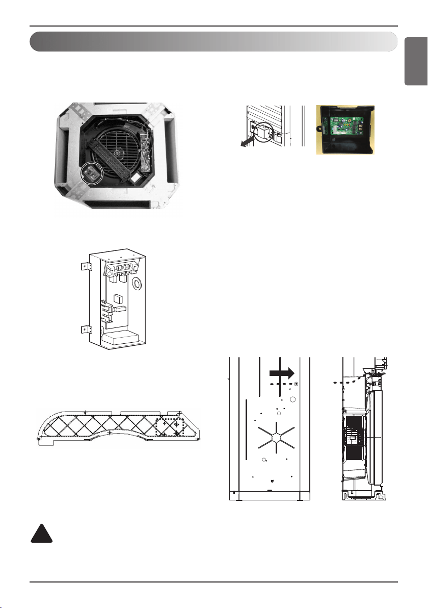
Examples For Product Installation
(1) The Installation for 4Way Cassette
Product
’ Check Screw boss for PCB in 4way
Cassette Product then fix it.
(2) The Installation for DUCT Product
’ Using PCB Holder provided
(3) The Installation for Cassette Product
Cover
’ Check Screw boss for PCB in 4way
Cassette Product Then fix It.
Remove the PCB cover after separating the
air inlet.
Install the PI485 PCB inside the PCB cover
as shown in the figure.
※Note : The harness for connecting the
PI485 PCB and the main PCB is
included with the air purifier
product.
Connect the communication line for
connecting the central controller and the
PI485 PCB through the hole on the rear
side.
※Note : Be careful not to allow the hole
knockout to enter into the product
when eliminating it for the
communication line.
※ Note : Apply the O type and the Y type
terminals for connecting the PI485
communication line.

12 485 Gateway(C, R)