Loading ...
Loading ...
Loading ...
12 — English
OPERATION
When storing the unit for a long period of time
(three months or longer) be sure the chain is lightly
lubricated; this will prevent rust on the chain and
bar sprocket.
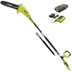
INSTALLING/REMOVING BATTERY
PACK
See Figure 6.
WARNING:
Always remove battery pack from your tool
when you are assembling parts, making adjust-
ments, cleaning, carrying, transporting or when
not in use. Removing battery pack will prevent
accidental starting that could cause serious
personal injury.
NOTE: To avoid serious personal injury, always
remove the battery pack and keep hands clear of
the lock-out button when carrying or transporting
the tool.
To install:
Place the battery pack in the pole saw. Align
raised rib on battery pack with groove in battery
port.
WARNING:
Make sure the latch on the battery pack snaps
in place and the battery pack is fully seated and
secure in the power head battery port before
beginning operation. Failure to securely seat
the battery pack could cause the battery pack
to fall out, resulting in serious personal injury.
To remove:
Depress the latch and remove the battery pack.
WARNING:
To avoid serious personal injury, always remove
the battery pack and keep hands clear of the
lock-out button when carrying or transporting
the tool.
For complete charging instructions, see the opera-
tor’s manuals for your battery pack and charger.
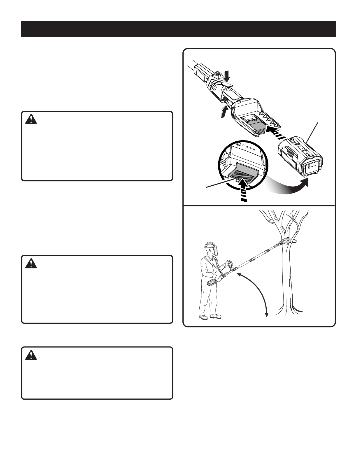
STARTING AND STOPPING
See Figures 6 - 7.
To start the motor:
Hold the pole saw as shown and ensure that you
are well away from anything that may contact
the blade.
Press and hold the trigger lock-out.
Depress the switch trigger.
To stop the motor:
Release the trigger to stop the pole saw. Upon
release of the trigger, the trigger lock will auto-
matically reset to the locked position.
Fig. 7
Fig. 6
LOCK-OUT
BUTTON
SWITCH
TRIGGER
BATTERY
LATCH
Loading ...
Loading ...
Loading ...