Use & Care Guide
Manual de Uso y Cuidado
English / Espa_ol
Models/Modelos: 148.16136110/148.16137110
I(enmoreo
@ @ @
P/N S3218A-Manual
Sears Brands Management Corporation
Hoffman Estates, IL 60179 U.S.A.
www.kenmore.com
www.sears.com
If you smell gas:
1. Shut off gas to the appliance.
2. Extinguishany open flame.
3. Open lid.
4. If odor continues, keep away from the
appliance and immediately call your gas
supplier or your fire department.
1. Do not store or use gasoline or other
flammable liquids or vapors in the vicinity
of this or any other appliance.
2. An LP cylinder not connectedfor use shall
not be stored in the vicinity of this or any
other appliance.
Installation Safety Precautions
• Use grill, as purchased, only with LP (propane) gas and the
regulator/valve assembly supplied. A conversion kit must
be purchased for use with natural gas.
• Grill installation must conform with local codes, or in their
absence of local codes, with either the National Fuel Gas
Code, ANSI Z223.1/NFPA 54, Natural Gas and Propane
Installation Code, CSA B149.1, or Propane Storage and
Handling Code, B149.2, or the Standard for Recreational
Vehicles,ANSI A 119.2/NFPA 1192, and CSA Z240 RV
Series, Recreational Vehicle Code, as applicable.
• All electrical accessories (such as rotisserie) must be
electrically grounded in accordance with local codes, or
National Electrical Code, ANSI/NFPA 70 or Canadian
Electrical Code, CSA C22.1. Keep any electrical cords
and/or fuel supply hoses away from any hot surfaces.
• This grill is safety certified for use in the United States
and/or Canada only. Do not modify for use in any other
location. Modification will result in a safety hazard.
Call Grill Service Center For Help And Parts
If you have questions or need assistance during assembly,
please call 1-800-482-0131.You will be speaking to a
representative of the grill manufacturerand not a Sears
employee. To order new parts call Sears at
1-800-4-MY-HOME.
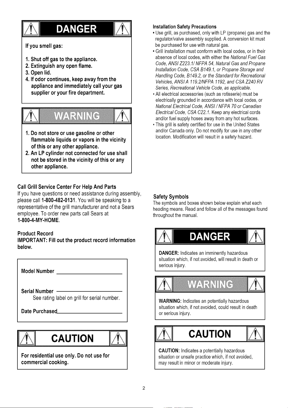
Safety Symbols
The symbols and boxes shown below explain what each
heading means. Read and follow all of the messages found
throughout the manual.
Product Record
IMPORTANT: Fill out the product record information
below.
Model Number
Serial Number
See rating label on grill for serial number.
Date Purchased
DANGER: Indicates an imminently hazardous
situation which, if not avoided, will result in death or
serious injury.
WARNING: Indicates an potentially hazardous
situation which, if not avoided, could result in death
or serious injury.
For residential use only. Do not use for
commercial cooking.
CAUTION: Indicates a potentially hazardous
situation or unsafe practice which, if not avoided,
may result in minor or moderate injury.

ForYourSafety.................................. 2
GrillServiceCenter............................... 2
ProductRecordInformation........................ 2
SafetySymbols.................................. 2
InstallationSafetyPrecautions....................... 2
KenmoreGrillWarranty........................... 3
UseandCare................................ 4-10
NaturalGasConversionBox...................... 11
Notes.......................................... 11
TransformerConnectionInstruction........................13-14
PartsList...................................... 15
Parts Diagram................................... 16
Assembly .................................... 17-29
Troubleshooting............................... 29-31
Repair Protection Agreements
Congratulations on making a smart purchase. Your new
Kenmore ®productis designed and manufactured for years of
dependable operation. But like all products, it may require
repair from time to time. That's when having a Repair
Protection Agreement can save you money and aggravation.
Purchase a Repair Protection Agreement now and protect
yourself from unexpected hassle and expense.
Here's what the Repair Protection Agreement includes:
[] Expert service by our 10,000 professional repair
specialists
[] Unlimited service and no charge for parts and labor on
all covered repairs
[] Product replacement up to $1500 if your covered
product can't be fixed
[] Discount of 10% from regular price of service and
related installed parts not covered by the agreement; also,
10% off regular price of preventive maintenance check
[] Fast help by phone - we call it Rapid Resolution -
phone support from a Sears representative. Think of us
as a "talking owner's manual."
Once you purchase the Repair Protection Agreement, a simple
phone call is all that it takes for you to schedule service. You
can call anytime day or night, or schedule a service
appointment online.
The Repair Protection Agreement is a risk-free purchase. If you
cancel for any reason during the product warranty period, we
will provide a full refund. Or, a prorated refund anytime after
the product warranty period expires. Purchase your Repair
Protection Agreement today!
Some limitations and exclusions apply.
For prices and additional information call 1-800-827-6655.
Sears Installation Service
For Sears professional installation of home appliances, garage
door openers, water heaters, and other major home items, in
the U.S.A. call 1-800-4-MY-HOME®
Kenmore Full Warranty
If this grill fails due to a defect in material or workmanship
within one year from the date of purchase, call 1-800-4-MY-
HOME® to arrange for free repair (or replacement if repair
proves impossible).
Limited Warranty on Burners
For ten years from the date of purchase, any stainless steel
burner that rusts through will be replaced free of charge. After
the first year from the date of purchase, you pay for labor if
you wish to have it installed.
All warranty coverage excludes ignitor batteries and grill part
paint loss, discoloration or rusting, which are either
expendable parts that can wear out from normal use within
the warranty period, or are conditions that can be the result
of normal use, accident or improper maintenance.
All warranty coverage is void if this grill is ever used for
commercial or rental purposes.
All warranty coverage applies only if this grill is used in the
United States.
This warranty gives you specific legal rights, and you may
also have other rights which vary from state to state.
Sears Brands Management Corporation,
Hoffman Estates, IL 60179
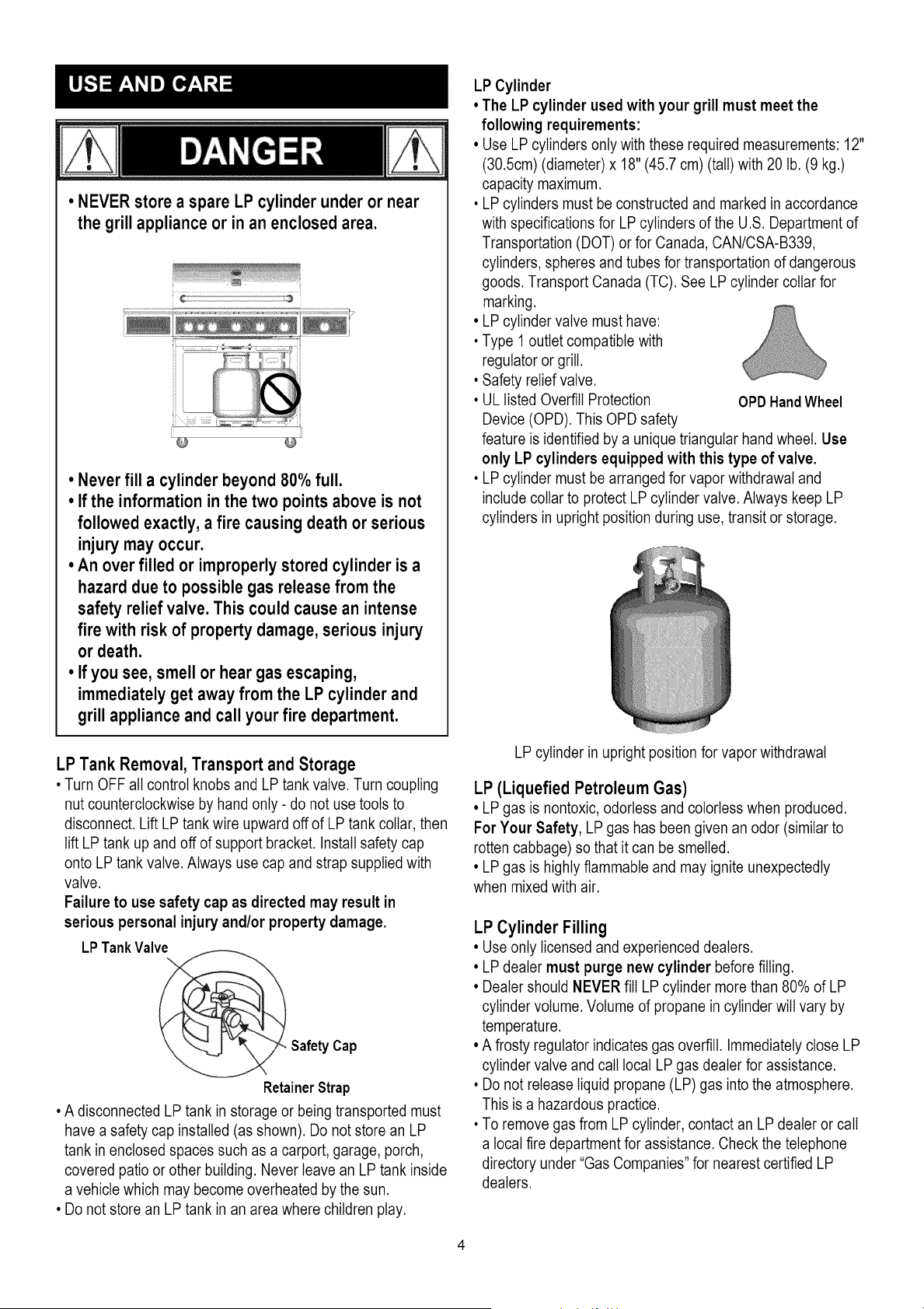
• NEVERstorea spareLPcylinderunderor near
thegrill applianceor in anenclosedarea.
• Never fill a cylinder beyond 80% full.
• If the information in the two points above is not
followed exactly, a fire causing death or serious
injury may occur.
• An over filled or improperly stored cylinder is a
hazard due to possible gas release from the
safety relief valve. This could cause an intense
fire with risk of property damage, serious injury
or death.
• If you see, smell or hear gas escaping,
immediately get away from the LP cylinder and
grill appliance and call your fire department.
LP Cylinder
• The LP cylinder used with your grill must meet the
following requirements:
• Use LP cylinders only with these required measurements: 12"
(30.5cm) (diameter) x 18" (45.7 cm) (tall) with 20 lb. (9 kg.)
capacity maximum.
• LP cylinders must be constructed and marked in accordance
with specifications for LP cylinders of the U.S. Department of
Transportation (DOT) or for Canada, CAN/CSA-B339,
cylinders, spheres and tubes for transportation of dangerous
goods. Transport Canada (TC). See LP cylinder collar for
marking.
• LP cylinder valve must have:
• Type 1 outlet compatible with
regulator or grill.
• Safety relief valve.
• UL listed Overfill Protection OPD HandWheel
Device (OPD). This OPD safety
feature is identified by a unique triangular hand wheel. Use
only LP cylinders equipped with this type of valve.
• LP cylinder must be arranged for vapor withdrawal and
include collar to protect LP cylinder valve. Always keep LP
cylinders in upright position during use, transit or storage.
LP Tank Removal, Transport and Storage
• Turn OFF all control knobs and LP tank valve. Turn coupling
nut counterclockwise by hand only - do not use tools to
disconnect. Lift LP tank wire upward off of LP tank collar, then
lift LP tank up and off of support bracket. Install safety cap
onto LP tank valve. Always use cap and strap supplied with
valve.
Failure to use safety cap as directed may result in
serious personal injury and/or property damage.
LPTankValve
@_ Safety Cap
RetainerStrap
• A disconnected LP tank in storage or being transported must
have a safety cap installed (as shown). Do not store an LP
tank in enclosed spaces such as a carport, garage, porch,
covered patio or other building. Never leave an LP tank inside
a vehicle which may become overheated by the sun.
• Do not store an LP tank in an area where children play.
LP cylinder in upright position for vapor withdrawal
LP (Liquefied Petroleum Gas)
• LP gas is nontoxic, odorless and colorless when produced.
For Your Safety, LP gas has been given an odor (similar to
rotten cabbage) so that it can be smelled.
• LP gas is highly flammable and may ignite unexpectedly
when mixed with air.
LP Cylinder Filling
• Use only licensed and experienced dealers.
• LP dealer must purge new cylinder before filling.
• Dealer should NEVER fill LP cylinder more than 80% of LP
cylinder volume. Volume of propane in cylinder will vary by
temperature.
• A frosty regulator indicates gas overfill. Immediately close LP
cylinder valve and call local LP gas dealer for assistance.
• Do not release liquid propane (LP) gas into the atmosphere.
This is a hazardous practice.
• To remove gas from LP cylinder, contact an LP dealer or call
a local fire department for assistance. Check the telephone
directory under "Gas Companies" for nearest certified LP
dealers.
LP Tank Exchange
•Many retailers that sell grills offer you the option of replacing
your empty LP tank through an exchange service. Use only
those reputable exchange companies that inspect, precision
fill, test and certify their cylinders. Exchange your tank only
for an OPD safety feature-equipped tank as described in
the "LP Tank" section of this manual.
•Always keep new and exchanged LP tanks in upright position
during use, transit or storage.
,Leak test new and exchanged LP tanks BEFORE
connecting to grill.
LP Tank Leak Test
Foryoursafety
•Leak test must be repeated each time LP tank is exchanged
or refilled.
•Do not smoke during leak test.
•Do not use an open flame to check for gas leaks.
•Grill must be leak tested outdoors in a well-ventilated area,
away from ignition sources such as gas fired or electrical
appliances. During leak test, keep grill away from open
flames or sparks.
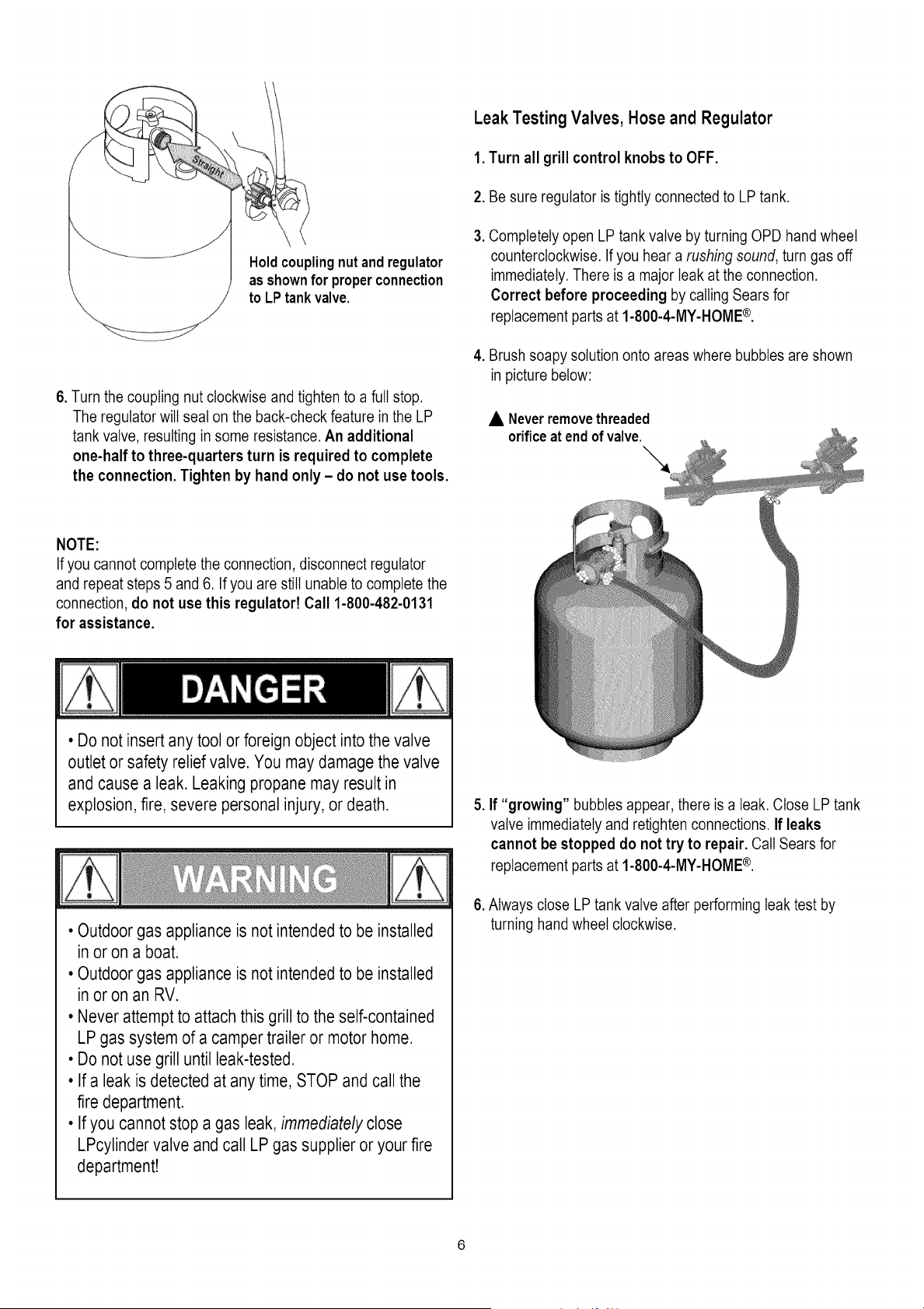
•Use a clean paintbrush and a 50/50 mild soap and water
solution. Brush soapy solution onto areas indicated by arrows
infigure below. Leaks are indicated by growing bubbles.
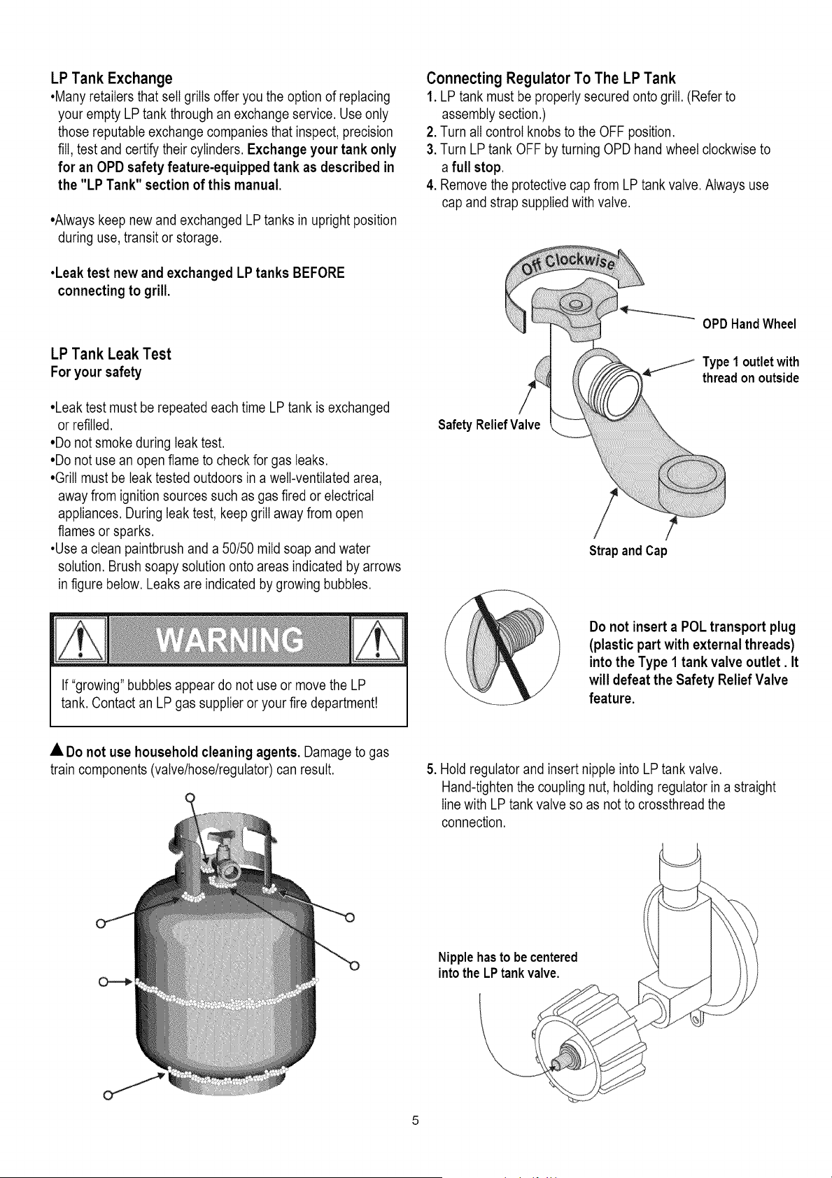
Connecting Regulator To The LP Tank
1. LP tank must be properly secured onto grill. (Refer to
assembly section.)
2. Turn all control knobs to the OFF position.
3. Turn LP tank OFF by turning OPD hand wheel clockwise to
a full stop.
4. Remove the protective cap from LP tank valve. Always use
cap and strap supplied with valve.
OPD HandWheel
._ Type1 outletwith
threadon outside
Safety ReliefValve
/
Strap and Cap
If "growing" bubbles appear do not use or move the LP
tank. Contact an LP gas supplier or your fire department!
Do not insert a POL transport plug
(plastic part with external threads)
into the Type 1 tank valve outlet. It
will defeat the Safety Relief Valve
feature.
• Do not use household cleaning agents. Damage to gas
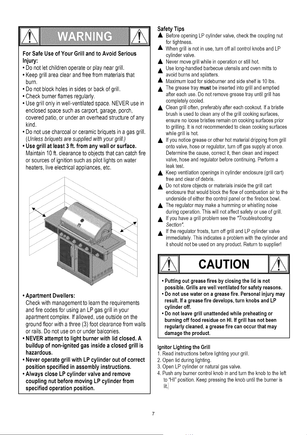
train components (valve/hose/regulator) can result. 5. Hold regulator and insert nipple into LP tank valve.
Hand-tighten the coupling nut, holding regulator in a straight
linewith LP tank valve so as not to crossthread the
connection.
Nipplehasto be centered
into the LPtank valve.
Holdcouplingnut andregulator
as shownfor properconnection
to LPtankvalve.
6. Turn the coupling nut clockwise and tighten to a full stop.
The regulator will seat on the back-check feature in the LP
tank valve, resulting in some resistance. An additional
one-half to three-quarters turn is required to complete
the connection. Tighten by hand only - do not use tools.
Leak Testing Valves, Hose and Regulator
1.Turnall grillcontrolknobsto OFF.
2. Be sure regulator is tightly connected to LP tank.
.
Completely open LP tank valve by turning OPD hand wheel
counterclockwise. If you hear a rushing sound, turn gas off
immediately. There is a major leak at the connection.
Correct before proceeding by calling Sears for
replacement parts at 1-800-4-MY-HOME®.
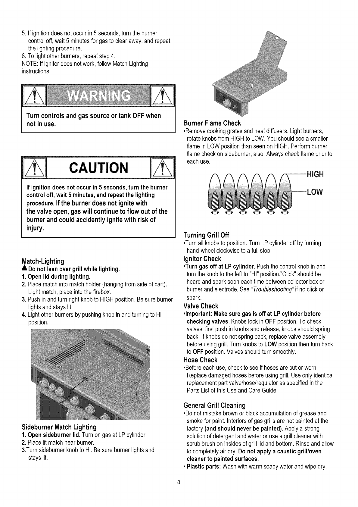
4. Brush soapy solution onto areas where bubbles are shown
in picture below:
• Neverremovethreaded
orificeat endof valve.
NOTE:
If you cannot complete the connection, disconnect regulator
and repeat steps 5 and 6. If you are still unable to complete the
connection, do not use this regulatort Call 1-800-482-0131
for assistance.
• Do not insert any tool or foreign object into the valve
outlet or safety relief valve. You may damage the valve
and cause a leak. Leaking propane may result in
explosion,fire, severe personal injury, or death.
• Outdoor gas appliance is not intended to be installed
in or on a boat.
• Outdoor gas appliance is not intended to be installed
in or on an RV.
• Never attempt to attach this grill to the self-contained
LP gas system of a camper trailer or motor home.
• Do not use grill until leak-tested.
• If a leak is detected at any time, STOP and call the
fire department.
• If you cannot stop a gas leak, immediately close
LPcylinder valve and call LP gas supplier or your fire
department!
5. If "growing" bubbles appear, there is a leak. Close LP tank
valve immediately and retighten connections. If leaks
cannot be stopped do not try to repair. Call Sears for
replacement parts at 1-800-4-MY-HOME®.
6. Always close LP tank valve after performing leak test by
turning hand wheel clockwise.
For Safe Use of Your Grill and to Avoid Serious
Injury:
• Do not let children operate or play near grill.
• Keep grill area clear and free from materials that
burn.
• Do not block holes in sides or back of grill.
• Check burnerflames regularly.
• Use grill only in well-ventilated space. NEVER use in
enclosed space such as carport, garage, porch,
covered patio, or under an overhead structure of any
kind.
• Do not use charcoal or ceramic briquets in a gas grill.
(Unless briquets are supplied with your grill.)
• Use grill at least 3 ft. from any wall or surface.
Maintain 10 ft. clearance to objects that can catch fire
or sources of ignition such as pilot lights on water
heaters, live electrical appliances, etc.
• Apartment Dwellers:
Check with management to learn the requirements
and fire codes for using an LP gas grill in your
apartment complex. If allowed, use outside on the
ground floor with a three (3) foot clearance from walls
or rails. Do not use on or under balconies.
° NEVER attempt to light burner with lid closed. A
buildup of non-ignited gas inside a closed grill is
hazardous.
• Never operate grill with LP cylinder out of correct
position specified in assembly instructions.
• Always close LP cylinder valve and remove
coupling nut before moving LP cylinder from
specified operation position.
Safety Tips
• Before opening LP cylinder valve, check the coupling nut
for tightness.
• When grill is not in use, turn off all control knobs and LP
cylinder valve.
• Never move grill while in operation or still hot.
• Use long-handled barbecue utensils and oven mitts to
avoid burns and splatters.
• Maximum load for sideburner and side shelf is 10 Ibs.
• The grease tray must be inserted into grill and emptied
after each use. Do not remove grease tray until grill has
completely cooled.
• Clean grill often, preferably after each cookout. If a bristle
brush is used to clean any of the grill cooking surfaces,
ensure no loose bristles remain on cooking surfaces prior
to grilling. It is not recommended to clean cooking surfaces
while grill is hot.
• If you notice grease or other hot material dripping from grill
onto valve, hose or regulator, turn off gas supply at once.
Determine the cause, correct it, then clean and inspect
valve, hose and regulator before continuing. Perform a
leak test.
• Keep ventilation openings in cylinder enclosure (grill cart)
free and clear of debris.
• Do not store objects or materials inside the grill cart
enclosure that would block the flow of combustion air to the
underside of either the control panel or the firebox bowl.
• The regulator may make a humming or whistling noise
during operation. This will not affect safety or use of grill.
• If you have a grill problem see the "Troubleshooting
Section".
• If the regulator frosts, turn off grill and LP cylinder valve
immediately. This indicates a problem with the cylinder and
it should not be used on any product. Return to supplier!
CAUTION
• Putting out grease fires by closing the lid is not
possible. Grills are well ventilated for safety reasons.
• Do not use water on a grease fire. Personal injury may
result. If a grease fire develops, turn knobs and LP
cylinder off.
• Do not leave grill unattended while preheating or
burning off food residue on HI. If grill has not been
regularly cleaned, a grease fire can occur that may
damage the product.
Ignitor Lighting the Grill
1. Read instructions before lighting your grill.
2. Open lid during lighting.
3. Open LP cylinder or natural gas valve.
4. Push any burner control knob in and turn the knob to the left
to "HI" position. Keep pressing the knob until the burner is
lit.I
5.Ifignitiondoesnotoccurin5seconds,turntheburner
controloff,wait5minutesforgastoclearaway,andrepeat
thelightingprocedure.
6.Tolightotherburners,repeatstep4.
NOTE:Ifignitordoesnotwork,followMatchLighting
instructions.
Turn controls and gas source or tank OFF when
not in use.
If ignitiondoesnot occurin5 seconds,turnthe burner
controloff,wait5 minutes,and repeatthe lighting
procedure.If the burner does not ignite with
the valve open, gas will continue to flow out of the
burner and could accidently ignite with risk of
injury.
Match-Lighting
• Do not lean over grill while lighting.
1. Open lid during lighting.
2. Place match into match holder (hanging from side of cart).
Light match, place into the firebox.
3. Push in and turn right knob to HIGH position. Be sure burner
lights and stays Iit.
4. Light other burners by pushing knob in and turning to HI
position.
Sideburner Match Lighting
1. Open sideburner lid. Turn on gas at LP cylinder.
2. Place Iit match near burner.
&Turn sideburner knob to HI. Be sure burner lights and
stays Iit.
Burner Flame Check
,Remove cooking grates and heat diffusers. Light burners,
rotate knobs from HIGH to LOW. You should see a smaller
flame in LOW position than seen on HIGH. Perform burner
flame check on sideburner, also. Always check flame prior to
each use.
_ _ _2_ _ 8 ¸
Turning GrillOff
•Turn all knobs to position. Turn LP cylinder off by turning
hand-wheel clockwise to a full stop.
Ignitor Check
•Turn gas off at LP cylinder. Push the control knob in and
turn the knob to the left to "HI" position."Click" should be
heard and spark seen each time between collector box or
burner and electrode. See "Troubleshooting" if no click or
spark.
Valve Check
•Important: Make sure gas is off at LP cylinder before
checking valves. Knobs lock in OFF position. To check
valves, first push in knobs and release, knobs should spring
back. If knobs do not spring back, replace valve assembly
before using grill. Turn knobs to LOW position then turn back
to OFF position. Valves should turn smoothly.
Hose Check
•Before each use, check to see if hoses are cut or worn.
Replace damaged hoses before using grill. Use only identical
replacement part valve/hose/regulator as specified in the
Parts List of this Use and Care Guide.
General Grill Cleaning
•Do not mistake brown or black accumulation of grease and
smoke for paint. Interiors of gas grills are not painted at the
factory (and should never be painted). Apply a strong
solution of detergent and water or use a grill cleaner with
scrub brush on insides of grill lid and bottom. Rinse and allow
to completely air dry. Do not apply a caustic grill/oven
cleaner to painted surfaces.
• Plastic parts: Wash with warm soapy water and wipe dry.
Donotusecitrisot,abrasivecleaners,degreasersora
concentratedgrillcleaneronplasticparts.Damagetoand
failureofpartscanresult.
•Porcelainsurfaces:Becauseofglass-likecomposition,most
residuecanbewipedawaywithbakingsoda/watersolutionor
speciallyformulatedcleaner.Usenonabrasivescouring
powderforstubbornstains.
*Painted surfaces: Wash with mild detergent or nonabrasive
cleaner and warm soapy water. Wipe dry with a soft
nonabrasive cloth.
•Stainless steel surfaces: To maintain your grill's high quality
appearance, wash with mild detergent and warm soapy water
and wipe dry with a soft cloth after each use. Baked-on
grease deposits may require the use of an abrasive plastic
cleaning pad. Use only in direction of brushed finish to avoid
damage. Do not use abrasive pad on areas with graphics.
• Cooking surfaces: If a bristle brush is used to clean any of
the grill cooking surfaces, ensure no loose bristles remain on
cooking surfaces prior to grilling. It is not recommended to
clean cooking surfaces while grill is hot.
Storing Your Grill
•Clean cooking grates.
•Store in dry location.
•When LP cylinder is connected to grill, store outdoors in a
wellventilated space and out of reach of children.
•Cover grill if stored outdoors. Choose from a variety of grill
covers offered by manufacturer.
•Store grill indoors ONLY if LP cylinder is turned off and
disconnected, removed from grill and stored outdoors.
•When removing grill from storage, follow "Cleaning the Burner
Assembly' instructions before starting grill.
Cleaning the Burner Assembly
Follow these instructions to clean and/or replace parts of
burner assembly or if you have trouble igniting grill.
1. Turn gas off at control knobs and LP cylinder.
2. Remove cooking grates and heat diffusers.
3. Remove R pins from rear of burners.
4. Carefully Iift each burner up and away from valve openings.
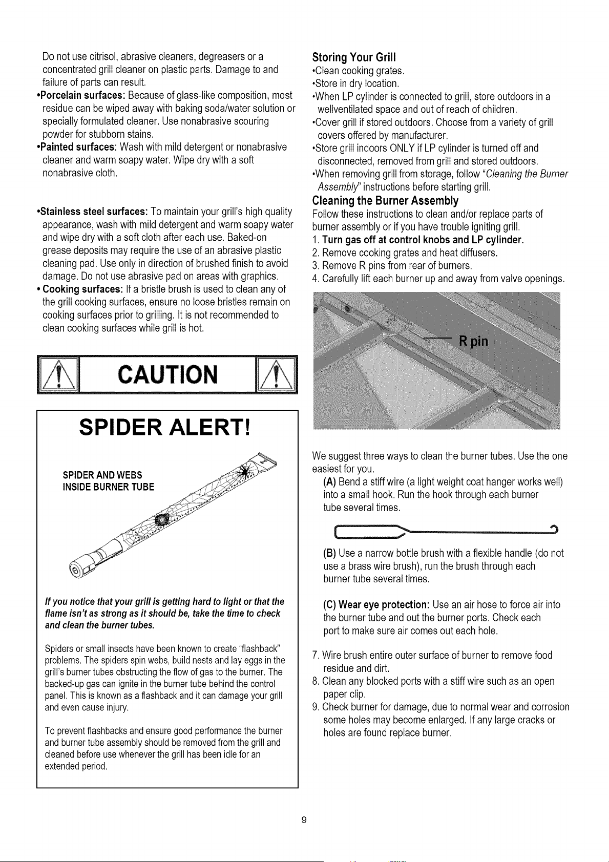
SPIDER ALERT!
If you notice that your grill is getting hard to light or that the
flame isn't as strong as it should be, take the time to check
and clean the burner tubes.
Spidersorsmallinsectshavebeenknownto create"flashback"
problems.Thespidersspinwebs,build nestsandlayeggsin the
grill's burnertubes obstructingthe flowof gasto the burner.The
backed-upgas canignitein the burnertube behindthe control
panel.Thisis knownas a flashbackandit can damageyourgrill
and evencauseinjury.
To preventflashbacksand ensuregoodperformancethe burner
and burnertube assemblyshouldberemovedfrom the grill and
cleanedbeforeusewheneverthe grillhas beenidle for an
extendedperiod,
We suggest three ways to clean the burner tubes. Use the one
easiest for you.
(A) Bend a stiff wire (a light weight coat hanger works well)
into a small hook. Run the hook through each burner
tube several times.
'3
(B) Use a narrow bottle brush with a flexible handle (do not
use a brass wire brush), run the brush through each
burner tube several times.
(C) Wear eye protection: Use an air hose to force air into
the burner tube and out the burner ports. Check each
port to make sure air comes out each hole.
7. Wire brush entire outer surface of burner to remove food
residue and dirt.
8. Clean any blocked ports with a stiffwire such as an open
paper clip.
9. Check burner for damage, due to normal wear and corrosion
some holes may become enlarged. If any large cracks or
holes are found replace burner.
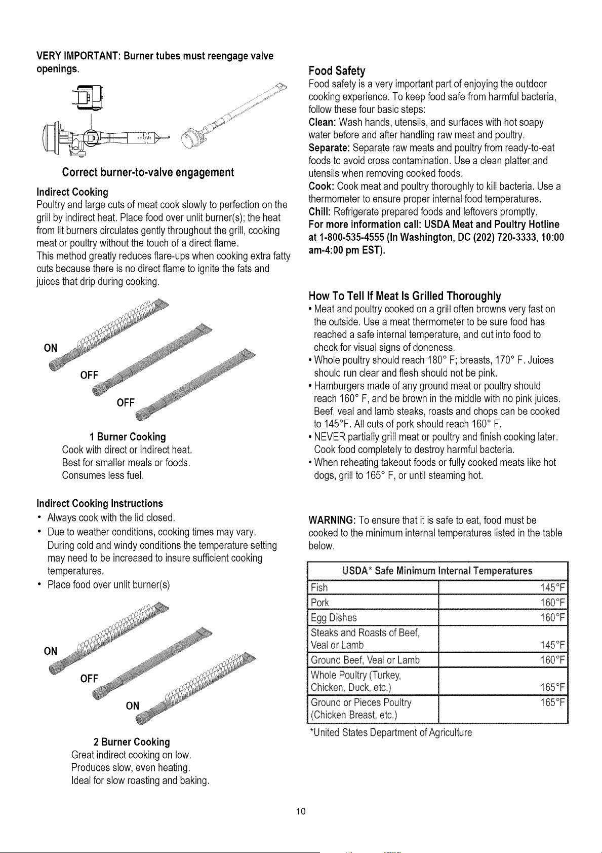
VERY IMPORTANT: Burner tubes must reengage valve
openings.
Correct burner-to-valve engagement
Indirect Cooking
Poultry and large cuts of meat cook slowly to perfection on the
grill by indirect heat. Place food over unlit burner(s); the heat
from lit burners circulates gently throughout the grill, cooking
meat or poultry without the touch of a direct flame.
This method greatly reduces flare-ups when cooking extra fatty
cuts because there is no direct flame to ignite the fats and
juices that drip during cooking.
1 Burner Cooking
Cook with direct or indirect heat.
Best for smaller meals or foods.
Consumes less fuel.
Indirect Cooking Instructions
• Always cook with the lid closed.
• Due to weather conditions, cooking times may vary.
During cold and windy conditions the temperature setting
may need to be increased to insure sufficient cooking
temperatures.
• Place food over unlit burner(s)
2 Burner Cooking
Great indirect cooking on low.
Produces slow, even heating.
Ideal for slow roasting and baking.
Food Safety
Food safety is a very important part of enjoying the outdoor
cooking experience. To keep food safe from harmful bacteria,
follow these four basic steps:
Clean: Wash hands, utensils, and surfaces with hot soapy
water before and after handling raw meat and poultry.
Separate: Separate raw meats and poultry from ready-to-eat
foods to avoid cross contamination. Use a clean platter and
utensils when removing cooked foods.
Cook: Cook meat and poultry thoroughly to kill bacteria. Use a
thermometer to ensure proper internal food temperatures.
Chill: Refrigerate prepared foods and leftovers promptly.
For more information call: USDA Meat and Poultry Hotline
at 1-800-535-4555 (In Washington, DC (202) 720-3333, 10:00
am-4:00 pm EST).
How To Tell If Meat Is Grilled Thoroughly
• Meat and poultry cooked on a grill often browns very fast on
the outside. Use a meat thermometer to be sure food has
reached a safe internal temperature, and cut into food to
check for visual signs of aloneness.
• Whole poultry should reach 180° F; breasts, 170° F. Juices
should run clear and flesh should not be pink.
• Hamburgers made of any ground meat or poultry should
reach 160° F, and be brown in the middle with no pink juices.
Beef, veal and lamb steaks, roasts and chops can be cooked
to 145°F. All cuts of pork should reach 160° F.
• NEVER partially grill meat or poultry and finish cooking later.
Cook food completely to destroy harmful bacteria.
• When reheating takeout foods or fully cooked meats like hot
dogs, grill to 165° F, or until steaming hot.
WARNING: To ensure that it is safe to eat, food must be
cooked to the minimum internal temperatures listed in the table
below.
USDA* Safe Minimum Internal Temperatures
Fish 145°F
Pork 160°F
Egg Dishes 160°F
Steaks and Roasts of Beef,
Vealor Lamb 145°F
Ground Beef, Veal or Lamb 160°F
Whole Poultry (Turkey,
Chicken, Duck, etc.) 165°F
Ground or Pieces Poultry 165°F
(Chicken Breast, etc.)
*United States Departmentof Agriculture
10
To purchase Natural Gas Conversion Parts call Sears at
1.800.4.MY.HOME ®
Natural gas conversion kit
Kenmore Model# 10478
(Manufacturer Part No.: S3218A-KIT)
Your grill can be converted to natural gas with this
conversion kit by a qualified gas technician only. In order
to convert this grill the technician will need this
conversion kit.
The kit contains orifices for various grill models. Please
select the orifices as listed below and discard the rest.
Follow the conversion instruction provided with the kit.
Model Main burner
¢1.37
Sideburner
¢1.37
Rear burner
¢1.40
[ ]
[]
148.16136110 5 1 1
148.16137110
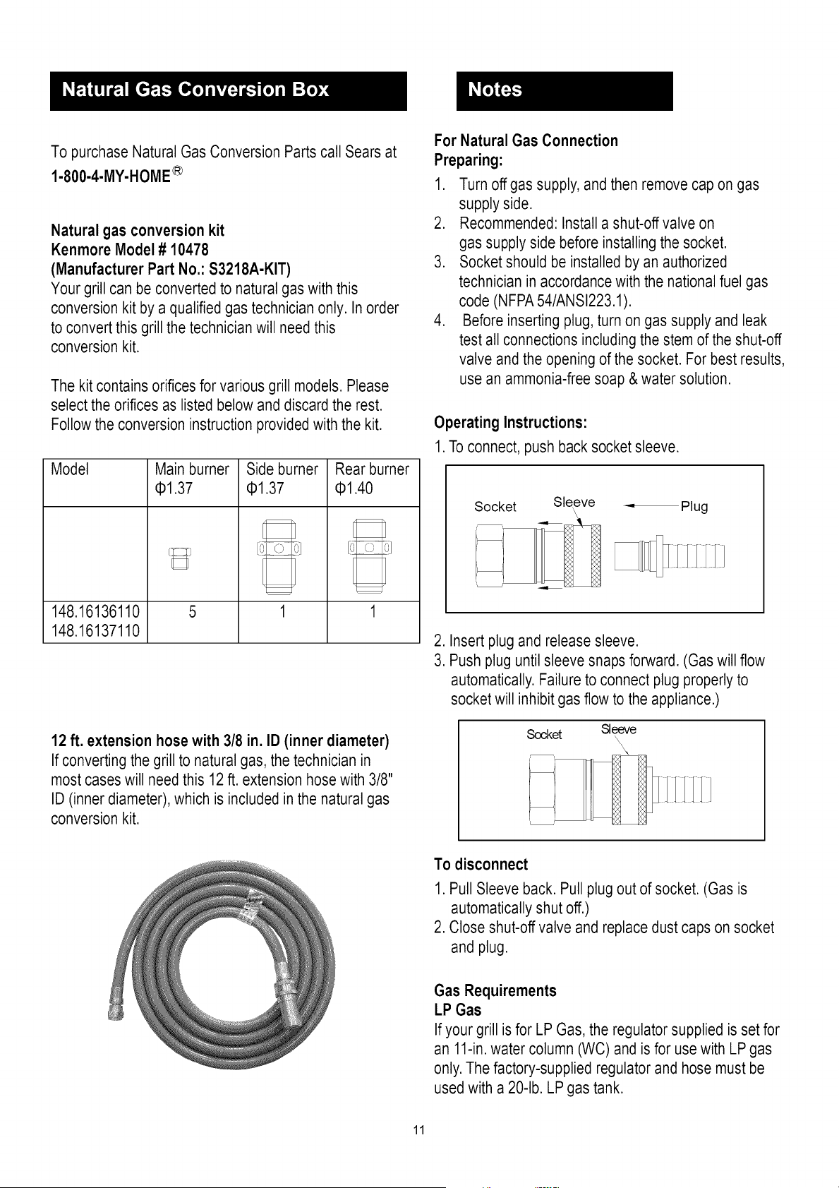
12 ft. extension hose with 3/8 in. ID (inner diameter)
If converting the grill to natural gas, the technician in
most cases will need this 12 ft. extension hose with 3/8"
ID (inner diameter), which is included in the natural gas
conversion kit.
For Natural Gas Connection
Preparing:
1. Turn off gas supply, and then remove cap on gas
supply side.
2. Recommended: Install a shut-off valve on
gas supply side before installing the socket.
3. Socket should be installed by an authorized
technician in accordance with the national fuel gas
code (NFPA54/ANSI223.1).
4. Before inserting plug, turn on gas supply and leak
test all connections including the stem of the shut-off
valve and the opening of the socket. For best results,
use an ammonia-free soap & water solution.
Operating Instructions:
1. To connect, push back socket sleeve.
Socket Sleeve = Plug
\
- fq IIIIIJ
2. Insert plug and release sleeve.
3. Push plug until sleeve snaps forward. (Gas will flow
automatically.Failure to connect plug properly to
socket will inhibit gas flow to the appliance.)
Soc,ket Sleeve
f
To disconnect
1. Pull Sleeve back. Pull plug out of socket. (Gas is
automatically shut off.)
2. Close shut-off valve and replace dust caps on socket
and plug.
Gas Requirements
LP Gas
If your grill is for LP Gas, the regulator supplied is set for
an 11-in.water column (WC) and is for use with LP gas
only. The factory-supplied regulator and hose must be
used with a 20-lb. LP gas tank.
11

Natural Gas
If your grill is for Natural Gas, it is set for a 7-in. water
column (WC) and is for use with Natural Gas only. Gas
pressure is affected by gas line size and the length of
gas line run from house gas line. Follow the
recommendations in the chart below.
From House to Grill
Distance Tubing Size
Up to 25 ft. 3/8 in. diameter
26-50 ft. 1/2 in. diameter
2/3 of the run: 3/4 in. diameter
51-100 ft.
1/3of the run :1/2 in. diameter
Over 101 ft. 3/4 in. diameter
Helpful Care and Maintenance Hints
Before grilling, pre-heat grill for 15 minutes on "HI" with
hood down. To avoid uncontrolledflare-ups or grease
fires, grill meats with hood open. Close hood if meats are
thick or weather is cold, or if you are using a rotisserie or
indirect cooking.
Always protect your hand with a pot holder or cooking
glove when coming into contact with a hot surface.
Hood up when grilling meats, especially chicken. Hood
down when indirect or rotisserie cooking.
NEVER leave your grill unattendedwhile cooking.
After use, close hood, turn burnersto HIfor 15 min. for
self-cleaning, grease burn off.
Excess Flow Control and Low Heat
The propane regulator assembly incorporatesan excess
flow device designed to supply the grill with sufficient gas
flow under normal conditions yet control excess gas flow.
Rapid changes in pressure can trigger the excessflow
device providing a low flame and low temperature. If the
tank valve is turned open to allow gas flow while a burner
valve is open, the surge of pressurewill cause the device
to activate. The device will remain closed until the
pressure is equalized. This should occur within 5
seconds.
To ensure this does not cause difficulty in lighting the grill,
follow these instructions:
1. Make sure all burner valves are "OFF".
2. Open the tank valve and wait 5 seconds.
3. Light the burners one at a time following the lighting
instructions.
Care and Maintenance Time TableChart
Grill Item FrequencyBased
on Normal Use CleaningMethod
Paintedsurface Twiceyearly Car wax
Stainlesssurface Twiceyearly Stainlesscleaner
All grates Aftereach use Burn off andwipe
Wire brush/
Stainlessgrates 15days Dishwashersafe
Scrub padsoapywater
Porcelaingrates 15days /Dishwashersafe
Burnerheat tents 30 days Wire brush
Burners 90 days Wire brush
Burnerbox Interiorgrill cleaning
120days products(availableat
interior sears)
12

For your safety the $3218A grill comes equipped with a
UL approved transformerfor outdoor use that provides
low voltage to power 10-wattgrill lights featured with this
model.
Light Operation Instruction
1. Make sure light's power switch on the control
panel is in the "OFF" position.
2. Connect power plug to properlygrounded outlet.
3. Turn the light's power switch to "ON".
All wiring is factory connected except the easy
connection you must make: connect the factory wire to
the transformer with a provided screw-on plastic
connector.
Keep any electrical supply cord away from any
heated surface.
Do not turn on the lights when the hood is closed.
Connector
Light Wire
Pull the factory wire through the opening in the rear panel,
plug the transformer in any household outlet.
Bulb Replacement
INSTRUCTIONSPERTAININGTO A RISK OF FIRE,
ELECTRIC SHOCK, EXPOSURETO EXCESSIVE UV
RADIATION,OR INJURYTO PERSONS
IMPORTANTSAFETY INSTRUCTIONS
Lighted lamp is HOT:
WARNING -TO REDUCETHE RISK OF FIRE,
ELECTRIC SHOCK, EXPOSURETO EXCESSIVE UV
RADIATION,OR INJURYTO PERSONS:
1. Turn off/unplug and allow to cool before
replacing bulb (lamp).
2. Bulb (lamp) gets HOT quickly! Only contact
switch/plug when turning on.
3. Do not touch hot lens, guard, or enclosure. (+)
4. Do not remain in light if skin feels warm.
5. Do not look directly at lighted lamp.
6. Keep lampaway from materials that may burn.
7. Use only with 10-watt or smaller bulbs (lamps).
8. Do not touch the bulb (lamp) at any time. Use a
soft cloth. Oil from skin may damage bulb (lamp).
9. Do not operate the portable luminaries with a
missing or damaged guard, lamp containment
barrier, or UVfilter. (+)
13
Remarks:
(+) Guard - Guard is a portion of portable luminaries unit
that prevents inadvertent contact with the bulb. It may be
integral with the UV filter or lamp containment barrier or
as part of enclosure or shade.
(+) Lamp containment barrier-lamp containment barrier
is a portion of a portable luminaries unit that encloses the
bulb.
(+) UV filter- UV filter is a portion of a portable
luminaries unit hat limits ultraviolet (UV) emissions.
.
Make sure the light's power switch on the control
panel is in the "OFF" position and power plug is
disconnected from outlet.
. Use a screwdriver to loosen the screw which is
securing the burner box rear panel.
Buring this process, hold the Lamp class;
otherwise, it will fall and break, potentially
causing bodily harm.
Lamp class
/_ -"-- Screw Here
3. Remove the Lamp class.
Lamp class
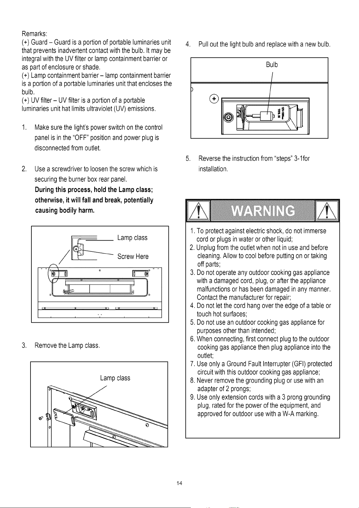
4. Pull out the light bulb and replace with a new bulb.
.
Bulb
®
/
Reverse the instruction from "steps" 3-1for
installation.
1. To protect against electricshock, do not immerse
cord or plugsin water or other liquid;
2. Unplug from the outlet when not in use and before
cleaning. Allow to cool before putting on or taking
off parts;
3. Do not operate any outdoor cooking gas appliance
with a damaged cord, plug, or after the appliance
malfunctions or has been damaged in any manner.
Contact the manufacturer for repair;
4. Do not let the cord hang over the edge of a table or
touch hot surfaces;
5. Do not use an outdoor cooking gas appliancefor
purposes other than intended;
6. When connecting, first connect plug to the outdoor
cooking gas appliancethen plug appliance into the
outlet;
7. Use only a Ground Fault Interrupter (GFI) protected
circuit with this outdoor cooking gas appliance;
8. Never remove the grounding plug or usewith an
adapter of 2 prongs;
9. Use only extension cords with a 3 prong grounding
plug, rated for the power of the equipment, and
approved for outdoor usewith a W-A marking.
14
Key
I
2
8
4
5
6
7
8
9
I0
11
12
18
14
15
16
17
18
19
2O
21
22
28
24
25
26
27
28
29
86
81
82
33
84
85
86
37
88
89
4O
41
42
Qty
I
2
I
I
I
5
8
I
5
5
I
I
I
I
I
2
I
I
2
2
I
2
I
2
I
I
I
I
I
I
I
I
I
I
I
I
I
I
I
6
6
I
Description
HOOD HANDLE
HANDLE BASE
HOOD
TEMPERATURE GAUGE
WASHER
R-PIN
COOKING GRID ( MAIN BURNER )
WARMING RACK
HEAT DIFFUSER
MAIN BURNER
IGNITION PIN ( MAIN BURNER )
IGNITION PIN ( MAIN BURNER )
IGNITION PIN ( MAIN BURNER )
IGNITION PIN ( MAIN BURNER )
IGNITION PIN ( MAIN BURNER )
RUBBER PLUG
SIDE SHELF
COLLECT BOX
5/16-18 UNC x I"
HOOD SLEEVE
BURNER BOX
LAMP SCREEN
REAR BURNER HOSE
BULB
REAR HOOD
REAR BURNER
IGNITION PIN ( REAR BURNER )
SIDE HOOD HANDLE
SIDE HOOD
SIDE BURNER GRID
SIDE BURNER SHAFT
SIDE BURNER SHELF
BOTTLE OPENER
SIDE BURNER
SIDE DRIP TRAY
IGNITION PIN ( SIDE BURNER )
SIDE BURNER HOSE
ELECTRICAL IGNITOR
SIDE BURNER VALVE
BEZEL
KNOB
LP GAS PRESSURE REGULATOR
Manufacturer
Part#
3218LT-00-4300
S3218AR-OO-4601
S3218AROO-4100
E3518-00-8802
E3518-00-4609
R-PIN
L3218-00-2010
L3218-00-2020
L3218-00-2001
SH3118B-2004
P3018-00-8804
P3018-00-8805
P3018-00-8806
L3218-00-8807
3218LT-00-8803
3219B-8882
S3218AR(AB)-OO-5100
E3518-00-5002
SCREW& NUT
E3518-OO-OOO1
S3218AR-OO-2000
E3520-80-8817
P3018-00-8815
L3218-00-8821
L3218-00-2426
L3218-00-8809
3218LT-00-8808
3218LT-00-2884
3218LT-00-2882
3218LT-00-2846
E3518-00-6002
S3218AR(AB)-OO-6100
SH3118B-5018
P3018-00-8808
P3018-OO-6010
S3218AR-OO-8002
S3218AR-OO-8005
L3218-00-8802
S3218AR-OO-6600
E3518-00-3002
E3518-00-3001
L3218-00-8806
Key
43
44
45
46
47
48
49
50
51
52
53
54
55
56
57
58
59
60
61
62
63
64
65
66
67
68
69
70
71
72
73
74
Qty Description
I MAIN BURNER HOSE
I MANIFOLD
2 SWITCH
I REAR BURNER BEZEL
I REAR BURNER KNOB
I IGNITION WIRE
I PANEL LIGHT WIRE
I CONTROL BOX
I BEAM
I DRIP TRAY
I DRIP TRAY SUPPORT
I TANK RING
I TANK RING BRACKET
I REAR PANEL
I HAND IGNITOR
I TRANSFORMER
I RIGHT PANEL
I SIDE PANEL BRACKET (RIGHT)
2 LOCKING CASTER
I BOTTOM PANEL
2 CASTER
2 MAGNET
I TANK SUPPORT
I RIGHT DOOR
I DOOR HANDLE
I LEFT DOOR
I SIDE PANEL BRACKET (LEFT)
I LEFT PANEL
I BATTERY BOX
2 TANK STOPPER
I SIDE BURNER LIGHT WIRE
I SIDE BURNER ORIFICE
I HARDWARE PACK
I PRODUCT MANUAL
Manufacturer
Part#
P3018-00-8821
S3218AR-OO-3200
E3520-00-8815
L3218-00-3062
L3218-00-3061
S3218AR-OO-8001
S3218AR-OO-8013
S3218AR(AB)-OO-3100
S3218AR-OO-1500
P3018-OO-1002
P3018-OO-1900
P3018-00-1203
E3518-00-1202
S3218AR-OO-1200
3019L-1718
S3218AR-OO-8003
S3218AR-OO-1300
L3018S-OO-1020
L3218-00-8813
S3218AR-06-1110
L3218-00-8812
L3018S-06-1310
L3218-00-1126
S3218AR(AB)-OO-1880
L3018S-OO-1410
S3218AR(AB)-OO-1700
L3018S-OO-1010
S3218AR-OO-1460
3218LT-00-8814
E3520-00-1050
S3218AR-OO-8015
P3018-OO-8808-A
S3218A-
HARDWARE
S3218A-
MANUAL
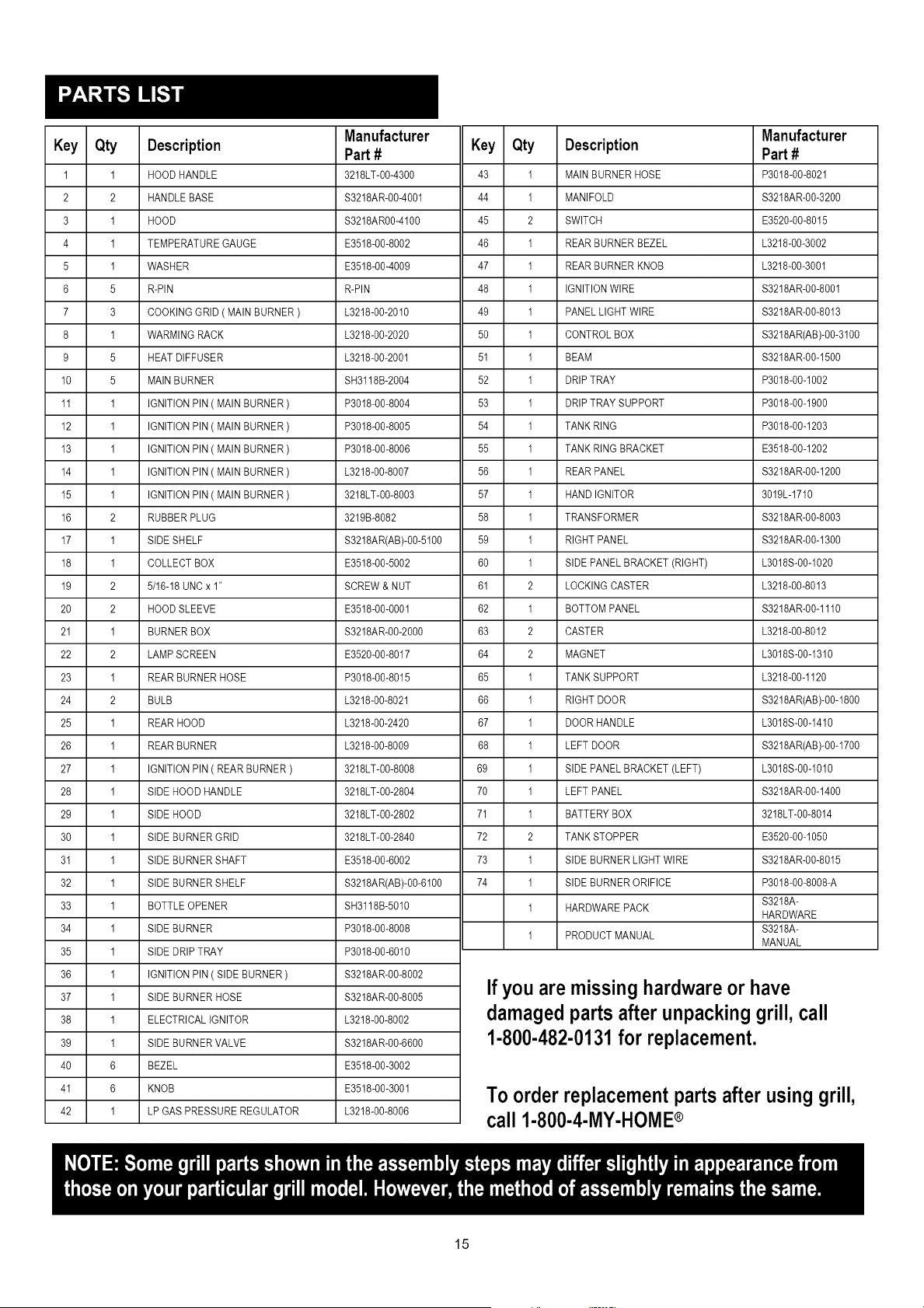
If you are missing hardwareor have
damagedparts after unpackinggrill, call
1-800-482-0131for replacement.
To order replacementparts after using grill,
r'_ll I.RNN.A.MY.Nr'IMP®
15
@
® ®
® ©
%
@
/
® @ @ G
18
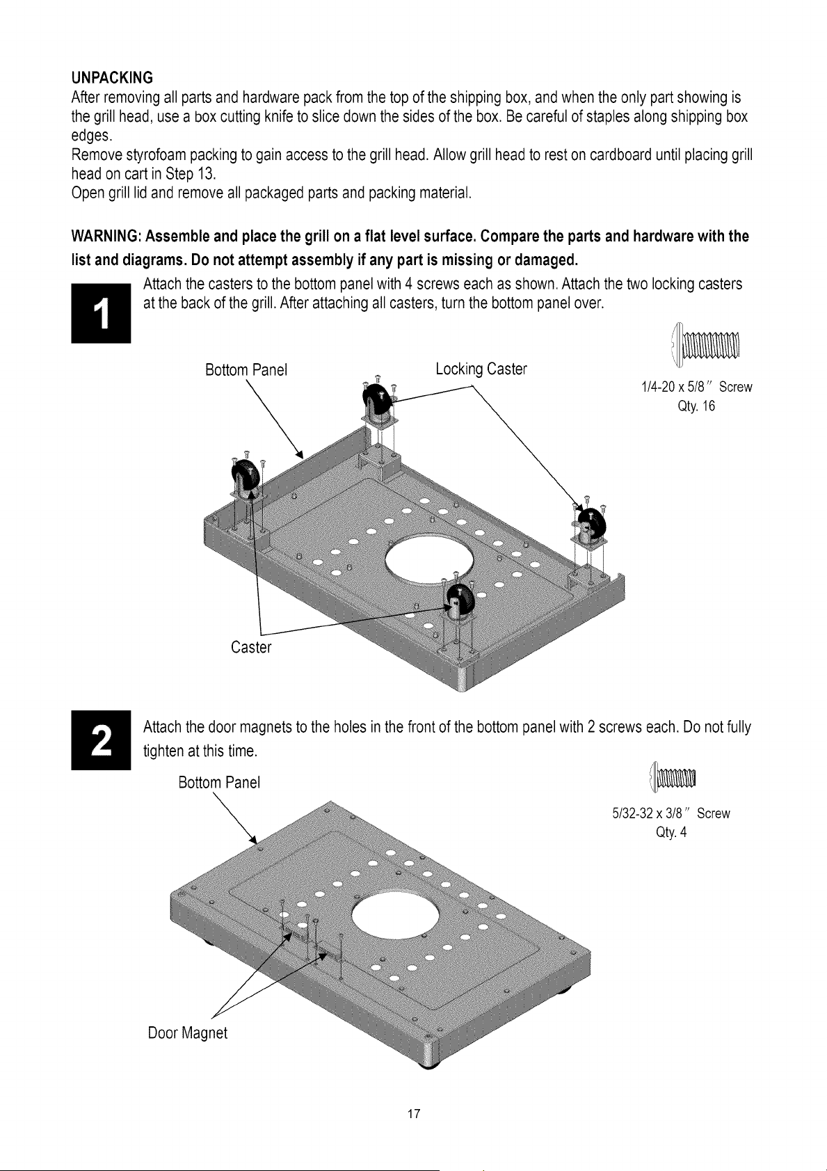
UNPACKING
After removing all parts and hardware pack from the top of the shipping box, and when the only part showing is
the grill head, use a box cutting knife to slice down the sides of the box. Be careful of staples along shipping box
edges.
Remove styrofoam packing to gain access to the grill head. Allow grill head to rest on cardboard until placing grill
head on cart in Step 13.
Open grill lid and remove all packaged parts and packing material.
WARNING: Assemble and place the grill on a flat level surface. Compare the parts and hardwarewith the
list and diagrams. Do not attempt assembly if any part is missing or damaged.
Attach the casters to the bottom panel with 4 screws each as shown.Attach the two locking casters
at the back of the grill. After attaching all casters, turn the bottom panel over.
Bottom Panel
Locking Caster
1/4-20x 5/8" Screw
Qty. 16
Caster
Attach the door magnets to the holes in the front of the bottom panel with 2 screws each. Do notfully
tighten at this time.
Bottom Panel !/I_
5/32-32 x 3/8" Screw
Qty.4
Door Magnet
17
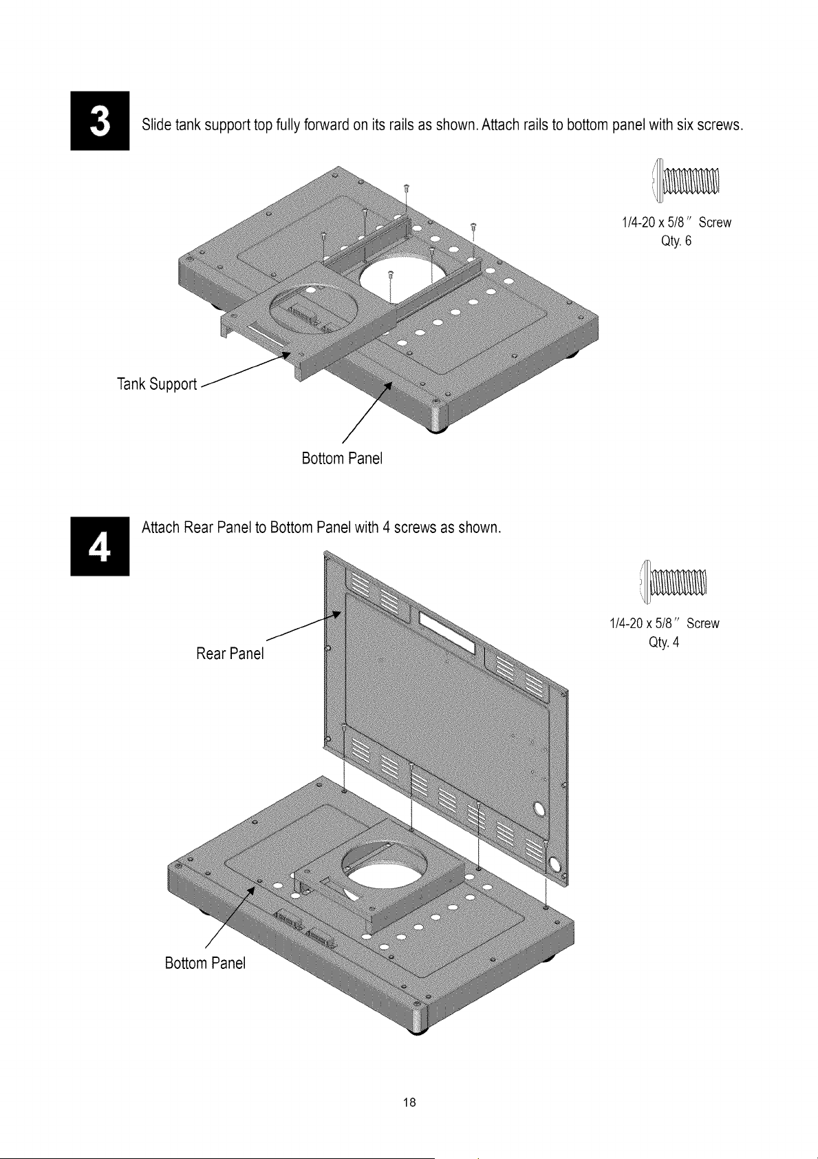
Slide tank support top fully forward on its rails as shown. Attach rails to bottom panel with six screws.
1/4-20 x 5/8" Screw
Qty.6
TankSupport
Bottom Panel
Attach Rear Panel to Bottom Panel with 4 screws as shown.
Rear Panel
Bottom Panel
1/4-20x 5/8" Screw
Qty.4
18
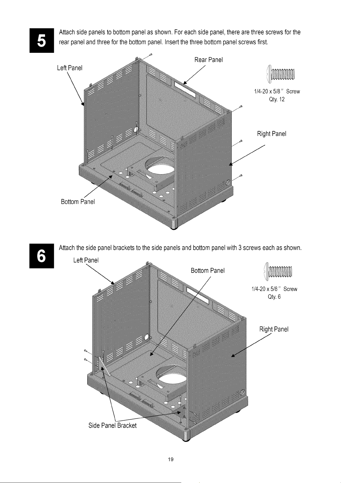
Attach side panels to bottom panel as shown. For each side panel, there are three screws for the
rear panel and three for the bottom panel. Insertthe three bottom panel screws first.
Left Panel
Bottom Panel
Rear Panel
1/4-20x 5/8" Screw
Qty. 12
Right Panel
Attach the side panel brackets to the side panels and bottom panel with 3 screws each as shown.
Left Panel
Bottom Panel
1/4-20x 5/8" Screw
Qty. 6
Right Panel
Side Panel Bracket
19
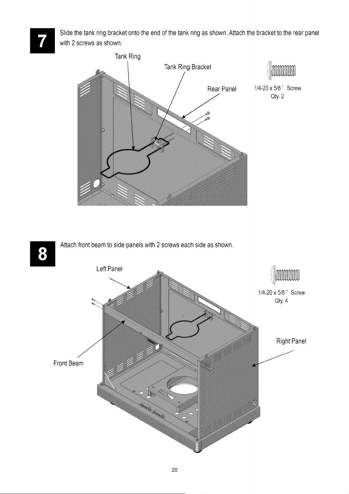
Slide the tank ring bracket onto the end of the tank ring as shown.Attach the bracket to the rear panel
with 2 screws as shown.
Tank Ring
Tank Ring Bracket
Rear Panel
1/4-20 x 5/8" Screw
Qty.2
Attach front beam to side panels with 2 screws each side as shown.
Le_ Panel
1/4-20x 5/8" Screw
Qty. 4
Right Panel
Front Beam
20
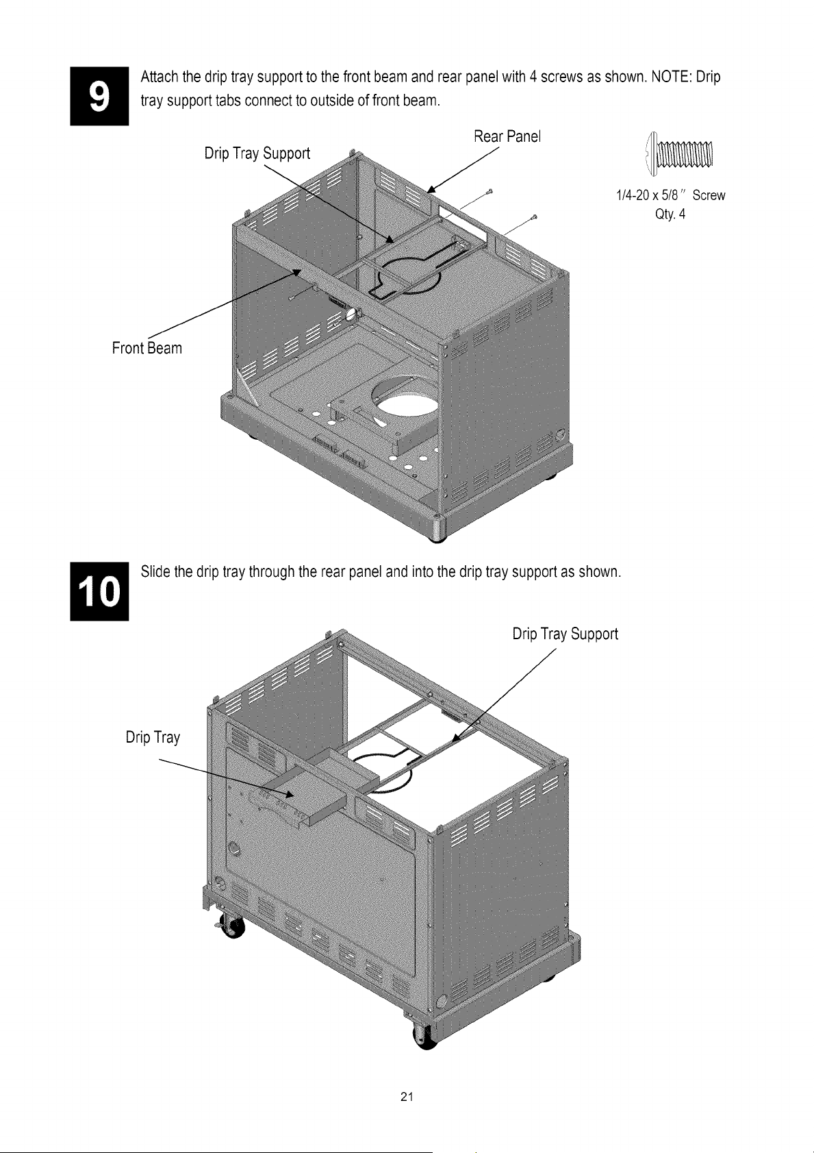
Attach the drip tray support to the front beam and rear panel with 4 screws as shown. NOTE: Drip
tray support tabs connect to outside of front beam.
Rear Panel
Drip Tray Support
1/4-20 x 5/8" Screw
Qty.4
Front Beam
Slide the drip tray through the rear panel and into the drip tray support as shown.
Drip Tray Support
Drip Tray
21
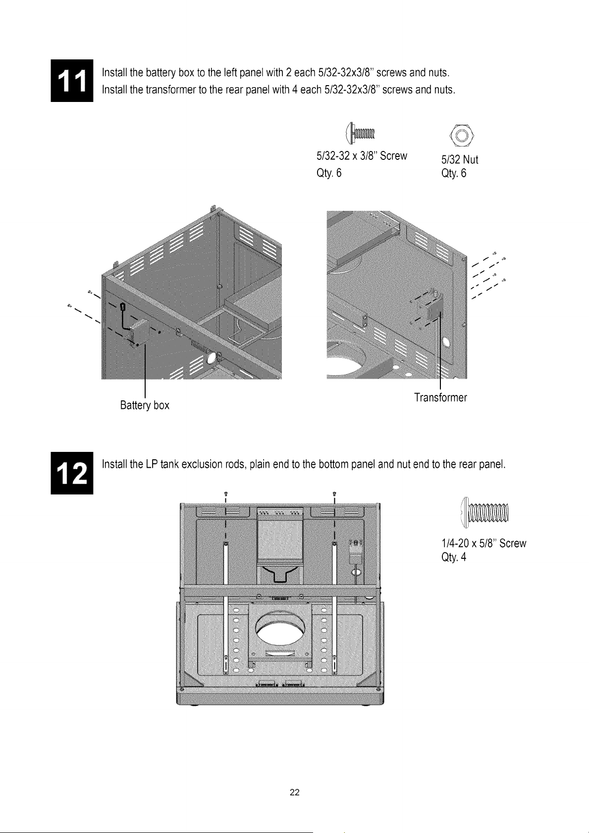
Install the battery box to the left panel with 2 each 5/32-32x3/8" screws and nuts.
Install the transformer to the rear panel with 4 each 5/32-32x3/8" screws and nuts.
Battery box
5/32-32 x 3/8" Screw 5/32 Nut
Qty. 6 Qty. 6
Transformer
f
J i
I
s i
I
/
Install the LP tank exclusion rods, plain end to the bottom panel and nut end to the rear panel.
1/4-20 x 5/8" Screw
Qty.4
22
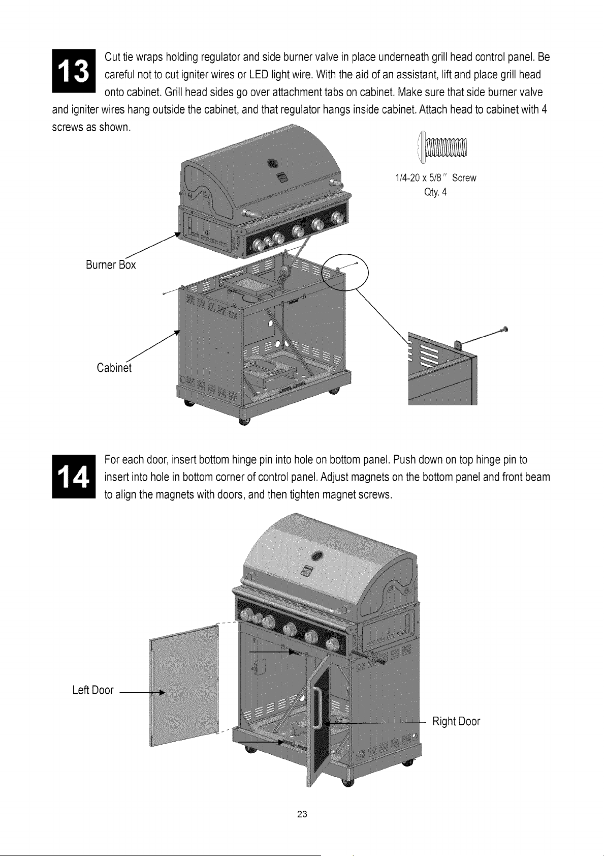
Cut tie wraps holding regulator and side burner valve in place underneath grill head control panel. Be
careful not to cut igniterwires or LED light wire. With the aid of an assistant, lift and place grill head
onto cabinet. Grill head sides go over attachment tabs on cabinet. Make sure that side burner valve
and igniterwires hang outside the cabinet, and that regulator hangs inside cabinet.Attach head to cabinet with 4
screws as shown.
1/4-20x 5/8" Screw
Qty.4
Burner Box
Cabinet
For each door, insert bottom hinge pin into hole on bottom panel. Push down on top hinge pin to
insert into hole in bottom corner of control panel.Adjust magnets on the bottom panel and front beam
to align the magnets with doors, and then tighten magnet screws.
Left Door --
Right Door
23

Loosen the four screws attached to the left panel of the burner box 3 to 4 turns as shown. Hangthe
side shelf by the slotted holes in its side onto the four loosened screws. Open the grill lid and use the
1/4-20 x 5/4" screw to fasten the side shelf from the inside of the burner box as shown. Tighten the
four previously loosened screws.
Loosen 1/4-20x 5/4" Screw
Qty. 1
Side Shelf
Side Burner Shelf
Loosen the four screws attached in the right panel of the burner box 3 to 4 turns as shown. Hang the
side burner shelf by the slotted holes in its side onto the four loosened screws. Open the grill lid and
use the 1/4-20 x 5/4" screw to fasten the side burner shelf from the inside of the burner box as shown.
Tighten the four previously loosened screws.Attach bottle opener to side burner shelf with 2 screws
as shown.
Loosen
3/16-24 x 1/2 "Screw 1/4-20 x 5/4" Screw
Qty.2 Qty.1
Side Burner Shelf
Bottle Opener
24
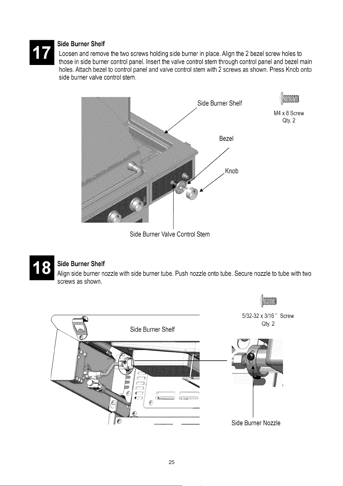
Side Burner Shelf
Loosen and remove the two screws holding side burner in place.Align the 2 bezel screw holes to
those in side burner control panel. Insertthe valve control stem through control panel and bezel main
holes. Attach bezelto control panel and valve control stem with 2 screws as shown. Press Knob onto
side burner valve control stem.
Side Burner Shelf
M4 x 8 Screw
Qty.2
Bezel
Side BurnerValve Control Stem
Side Burner Shelf
Align side burner nozzle with side burner tube. Push nozzle onto tube. Secure nozzle to tube with two
screws as shown.
Side Burner Shelf
5/32-32x 3/16" Screw
Qty.2
Side Burner Nozzle
25
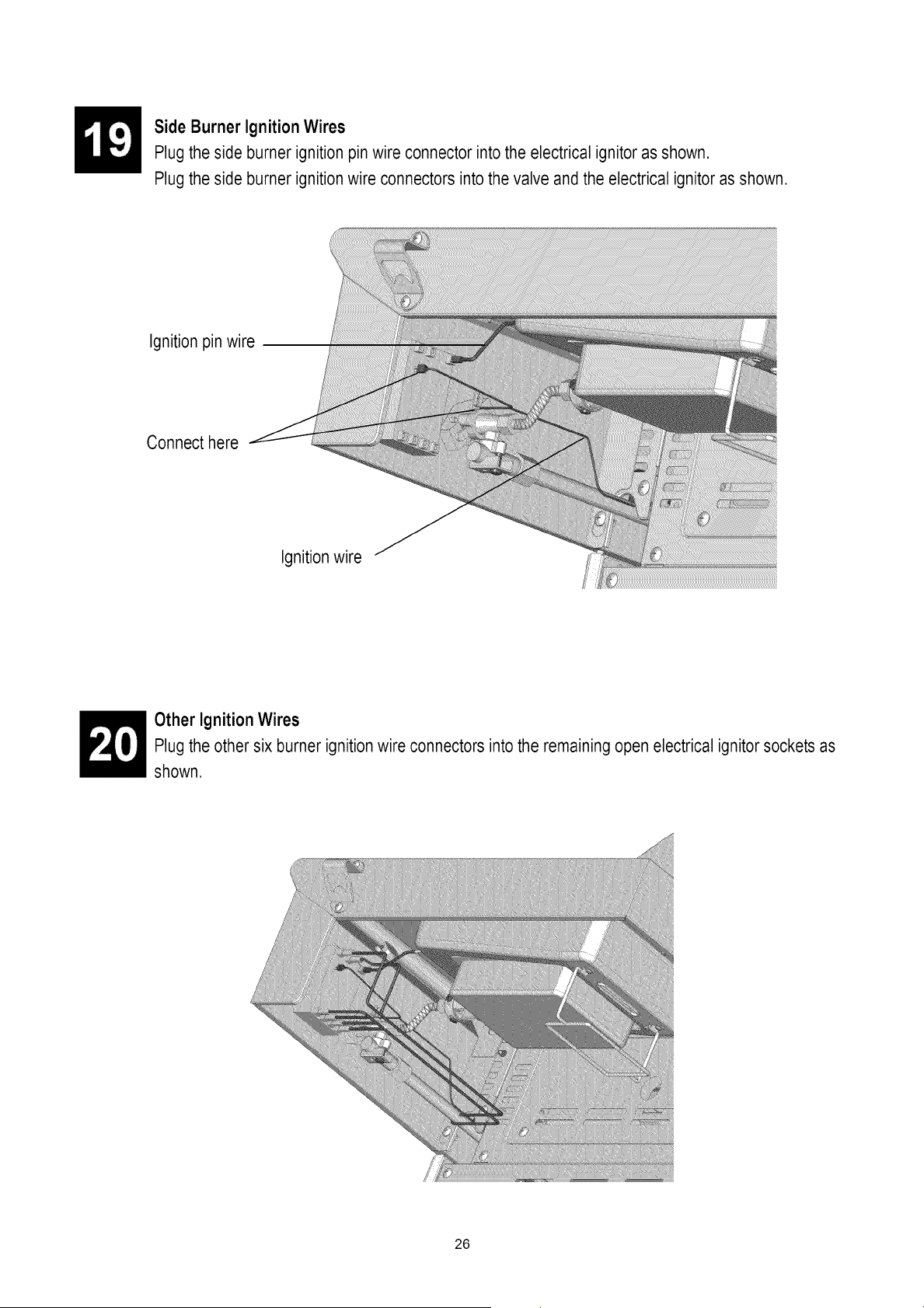
Side Burner Ignition Wires
Plug the side burner ignition pin wire connector into the electrical ignitor as shown.
Plug the side burner ignition wire connectors into the valve and the electrical ignitor as shown.
Ignition pin wire
Connect here
Ignitionwire
Other Ignition Wires
Plug the other six burner ignition wire connectors into the remaining open electrical ignitor sockets as
shown.
26
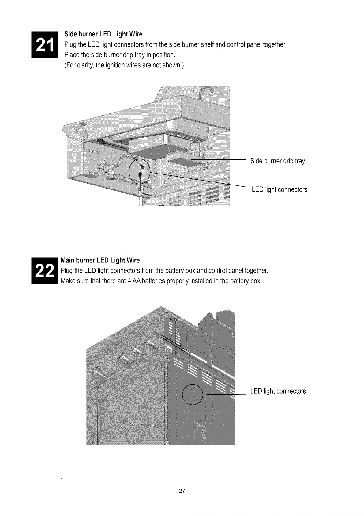
Side burner LED Light Wire
Plug the LED light connectors from the side burner shelf and control panel together.
Place the side burner drip tray in position.
(For clarity,the ignition wires are not shown.)
Side burner drip tray
LED light connectors
Main burner LED Light Wire
Plug the LED light connectors from the battery box and control panel together.
Make sure that there are 4 AA batteries properly installed in the battery box.
LED light connectors
27
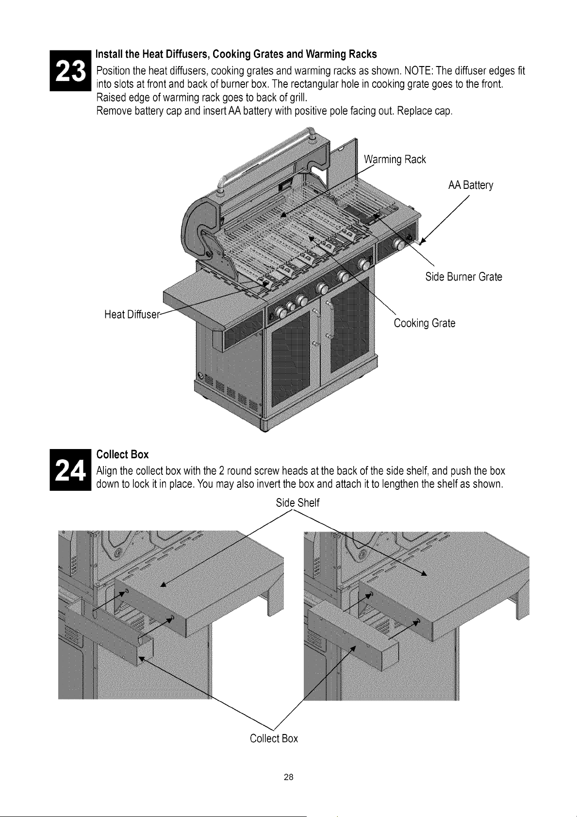
Install the Heat Diffusers, Cooking Grates and Warming Racks
Position the heat diffusers, cooking grates and warming racks as shown. NOTE: The diffuser edges fit
into slots at front and back of burner box. The rectangular hole in cooking grate goes to the front.
Raised edge of warming rack goes to back of grill.
Remove battery cap and insertAA battery with positive pole facing out. Replace cap.
Heat
Warming Rack
AA Battery
Side Burner Grate
Cooking Grate
Collect Box
Align the collect box with the 2 round screw heads at the back of the side shelf, and push the box
down to lock it in place. You may also invert the box and attach it to lengthen the shelf as shown.
Side Shelf
Collect Box
28
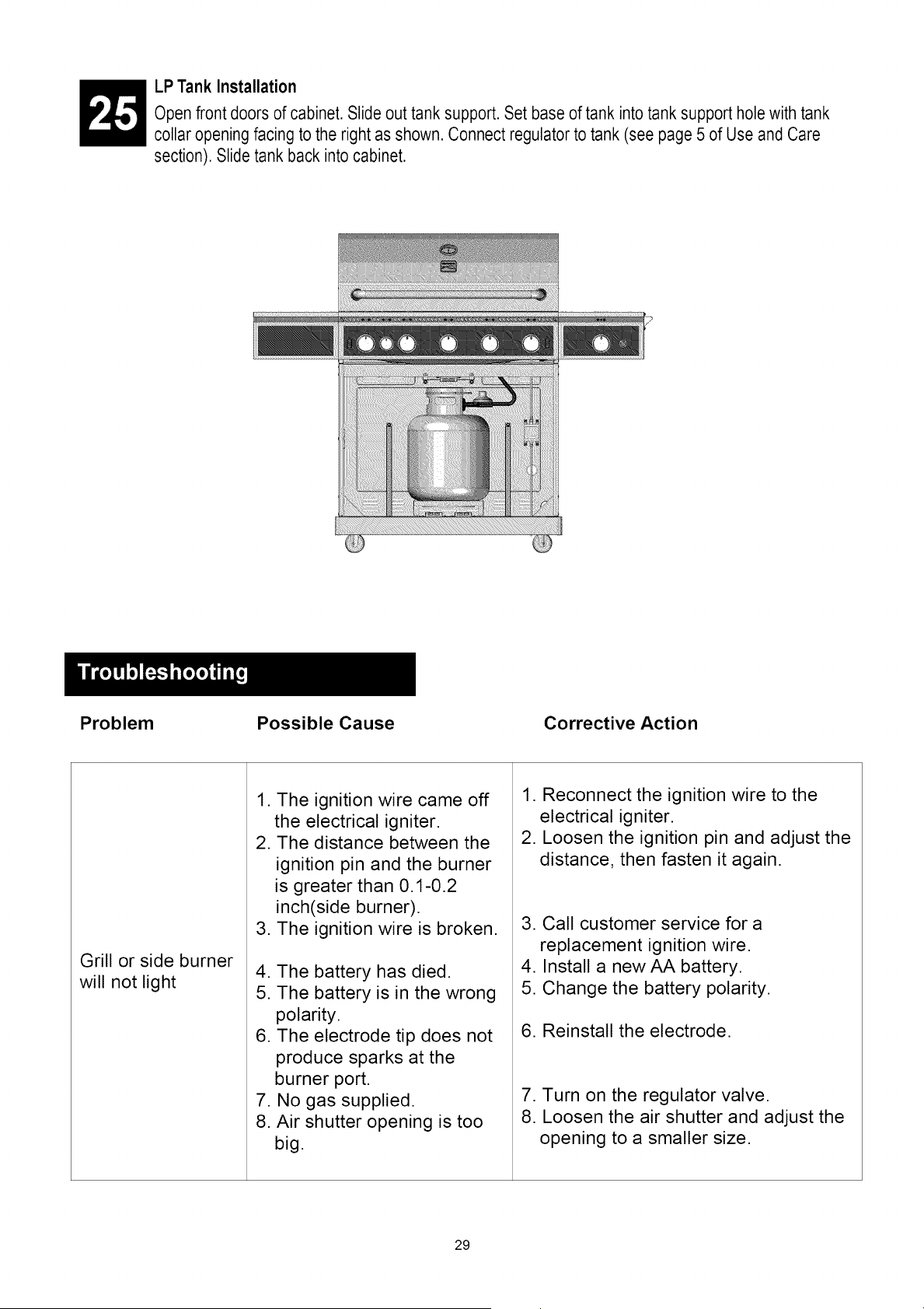
LP Tank Installation
Open front doors of cabinet. Slide out tank support. Set base of tank into tank support hole with tank
collar opening facing to the right as shown. Connect regulator to tank (see page 5 of Use and Care
section). Slide tank back into cabinet.
Problem Possible Cause Corrective Action
Grill or side burner
will not light
1. The ignition wire came off
the electrical igniter.
2. The distance between the
ignition pin and the burner
is greater than 0.1-0.2
inch(side burner).
3. The ignition wire is broken.
4. The battery has died.
5. The battery is in the wrong
polarity.
6. The electrode tip does not
produce sparks at the
burner port.
7. No gas supplied.
8. Air shutter opening is too
big.
1. Reconnect the ignition wire to the
electrical igniter.
2. Loosen the ignition pin and adjust the
distance, then fasten it again.
3. Call customer service for a
replacement ignition wire.
4. Install a new AA battery.
5. Change the battery polarity.
6. Reinstall the electrode.
7. Turn on the regulator valve.
8. Loosen the air shutter and adjust the
opening to a smaller size.
29

Problem Possible Cause Corrective Action
Burner flame is
yellow and gas
odor can be
smelled
Excessive flare-up
Burner blows out
Low heat with the
knob in "HI"
position
Low heat, natural
gas
1. The air shutter opening is
not properly set.
2. Spiders or insects block the
air shutter.
3. Gas leaks
1. Grilling fatty meats while
knobs on "HIGH".
2. Spray water on gas flames.
3. Hood closed when grilling.
1. LP tank is empty.
2. Burner is not aligned with
the control valve.
3. Gas supply is not sufficient.
1. Low heat is found in natural
gas models.
2. Ports are blocked.
3. LP tank has run out.
Gas pressure is significantly
affected by gas line and
length of gas line from house
gas line.
1. Loosen the air shutter and adjust the
opening to have blue flames.
1/4 in. opening for LPG.
1/8 in. or less opening for NG.
2. Clean blockages.
3. Check for the source of gas leaks.
1. Grill fatty meats when the grids are
cold while the knobs are on the "LOW"
setting. Move the meats to the
warming rack if flare up continues
until flame settles down.
2. Never spray water on gas flames.
3. Hood up when grilling.
1. Refill the LP Tank.
2. Install the burner correctly.
3. Check the gas supply hose and make
sure there are no leaks and no knots.
1. This model is set for 7 in. natural
gas usage. Please check your
natural gas supply system to
have correct gas pressure.
Regulator is not needed for NG
model.
Check the orifice if you installed
NG nozzles.
2. Clear ports of any obstructions.
3. Refill the LP tank.
Check your gas line and make
corrections by following the chart
below.
From House to Grill
Distance Tubing Size
Up to 25 ft. 3/8 in. diameter
26 -50 ft. 1/2 in. diameter
2/3 in. of run 3/4 in.
51 -100 ft. 1/3 in. of run 1/2 in.
30
Problem Possible Cause Corrective Action
Low heat,
LP gas
Sudden drop in
gas flow or low
flame
Cooking light will
not turn on.
LED control panel
lights do not light
up.
The propane regulator
assembly incorporates an
excess flow device designed
to supply the grill with
sufficient gas flow. Rapid
changes in pressure can
trigger the excess flow device,
providing a low flame
and low temperature.
1. Out of gas. 1.
2. Excess flow valve tripped. 2.
3. Vapor lock at coupling 3.
nut/LP cylinder connection.
1. No power supply. 1.
2. Defective halogen bulb.
3. Internal wiring issue.
2.
3.
1. No power supply. 1.
2. Damaged wiring or loose
connection. 2.
3. Wiring not attached to
control panel switch.
4. Defective switch.
5. Defective LED's.
Please follow these instructions:
1. Make sure all burners are "OFF".
2. Open the tank valve and wait 5
minutes.
3. Light the burner one at a time
following the lighting instructions
listed on the door liner
,
,
5.
Check for gas in LP cylinder.
Turn off knobs, wait 30 seconds
and light grill. If flames are still
low, turn off knobs and LP
cylinder valve. Disconnect
regulator. Reconnect regulator
and leak test. Turn on LP cylinder
valve, wait 30 seconds and then
light grill.
Turn off knobs and LP cylinder
valve. Disconnect coupling nut
from cylinder. Reconnect and
retry.
Check power supply and make
sure transformer is properly
plugged in.
Replace the bulb.
Check the wiring connections
under the fire box. All wire
connections must be tight. If any
wires are damaged they should be
replaced.
Install AA batteries in the LED
battery box.
Check all wiring connections
between the battery box and the
LED light. Also check the
connections between the LED's on
the control panel.
Check the connection between the
LED light and the LED light switch.
Replace the switch.
Replace the LED lights.
31
Your Home
For troubleshooting, product manuals and expert advice:
managemylife
www.managemylife.com
For repair - in your home - of all major brand appliances,
lawn and garden equipment, or heating and cooling systems,
no matter who made it, no matter who sold it!
For the replacement parts, accessories and
owner's manuals that you need to do-it-yourself.
For Sears professional installation of home appliances
and items like garage door openers and water heaters.
1-800-4-MY-HOME ®
Call anytime, day or night (U.S.A. and Canada)
www.sears.com www.sears,ca
Our Home
For repair of carry-in items like vacuums, lawn equipment,
and electronics, call anytime for the location of your nearest
Sears PaNs & Repair Service Center
1-800-488-1222 (U.S.A.) 1-800-469-4663 (Canada)
www.sears.com www.sears,ca
To purchase a protection agreement on a product semiced by Sears:
1-800-827-6655 (U.S.A.) 1-800-361-6665 (Canada)
Para pedir servicio de reparaci6n
a domicilio, y para ordenar piezas:
1-888-SU-HOGAR ®
(t-888-784-6427)
www,sears.com
Au Canada pour service en fran£ais:
1-800-LE-FOYER Mc
(1-800-533-6937)
w^ww,sea rs_ca
® Registered Trademark / _M Trademark of KCD IP, LLC in the United States, or Sears Brands, LLC in other countries
® Marca Registrada ! TM Marca de F_brica de KCD IP, LLC en Estados Unidos, o Sears Brands, LLC in otros paises
_c Marque de commerce ! Mo Marque depos6e de Sears Brands, LLC
32