TECHNICAL EDUCATION
JOB AID 4317326A
KAR-11
2001 K MODEL
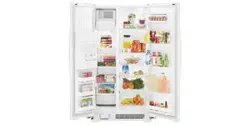
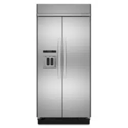
BUILT-IN SIDE-BY-SIDE
REFRIGERATOR WITH VARIABLE
CAPACITY COMPRESSOR
MODELS:
KSSC36FKB00
KSSC36FKS00
KSSC36QKS00
KSSC42FKB00
KSSC42FKS00
KSSC42QKS00
KSSC48FKB00
KSSC48FKS00
KSSC48QKS00
KSSP36QKS00
KSSP42QKS00
KSSP48QKS00
KSSS36FKB00
KSSS36FKT00
KSSS36FKW00
KSSS36FKX00
KSSS36QKB00
KSSS36QKT00
KSSS36QKW00
KSSS36QKX00
KSSS42FKB00
KSSS42FKT00
KSSS42FKW00
KSSS42FKX00
KSSS42QKB00
KSSS42QKT00
KSSS42QKW00
KSSS42QKX00
KSSS48FKB00
KSSS48FKT00
KSSS48FKW00
KSSS48FKX00
KSSS48QKB00
KSSS48QKT00
KSSS48QKW00
KSSS48QKX00
Downloaded from www.ManualsFile.com manuals search engine

- ii -
WHIRLPOOL CORPORATION assumes no responsibility for any repairs made
on our products by anyone other than Authorized Service Technicians.
FORWARD
This KitchenAid Job Aid, 2001 K Model Built-In Side-By-Side Refrigerator With Variable Capacity
Compressor (Part No. 4317326A), provides the technician with information on the installation and
service of the Built-In Side-By-Side Refrigerator. It is to be used as a training Job Aid and Service
Manual. For specific information on the model being serviced, refer to the “Use and Care Guide,”
or “Tech Sheet” provided with the refrigerator.
The Wiring Diagrams and Strip Circuits used in this Job Aid are typical and should be used for
training purposes only. Always use the Wiring Diagram supplied with the product when servicing
the unit.
GOALS AND OBJECTIVES
The goal of this Job Aid is to provide detailed information that will enable the service technician to
properly diagnose malfunctions and repair the Built-In Side-By-Side Refrigerator.
The objectives of this Job Aid are to:
• Understand and follow proper safety precautions.
• Successfully troubleshoot and diagnose malfunctions.
• Successfully perform necessary repairs.
• Successfully return the refrigerator to its proper operational status.
Copyright © 2002, Whirlpool Corporation, Benton Harbor, MI 49022
Downloaded from www.ManualsFile.com manuals search engine
- iii -
TABLE OF CONTENTS
Page
GENERAL............................................................................................................................... 1-1
Safety First......................................................................................................................... 1-1
Electrical Power Supply & Grounding Requirements ................................................... 1-1
Anti-Tip Requirements.................................................................................................. 1-2
Electrostatic Discharge (ESD) Sensitive Electronics.................................................... 1-2
Model & Serial Number Designations ................................................................................ 1-3
Model & Serial Number Label And Tech Sheet Locations................................................. 1-4
Specifications..................................................................................................................... 1-5
Refrigerator Warranty ........................................................................................................ 1-8
INSTALLATION INFORMATION ........................................................................................... 2-1
THEORY OF OPERATION ..................................................................................................... 3-1
COMPONENT ACCESS ......................................................................................................... 4-1
Component Locations ........................................................................................................ 4-1
Removing The Unit Compartment Cover........................................................................... 4-2
Removing A Door Switch, The Power Switch, The Inverter Assembly,
And The Main Control Board Assembly.......................................................................... 4-4
Removing The Condenser Fan Motor ............................................................................... 4-8
Removing The Compressor And Filter/Drier...................................................................... 4-9
Removing The Bimetal, The Evaporator Fan Motor,
The Defrost Heater, And The Evaporator ..................................................................... 4-10
Removing The Touch/Display Board & The Motorized Air Door ..................................... 4-14
Removing The Ice Maker And The Auger Motor & Crush/Cube Solenoid....................... 4-16
Removing A Thermistor ................................................................................................... 4-18
Removing A Light Socket ................................................................................................ 4-19
Removing The Water Reservoir ...................................................................................... 4-20
Removing The Water Valve ............................................................................................. 4-22
Removing The Water & Ice Dispenser ............................................................................ 4-23
Removing A Door Gasket ................................................................................................ 4-25
Removing The Freezer Or Refrigerator Door .................................................................. 4-26
COMPONENT TESTING ........................................................................................................ 5-1
Thermistor.......................................................................................................................... 5-1
Evaporator Fan Motor ........................................................................................................ 5-2
Condenser Fan Motor ........................................................................................................ 5-2
Compressor & Inverter....................................................................................................... 5-3
Motorized Air Door ............................................................................................................. 5-4
Defrost Heater & Bimetal ................................................................................................... 5-4
Main Control Board ............................................................................................................ 5-5
Crush/Cube Solenoid......................................................................................................... 5-6
Ice Maker Auger Motor ...................................................................................................... 5-6
Water Valve Solenoid ........................................................................................................ 5-7
Door Switch ....................................................................................................................... 5-7
Downloaded from www.ManualsFile.com manuals search engine
- iv -
DIAGNOSIS & TROUBLESHOOTING ................................................................................... 6-1
Diagnosis ........................................................................................................................... 6-1
Pre-Diagnostics Checks ................................................................................................. 6-1
Diagnostics Mode ........................................................................................................... 6-1
Water Filter Input (WFI) Test .......................................................................................... 6-2
Troubleshooting Chart ....................................................................................................... 6-3
WIRING DIAGRAMS & STRIP CIRCUITS ............................................................................. 7-1
Wiring Diagram—Bottom Mount ........................................................................................ 7-1
Wiring Diagram—Side-By-Side Models ............................................................................. 7-2
Strip Circuits ...................................................................................................................... 7-3
Page
Downloaded from www.ManualsFile.com manuals search engine
1-1
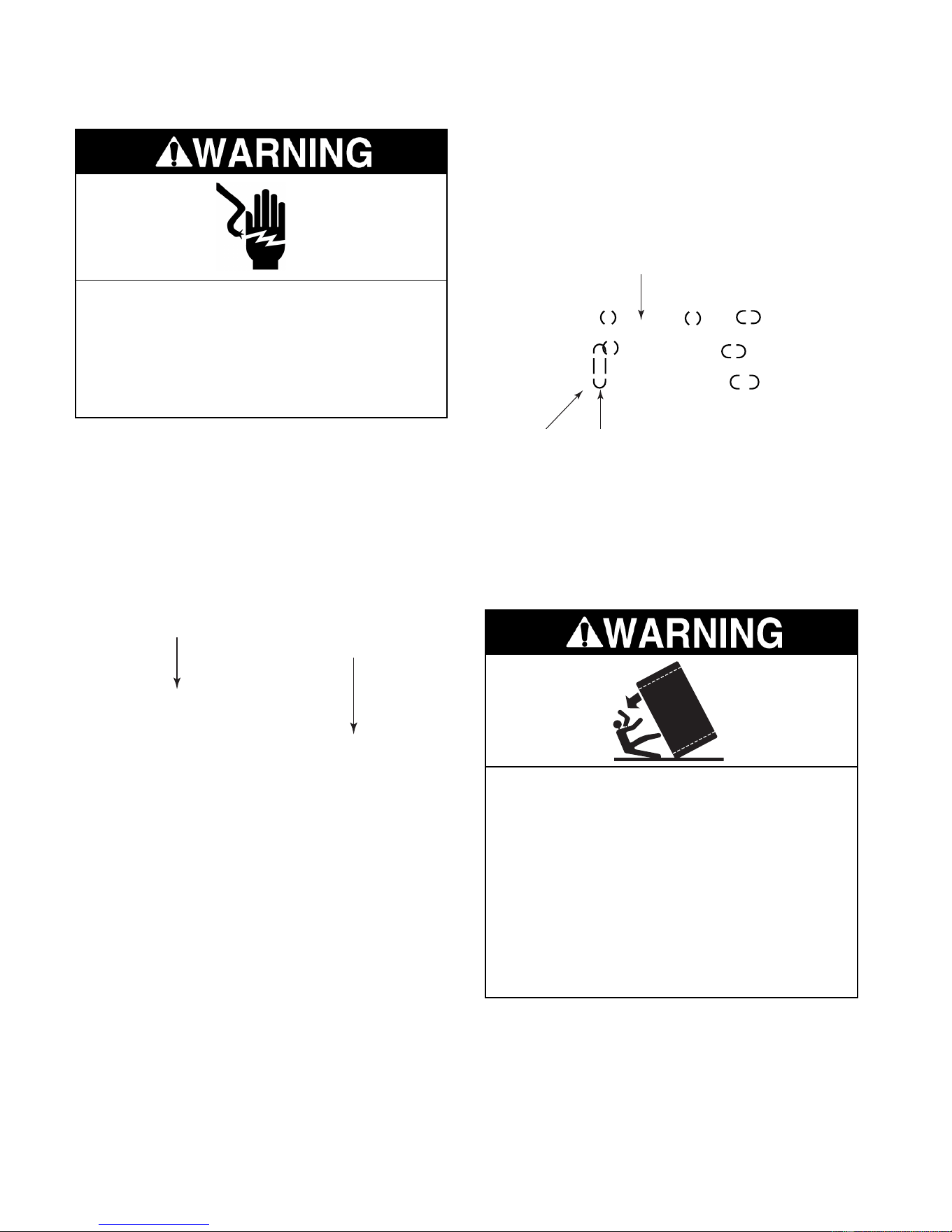
Electrical Shock Hazard
Plug into a grounded 3-prong outlet.
Do not remove ground prong.
Do not use an adapter.
Do not use an extension cord.
Failure to follow these instructions can
result in death, fire, or electrical shock.
Electrical Shock Hazard
Disconnect power before servicing.
Replace all panels before operating.
Failure to do so can result in death or
electrical shock.
GENERAL
SAFETY FIRST
Your safety and the safety of others is very important.
We have provided many important safety messages in this Job Aid and on the appliance. Always
read and obey all safety messages.
This is the safety alert symbol.
This symbol alerts you to hazards that can kill or hurt you and others.
All safety messages will follow the safety alert symbol and either the word
“DANGER” or “WARNING.” These words mean:
All safety messages will tell you what the potential hazard is, tell you how to reduce the chance
of injury, and tell you what can happen if the instructions are not followed.
You can be killed or seriously injured if you don’t
imme-
diately follow instructions.
You can be killed or seriously injured if you don’t follow
instructions.
ELECTRICAL POWER SUPPLY &
GROUNDING REQUIREMENTS
Downloaded from www.ManualsFile.com manuals search engine
1-2
ELECTROSTATIC DISCHARGE
(ESD) SENSITIVE ELECTRONICS
ESD problems are present everywhere. ESD
may damage or weaken the electronic control
assembly. The new control assembly may ap-
pear to work well after repair is finished, but
failure may occur at a later date due to ESD
stress.
• Use an antistatic wrist strap. Connect the
wrist strap to a green ground connection
point or unpainted metal in the appliance; or
touch your finger repeatedly to a green ground
connection point or unpainted metal in the
appliance.
• Before removing the part from its package,
touch the antistatic bag to a green ground
connection point or unpainted metal in the
appliance.
• Avoid touching electronic parts or terminal
contacts. Handle the electronic control as-
sembly by the edges only.
• When repackaging the failed electronic con-
trol assembly in an antistatic bag, observe
the above instructions.
Electrical Shock Hazard
Connect green ground wire to ground
screw.
Failure to do so can result in death or
electrical shock.
ANTI-TIP
REQUIREMENTS
Tip Over Hazard
Refrigerator is top heavy and tips easily
when not completely installed.
Keep doors taped closed until refrigera-
tor is completely installed.
Use two or more people to move and
install refrigerator.
Failure do so can result in death or
serious injury.
Downloaded from www.ManualsFile.com manuals search engine

1-3
MODEL & SERIAL NUMBER DESIGNATIONS
MODEL NUMBER
SERIAL NUMBER
MODEL NUMBER K S S S 4 2 Q K X 0 0
PRODUCT GROUP
K = KitchenAid Brand
PRODUCT IDENTIFICATION
BR = Bottom Mount Right Hand Hinge
BL = Bottom Mount Left Hand Hinge
SS = Side-By-Side Built-In
MERCHANDISING SCHEME/SERIES
C = Wrap Around Stainless Steel
P = Factory Installed Panel Kit
S = Framed Trim Kit (Panels Not Included)
CAPACITY/ SIZE
36 = 36″ Width
42 = 42″ Width
48 = 48″ Width
FEATURES
D = Ice & Water Dispensing
F = Factory Installed Ice Maker w/Filter
M = Factory Installed Ice Maker wo/Filter
Q = Ice/Crushed Ice & Water Dispensing w/Filter
YEAR OF INTRODUCTION
K = 2001
COLOR CODE
X = No Color Used
ENERGY POWER CONSUMPTION CHANGE
0 = Original, 1 = 1st Change, 2 = 2nd Change, Etc.
ENGINEERING CHANGE (NUMERIC)
0 = Original, 1 = 1st Change, 2 = 2nd Change, Etc.
SERIAL NUMBER Q L 3 0 10003
MANUFACTURING SITE
Q = LaVergne, TN
YEAR OF PRODUCTION
L = 2001
WEEK OF PRODUCTION
30th WEEK
PRODUCT SEQUENCE NUMBER
Downloaded from www.ManualsFile.com manuals search engine
1-5
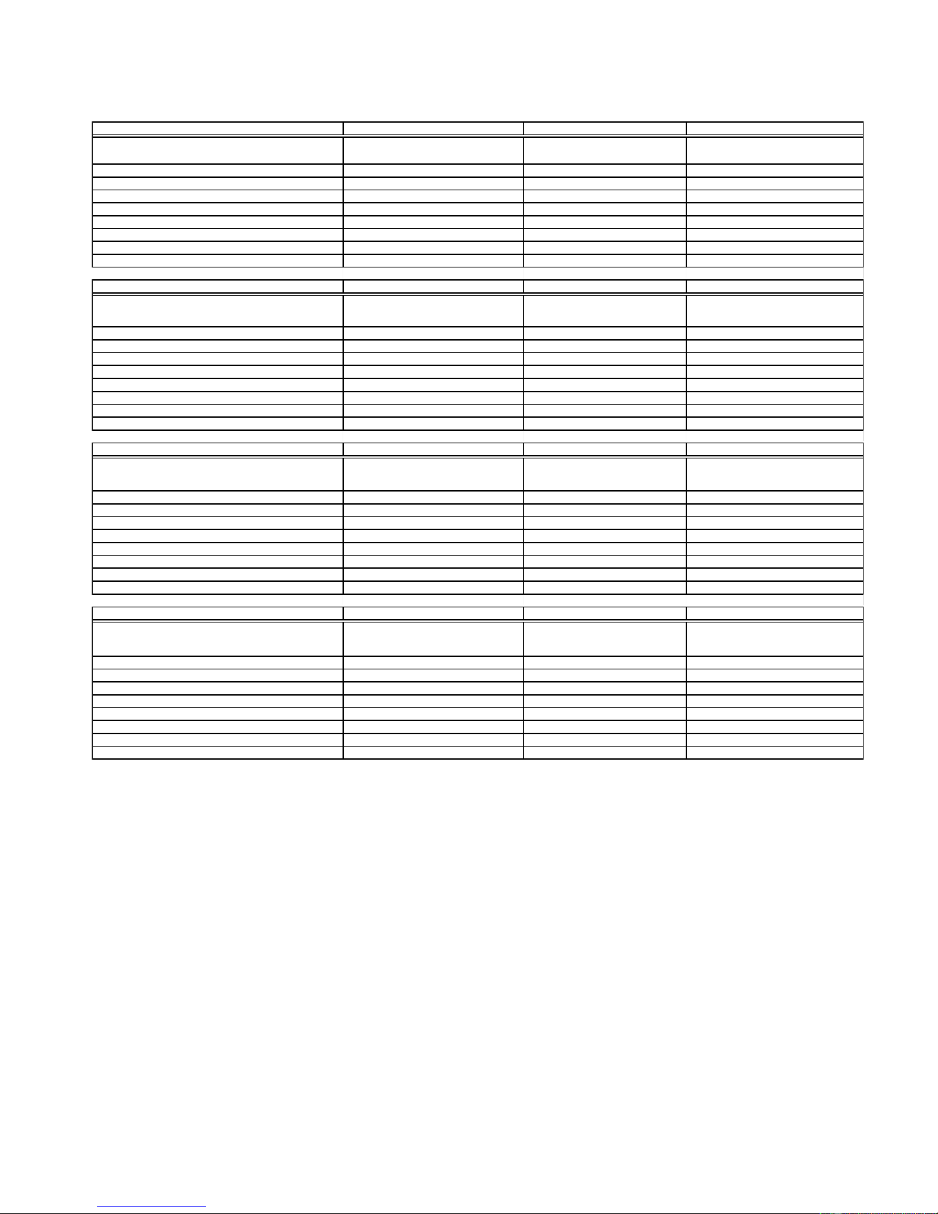
SPECIFICATIONS
Model Number KSSC36FKB KSSC36FKS KSSC36QKS
Model Description
Black Architect Series - Non-Disp.
with water filter
Architect Series - Non-Dispenser with
water filter
Stainless Steel Architect Series -
Disp. - with water filter
Size-Configuration 36" 36" 36"
Refrigerator Volume (Cu Ft) 13 13 13
Freezer Volume (Cu Ft) 7.5 7.5 7.4
Crated Weight (lbs) 500 500 500
Refrigerant 134a 134a 134a
Standard Warranty (Months) 24 24 24
Full Liner And Sealed System Warranty (Months) 72 72 72
Sealed System Warranty (Months) 144 144 144
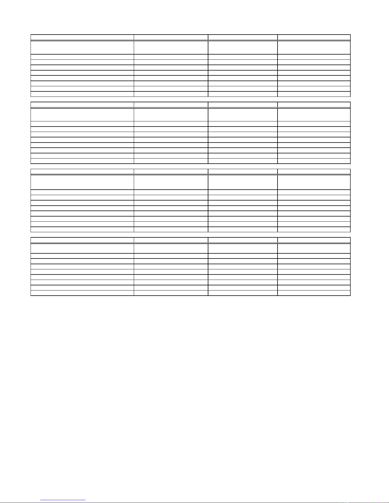
Model Number KSSC42FKB KSSC42FKS KSSC42QKS
Model Description
Black Architect Series - Non-Dispenser
with water filter
Architect Series - Non-Dispenser
with water filter
Stainless Steel Architect -
Dispenser with water filter
Size-Configuration 42" 42" 42"
Refrigerator Volume (Cu Ft) 13 15.6 15.7
Freezer Volume (Cu Ft) 9.1 9.1 8.9
Crated Weight (lbs) 552 552 552
Refrigerant 134a 134a 134a
Standard Warranty (Months) 24 24 24
Full Liner And Sealed System Warranty (Months) 72 72 72
Sealed System Warranty (Months) 144 144 144
Model Number KSSC48FKB KSSC48FKS KSSC48QKS
Model Description
Black Architect Series - Non-Dispenser
with water filter
Architect Series - Non-Dispenser with
water filter
Stainless Steel Architect Series
with Dispenser with Water Filter
Size-Configuration 48" 48" 48"
Refrigerator Volume (Cu Ft) 18.3 18.3 18.4
Freezer Volume (Cu Ft) 10.7 10.7 10.5
Crated Weight (lbs) 579 579 579
Refrigerant 134a 134a 134a
Standard Warranty (Months) 24 24 24
Full Liner And Sealed System Warranty (Months) 72 72 72
Sealed System Warranty (Months) 144 144 144
Model Number KSSP36QKS KSSP42QKS KSSP48QKS
Model Description
Stainless Steel - Dispenser - Factory
Installed Panels with water filter
Stainless Steel - Dispenser - Factory
Installed Panels with water filter
Stainless Steel - Dispenser - Factory
Installed Panels with Water Filter
Size-Configuration 36" 42" 48"
Refrigerator Volume (Cu Ft) 13 15.7 18.4
Freezer Volume (Cu Ft) 7.4 8.9 10.5
Crated Weight (lbs) 500 552 579
Refrigerant 134a 134a 134a
Standard Warranty (Months) 24 24 24
Full Liner And Sealed System Warranty (Months) 72 72 72
Sealed System Warranty (Months) 144 144 144
Downloaded from www.ManualsFile.com manuals search engine
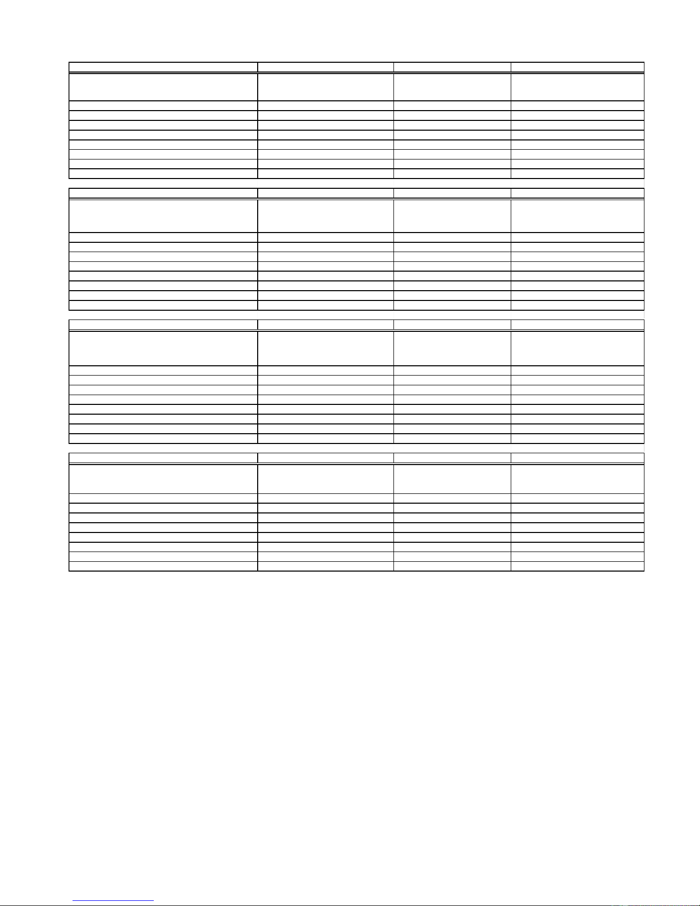
1-6
Model Number KSSS36FKB KSSS36FKT KSSS36FKW
Model Description
Black Trim -Custom Panels Required-
Non-Dispenser with water filter
Biscuit Trim -Custom Panels Required-
Non-Dispenser with water filter
White Trim-Non-Dispenser-Custom
Panels Required with water filter
Size-Configuration 36" 36" 36"
Refrigerator Volume (Cu Ft) 13 13 13
Freezer Volume (Cu Ft) 7.5 7.5 7.5
Crated Weight (lbs) 500 500 500
Refrigerant 134a 134a 134a
Standard Warranty (Months) 24 24 24
Full Liner And Sealed System Warranty (Months) 72 72 72
Sealed System Warranty (Months) 144 144 144
Model Number KSSS36FKX KSSS36QKB KSSS36QKT
Model Description
Brushed Aluminum Trim -Custom Panels
Required-Non-Dispenser with water filter
KitchenAid Black
Dispenser Water Filter
KitchenAid Biscuit
Dispenser Water Filter
Size-Configuration 36" 36" Side By Side 36" Side by Side
Refrigerator Volume (Cu Ft) 13 13 13
Freezer Volume (Cu Ft) 7.5 7.4 7.4
Crated Weight (lbs) 500 500 500
Refrigerant 134a 134a 134a
Standard Warranty (Months) 24 24 24
Full Liner And Sealed System Warranty (Months) 72 60 60
Sealed System Warranty (Months) 144 144 144
Model Number KSSS36QKW KSSS36QKX KSSS42FKB
Model Description
KitchenAid White Dispenser
with Water Filter
KitchenAid Black Dispenser
with Water Filter
Black Trim - Non-Dispenser with water
filter- Custom Panels Required
Size-Configuration 36" Side By Side 36" Side By Side 42"
Refrigerator Volume (Cu Ft) 13 13 15.6
Freezer Volume (Cu Ft) 7.4 7.4 9.1
Crated Weight (lbs) 500 500 552
Refrigerant 134a 134a 134a
Standard Warranty (Months) 24 24 24
Full Liner And Sealed System Warranty (Months) 60 60 72
Sealed System Warranty (Months) 144 144 144
Model Number KSSS42FKT KSSS42FKW KSSS42FKX
Model Description
Biscuit Trim - Non-Dispenser with water
filter- Custom Panels Required
White Trim - Non-Dispenser with water
filter- Custom Panels Required
Brushed Aluminum Trim - Non-Dispenser
with water filter- Custom Panels Required
Size-Configuration 42" 42" 42"
Refrigerator Volume (Cu Ft) 15.6 15.6 15.6
Freezer Volume (Cu Ft) 9.1 9.1 9.1
Crated Weight (lbs) 552 552 552
Refrigerant 134a 134a 134a
Standard Warranty (Months) 24 24 24
Full Liner And Sealed System Warranty (Months) 72 72 72
Sealed System Warranty (Months) 144 144 144
Downloaded from www.ManualsFile.com manuals search engine
1-7
Model Number KSSS42QKB KSSS42QKT KSSS42QKW
Model Description
KitchenAid Black Dispenser
Water with Filter
KitchenAid Biscuit
with Water Filter
KitchenAid White Water Filter
Size-Configuration 42" Side by Side 42" Side by Side 42" Side by Side
Refrigerator Volume (Cu Ft) 15.7 15.7 15.7
Freezer Volume (Cu Ft) 8.9 8.9 8.9
Crated Weight (lbs) 552 552 552
Refrigerant 134a 134a 134a
Standard Warranty (Months) 24 2 4 24
Full Liner And Sealed System Warranty (Months) 72 7 2 72
Sealed System Warranty (Months) 144 144 144
Model Number KSSS42QKX KSSS48FKB KSSS48FKT
Model Description
Black Dispenser-Brushed Aluminum
Trim-Custom Panels Required
Black Trim Model-Custom
Panels Required-Non-Dispenser
with water filter
Biscuit Trim Model-Custom Panels
Required-Non-Dispenser with water filter
Size-Configuration 42" 48" 48"
Refrigerator Volume (Cu Ft) 15.7 18.3 18.3
Freezer Volume (Cu Ft) 8.9 10.7 10.7
Crated Weight (lbs) 552 579 579
Refrigerant 134a 134a 134a
Standard Warranty (Months) 24 2 4 24
Full Liner And Sealed System Warranty (Months) 72 7 2 72
Sealed System Warranty (Months) 144 144 144
Model Number KSSS48FKW KSSS48FKX KSSS48QKB
Model Description
White Trim Model-Custom Panels Required-
Non-Dispenser with water filter
Brushed Aluminum Trim Model-
Custom Panels Required-Non-
Dispenser with water filter
KitchenAid Black Dispenser
Water with Filter
Size-Configuration 48" 48" 48" Side by Side
Refrigerator Volume (Cu Ft) 18.3 18.3 18.4
Freezer Volume (Cu Ft) 10.7 10.7 10.5
Crated Weight (lbs) 579 579 579
Refrigerant 134a 134a 134a
Standard Warranty (Months) 24 2 4 24
Full Liner And Sealed System Warranty (Months) 72 7 2 72
Sealed System Warranty (Months) 144 144 144
Model Number KSSS48QKT KSSS48QKW KSSS48QKX
Model Description
KitchenAid Biscuit Dispenser
with Water Filter
KitchenAid White Dispenser
Water with Filter
KitchenAid Water Filter Black Dispenser-
Brushed Aluminum Trim-
Size-Configuration 48" Side by Side 48" Side by Side 48" Side by Side
Refrigerator Volume (Cu Ft) 18.4 18.4 18.4
Freezer Volume (Cu Ft) 10.5 10.5 10.5
Crated Weight (lbs) 579 579 579
Refrigerant 134a 134a 134a
Standard Warranty (Months) 24 2 4 24
Full Liner And Sealed System Warranty (Months) 72 7 2 72
Sealed System Warranty (Months) 144 144 144
Downloaded from www.ManualsFile.com manuals search engine

1-8
KITCHENAID
®
BUILT-IN REFRIGERATOR WARRANTY
TWO-YEAR FULL WARRANTY ON REFRIGERATOR
For two years from the date of installation, when this refrigerator (excluding the water filter cartridges) is operated
and maintained according to instructions attached to or furnished with the product, KitchenAid will pay for factory
specified replacement parts and repair labor costs to correct defects in materials or workmanship. Replacement parts
and labor costs to correct defects in light bulbs, one year. Service must be provided by a KitchenAid designated
service company.
Water filter cartridge: 30 day limited warranty on water filter. For 30 days from the date of purchase, when this filter
is operated and maintained according to instructions attached to or furnished with the product, KitchenAid will pay
for replacement parts to correct defects in materials and workmanship.
THIRD THROUGH SIXTH YEAR LIMITED WARRANTY
In third through sixth years from the date of installation, when this refrigerator is operated and maintained according
to instructions attached to or furnished with the product, KitchenAid will pay for factory specified replacement parts
and repair labor costs to correct defects in materials or workmanship in the sealed refrigeration system. These parts
are: compressor, evaporator, condenser, dryer, and connecting tubing. Service must be performed by a KitchenAid
designated service company.
SEVENTH THROUGH TWELFTH YEAR LIMITED WARRANTY
In seventh through twelfth years from date of installation, when this refrigerator is operated and maintained according
to instructions attached to or furnished with the product, KitchenAid will pay for factory specified replacement parts
to correct defects in materials or workmanship in the sealed refrigeration system. These parts are: compressor,
evaporator, condenser, dryer, and connecting tubing.
LIMITED LIFETIME WARRANTY
For the life of the product, when this refrigerator is operated and maintained according to instructions attached to or
furnished with the product, KitchenAid will replace all Door Bins due to defective materials or workmanship.
KitchenAid will not pay for:
1. Service calls to correct the installation of the refrigerator, to instruct you how to use the refrigerator, to replace
house fuses or correct house wiring or plumbing, to replace light bulbs, or to replace water filters other than as
noted above.
2. Repairs when the refrigerator is used in other than normal, single-family household use.
3. Pickup and delivery. The refrigerator is designed to be repaired in the home.
4. Damage resulting from accident, alteration, misuse, abuse, fire, flood, improper installation, acts of God, or use
of products not approved by KitchenAid or KitchenAid Canada.
5. Any food or medicine loss due to product failure.
6. Repairs to parts or systems resulting from unauthorized modifications made to the appliance.
7. Removal and replacement of trim or decorative panels that interfere with servicing the product.
8. Labor or parts installed by any non-designated service company during the full warranty period, unless approved
by KitchenAid before service is performed.
9. In Canada, travel or transportation expenses for customers who reside in remote areas.
10. Any labor costs during the limited warranty periods, except as stated above.
KITCHENAID AND KITCHENAID CANADA SHALL NOT BE LIABLE FOR INCIDENTAL OR CONSEQUEN-
TIAL DAMAGES.
Some states or provinces do not allow the exclusion or limitation of incidental or consequential damages, so this
exclusion or limitation may not apply to you. This warranty gives you specific legal rights, and you may also have
other rights which vary from state to state or province to province.
Outside the 50 United States and Canada, a different warranty may apply. Contact your authorized KitchenAid
dealer to determine if another warranty applies.
If you need service, first see the “Troubleshooting” section of the Use & Care Guide. After checking “Trouble-
shooting,” additional help can be found by checking the “Assistance or Service” section or by calling the
KitchenAid Customer Interaction Center, 1-800-422-1230 (toll-free), from anywhere in the U.S.A. In Canada,
contact your designated KitchenAid Canada Appliance service company or call: 1-800-807-6777.
Downloaded from www.ManualsFile.com manuals search engine
2-1
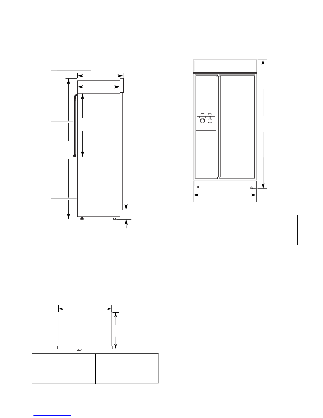
INSTALLATION INFORMATION
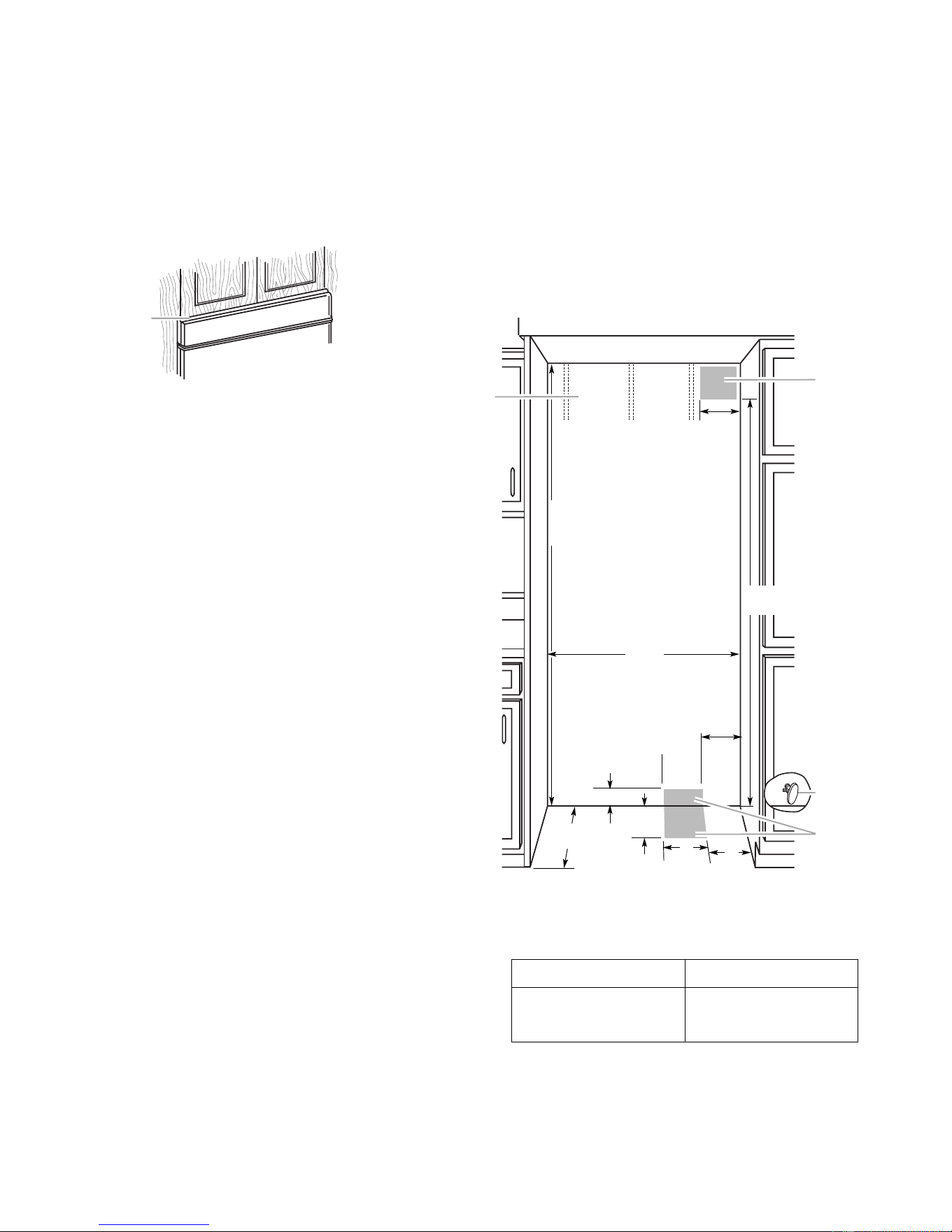
PRODUCT DIMENSIONS
Side View
25
1
/
8"
(64 cm)
3
2
1
23
1
/
2"
(60 cm)
24"
(61 cm)
83
1
/
8"
(211 cm)*
3
1
/
2" (9 cm)*
1. 25-1/8" (64 cm) dimension is to front of top grille
2. Power cord (24") (61 cm)
3. 5 ft. (1.5 m) water line tubing taped to back
NOTE: (*) Dimensions shown are for leg level-
ers extended 1/8″ (3 mm) below the rollers. For
levelers fully extended 1-1/4″ (32 mm) below
the rollers, add 1-1/8″ (29 mm) to this dimen-
sion.
Top View
Model Width A
36
"
(91 cm)
42
"
(106 cm)
48
"
(122 cm)
35
"
(89 cm)
41
"
(104 cm)
47
"
(119 cm)
25-1/8"
(64 cm)
A
Front View
83
1
/
8
"
(211 cm)
A
(see chart following)
Width of Refrigerator
36
"
(91 cm)
42
"
(106 cm)
48
"
(122 cm)
36-1/4
"
(92 cm)
42-1/4
"
(107 cm)
48-1/4
"
(123 cm)
Model Width A (as shown above)
NOTE: The width dimensions shown represent
the distance from outside trim to outside trim.
Downloaded from www.ManualsFile.com manuals search engine
2-2
1
1. A 1/2" (12.7 mm) space is require
d
Openings
The built-in refrigerator can be installed into a
recessed opening in the cabinets, or at the end
of cabinets using a side panel to enclose the
refrigerator side. The installation requires a
1/2″ (12.7 mm) clearance to remove the top
grille and for proper air flow.
Wall studs must be located on the rear wall 80″
to 90″ (203 - 229 cm) above the floor.
The solid soffit must be within 1″ (2.5 cm)
maximum above the refrigerator. If the solid
soffit is higher than 1″ (2.5 cm), or one is not
available, then the refrigerator must be braced
to prevent tipping during use. See “Anti-Tip
Boards” on page 2-3.
A grounded electrical outlet should be placed
in the top shaded area, 4″ (10.2 cm) from the
right side of the cabinets or end panel.
The water shutoff should be located in the base
cabinet on either side of the refrigerator. The
right side is recommended. The access hole
through the right cabinet must be within 1/2″
(12.7 mm) of the rear wall.
A 1/2″ (12.7 mm) hole for plumbing should be
within the bottom shaded area. The water line
can be through the floor or wall. If the recom-
mended water line location is used, no addi-
tional plumbing is necessary.
80" - 90"
(203-229 cm)
4"
(10.2 cm)
6"
(15.2 cm)
3" (7.6 cm)
83-1/4" (211.5 cm) min.
84-3/4" (215 cm) max.
to bottom of solid soffit.
(60 cm) min.
11"
(28 cm)
77"
(196 cm)
A
Width
(see chart following)
1
2
4
6"
(15.2 cm)
6"
(15.2 cm)
3
1. Stud location
2. Grounded electrical outlet location
3. Recommended water shutoff valve location
4. Plumbing hole and water line location (wall or floor)
36
"
(91.4 cm)
42
"
(106.7 cm)
48
"
(121.9 cm)
35-1/2
"
(90.2 cm)
41-1/2
"
(105.4 cm)
47-1/2
"
(120.7 cm)
Model Width A (as shown above)
Width of Opening:
23-1/2"
Downloaded from www.ManualsFile.com manuals search engine
2-3
WATER SUPPLY REQUIREMENTS
IMPORTANT:
• If you turn the refrigerator on before the
water line is connected, turn the ice maker
off.
• All installations must meet local plumbing
code requirements.
• Use copper tubing and check for leaks. In-
stall copper tubing only in areas where tem-
peratures will remain above freezing.
A kit is available with a 1/4″ (6.35 mm) saddle-
type shutoff valve, a union, and copper tubing.
Before purchasing the kit, make sure that a
saddle-type valve complies with local plumb-
ing codes. Do not use a piercing-type or a 3/16″
(4.76 mm) saddle valve because they reduce
water flow and clog easily.
Connect the ice maker to a cold water line with
water pressure between 15 and 100 psi (103 -
690 kPa). If you have questions about water
pressure, contact the water utility company.
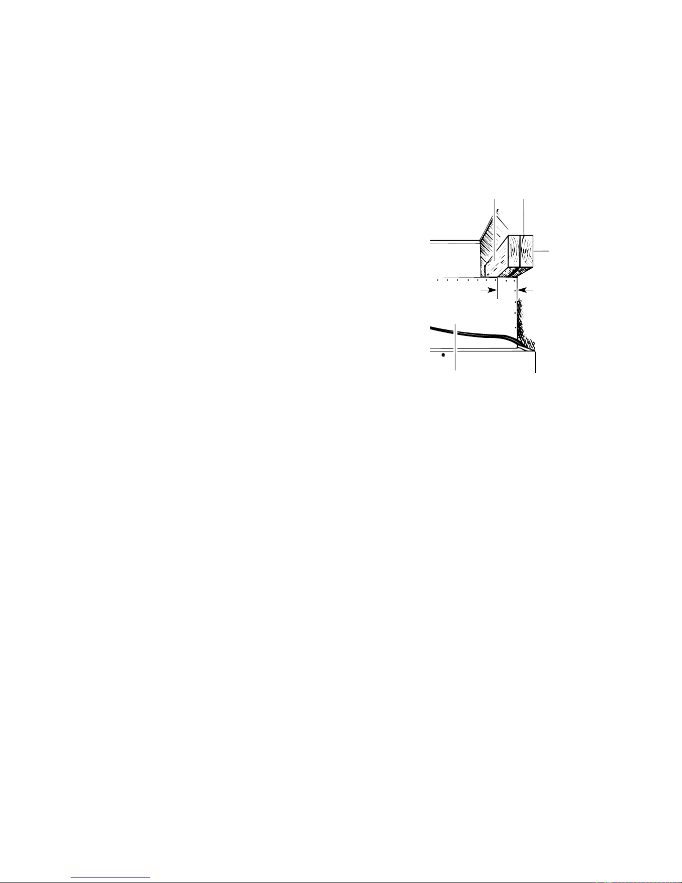
ANTI-TIP BOARDS
IMPORTANT:
• The solid soffit must be within 1″ (2.5 cm)
maximum above the refrigerator. If the solid
soffit is higher than 1″ (2.5 cm), or one is not
available, prevent the refrigerator from tip-
ping during use, as shown.
• It is recommended that the boards be in-
stalled before the refrigerator is installed.
• Boards must be long enough to fully cover
the width of the compressor cover.
21
3
2" (5 cm)
4
1. Center board 1/4" (6 mm) max. above refrigerato
r
2. Two 2" x 4" x 32" (5 cm x 10 cm x 81 cm) boards
3. Attach to studs with 6-#8 x 3" (7.6 cm) screws
4. Compressor cover
To Install The Anti-Tip Boards:
1. Mark the stud locations on the rear wall
80″ to 90″ (203 - 229 cm) above the floor.
2. Securely attach one or two 2″ x 4″ x 32″
(5 cm x 10 cm x 81 cm) wood boards to the
wall studs behind the refrigerator. Use six
#8 x 3″ (7.6 cm) or longer wood screws.
The wood screws must be screwed into
the studs at least 1-1/2″ (3.8 cm). The
boards must overlap the compressor cover.
• Locate the boards so the bottom surface of
the boards are 84″ (213 cm) from the floor.
• During installation, raise the refrigerator up
so there is 1/4″ (6.4 mm) maximum between
the top of the refrigerator and the bottom of
the anti-tip boards. Do not crush the con-
denser cover when raising the rear leveling
legs.
Downloaded from www.ManualsFile.com manuals search engine
2-4
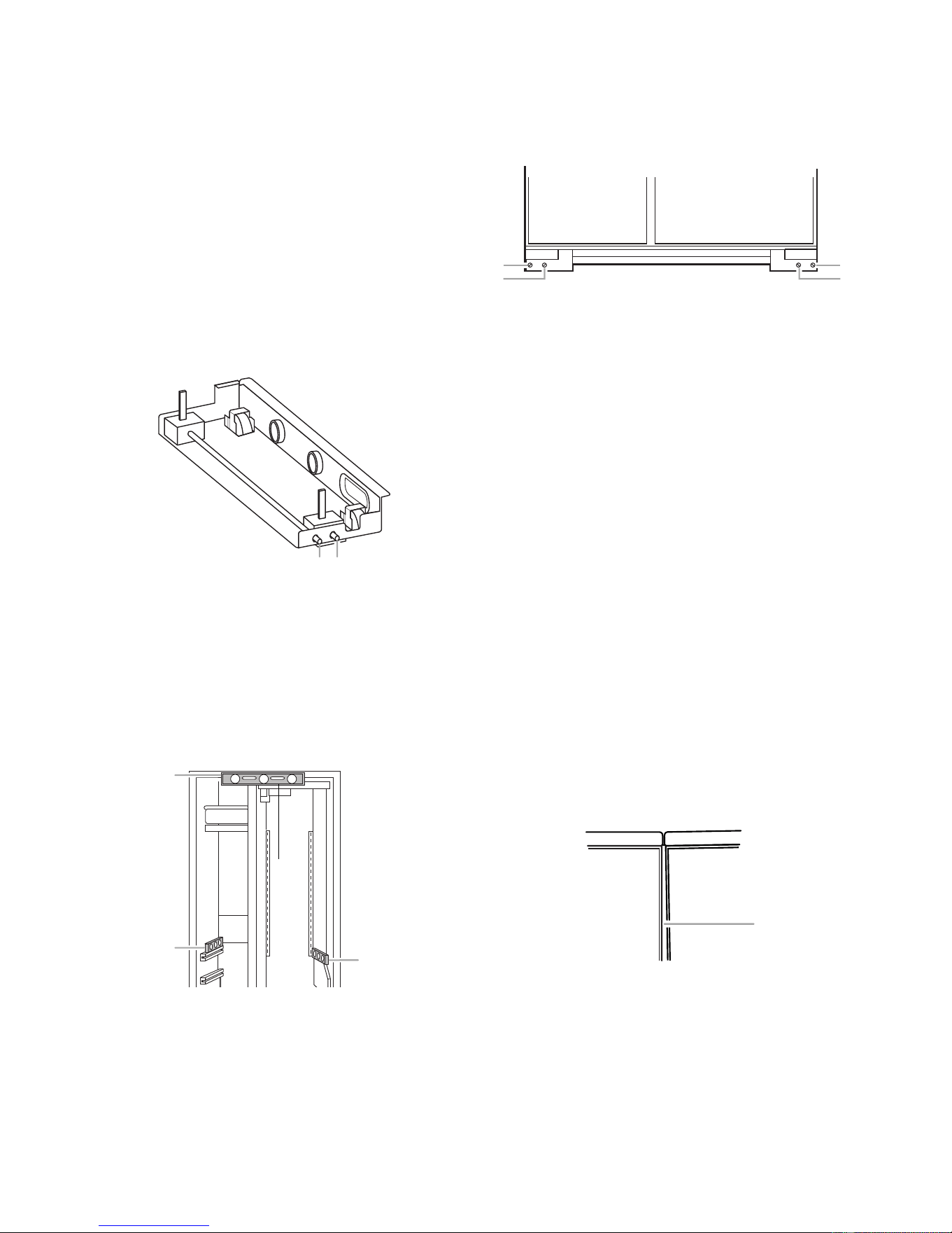
LOWERING THE LEVELING LEGS
All four leveling legs must contact the floor to
support and stabilize the full weight of the
refrigerator. Rollers are for moving the refrig-
erator, and not for permanent support.
Use a socket wrench to turn the leg levelers on
both sides of the refrigerator to the right (clock-
wise) until the refrigerator weight is supported
by the legs. The rollers should be off the floor.
To avoid cabinet damage, do not apply more
than 50 in/lbs (58 cm/kg) of torque to the
leveling legs.
1 2
1. Rear leveling legs
2. Front leveling legs
LEVELING THE REFRIGERATOR
NOTE: Door panels must be installed before
leveling.
1. Open the doors and place a level on top of
the refrigerator frame. Check to see if the
refrigerator is level from left to right.
2. Use the leveling bolts to adjust the leveling
legs until the refrigerator is level from left
to right.
3. Place a level on the shelves and check to
see if the refrigerator is level from front to
back.
4. Use the leveling bolts to adjust the leveling
legs until the refrigerator is level from front
to back.
5. Make sure that all four leveling legs con-
tact the floor and support the full weight of
the refrigerator.
6. Make a final check to see that the refrig-
erator is level.
ADJUSTING THE DOORS
Door Alignment
Use the following steps to adjust the door
alignment to the left, right, in, or out.
1. Inspect the spacing of the gap between
the freezer and refrigerator doors. Make
sure that the spacing between the doors is
the same distance at the top and bottom.
1
2
2
1. Level to check left to right leveling
2. Level to check front to back leveling
1
2
1
2
1. Rear leveling bolt
2. Front leveling bolt
1
1. Uneven door gap
2. If the door gap is uneven, the side trim
must be removed so that you can see the
entire door gasket liner. Remove the six
phillips screws holding the side trim.
Downloaded from www.ManualsFile.com manuals search engine
2-5
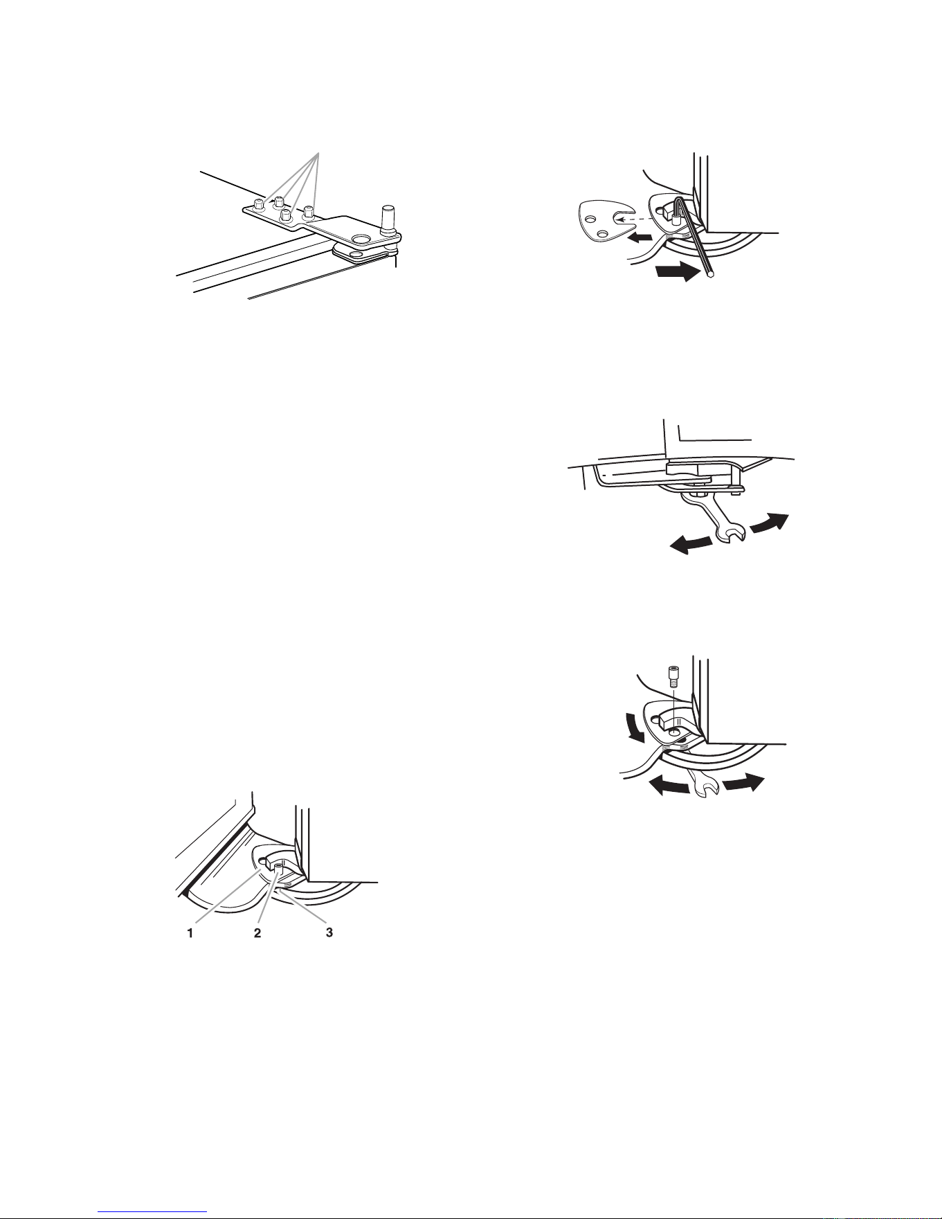
3. Loosen the four 3/8″ hex-head screws on
top of both door hinges.
1
1. Mounting screws
4. Adjust the hinges so that the door gap is
the same distance at the top and bottom.
5. Check the side door gasket gap. Make
sure that the distance is the same at the
top and bottom. Adjust the hinges, as
necessary.
6. Recheck the front door gap spacing to
make sure that it is properly aligned and
even.
7. Tighten the top hinge screws securely.
8. Reinstall the side door trim.
Door Height Adjustment
Use the following steps to adjust the door
height up or down after the doors have been
leveled.
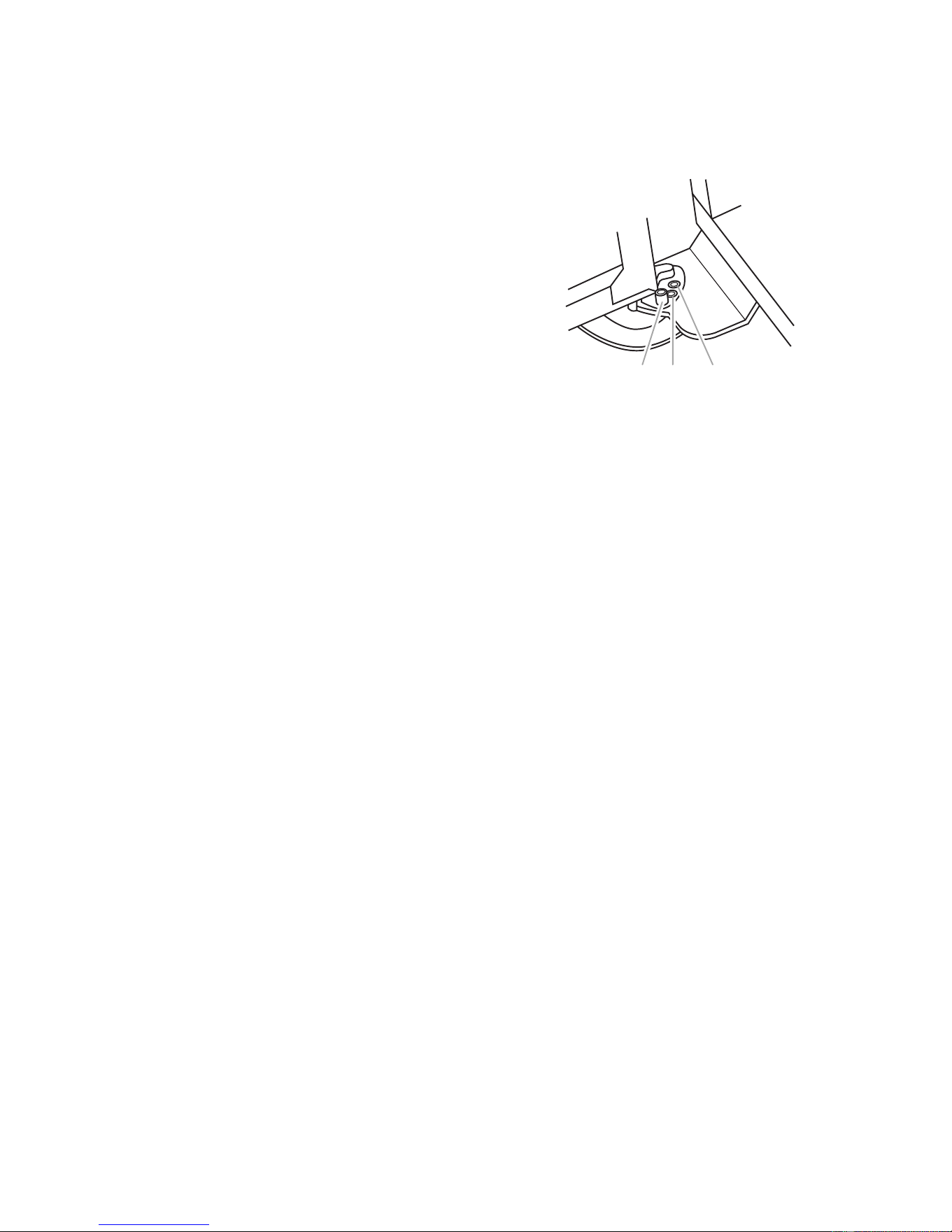
1. Open the freezer or refrigerator door and
locate the hinge assembly at the bottom of
the door.
1. Locking plate
2. Door stop screw
3. Bushing
2. Use an allen wrench and remove the door
stop screw and locking plate from the
bottom door hinge.
3. Use an open-end wrench and turn the
bushing, located under the bottom of the
hinge, to the left to raise the door, or to the
right to lower the door.
4. Replace the locking plate and door stop
screw. Turn the bushing slightly to align
the hinge and locking plate screw holes.
Downloaded from www.ManualsFile.com manuals search engine
2-6
Door Swing Adjustment
1. Open the refrigerator and freezer doors
and make sure that they open freely. If a
door opens too wide, remove the door
stop screw from the bottom hinge.
1. Door stoop setscrew (130
°
position)
2. 110
°
position.
3. 90
°
position.
12 3
2. Move the door to the desired open posi-
tion, and then reinstall the door stop screw
at one of the three holes that is closest to
the desired position.
Downloaded from www.ManualsFile.com manuals search engine
3-1
THEORY OF OPERATION
OVERVIEW
The KitchenAid Built-In Refrigerator Constant
Flow Temperature Management System uses
two thermistors to monitor temperature changes
inside the refrigerator and freezer compart-
ments. The electronic control manages the
operation of the variable capacity compressor
(VCC), a variable speed evaporator fan motor,
and a variable position air door. The air door
allows independent temperature control of the
refrigerator and freezer compartments.
The electronic control seeks the most efficient
means possible to maintain temperatures as it
controls the operation and speed of the com-
pressor and the evaporator fan motor. Higher
fan speed is used before increasing the com-
pressor speed to minimize power consump-
tion. A nearly constant run time is sought at the
lowest possible fan and compressor speed.
Freezer temperatures can be set from 9°F to
–9°F (–13°C to –23°C). Refrigerator tempera-
tures can be set from 46°F to 32°F, (8°C to
0°C).
The Adaptive Defrost Control (ADC) portion of
the electronic control utilizes “pulsed defrost”
technology to perform the defrost function (see
page 3-4).
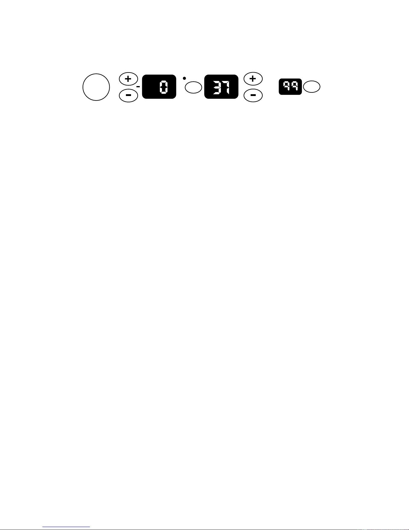
THE ELECTRONIC TEMPERATURE CONTROL PANEL
Power
On/Off
Warmer
Colder
Warmer
Colder
FREEZER REFRIGERATOR
WATER FILTER
PERCENT LEFT
RESET
°C
SELECT
The electronic control monitors the water valve
for total elapsed time and gallons of water
used. The number displayed on the Water
Filter Indicator (WFI) is the percentage of filter
usage remaining.
The numeric display can be set for Fahrenheit
or Celsius and displays the actual tempera-
tures. The display range for the refrigerator is
from 27°F to 70°F. The normal freezer display
range is from –9°F to 70°F. Temperatures
above or below these limits will be displayed at
the corresponding temperature limit. During
Max Cool, the freezer display will read –10°F,
and the refrigerator will read 32°F.
The display will show the temperature setting
any time the actual temperature is within ±6°F
of the customer setting. This will prevent con-
cern over temperature fluctuations when the
doors are opened. Press the temperature ad-
justment key to view the current temperature
setting, or to change the setting. When the
temperature adjustment key is used to change
the temperature setting, the display will brighten
for 5 seconds.
Available features include:
• Water Filter Indicator
• Max Cool
• Over-Temperature Alarm
• Holiday Mode
Downloaded from www.ManualsFile.com manuals search engine

3-2
Freezer Temperature Control —
Temperature Decreasing
When the freezer temperature begins to de-
crease, the process will reverse. The compres-
sor speed decreases, followed by the evapo-
rator fan speed.
Refrigerator Temperature Control —
Temperature Increasing
When the refrigerator calls for cooling while
the freezer is satisfied, the air door begins to
open, and the evaporator fan starts to run at
minimum speed. If the temperature continues
to rise, the air door will continue to open. If the
temperature continues to rise after the air door
is fully open, the evaporator fan speed will
gradually increase to a maximum of 3000 rpm.
If the temperature continues to rise, the com-
pressor starts to run, or if it has already been
running, begins to increase in speed.
Refrigerator Temperature Control —
Temperature Decreasing
As the refrigerator temperature approaches the
selected setting, the control compares the tem-
peratures in both compartments to determine
which compartment will control the fan speed.
If the freezer is further from the selected tem-
perature setting, it controls the fan speed, and
the air door begins to close, thus reducing the
airflow to the refrigerator.
If the freezer is satisfied, the air door remains
open, and the fan speed begins to decrease.
When the selected temperature setting is
reached, the air door closes.
TEMPERATURE CONTROL
The electronic control checks the resistance of
the thermistors, and compares it to both the
customer temperature settings and the last
thermistor reading taken. This information is
used to determine when to begin a cooling
operation, and if a change is necessary in the
damper setting, or the evaporator fan or com-
pressor speed.
When a warm refrigerator is first put into a
cooling mode, the air door partially opens, and
the compressor and evaporator fan motors
start to run at maximum rpm. The air door will
gradually move to its fully open position.
As the actual temperature in the refrigerator
nears the selected temperature setting, the
electronic control compares the temperatures
in both compartments. The compartment that
has the greatest need for cooling, will control
the speed of the evaporator fan motor.
Freezer Temperature Control —
Temperature Increasing
When the freezer calls for cooling, the com-
pressor begins to run at minimum rpm, (see the
chart on page 3-3), and the evaporator fan
begins to run at 2000 rpm. The compressor
and evaporator speeds are continuously up-
dated. Speed changes are made based on:
• The difference between the actual tempera-
ture and the selected temperature settings.
• The rate of temperature change.
If the temperature increases 4°F above the
selected temperature setting, the evaporator
fan speed begins to gradually increase. The
evaporator fan motor reaches the maximum
speed of 3000 rpm at 5°F above the selected
temperature setting, and the compressor speed
begins to gradually increase. A maximum com-
pressor speed of 4500 rpm will be reached at
9°F above the selected temperature setting.
Downloaded from www.ManualsFile.com manuals search engine
3-3
COMPRESSOR
The main control board supplies a 5 vdc, peak-
to-peak square wave, at 54 to 150 Hz, to the
inverter board. A standard VOM will read ap-
proximately 2.5 vdc. The inverter board sup-
plies the variable capacity compressor with
three-phase 230 vac. Varying the frequency
to the inverter board, and not the voltage,
changes the speed of the compressor. The
compressor can run at speeds of 1620 to 4500
rpm.
NOTE: It is not necessary, nor is it recom-
mended, to test the output of the inverter board.
While the compressor is running, its speed is
continuously updated. Speed is determined
after analyzing two factors:
• The difference between the actual tempera-
ture and the selected temperature settings.
• The rate of temperature change.
Minimum compressor speed is based on the
freezer’s selected temperature setting, as
shown in the following chart.
The compressor generally cycles on and off
according to the cut-in and cut-out tempera-
tures of the freezer, however, the refrigerator
can turn on the compressor if the evaporator
fan is at maximum speed and the refrigerator
temperatures are not dropping.
COMPRESSOR PROTECTION
To protect the compressor and maintain effi-
ciency, minimum compressor off time is pro-
grammed into the control. When the compres-
sor turns off, a minimum of 7 minutes must
elapse before allowing a restart.
The inverter board utilizes a current limiting
device and thermal protection that eliminates
the need for a compressor mounted thermal
protector.
EVAPORATOR FAN MOTOR
The evaporator fan motor is a 12 vdc, variable
speed motor. The motor has four wires:
• A blue wire provides feedback to monitor the
speed of the motor.
• A red wire provides a constant 12 vdc.
• A yellow wire provides a variable voltage of
between 5 vdc and 17 vdc to control the
motor speed from 2000 to 3000 rpm.
• A white wire provides a common return.
EVAPORATOR FAN &
AIR DOOR DELAY
After defrost, an evaporator fan delay prevents
unnecessary movement of warm, moist air
through the refrigerator, by chilling the evapo-
rator prior to starting the fan. Immediately af-
ter defrost drip time, the compressor starts at
4500 rpm, but the evaporator fan is delayed
for 8 minutes. The air door remains closed for
8 minutes following defrost.
AIR DOOR
The air door is driven by a reversible DC
stepper motor. The motor operates on a 12
vdc, peak-to-peak square wave. Voltage is
delivered to the air door in a series of short
pulses. It is not possible to obtain a reliable
voltage reading with a VOM.
Separate windings are used to move the air
door open or closed. The door can be in any
one of 1800 positions from 0 to 90 degrees.
The air door is used to fine-tune the airflow to
the refrigerator.
Freezer Temperature Compressor
Setting (°°
°°
F)
Minimum Speed
9 to –2 1620 rpm
–3 1800 rpm
– 4 2000 rpm
–5 2200 rpm
–6 2400 rpm
–7 2600 rpm
–8 2800 rpm
–9 3000 rpm
–10 3200 rpm
Downloaded from www.ManualsFile.com manuals search engine

3-4
The refrigerator temperature determines the
opening of the air door. When the refrigerator
requires cooling, if the evaporator fan motor is
already running for the freezer, the air door
partially opens, and then adjusts, if necessary.
While the refrigerator is cooling, the door will
be adjusting continuously to maintain or re-
cover refrigerator temperature.
ADAPTIVE DEFROST
The adaptive defrost control allows the unit to
enter a defrost mode only when it is needed.
When powered up for the first time, the control
initiates a defrost cycle after 8 hours of com-
pressor run time. By monitoring the duration of
defrost heating time and compressor run time,
the control will continuously adapt the time
between defrosts to optimize efficiency. Time
between defrost periods will vary between 8
and 100+ hours.
Defrost will occur immediately when the com-
pressor has run at 4000 rpm or greater for 1
hour, and 8 hours have elapsed since the last
defrost.
PULSED DEFROST
For the first 2 minutes of defrost, the heater is
on continuously. It will then cycle off for 1
minute, and back on for 2 minutes. The heater
will continue to cycle at this ratio until the
bimetal opens, or until 33 minutes has elapsed.
At this point, heat is discontinued, and a
4-minute “drip time” begins. This allows the
water to drain before the unit returns to a
cooling mode. Maximum defrost time, (pulsed
heat on/off time + drip time) is 37 minutes.
When entering a defrost cycle, if the bimetal is
open, the time to defrost is reset to 8 hours, and
the control will time through the entire 37 minute
defrost period. During diagnostics this will al-
low a technician time to look for heater opera-
tion, and if necessary, bypass the bimetal.
POWER INTERRUPTION
After a power interruption, the following events
will occur:
• The unit returns to the same operating mode
and settings in use prior to the power inter-
ruption. If the unit was off, it remains off.
• Initially, the compressor, evaporator fan, and
condenser fan motors will be off.
• The air door will close, and then adjust to the
proper opening. The evaporator fan starts
when the air door opens.
• The adaptive defrost control resets the com-
pressor run time counter to 0, and if the
freezer is above 20°F, the time to defrost is
set to 8 hours.
• If the freezer temperature is below 12°F, the
compressor starts after a delay of 7 minutes.
If the freezer temperature is above 12°F, the
compressor starts immediately.
FAILURE DEFAULTS
In the event of a thermistor, or keypad failure,
the control uses one of the following default
modes, which will continue until the failure is
corrected.
Refrigerator Thermistor
If the control senses an open or a shorted
thermistor, the air door and the evaporator fan
motor will begin to operate on a timed on and
off cycle, based on current selected tempera-
ture settings. The evaporator fan motor will run
when the air door is open.
At mid-settings of 37°F / 0°F, the air door will
open for 16 minutes, and close for 30 minutes.
Setting the freezer colder, or the refrigerator
warmer, will reduce the door-open time. Set-
ting the freezer warmer, or the refrigerator
colder, will increase the door-open time.
Downloaded from www.ManualsFile.com manuals search engine

3-5
Freezer Thermistor
If the control senses an open or a shorted ther-
mistor, the compressor and the evaporator fan
motor will begin to operate on a timed on and
off cycle. The cycle time is based on current
selected temperature settings.
At mid-settings of 37°F / 0°C, the compressor
and the evaporator fan motors will run for 35
minutes, and be off for 25 minutes. Setting the
freezer colder will increase the run time. Set-
ting the freezer warmer will decrease the run
time.
The compressor will run at minimum speed.
The evaporator fan will also run at minimum
speed, unless the refrigerator compartment
requests a higher speed.
Keypad
If the control detects that the keypad is not
working, it reverts to the default temperature
settings of 37°F in the refrigerator, and 0°F in
the freezer.
Evaporator Fan Motor
If the evaporator fan motor malfunctions, the
compressor will run at 4500 rpm for an indefi-
nite period, except during the defrost periods.
The “Call Service Alarm” will sound until the
failure has been corrected.
ELECTRONIC CONTROL
THERMAL SHUTOFF
The electronic control utilizes an on-board ther-
mistor to shut the compressor off if the tem-
perature rises above 160°F (71°C). When the
temperature drops to 130°F (55°C), the com-
pressor returns to normal operation. This cycle
continues indefinitely until the cause of the high
temperature has been corrected.
If this cycle is repeated four times within 24
hours, the “Call Service” indicator lights, and
the alarm sounds.
MAX COOL MODE
Max Cool changes the refrigerator tempera-
ture setting to 32°F (0°C) and the freezer to
–10°F (–23°C) for 24 hours. During Max Cool,
the freezer and refrigerator temperature dis-
plays show the new temperature settings, not
the actual temperatures.
In most cases the motors run 100% for more
than 1 hour. The control returns to the previous
user setting after 24 hours, or any time the
temperature settings are changed.
AUTOMATIC MAX ICE
Automatic Max Ice operates any time the ice
maker water valve is energized. The duration
of Automatic Max Ice is 1-1/2 hours. During
Automatic Max Ice the following occurs:
• The freezer display shows the user tempera-
ture settings and not the actual temperature.
• The freezer temperature setting changes to
–9°F (–23°C).
• The evaporator fan runs at 3000 rpm.
• The compressor runs the entire 1-1/2 hour
mode. Speed is determined by the differ-
ence between actual freezer temperature
and -9°F (-23°C).
HOLIDAY MODE
The Holiday Mode may be used for the follow-
ing occasions:
• On vacation.
• Religious observance (Sabbath Mode).
When the Holiday Mode is selected, the corre-
sponding green LED flashes for 2 seconds,
and then remains on, to indicate that the fea-
ture is activated.
Downloaded from www.ManualsFile.com manuals search engine

3-6
In the Holiday Mode the following occurs:
• Temperature selections remain at the cur-
rent setting, but are not displayed.
• The Water Filter Indicator is not displayed,
but monitoring continues.
• The audible signals are disabled.
• The ice maker is disabled.
• The interior lights are disabled.
• The temperature displays and all of the LEDs
will be off, except for the Holiday Mode LED.
The Holiday Mode LED will illuminate re-
gardless of the door position.
• Keypad operation is disabled, with the ex-
ception of the Holiday Mode key, or the
Power On/Off key.
The Holiday Mode will be cancelled if one of the
following occurs:
• Pressing the Power On/Off, or Holiday Mode
keypads.
• Failure of both thermistors.
• No feedback from the evaporator fan motor.
• Temperatures that are 15°F above user set-
tings in either compartment.
When the Holiday Mode is cancelled, the Holi-
day Mode LED turns off, and the control re-
verts to the settings in use prior to activation.
All inactive devices are restored, and the Wa-
ter Filter Indicator is updated.
The Adaptive Defrost Control function is not
effected by use of the Holiday Mode.
OVER-TEMPERATURE ALARM
The Over-Temperature Alarm sounds, and the
indicator light flashes when either the refrig-
erator temperature exceeds 48°F (9°C), or the
freezer temperature exceeds 15°F (–9°C) for
over 1-1/2 hours. The appropriate temperature
display flashes to show the user which com-
partment is effected. The alarm stops if the
temperature(s) returns to normal, but the red
Over-Temperature indicator and temperature
display will continue to flash. Pushing the Over-
Temperature Reset key turns off the Alarm and/
or indicator, and resets the Over-Temperature
Timer to zero.
CALL SERVICE ALARM
Call Service is a visual and audio signal that
alerts the user that the refrigerator needs ser-
vice. The Call Service Alarm will sound when:
• Both thermistors have failed.
• The evaporator fan motor loses its feedback
signal.
• An over-temperature condition occurs for 3
hours or more.
DOOR OPEN ALARM
If either door is left open for more than 10 min-
utes, the interior lights will be disabled, the
Door Open icon will flash, and the alarm will
sound. If the door is closed during the alarm
operation, the alarm will reset, but the icon will
continue to flash until the temperature in the
refrigerator drops below 45°F (7°C) and the
freezer is below 15°F (–9°C). Pressing the
Over-Temperature Alarm/Reset key resets the
Alarm and the flashing Icon.
SALES DEMONSTRATION MODE
This mode provides a sequential display of the
temperature displays and feature LEDs. To
enter the Demonstration Mode, press and hold
the Max Cool and Power On/Off keys for 2
seconds. If the refrigerator or freezer door is
open for 10 minutes, the interior lights will turn
off.
Downloaded from www.ManualsFile.com manuals search engine
3-7
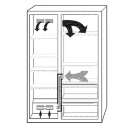
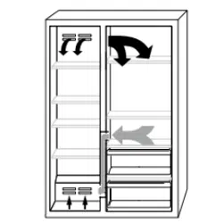
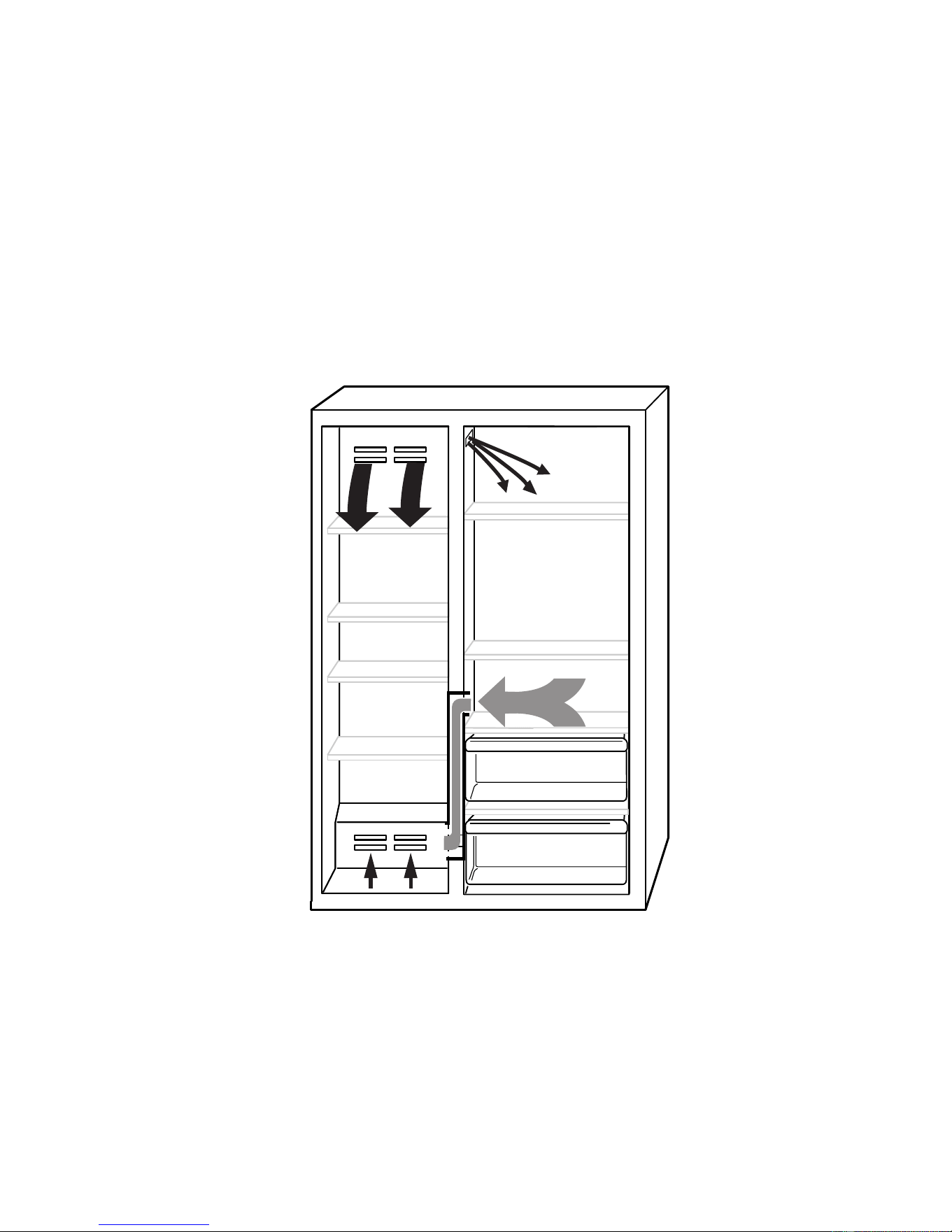
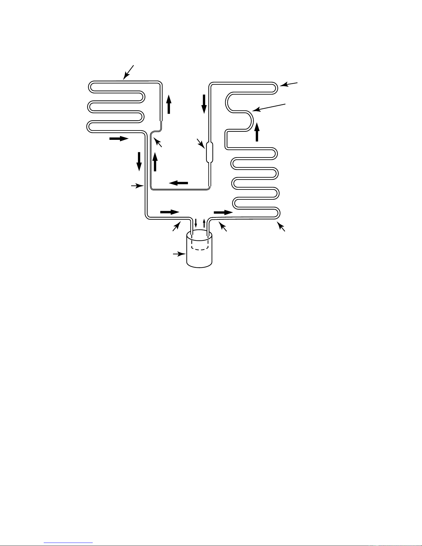
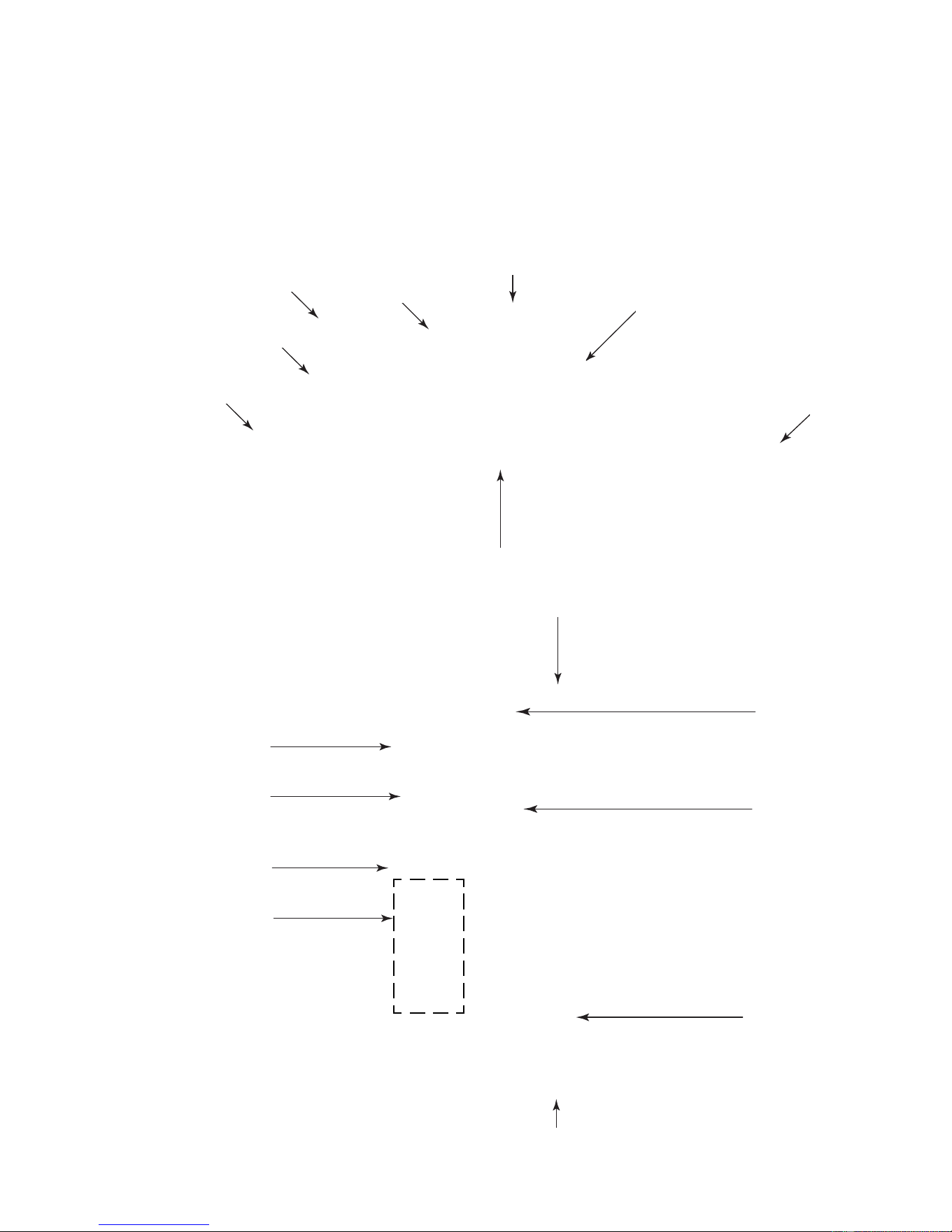
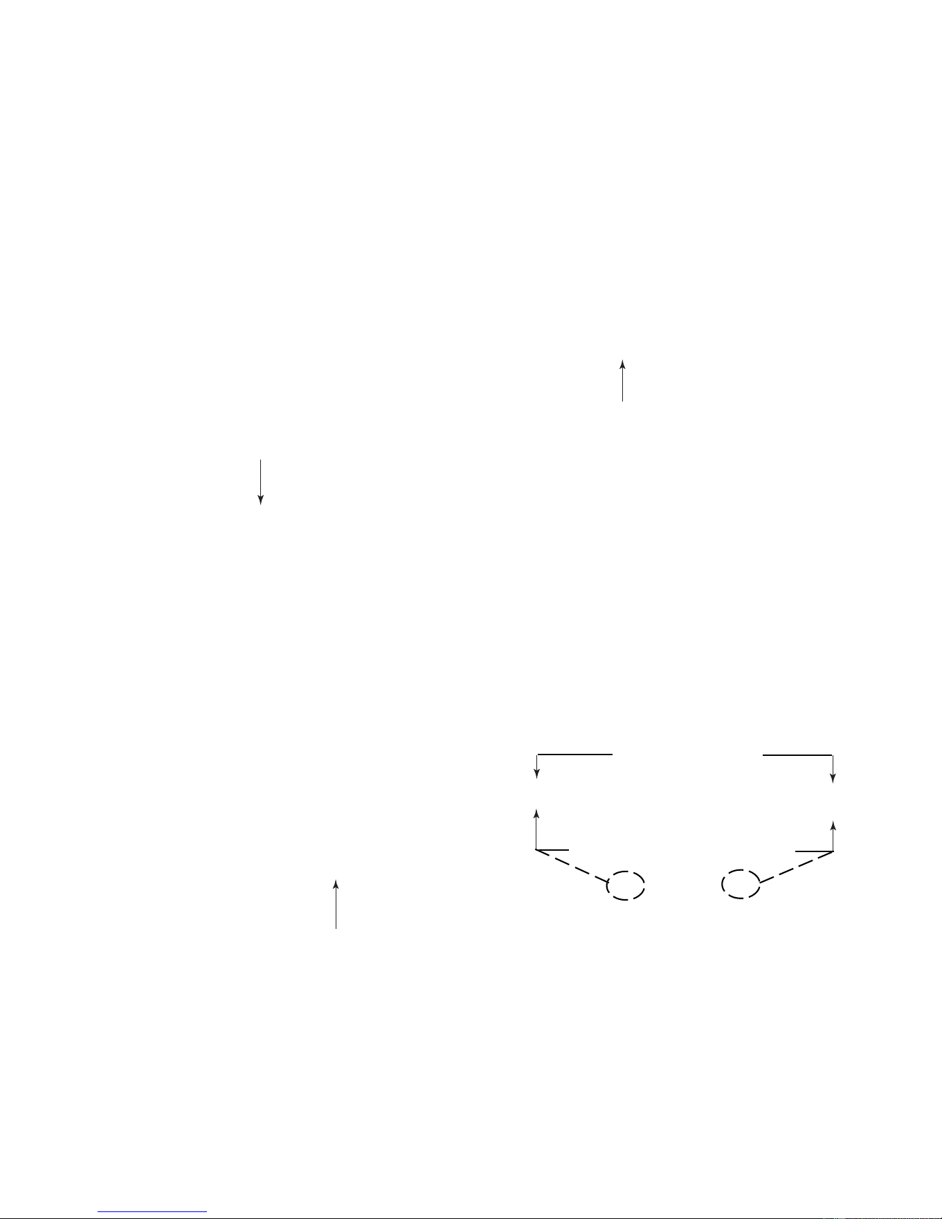
AIR CIRCULATION
In order to ensure the proper refrigerator and
freezer compartment temperatures, air must
be able to flow between the two sections.
Air enters the bottom of the freezer compart-
ment and moves up through the evaporator.
Some of the cooled air from the evaporator is
directed back into the freezer, and the rest
goes into the refrigerator through the motor-
ized air door. The refrigerator air then returns to
the freezer through the bottom air return (see
the illustration below).
It is important not to block any of the vents with
food items. If the vents are blocked, airflow will
be restricted, and the temperature manage-
ment system will not function properly.
IMPORTANT: Because air circulates between
both sections, any odors formed in one sec-
tion will transfer to the other. Keep both sec-
tions clean, and wrap or cover foods tightly to
prevent odors from occurring.
Downloaded from www.ManualsFile.com manuals search engine
4-1
COMPONENT LOCATIONS
This section instructs you on how to service each component inside the refrigerator/freezer. The
components and their locations are shown below.
COMPONENT ACCESS
Freezer Thermistor
Evaporator Fan Motor
Bimetal
Defrost Heater
Evaporator
Refrigerator
Thermistor
Touch Control Assembly
Ice Maker
Auger Motor
Freezer Door
Switch
Inverter Assembly
Compressor
Condenser Fan Motor
Refrigerator Door
Switch
Power Switch
Main Control
Board Assembly
Filter/Drier
Motorized
Air Door
Water
Reservoir
Water Valve
Downloaded from www.ManualsFile.com manuals search engine
4-2
REMOVING THE UNIT COMPARTMENT COVER
NOTE: Sharp edges may be present.
1. Unplug the refrigerator or disconnect the
power.
2. Lift the main decorative panel to unhook it
and remove the panel.
3. Lift and remove the louvered decorative
panel.
Electrical Shock Hazard
Disconnect power before servicing.
Replace all panels before operating.
Failure to do so can result in death or
electrical shock.
Main Decorative Panel
Louvered Decorative Panel
4. Remove the two hex-head screws from
the air diverter and remove the diverter.
5. Remove the nine hex-head screws from
the unit compartment front cover, and pull
the cover forward out of the way.
Air Diverter & 2 Screws
Unit Compartment Front Cover
NOTE: If there is less than 3″ above the top of
the unit compartment cover, perform Method A
to remove the cover. If there is at least 3″ above
the top of the unit compartment cover, Method
B will allow you to remove the cover without
pulling out the refrigerator.
Tip Over Hazard
Refrigerator is top heavy and tips easily
when not completely installed.
Keep door taped closed until refrigerator
is completely installed.
Use two or more people to move and
install refrigerator.
Failure to do so can result in death or
serious injury.
Downloaded from www.ManualsFile.com manuals search engine
4-3
METHOD A
1. Pull the refrigerator out of its mounting
location so you can access the rear of the
unit.
2. Remove the left and right hex-head screws
(one on each side) from the front corners
of the unit compartment cover.
METHOD B
1. Remove the left and right hex-head screws
(one on each side) from the front corners
of the unit compartment cover (see the top
left photo).
2. Remove the four hex-head screws (two on
each side) from the rear flanges of the unit
compartment cover. NOTE: You will need
a 24″ hex-head socket extension with a
magnetic tip to remove these screws.
3. Remove the left and right hex-head screws
from the rear channels of the unit compart-
ment cover.
Right Corner
Screw
4. Lift the unit compartment cover up, and
pull it forward off the refrigerator.
Left Rear
Channel Screw
3. Lift the unit compartment cover up, and
pull it forward off the refrigerator.
REASSEMBLY NOTE: When you reinstall the
unit compartment cover, make sure that the
two unit compartment cover tabs slide under
the rear cover flange, as shown below. This will
provide the proper air flow.
24″ Extension
Slide Tabs Under Rear Flanges
Rear Cover Flanges
Unit Compartment
Cover
Downloaded from www.ManualsFile.com manuals search engine
4-4
REMOVING A DOOR SWITCH, THE POWER SWITCH,
THE INVERTER ASSEMBLY, AND
THE MAIN CONTROL BOARD ASSEMBLY
NOTE: Sharp edges may be present.
1. Unplug the refrigerator or disconnect the
power.
2. Remove the main and louvered decora-
tive panels (see page 4-2).
Electrical Shock Hazard
Disconnect power before servicing.
Replace all panels before operating.
Failure to do so can result in death or
electrical shock.
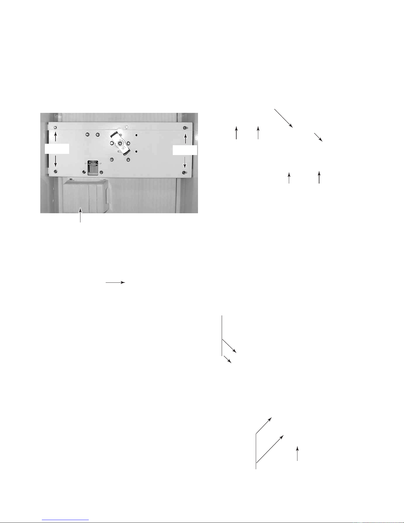
Hex-Head Bolts
Bracket
b) Remove the two hex-head screws from
the door switch cover and remove the
cover.
Door Switch Cover Screw (1 of 2)
c) Disconnect the wire connectors from
the door switch terminals.
d) Press in on the locking arms and push
the switch out of the bracket.
Wire Connectors
Locking Arm
Door Switch
3. To remove a door switch (Original De-
sign):
a) Remove the two hex-head bolts from
the door switch bracket and turn the
bracket over.
Power Switch
Main Control Board Assembly
Inverter Assembly
Downloaded from www.ManualsFile.com manuals search engine
4-5
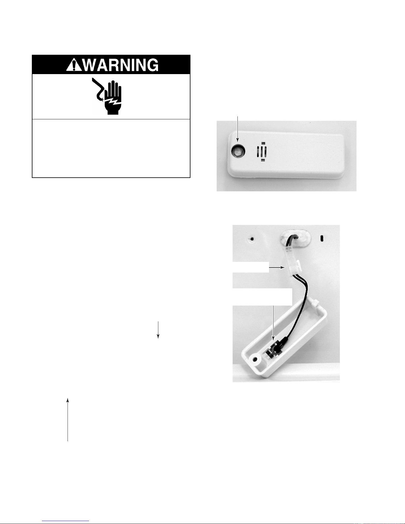
4. To remove a door switch (Revised De-
sign):
a) Remove the two hex-head screws from
the door switch cover and remove the
cover.
Door Switch Cover Screws
b) Disconnect the wire connectors from
the door switch terminals.
c) Press in on the locking arms and push
the switch out of the bracket.
Door Switch
5. To remove the power switch:
a) Remove the unit compartment front
cover, pull the cover forward, and turn
it over (see step 5 on page 4-2 for the
procedure).
b) Remove the four wire connectors from
the power switch terminals.
c) Press in on the locking arms and push
the switch out of the cover opening.
Power Switch
Locking
Arms
Locking
Arms
6. To remove the inverter assembly:
a) Remove the two hex-head screws from
the air diverter and remove the diverter.
b) Remove the three remaining hex-head
screws from the front guard and re-
move the guard.
Screw
Screw
Air
Diverter
Front
Guard
c) Remove the hex-head screw from the
front of the inverter assembly.
Screw
Inverter
Assembly
Retaining Bracket
Continued on the next page.
Downloaded from www.ManualsFile.com manuals search engine

4-6
e) Disconnect the two wire connectors
and the hex-head screw from the green
ground wire coming from the inverter
assembly.
2 Wire Connectors
g) Disconnect the green ground wire and
the 3-pin inverter output lead from the
compressor.
h) Loosen the strain relief screw from the
compressor terminal cover, remove the
wire, and remove the inverter assem-
bly.
f) Remove the compressor terminal cover.
To remove the cover, insert a flat-bladed
screwdriver into the top slot, push down
on the screwdriver to release the catch,
and then rotate the cover forward at the
top and lift it off the bottom catch.
Compressor
Terminal Cover
Ground
Wire Screw
Ground Wire
& 3-Pin Lead
Cover Strain Relief
d) Pull the inverter assembly forward so it
is free of the retaining bracket, rotate
the box so you can access the rear
mounting screw, and remove the screw.
Rear
Screw
Retaining Bracket
Downloaded from www.ManualsFile.com manuals search engine
4-7
Electrical Shock Hazard
Connect green ground wire to ground
screw.
Failure to do so can result in death or
electrical shock.
REASSEMBLY NOTE: Be sure to reconnect
the green ground wires; one to the compressor
terminal, and the other to the chassis (see the
previous steps).
7. To remove the main control board as-
sembly:
a) Remove the unit compartment cover
(see pages 4-2 & 4-3 for the proce-
dures).
b) Remove the two hex-head screws from
the rear of the main control board as-
sembly enclosure, and position it so
you can access the board.
c) Remove the wire connectors from the
main control board assembly.
Wire Connectors
Screws At Rear Of Enclosure
d) Remove the main control board from
the five standoffs. Press in on the lock-
ing tab on each standoff to release the
board.
Press Locking Tab
On Standoff
Downloaded from www.ManualsFile.com manuals search engine
4-8
REMOVING THE CONDENSER FAN MOTOR
NOTE: Sharp edges may be present.
1. Unplug the refrigerator or disconnect the
power.
2. Remove the main and louvered decora-
tive panels (see page 4-2).
3. Remove the unit compartment cover (see
pages 4-2 & 4-3 for the procedures).
Electrical Shock Hazard
Disconnect power before servicing.
Replace all panels before operating.
Failure to do so can result in death or
electrical shock.
8. Remove the two hex-head screws from
the condenser fan motor and remove the
motor from the bracket.
Condenser Fan Motor
Viewed From Back Of Unit
Wire
Connector
4. Remove the two hex-head screws from
the fan motor bracket (see the photo at the
top of the next column).
5. Disconnect the wire connector from the
condenser fan motor.
Fan Motor Bracket Screws
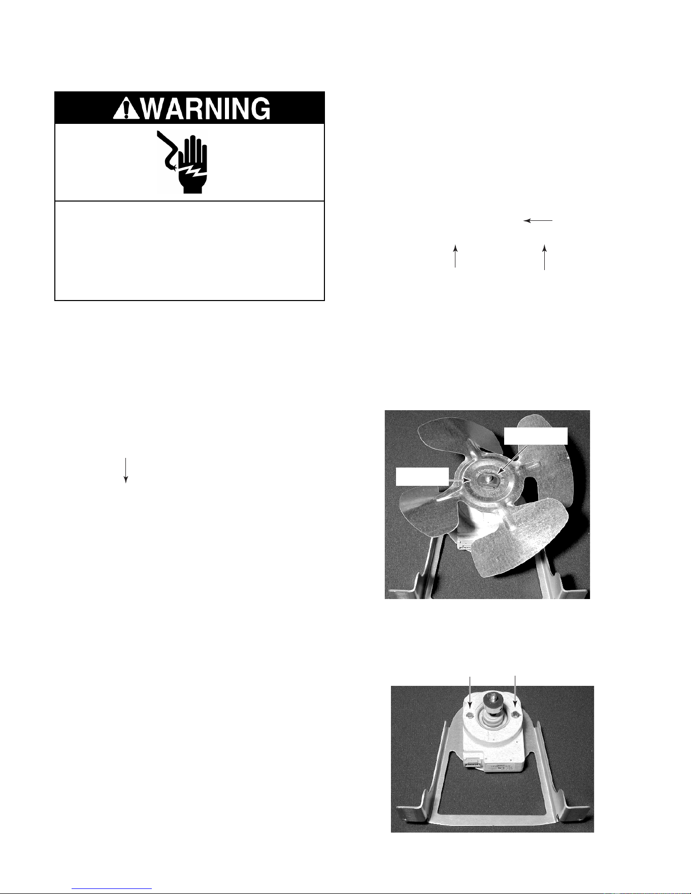
6. Lay the condenser fan motor on a work
surface with the fan blade facing up.
7. Remove the speed nut from the condenser
fan blade and remove the blade from the
motor shaft. NOTE: Be sure to position the
fan blade with the “Nut Side” facing as
shown when you reinstall it later.
Nut Side
Speed Nut
Motor Screws
Downloaded from www.ManualsFile.com manuals search engine
4-9
REMOVING THE COMPRESSOR AND FILTER/DRIER
NOTE: Sharp edges may be present.
1. Unplug the refrigerator or disconnect the
power.
2. Remove the main and louvered decora-
tive panels (see page 4-2).
3. Remove the unit compartment cover (see
pages 4-2 & 4-3 for the procedures).
NOTE: The compressor location is shown on
page 4-8.
4. Remove the compressor terminal cover.
To remove the cover, insert a flat-bladed
screwdriver into the top slot, push down on
the screwdriver to release the catch, and
then rotate the cover forward at the top
and lift it off the bottom catch.
Electrical Shock Hazard
Disconnect power before servicing.
Replace all panels before operating.
Failure to do so can result in death or
electrical shock.
Compressor
Terminal Cover
7. Access the sealed system and discharge
the refrigerant into an approved recovery
system.
8. Unbraze the suction and discharge lines
from the compressor.
9. Cut the filter/drier from the system (do not
use a torch to remove the filter/drier).
6. Loosen the strain relief screw from the
compressor terminal cover and remove
the wire.
Ground Wire
& 3-Pin Lead
Cover Strain Relief
10. Remove the four mounting bolts and rub-
ber grommets from the compressor.
11. Lift the old compressor from the refrigera-
tor and replace it.
5. Disconnect the green ground wire and the
3-pin inverter output lead from the com-
pressor (see the photo at the top right).
Filter/Drier
Suction
Discharge
Downloaded from www.ManualsFile.com manuals search engine

4-10
6. Lift and unhook the two evaporator cover
tabs, then lower the cover until the top
edge clears the air duct, and slide the
cover up and out of the freezer.
REMOVING THE BIMETAL, THE EVAPORATOR FAN
MOTOR, THE DEFROST HEATER, AND THE EVAPORATOR
NOTE: Sharp edges may be present.
1. Unplug the refrigerator or disconnect the
power.
2. Open the freezer door.
3. Remove the freezer shelves that are over
the evaporator cover.
4. Remove the indicated two shelf mounting
studs.
Evaporator
Cover
Shelf Studs
5. Remove the eight hex-head screws from
the evaporator cover.
Screws
(2 of 8)
Unhook Evaporator
Cover Tabs
7. To remove the bimetal:
a) Unclip the bimetal from the evaporator
inlet tubing.
b) Follow the instructions that were sup-
plied with the replacement bimetal to
connect the wires.
Bimetal
Electrical Shock Hazard
Disconnect power before servicing.
Replace all panels before operating.
Failure to do so can result in death or
electrical shock.
Clip
Downloaded from www.ManualsFile.com manuals search engine
4-11
8. To remove the evaporator fan motor:
a) Pull the fan blade off the motor shaft.
b) Unclip the motor.
c) Disconnect the wire connector from the
terminals.
Unclip Motor
Pull Fan Blade Off Motor Shaft
Wire Connector
d) Remove the isolator from the motor.
Isolator
Evaporator
Fan Motor
9. To remove the defrost heater:
a) Remove the two hex-head screws from
the evaporator fan motor shroud.
b) Lift the evaporator fan motor shroud
and disconnect the evaporator fan motor
connector (see the photo to the left).
c) Unclip the bimetal from the evaporator
inlet tubing.
Evaporator Fan Motor
Shroud Screws
Foam Blocks
e) Remove the evaporator fan motor
shroud and the two side foam blocks.
Continued on the next page.
Bimetal
d) Disconnect the terminal connector and
the two defrost heater wires from the
harness connector.
Defrost Heater Wires
Terminal Connector
Downloaded from www.ManualsFile.com manuals search engine
4-12
j) Unfasten the two metal clips from the
right side, and slide the defrost heater
down and off the evaporator.
g) Remove the foam block from the right
side of the evaporator.
NOTE: Be very careful not to over-bend
the refrigerant tubing.
h) Lift the evaporator up slightly and un-
hook it from the liner, then pull the
bottom of the evaporator toward the
front of the unit.
Right Side Clip
Defrost Heater
Right Foam Block
f) Remove the hex-head screws from the
right evaporator cover mounting bracket
and remove the bracket. Be careful not
to drop the screws down the drain hole
at the bottom of the liner. Cover the hole
with a cloth.
Right Evaporator Cover
Mounting Bracket
i) Bend the two hangers at the bottom of
the evaporator.
Bend The Two Hangers
Downloaded from www.ManualsFile.com manuals search engine

4-13
10. To remove the evaporator:
a) Remove the defrost heater from the
evaporator (see pages 4-11 & 4-12).
b) Access the sealed system and dis-
charge the refrigerant into an approved
recovery system.
c) Remove and replace the evaporator.
REASSEMBLY NOTES:
1. The evaporator fan motor shroud has a
foam insert on each side. Note the position
of these inserts in the photo and reinstall
them correctly, as shown.
2. Be sure to reinstall the right foam block at
the location shown below.
Defrost
Heater
Evaporator
Evaporator Fan Motor Shroud
Foam Blocks
Right Foam Block
Downloaded from www.ManualsFile.com manuals search engine
4-14
REMOVING THE TOUCH/DISPLAY BOARD
& THE MOTORIZED AIR DOOR
NOTE: Sharp edges may be present.
1. Unplug the refrigerator or disconnect the
power.
2. Open the refrigerator door and remove the
items from the top shelf. If necessary,
remove the top shelf so you can easily
access the touch control assembly or the
motorized air door. The locations are
shown below.
Electrical Shock Hazard
Disconnect power before servicing.
Replace all panels before operating.
Failure to do so can result in death or
electrical shock.
c) Disconnect the wire connector from the
end of the touch/display board.
3. To remove the touch/display board:
a) Remove the three hex-head screws
from the back of the touch control as-
sembly and lower the assembly.
Touch Control Assembly
b) Disconnect the two wire connectors
from the touch control assembly and
remove the assembly from the refrig-
erator.
Wire Connectors
Wire Connector
d) Unclip the touch/display board from the
locking tabs and remove the board.
Board Clips
Motorized Air Door
3 Screws At Back Of Control
Downloaded from www.ManualsFile.com manuals search engine

4-15
4. To remove the motorized air door:
a) Remove the hex-head screws from the
motorized air door cover and remove
the cover.
c) Disconnect the wire connector from the
motorized air door and remove it. RE-
ASSEMBLY NOTE: Be sure to position
the motorized air door with the motor
and wires as shown in the bottom left
photo.
b) Pull the motorized air door out of the
refrigerator liner opening.
Screw
Motorized Air Door Cover
Motorized Air Door
Wire Connector
Screw
Downloaded from www.ManualsFile.com manuals search engine
4-16
REMOVING THE ICE MAKER AND
THE AUGER MOTOR & CRUSH/CUBE SOLENOID
Electrical Shock Hazard
Disconnect power before servicing.
Replace all panels before operating.
Failure to do so can result in death or
electrical shock.
NOTE: Sharp edges may be present.
1. Unplug the refrigerator or disconnect the
power.
2. Open the freezer door and remove the ice
maker shelf and the ice bin.
3. To remove the ice maker:
a) Remove the bottom screw from the ice
maker bracket.
Ice Maker
Auger Assembly
Bottom Bracket Screw
b) Loosen the two top ice maker bracket
screws.
c) Lift the brackets at the top of the ice
maker off the screws, disconnect the
electrical harness connector, and re-
move the ice maker.
Top Bracket
Screws
Water Fill Tube
Inside Fill Cup
NOTE: When you reinstall the ice maker, make
sure that the end of the water fill tube is posi-
tioned inside the fill cup (see the photo above).
Ice Bin
Ice Maker
Shelf
Downloaded from www.ManualsFile.com manuals search engine
4-17
4. To remove the auger motor or crush/
cube solenoid:
a) Remove the light shield and the bulb
from the socket.
b) Remove the four hex-head screws from
the auger assembly and pull the as-
sembly forward.
Light Shield & Bulb
Auger Assembly
c) Disconnect the electrical harness con-
nector, and remove the auger assem-
bly.
Screws
Screws
Harness Connector
d) To remove the auger, unscrew the drive
coupler (left-hand threads) and remove
it from the motor shaft.
e) Remove the three auger motor hex-
head screws from the housing.
Drive Coupler
Remove
f) Disconnect the wires from the auger
motor terminals.
g) Disconnect the wires from the solenoid
terminals.
h) Remove the green ground wire from
the ground terminal.
i) To remove the crush/cube solenoid,
remove the two hex-head mounting
screws from the housing (see above).
Auger Motor Wires
Solenoid Screws
Solenoid Wires
Auger Motor
Screw (2 of 3)
Ground Wire
Downloaded from www.ManualsFile.com manuals search engine
4-18
REMOVING A THERMISTOR
NOTE: Sharp edges may be present.
1. Unplug the refrigerator or disconnect the
power.
NOTE: The refrigerator and freezer thermistors
are identical and are removed in the same
manner.
2. Depending on the thermistor, open the
freezer or refrigerator door, and remove
any items from the shelf that are in front of
the thermistor. It may be necessary to
remove the shelf as well. The thermistor
locations are shown below.
Electrical Shock Hazard
Disconnect power before servicing.
Replace all panels before operating.
Failure to do so can result in death or
electrical shock.
4. Disconnect the 2-wire connector and re-
move the thermistor.
3. Remove the hex-head screw from the
thermistor cover. Pull the cover forward at
the screw end, and unhook the tab from
the slot at the other end of the thermistor
cover.
Refrigerator / Freezer
Thermistor Cover
Screw
Connector
Refrigerator / Freezer
Thermistor
Freezer Thermistor
Refrigerator Thermistor
Downloaded from www.ManualsFile.com manuals search engine
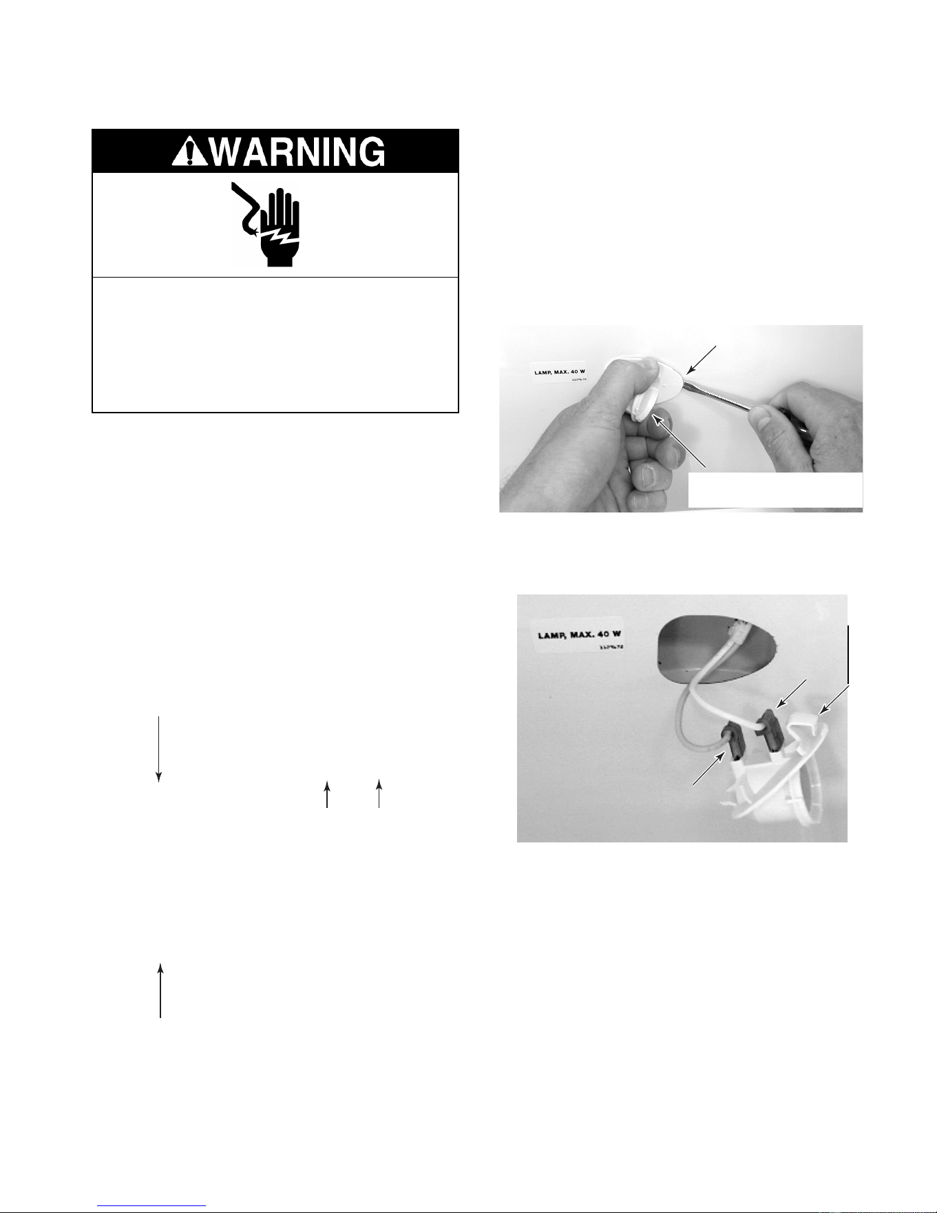
4-19
REMOVING A LIGHT SOCKET
NOTE: Sharp edges may be present.
1. Unplug the refrigerator or disconnect the
power.
NOTE: The refrigerator and freezer light sock-
ets are identical and are removed in the same
manner.
2. Depending on the light, open the freezer
or refrigerator door, and remove any items
from the shelf that are in front of the light.
It may be necessary to remove the shelf as
well. The light locations are shown below.
Electrical Shock Hazard
Disconnect power before servicing.
Replace all panels before operating.
Failure to do so can result in death or
electrical shock.
3. Remove the light shield.
4. Remove the bulb from the socket.
5. Grasp the light socket by the rounded
portion and pull out on the narrow end,
while pressing the locking arm (see the
photo below) with a screwdriver blade.
Pull out on the socket until it disengages
from the opening.
Press In On Locking
Arm At Narrow End
Grasp Rounded Portion
Here & Pull Out
6. Disconnect the two wires from the light
socket terminals.
Wire
Wire
Locking Arm
Freezer Light
Freezer Light
Refrigerator Lights
Downloaded from www.ManualsFile.com manuals search engine
4-20
REMOVING THE WATER RESERVOIR
Electrical Shock Hazard
Disconnect power before servicing.
Replace all panels before operating.
Failure to do so can result in death or
electrical shock.
NOTE: Sharp edges may be present.
1. Unplug the refrigerator or disconnect the
power.
3. Use the leveling screws and lower the
refrigerator onto the four rollers.
Base Grille
NOTE: If the water reservoir tubing located
inside the refrigerator compartment becomes
damaged, you can cut and splice a new reser-
voir in its place using two 5/16″ unions
(#4388201). If the tubing located under the
refrigerator is defective, it will be necessary to
remove the unit from its mounting location to
repair it. If that is the case, use the following
procedure.
2. Remove the two screws from the base
grille and remove the grille.
Screw
Screw
Tip Over Hazard
Refrigerator is top heavy and tips easily
when not completely installed.
Keep door taped closed until refrigerator
is completely installed.
Use two or more people to move and
install refrigerator.
Failure to do so can result in death or
serious injury.
4. Pull the refrigerator out of its mounting
location.
Leveling Screws
Rear Front
NOTE: The water reservoir and water valve
locations are shown below.
Water Reservoir
Water Valve
Unit Shown Tipped Back 45˚
Leveling Screws
Downloaded from www.ManualsFile.com manuals search engine

4-21
Pull Tubing Up Through Grommet
6. Use a putty knife, slide the retainer clips off
the door channel, and pull the water line
out from under the channel.
Door Channel
Clip
9. Reach under the front of the refrigerator
and remove the water reservoir outlet tub-
ing nut from the water valve and remove
the nut from the end of the tubing.
7. Position a container to catch the water in
the next step.
8. Disconnect the nut from the union and
remove the nut from the end of the water
reservoir tubing.
Union Nut
5. Unhook the front edge of the drip pan and
pull it out the front of the refrigerator.
Unhook Front
10. Remove the crisper and bottom shelves
from the refrigerator compartment.
11. Remove the hex-head screw from the
water reservoir tubing strap.
12. Pull the ends of the water reservoir tubing
up through the grommet.
Drip Pan
Water Reservoir Tubing Nut
Water Reservoir Tubing Strap
Downloaded from www.ManualsFile.com manuals search engine
4-22
REMOVING THE WATER VALVE
Electrical Shock Hazard
Disconnect power before servicing.
Replace all panels before operating.
Failure to do so can result in death or
electrical shock.
5. Disconnect the 1/2″ nut from the water
valve inlet.
6. Remove the two hex-head mounting
screws from the water valve mounting
bracket.
NOTE: Sharp edges may be present.
1. Unplug the refrigerator or disconnect the
power.
2. Remove the two screws from the base
grille and remove the grille.
3. Turn off the water supply to the refrigera-
tor.
Base Grille
Screw
Screw
NOTE: The water valve location is shown be-
low.
Water Valve
4. Position a container to catch the water in
the next step.
7. Pull the water valve forward and discon-
nect the water outlet tubing nut(s).
8. Disconnect the solenoid connector(s)
from the water valve terminal(s).
Water Valve
Water Valve
Inlet Tubing
Water Valve
Bracket Screws
Solenoid Connectors
Water Outlet Tubing Nuts
Downloaded from www.ManualsFile.com manuals search engine
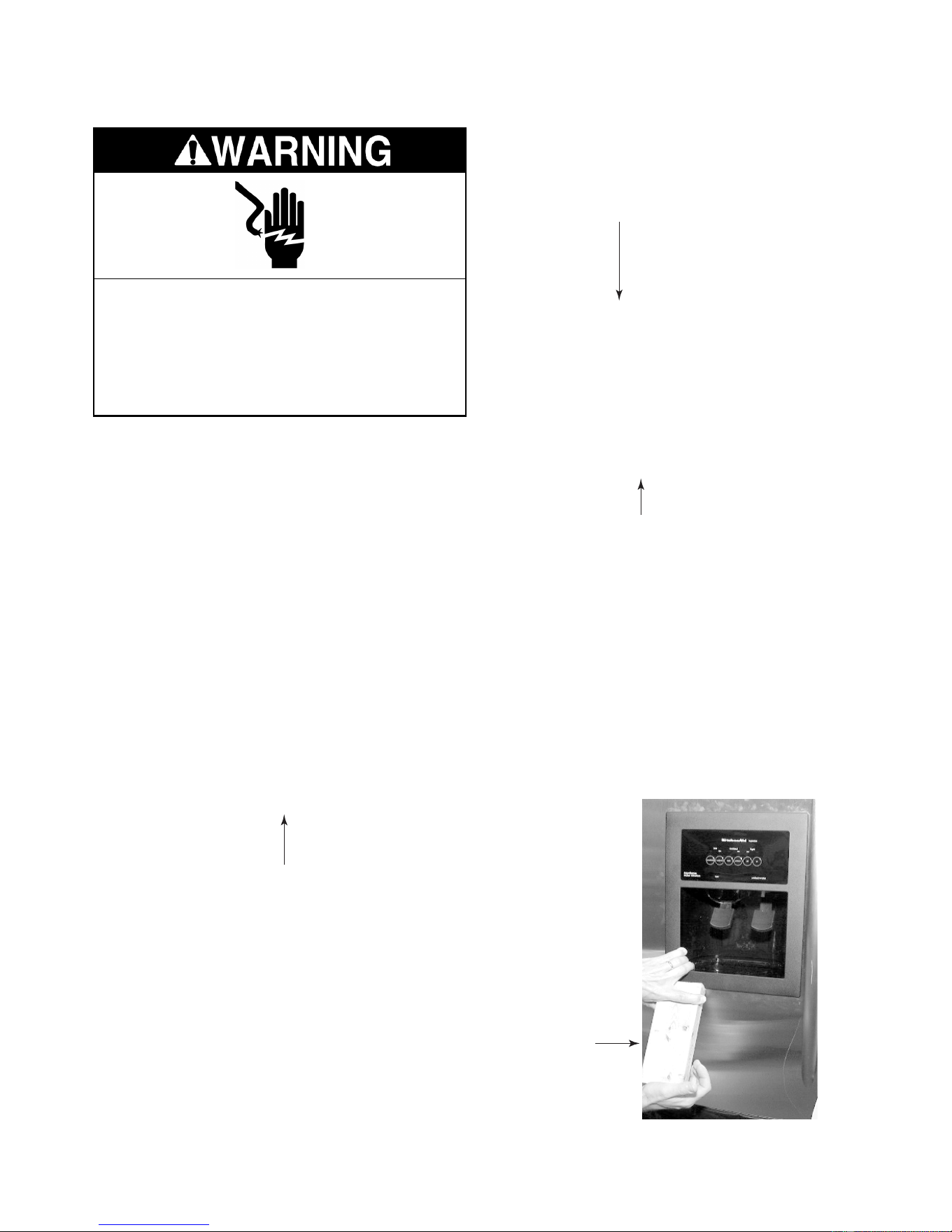
4-23
REMOVING THE WATER & ICE DISPENSER
Electrical Shock Hazard
Disconnect power before servicing.
Replace all panels before operating.
Failure to do so can result in death or
electrical shock.
NOTE: Sharp edges may be present.
1. Unplug the refrigerator or disconnect the
power.
2. Remove the drip tray from the water & ice
dispenser.
Drip Tray
c) Bow the front panel out at the center
and remove it from the top and bottom
channels of the water & ice dispenser.
Bottom Channel
Top Channel
NOTE: There are two types of water and ice
dispensers: one for doors with panels, and the
other for stainless steel trimless doors. The
front panels for each type of door are removed
differently. Refer to step 3 for paneled doors, or
step 4 for stainless steel trimless doors, to
remove either type of front panel.
4. For stainless steel trimless doors:
a) Position a wood block along the bottom
edge at the left corner of the water & ice
dispenser.
b) Use a rubber mallet, and hit the block
while you pull out at the bottom, so that
the cover tab releases the panel from
the dispenser housing.
Continued on the next page.
Wood Block
3. For paneled doors:
a) Partially open the freezer door.
b) Remove the screws from the freezer
door handle and remove the handle.
d) Proceed to step 5 on the next page to
remove the dispenser.
Downloaded from www.ManualsFile.com manuals search engine
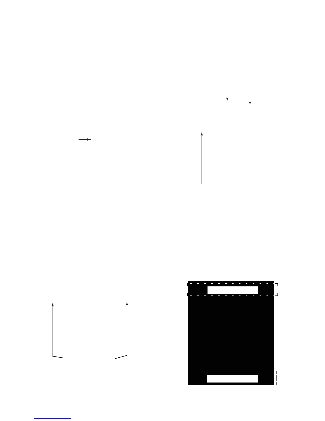
4-24
c) Disconnect the three wire connectors
and remove the subpanel.
b) Remove the two hex-head screws from
the switch subpanel, pull the panel for-
ward, and turn it over.
Hex-Head Screws
2 Wire Connectors
Wire Connector
Wire Connector
c) Repeat the previous step for the other
corner of the front panel.
d) Pull the bottom of the front panel out
and then down to remove it from the
dispenser.
5. To remove the dispenser:
a) Disconnect the front panel wire con-
nector and remove the panel.
REASSEMBLY NOTE: To reinstall the front
panel on stainless steel trimless doors:
1. Fit the top edge of the panel into the door
opening.
2. Place a folded towel over the top edge of
the panel and hit it with the rubber mallet
you used earlier to seat it in the door.
3. Place the folded towel along the bottom
edge of the front panel and seat it with the
mallet.
Seat This Area Last
Seat This Area First
Downloaded from www.ManualsFile.com manuals search engine
4-25
REMOVING A DOOR GASKET
Electrical Shock Hazard
Disconnect power before servicing.
Replace all panels before operating.
Failure to do so can result in death or
electrical shock.
5. Starting at the top of the door, install the
new door gasket by sliding the lip of the
gasket under the metal retaining strip.
6. Tighten the top of the metal retaining strip
just enough to hold the gasket in place.
7. Starting at the center of the gasket on the
right side, work toward the top of the door,
and slide the lip of the gasket under the
metal retaining strip, tightening the strip as
you go. Make sure that the back edge of
the gasket butts up against the handle
bracket from top to bottom.
8. Close the door and check the gasket to
make sure that it seals tightly against the
frame. If the gasket is buckled, loosen the
metal retaining strip, and smooth the area.
9. Tighten all of the hex-head screws se-
curely.
Pull Lip Of
Gasket Out
From Under
Metal Retain-
ing Strip
Metal
Retaining
Strip
Gasket
NOTE: Sharp edges may be present.
1. Unplug the refrigerator or disconnect the
power.
2. Open the door for the gasket you intend to
replace.
3. Fold the door gasket back and loosen the
hex-head screws around the perimeter of
the door.
4. Pull the lip of the gasket out from under the
metal retaining strip and remove the gas-
ket.
Hex-Head
Screw
Hex-Head
Screw
Downloaded from www.ManualsFile.com manuals search engine
4-26
REMOVING THE FREEZER OR REFRIGERATOR DOOR
NOTE: Sharp edges may be present.
1. Unplug the refrigerator or disconnect the
power.
2. Remove the main and louvered decora-
tive panels (see page 4-2).
NOTE: If the freezer door has a water and ice
dispenser, it will be necessary to remove the
refrigerator from its mounting location in order
to disconnect the wiring harness. To do this,
perform step 3. If the freezer door does not
have a water and ice dispenser, skip step 3,
and proceed to step 4, on page 4-28.
3. To remove a freezer door with a water &
ice dispenser:
a) Remove the two screws from the base
grille and remove the grille.
Electrical Shock Hazard
Disconnect power before servicing.
Replace all panels before operating.
Failure to do so can result in death or
electrical shock.
Base Grille
Screw
Screw
Tip Over Hazard
Refrigerator is top heavy and tips easily
when not completely installed.
Keep door taped closed until refrigerator
is completely installed.
Use two or more people to move and
install refrigerator.
Failure to do so can result in death or
serious injury.
c) Pull the refrigerator out of its mounting
location.
b) Use the leveling screws and lower the
refrigerator onto the four rollers.
Leveling Screws
Rear Front
Downloaded from www.ManualsFile.com manuals search engine
4-27
h) Remove the hex-head screw from the
green ground wire on the water & ice
dispenser wiring harness.
d) Disconnect the water & ice dispenser
electrical harness connector at the back
of the refrigerator.
Water & Ice Dispenser
Electrical Harness Connector
Door Channel
Clip
f) Position a container to catch the water
in the next step.
e) Use a putty knife, slide the retainer clips
off the door channel, and pull the wiring
and water line out from under the chan-
nel.
g) Disconnect the water reservoir tubing
nut at the union and remove the nut
from the end of the tubing.
Water & Ice Dispenser
Electrical Harness
Water Reservoir
Union Nut
Harness Ground
Continued on the next page.
Electrical Shock Hazard
Connect green ground wire to ground
screw.
Failure to do so can result in death or
electrical shock.
Downloaded from www.ManualsFile.com manuals search engine

4-28
NOTE: The door spring will remain under slight
tension when the door is closed.
6. Use a pair of pliers and lift the end of the
linkage off the square post.
4. Remove the door switch & bracket for the
refrigerator or freezer door (see page 4-4
for the procedure).
5. With the door closed, remove the hex-
head screw from the door linkage at the
top of the door.
Door Linkage Screw
7. Place a support under the door that you
are removing to prevent it from falling.
8. Remove the four hex-head screws from
the door hinge.
Lift Door
Linkage Off Post
Disconnect End
Of Spring
9. Grasp the door firmly and lift it off the
bottom hinge pin.
Door Hinge
Screw
(1 of 4)
Downloaded from www.ManualsFile.com manuals search engine
5-1
COMPONENT TESTING
Before testing any of the components, perform
the following checks:
• The most common cause for control failure is
corrosion on connectors. Therefore, discon-
necting and reconnecting wires will be nec-
essary throughout test procedures.
Refer to page 4-18 for the procedure for servic-
ing a thermistor.
1. Run the diagnostics tests (see page 6-1)
and test the thermistors in steps 01 and
02.
NOTE: For accurate temperature/resistance
readings, continue with the remaining steps to
check the resistance of the thermistor(s).
2. Unplug the refrigerator or disconnect the
power.
3. Disconnect the thermistor wire connector
from the main harness.
4. Set the ohmmeter to the R x 1K scale.
5. Insert the test probes into the two connec-
tor pins of the thermistor connector.
THERMISTOR
NOTE: If the resistance of the thermistor(s)
was normal, perform the following voltage test.
1. Set the voltmeter to read a maximum
voltage of 10 volts DC.
2. Connect power to the refrigerator and
allow it to enter the “cooling” mode.
3. With the thermistor disconnected and the
refrigerator in the cooling mode, touch the
voltmeter test probes to the thermistor
main harness connector pins. The meter
should indicate approximately 5 volts DC.
If the voltage was not present, check for a
thermistor output at the main control board
(see page 5-5).
6. Depending on the temperature, the meter
should indicate within the approximate
range, as shown in the chart below.
• Check all connections before replacing com-
ponents, looking for broken or loose wires,
failed terminals, or wires not pressed into
connectors far enough.
• Resistance checks must be made with power
cord unplugged from outlet, and with wiring
harness or connectors disconnected.
Electrical Shock Hazard
Disconnect power before servicing.
Replace all panels before operating.
Failure to do so can result in death or electrical shock.
TEMPERATURE RESISTANCE TEMPERATURE RESISTANCE
(°°
°°
F)
OHMS (APPROX.)
(°°
°°
F)
OHMS (APPROX.)
–5 25900-27500 4 5 5930-6300
0 22100-23500 50 5190-5510
5 18900-20000 55 4550-4830
10 16200-17200 60 4000-4240
15 13900-14800 65 3520-3730
20 12000-12800 70 3100-3300
25 10400-11000 75 2740-2910
30 8990-9550 80 2430-2580
32 8750 85 2160-2290
35 7800-8290 90 1920-2030
4 0 6800-7220
Downloaded from www.ManualsFile.com manuals search engine
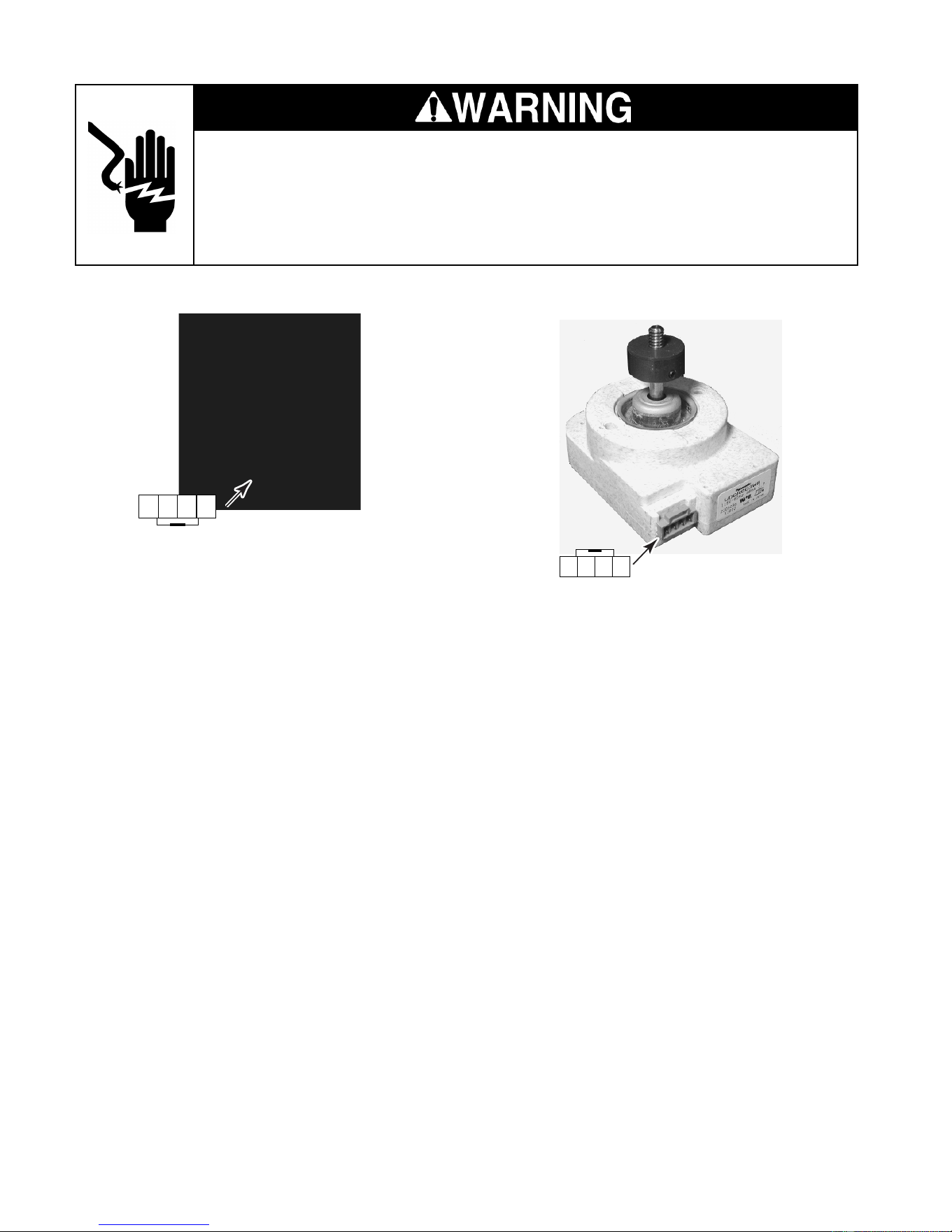
5-2
Electrical Shock Hazard
Disconnect power before servicing.
Replace all panels before operating.
Failure to do so can result in death or electrical shock.
CONDENSER FAN MOTOR
Refer to page 4-8 for the procedure for servic-
ing the condenser fan motor.
1. Run the diagnostics tests (see page 6-1)
and check for the proper operation of the
condenser fan motor in step 04.
NOTE: During the condenser fan motor opera-
tion, 120 volts AC will be present at pins 1 and
4.
1234
EVAPORATOR FAN MOTOR
Refer to page 4-10 for the procedure for servic-
ing the evaporator fan motor.
1. Run the diagnostics tests (see page 6-1)
and check for the proper operation of the
evaporator fan motor in step 03.
NOTE: During the evaporator fan motor opera-
tion, 5 to 17 volts DC will be present at the
yellow and white wires. A constant 12 volts at
the red and white wires will be present anytime
the fan motor is operating. The remaining steps
will allow you to check the resistance of the
evaporator fan motor.
2. Unplug the refrigerator or disconnect the
power.
3. Disconnect the wire connector going to
the evaporator fan motor.
4. Set the ohmmeter to the R x 10K scale.
5. Touch the ohmmeter test probes to pins 1
and 4 of the evaporator fan motor connec-
tor. The meter should indicate approxi-
mately 1400 to 1700 Ω.
1234
Downloaded from www.ManualsFile.com manuals search engine
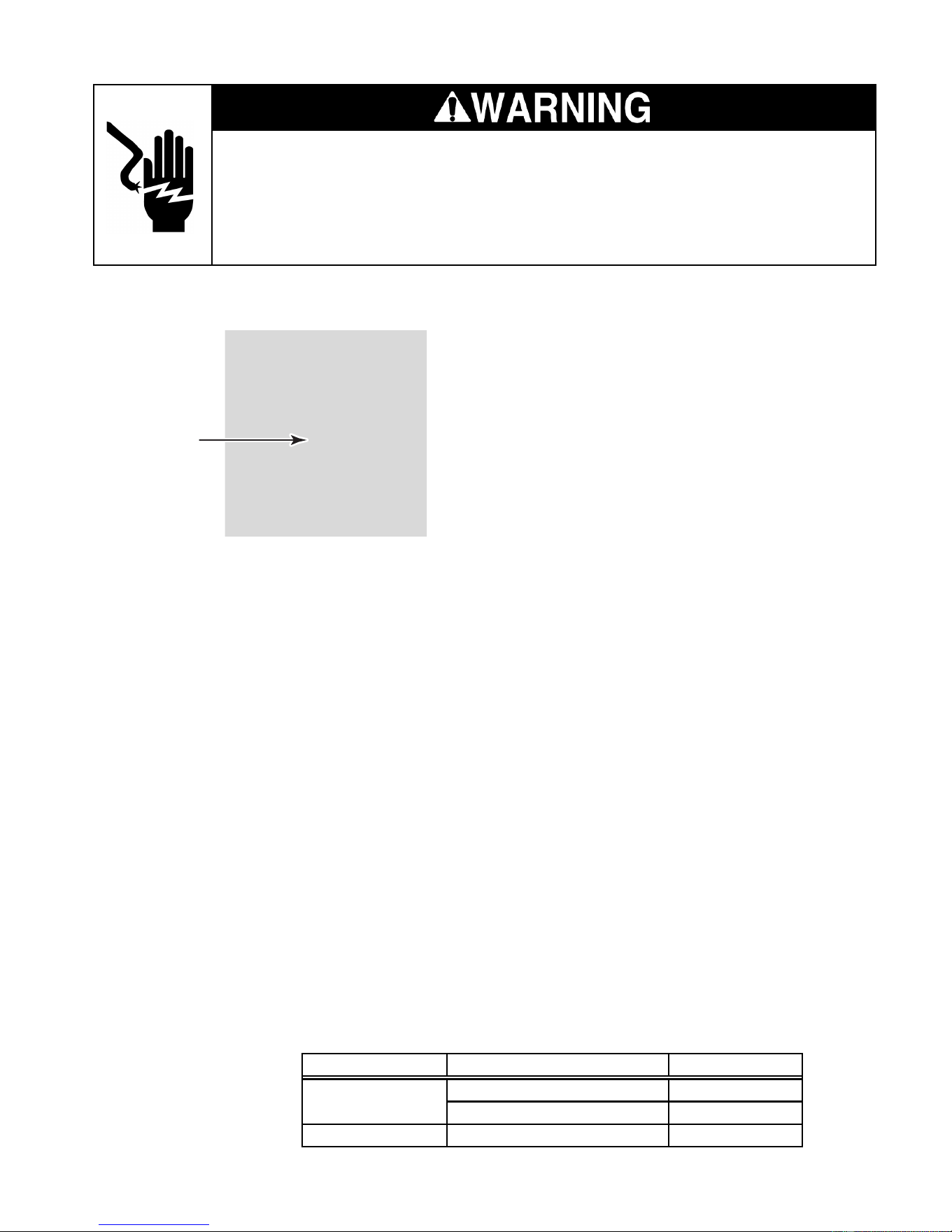
5-3
COMPRESSOR & INVERTER
Refer to pages 4-4 and 4-9 for the procedures
for servicing the inverter and compressor.
1. Run the diagnostics tests (see page 6-1)
and check for the proper operation of the
compressor in step 05.
NOTE: If the compressor does not operate
perform the following steps.
2. Connect power to the refrigerator and
allow it to enter the “cooling” mode.
3. While the refrigerator is in the cooling
mode, the inverter and main control board
voltages should be as shown in the chart
below.
4. Set the voltmeter to read the voltages
shown in the chart.
• If the 3 to 6 volts DC is not present at
the inverter red/white and red wires,
check P7-3 and P7-8 on the main con-
trol board for 3 to 6 volts DC. If the volt-
age is not present, replace the main
control board.
Pins
Electrical Shock Hazard
Disconnect power before servicing.
Replace all panels before operating.
Failure to do so can result in death or electrical shock.
• If the 3 to 6 volts DC is present at the
main control board, continue with step 5.
5. Unplug the refrigerator or disconnect the
power.
6. Disconnect the wire connector going to
the compressor.
7. Set the ohmmeter to the R x 1 scale.
8. Touch the meter leads to any two pins.
The meter should indicate approximately
9 to 10 Ω. Check between each set of pins
to test all three windings.
9. Set the ohmmeter to the highest scale.
10. Touch one meter lead to the cabinet ground
and the other lead to each of the three
compressor terminals. The meter should
indicate an open circuit (infinite).
COMPONENT INPUT/ OUTPUT LOCATIONS VOLTAGES
Red/White & Red Wires 3 To 6 Volts DC
Black & White Wires 120 Volts AC
Main Control Board P7-3 (Red) & P7-8 (Red/White) 3 To 6 Volts DC
Inverter
Downloaded from www.ManualsFile.com manuals search engine
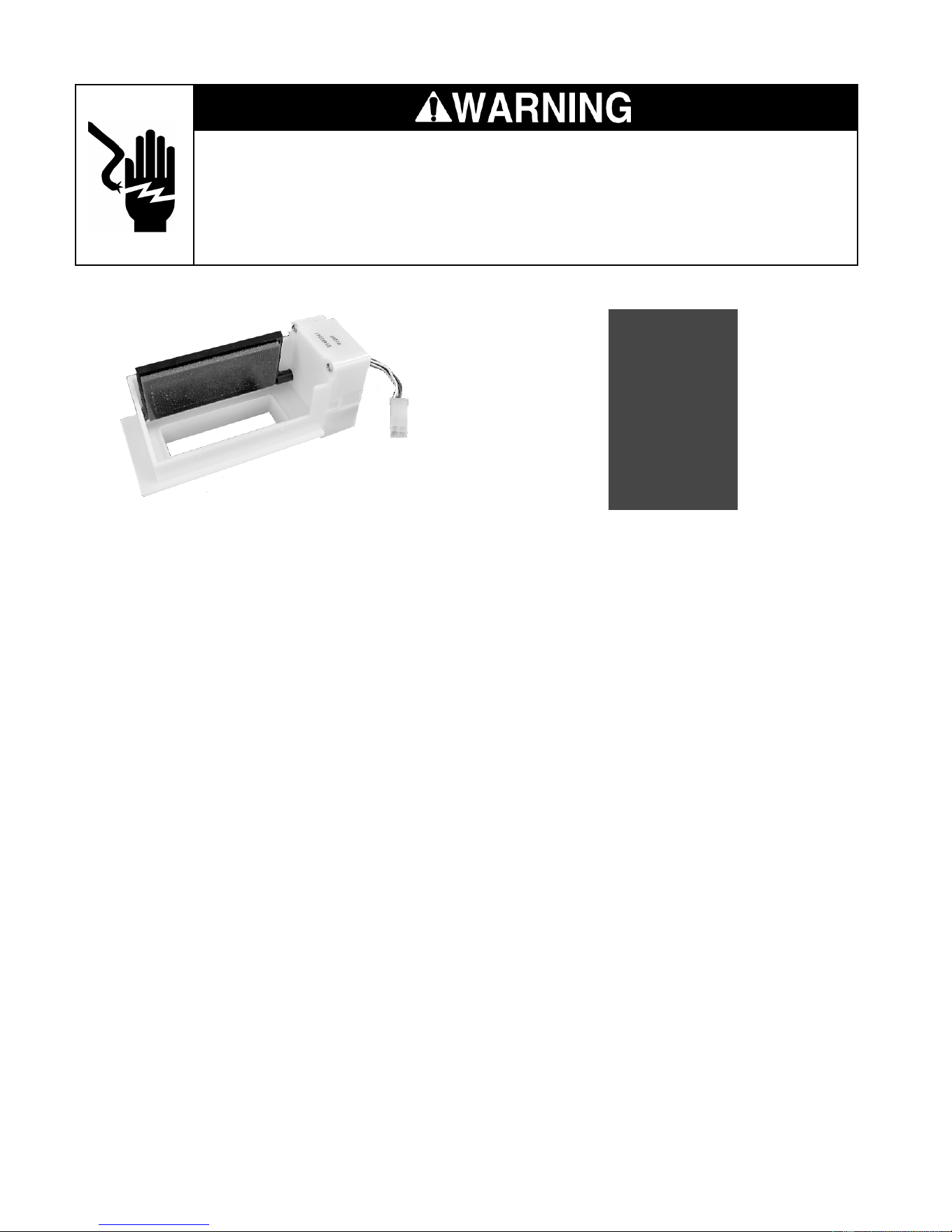
5-4
Electrical Shock Hazard
Disconnect power before servicing.
Replace all panels before operating.
Failure to do so can result in death or electrical shock.
MOTORIZED AIR DOOR
Refer to page 4-14 for the procedure for servic-
ing the motorized air door.
1. Run the diagnostics tests (see page 6-1)
and check for the proper operation of the
air door in step 06.
NOTE: A 12 volts DC square wave is supplied
to the air door in a series of short pulses. It is not
possible to obtain a reliable voltage reading
with a VOM. The remaining steps will allow you
to check the resistance of the air door motor.
2. Unplug the refrigerator or disconnect the
power.
3. Disconnect the motorized air door wire
connector from the main harness.
4. Set the ohmmeter to the R x 10 scale.
5. Touch one of the test probes to the motor-
ized air door connector with the yellow
wire and the other test probe to the white
wire. The meter should indicate approxi-
mately 400 to 450 Ω.
6. Touch one of the test probes to the motor-
ized air door connector with the red wire
and the other test probe to the blue wire.
The meter should indicate approximately
400 to 450 Ω.
DEFROST HEATER & BIMETAL
Refer to page 4-10 for the procedure for servic-
ing the defrost heater and bimetal.
1. Run the diagnostics tests (see page 6-1)
and check for the proper operation of the
defrost heater and bimetal in step 07.
NOTE: If the bimetal is closed, the voltage at
the defrost heater terminals will be 120 volts
AC. The remaining steps will allow you to
check the resistance of the defrost heater and
bimetal.
2. Unplug the refrigerator or disconnect the
power.
3. Disconnect one of the wires going to the
defrost heater.
4. Set the ohmmeter to the R x 1 scale.
5. Touch the ohmmeter test probes to the
defrost heater terminals.
6. The meter should indicate approximately
19 to 27 Ω.
7. Touch the ohmmeter test probes to the
defrost bimetal wire connectors. The meter
should indicate as follows:
• With the bimetal below 20° F, the meter
should indicate continuity (0 Ω).
• With the bimetal above 50° F, the meter
should indicate an open circuit (infinite).
Downloaded from www.ManualsFile.com manuals search engine
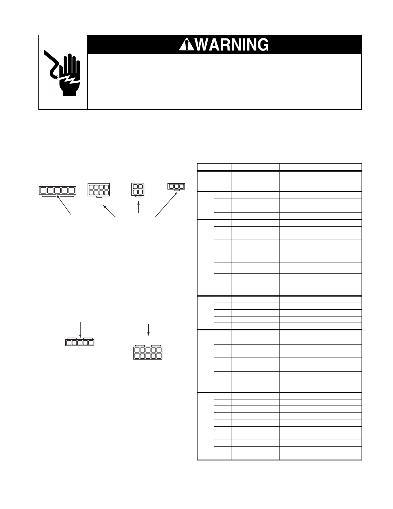
5-5
Electrical Shock Hazard
Disconnect power before servicing.
Replace all panels before operating.
Failure to do so can result in death or electrical shock.
MAIN CONTROL BOARD
INPUTS
P4
THERMISTORS
P3
DISPLAY BOARD
P2
120 VAC SUPPLY
P5
P7
OUTPUTS
P6
OUTPUTS
1
1
2123
123
4
34
5678
2345
1
2
345
1
2
345
109876
Refer to page 4-4 for the procedure for servicing the main control board.
NOTE: See the chart for the main control board test specifications.
PLUG PIN # DESCRIPTION
OUTPUT
CONDITION
1 Communication Line N / A
2 Display Voltage 12 VDC
Measured at pins 2 & 3
3 GND GND
1 Ref. Thermistor GND
2 Frz. Thermistor GND
3 Ref. Thermistor Output 5 VDC
Measured at pins 1 & 3
4 Frz. Thermistor Output 5 VDC Measured at pins 2 & 4
1 Ref. Door Sw Enable 120 VAC
2 Frz. Door Sw Enable 120 VAC
3 N/A
4 Ref. Door Input 120 VAC
Voltage present when door
is o
p
en
5 Ice Maker Valve Input 120 VAC
Voltage present when ice
maker is ener
g
ized
6 Dispenser Valve Input 120 VAC
Voltage present when
dis
p
enser valve is ener
g
ized
7 Bimetal Input 120 VAC
Voltage present when
bimetal is closed
8 Frz. Door Input 120 VAC
1 AC GND AC GND
2 AC L1 120 VAC
3 AC Neutral AC Neutral
4 AC Neutral AC Neutral
5 AC L1 120 VAC
1 Condenser Fan 120 VAC
Voltage present when
condenser fan is on
2 N/A
3 N/A
4 Defrost Heater 120 VAC
Voltage present when
defrost heater is on
5 Ice Maker Enable 120 VAC
Voltage present when I/M
bail arm is down & I/M is
active
1 Air Door
2 Air Door
3 Compressor Drive 3 - 6 VDC
Measured at pins 3 & 8
4 Evap. Fan Feedback N / A
5 Evap. Fan Constant 12 VDC Measured at pins 5 & 9
6 Air Door
7 Air Door
8 Compressor Drive 3 - 6 VDC
Measured at pins 3 & 8
9 Evap. Fan Ground Evap. GND
10 Evap. Fan Run Voltage 5 - 12 VDC Measured at pins 9 & 10
P6
P7
P2
P3
P4
P5
Downloaded from www.ManualsFile.com manuals search engine
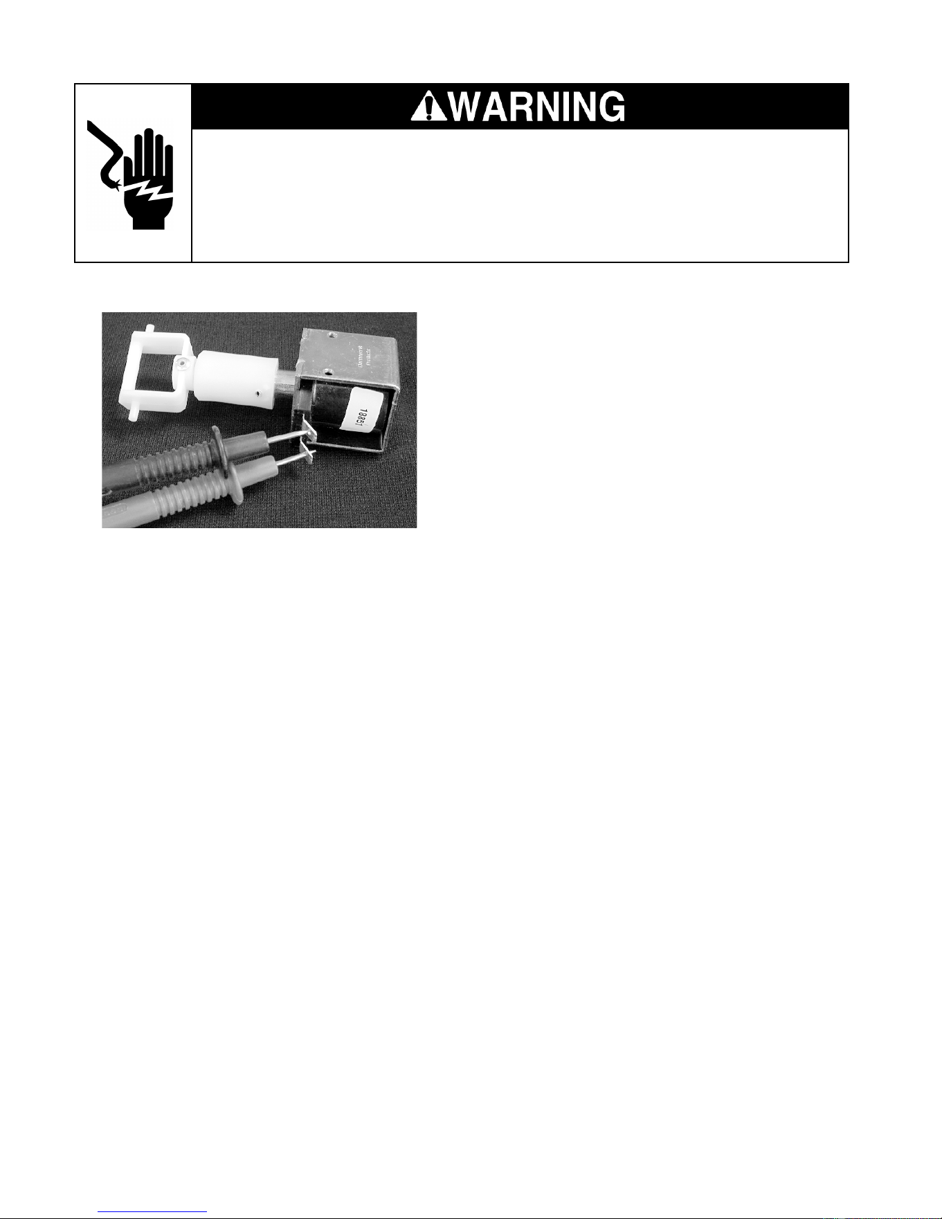
5-6
Electrical Shock Hazard
Disconnect power before servicing.
Replace all panels before operating.
Failure to do so can result in death or electrical shock.
Refer to page 4-16 for the procedure for servic-
ing the crush/cube solenoid.
1. Unplug the refrigerator or disconnect the
power.
2. Disconnect one of the wires going to the
solenoid.
3. Set the ohmmeter to the R x 1 scale.
4. Touch the ohmmeter test probes to the
solenoid terminals.
5. The meter should indicate approximately
35 to 45 ohms.
CRUSH/CUBE SOLENOID
ICE MAKER AUGER MOTOR
Refer to page 4-16 for the procedure for servic-
ing the ice maker auger motor.
1. Unplug the refrigerator or disconnect the
power.
2. Disconnect one of the wires going to the
auger motor.
3. Set the ohmmeter to the R x 1 scale.
4. Touch the ohmmeter test probes to the
auger motor terminals.
5. The meter should indicate approximately
2 to 4 ohms.
Downloaded from www.ManualsFile.com manuals search engine
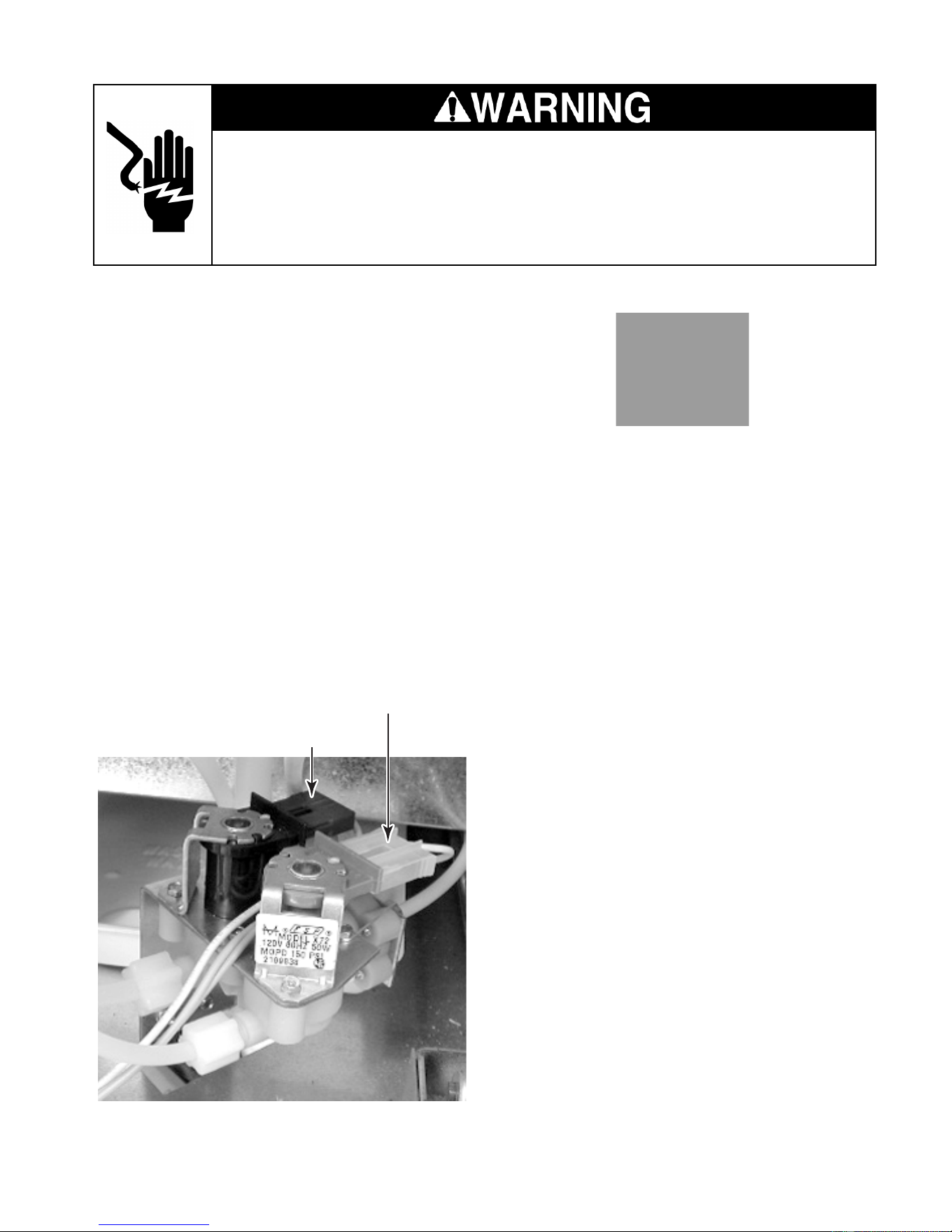
5-7
Electrical Shock Hazard
Disconnect power before servicing.
Replace all panels before operating.
Failure to do so can result in death or electrical shock.
DOOR SWITCH
Refer to page 4-4 for the procedure for servic-
ing a door switch.
1. Unplug the refrigerator or disconnect the
power.
2. Disconnect one of the wires going to the
door switch.
3. Set the ohmmeter to the R x 1 scale.
4. Touch the ohmmeter test probes to the
N.O. and COM door switch terminals.
5. The meter should indicate an open circuit
(infinite).
6. Press the door switch actuator button and
the meter should indicate continuity (0 Ω).
7. Touch the ohmmeter test probes to the
N.C. and COM door switch terminals.
8. The meter should indicate continuity (0 Ω).
NOTE: The door switches are normally-
closed.
9. Press the door switch actuator button and
the meter should indicate an open circuit
(infinite).
WATER VALVE SOLENOID
Refer to page 4-22 for the procedure for servic-
ing the water valve.
1. Unplug the refrigerator or disconnect the
power.
2. Disconnect the wire connectors from the
water valve solenoid terminals.
3. Set the ohmmeter to the R x 1 scale.
4. Touch the ohmmeter test probes to the
terminals of the ice maker solenoid. The
ohmmeter should indicate approximately
160 to 170 Ω.
5. Touch the ohmmeter test probes to the
terminals of the water dispenser solenoid.
The ohmmeter should indicate approxi-
mately 330 to 355 Ω.
Ice Maker Solenoid (1/4″ Outlet)
Water Dispenser Solenoid (5/16″ Outlet)
Downloaded from www.ManualsFile.com manuals search engine

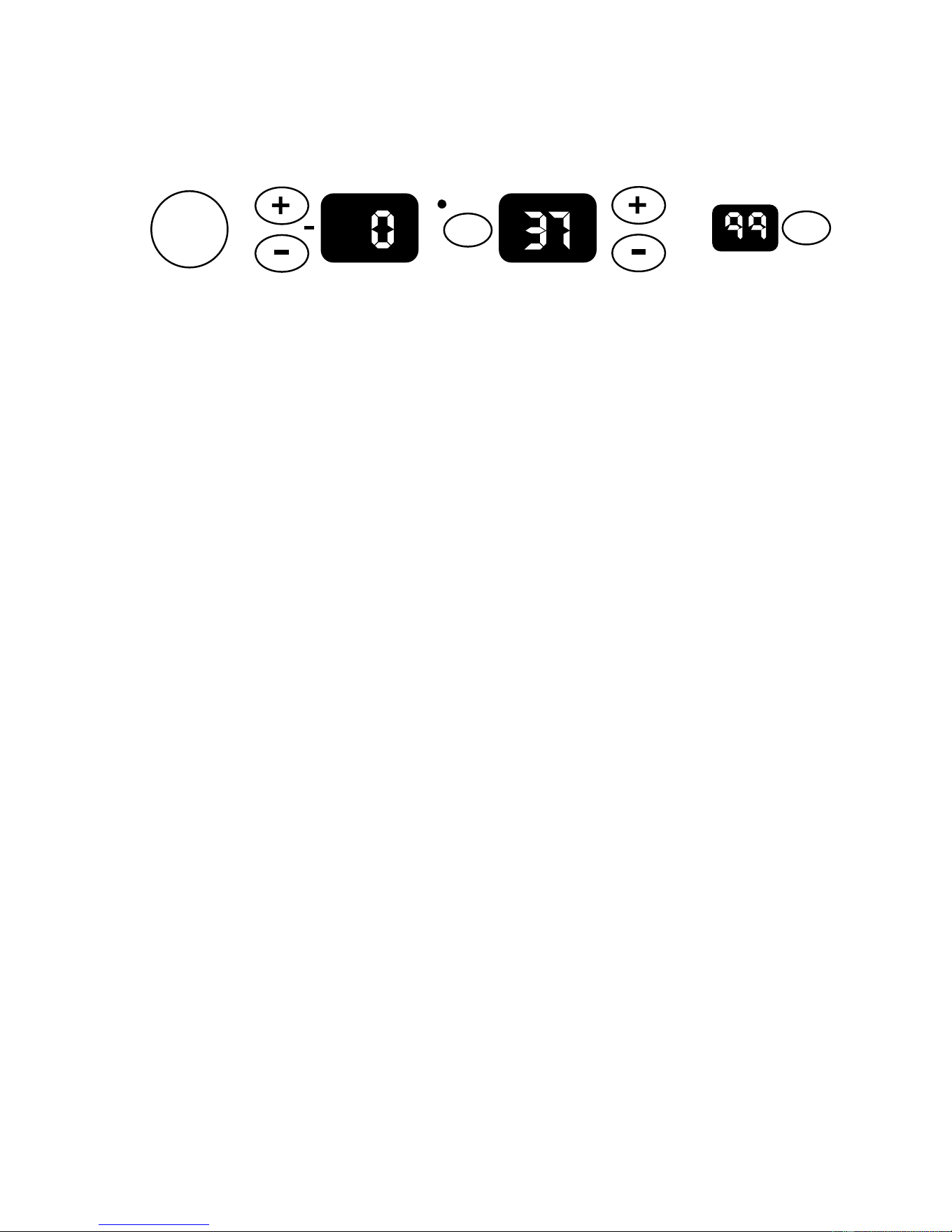
6-1
DIAGNOSIS & TROUBLESHOOTING
DIAGNOSIS
PRE-DIAGNOSTICS CHECKS
• Confirm the refrigerator and freezer tem-
peratures before beginning other checks.
• See if the compressor, evaporator, and
condenser fans are running.
• Check the position of the air door.
DIAGNOSTICS MODE
The Diagnostics Mode is used to:
• Check the refrigerator & freezer ther-
mistors.
• Operate the evaporator fan motor at 3000
rpm.
• Operate the condenser fan motor and com-
pressor.
• Check the defrost bimetal and heater.
To enter the Diagnostics Mode, the control
must be turned on, and be in a normal cooling
mode.
Power
On/Off
Warmer
Colder
Warmer
Colder
FREEZER REFRIGERATOR
WATER FILTER
PERCENT LEFT
RESET
°C
SELECT
Both the Power On/Off and the Water Filter
Reset keys must be functional. The refrigera-
tor display shows the step number. The results
of the checks are displayed on the water filter
status indicator. After 20 minutes, the control
will default from the Diagnostics Mode to a
normal cooling mode.
To enter the diagnostics mode:
• Press and hold the Water Filter Reset
keypad, and then immediately press and
hold the Power keypad. Continue to press
both keypads for 3 seconds, or until you
hear a beep.
To advance the diagnostics sequence:
• To advance to the next step in the se-
quence, press and hold the Water Filter
Reset key for 2 seconds, or until you hear
a beep. The Diagnostics Chart on the next
page shows the step number and the com-
ponent being tested in each step.
Downloaded from www.ManualsFile.com manuals search engine
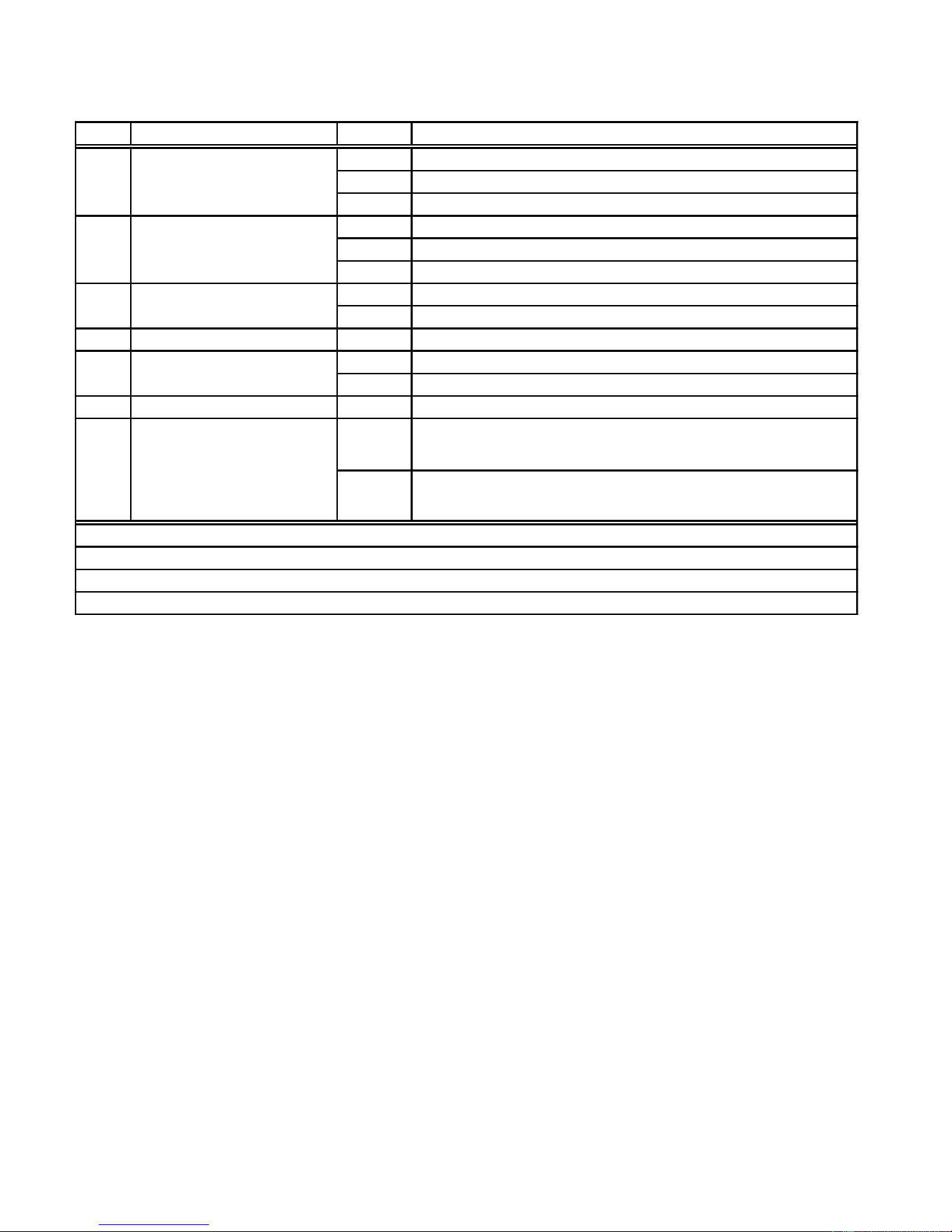
6-2
WATER FILTER INPUT (WFI) TEST
To confirm that the water valves are being
monitored by the WFI control, follow the pro-
cedures listed:
Testing The Dispenser Valve Input
1. Open the refrigerator door.
2. Depress the refrigerator light switch.
3. Place a container under the water spout.
4. Activate the water dispenser.
5. Read the WFI display. “00” indicates a
normal input.
Testing The Ice maker Valve Input
1. Open the refrigerator door.
2. Depress the refrigerator light switch.
3. Activate the ice maker and wait for a water
fill.
4. Read the WFI display during the fill. “99”
indicates a normal input.
DIAGNOSTICS CHART
Step Component Tested Result* Comment
01 Thermistor is within normal range.
02
Thermistor is open or less than –20°F.
03
Thermistor is shorted or greater than 115°F.
01 Thermistor is within normal range.
02
Thermistor is open or less than 10°F.
03
Thermistor is shorted or greater than 115°F.
01 Evaporator Fan Motor is On at correct speed.
02 Evaporator Fan Motor is On at incorrect speed.
0 4 Condenser Fan Motor 01 Condenser Fan Motor is On.
01 Compressor is On at 4500 rpm.
02 Compressor is Off waiting for minimum (7 minute) Off delay.
06 Air Door 01 Air Door fully opens. **
01 Defrost Heater is energized, bimetal closed.
0 2 Bimetal open.
†
FreezerThermistor01
Refrigerator Thermistor02
†
The bimetal may be bypassed with an insulated jumper.
03
05 Compressor
** The air door will close at step 01, and reset to the correct opening after exiting diagnostics.
Press the “Water Filter Reset” to exit diagnostics.
* Shown on the Water Filter Indicator display.
07
Bimetal/Defrost Heater
Evaporator Fan Motor
Downloaded from www.ManualsFile.com manuals search engine
6-3
TROUBLESHOOTING CHART
PROBLEM POSSIBLE CAUSE TEST PROCEDURE-ACTION
No DC control voltage from main
PCB to the inverter board.
See "Component Testing" section for main PCB test procedure.
Control voltage wires loose or
reversed.
Check connections and repair as needed.
Compressor. See "Component Testing" section for compressor/inverter test procedure.
Inverter board. See "Component Testing" section for compressor/inverter test procedure.
Refrigerator control set too
warm.
Set to a lower temperature.
Refrigerator thermistor.
Check wires and connectors. Run diagnostics and if a defective thermistor is
indicated, confirm with ohms test. See "Com
p
onent Testin
g
".
Air door stuck closed or
ino
p
erative.
Look for ice or other blockage in air door. Run diagnostics test to operate air
door.
Evaporator fan motor not
running.
Run diagnostics test to operate the evaporator fan motor. Check for a
blocked fan blade and repair as necessary. Check for 5-17vdc from pin P7-9
to P7-10. If volta
g
e is correct, re
p
lace the motor.
Blocked air flow. Check air door outlet and air returns for blockage.
Warm freezer compartment. See "Freezer compartment too warm."
Refrigerator control set too cold. Set to a higher temperature.
Refrigerator thermistor.
Check wires and connectors. Run diagnostics and if a defective thermistor is
indicated, confirm with ohms test. See "Com
p
onent Testin
g
".
Air door stuck open or
inoperative.
Look for ice or other blockage in air door. Run diagnostics test to operate air
door. Check for proper DC input voltage. If voltage is normal and door will
still not o
p
erate, re
p
lace air door.
Air door seal missing or damaged. Repair or replace seal.
Main PC board. Run diagnostics test to operate air door.
Freezer control set too warm. Set to a lower temperature.
Freezer thermistor.
Check wires and connectors. Run diagnostics and if a defective thermistor is
indicated, confirm with ohms test. See "Com
p
onent Testin
g
".
Evaporator fan motor not
running.
Run diagnostics test to operate the evaporator fan motor. Check for a
blocked fan blade and repair as necessary. Check for 5-17vdc from pin P7-9
to P7-10. If volta
g
e is correct, re
p
lace the motor.
Condenser fan motor not running.
Check for a blocked fan blade and repair as necessary. See "Component
Testin
g
" section for condenser fan motor test
p
rocedure.
Frost blocking evaporator.
Run diagnostics test to operate defrost system. Test defrost heater and bi-
metal.
Freezer control set too cold. Set to a higher temperature.
Refrigerator operating in the
Max Cool or Automatic Max Ice
Mode (see page 3-5).
Normal operation.
Freezer thermistor.
Check wires and connectors. Run diagnostics and if a defective thermistor is
indicated, confirm with ohms test. See "Com
p
onent Testin
g
".
No evaporator fan motor
feedback.
The fan motor will run at 3000 rpm.
Main control board is over
tem
p
erature.
Look for blocked condenser air flow or inoperative condenser fan motor.
Refrigerator over 48°F or
freezer over 15°F for 3 hours.
Run diagnostics and test operation of all components.
Both thermistors failed. Run diagnostics and test thermistors and thermistor leads.
No feedback from evaporator fan
motor.
Run diagnostics and test fan motor and/or wiring.
Refrigerator runs
too long.
Normal.
It is designed for this refrigerator to run almost constantly at the lowest
possible compressor speed. Starting and stopping the compressor uses
more
p
ower than continuous low r
p
m o
p
eration. Instruct customer.
Unit is set for Holiday Mode. Press the Holiday Mode key to cancel operation.
Either door open for over 10
minutes.
Close door and/or check door switches.
No temperature display,
no interior lights.
"Call Service" icon lights
and/or alarm is activated.
Condenser fan runs
but the compressor
will not start.
Freezer
compartment
too warm.
Freezer
compartment
too cold.
Refrigerator
compartment
too cold.
Refrigerator
compartment
too warm.
Downloaded from www.ManualsFile.com manuals search engine

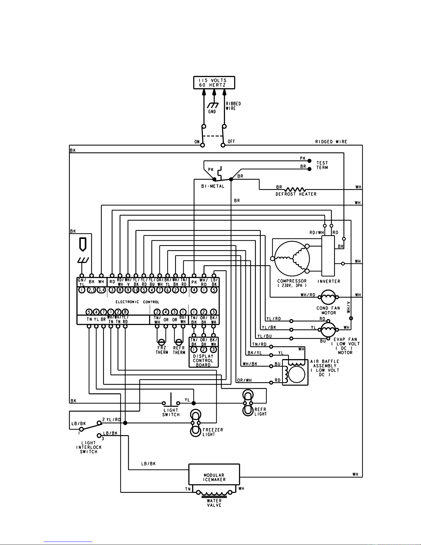
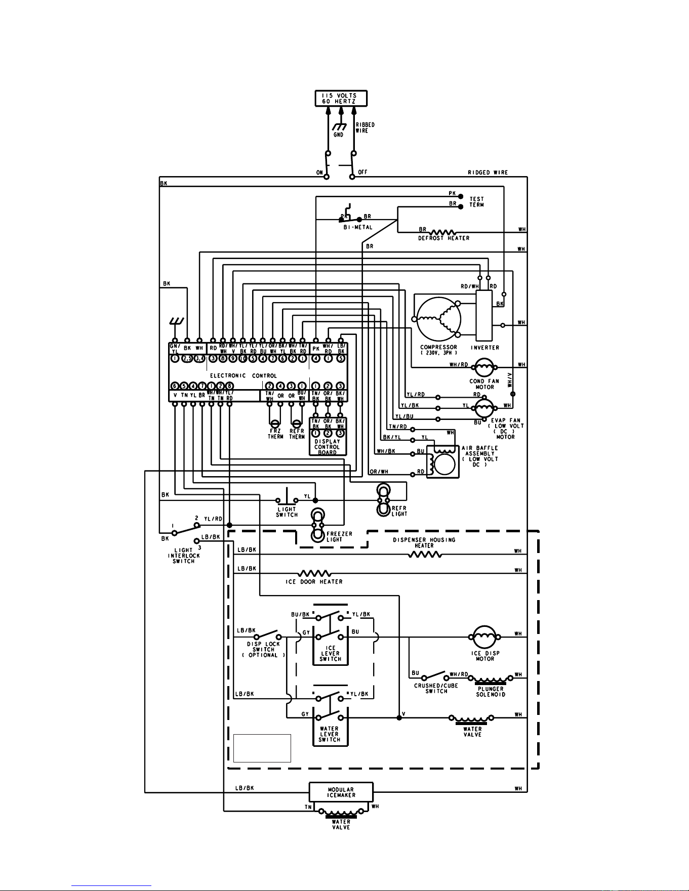
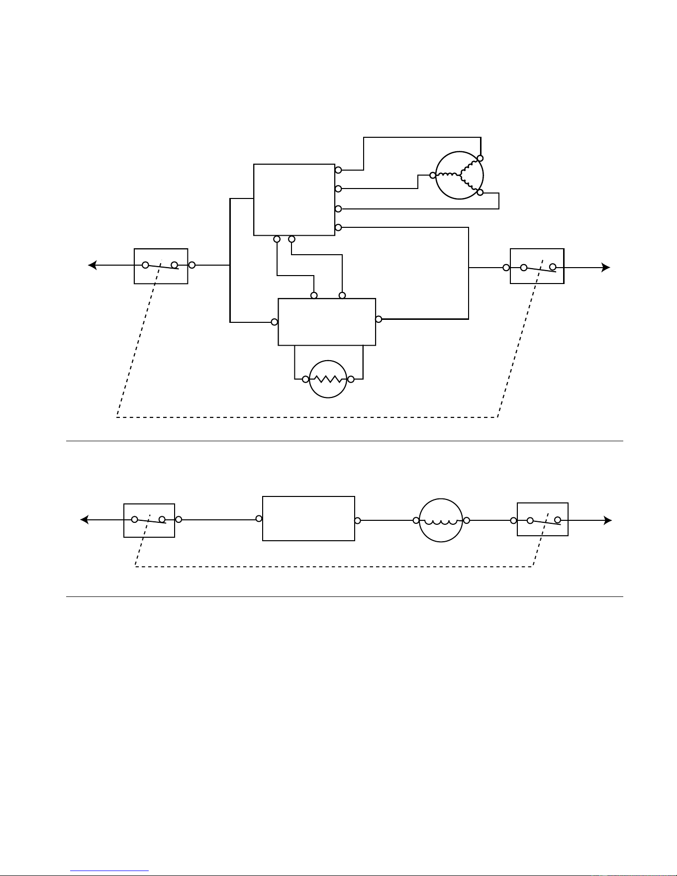
7-3
STRIP CIRCUITS
COOLING CIRCUITS
COMPRESSOR
POWER
ON/OFF
POWER
ON/OFF
WH
RD
RD/WH
BK
COMPRESSOR
L1
N
P7-3P7-8
P5-2
P5-3
INVERTER
BOARD
ELECTRONIC
CONTROL
BOARD
THERMISTOR
CONDENSER FAN MOTOR
POWER
ON/OFF
POWER
ON/OFF
BK
WH/RD
WH
L1
N
P5-2
P6-1
ELECTRONIC
CONTROL
BOARD
CONDENSER
FAN MOTOR
Downloaded from www.ManualsFile.com manuals search engine
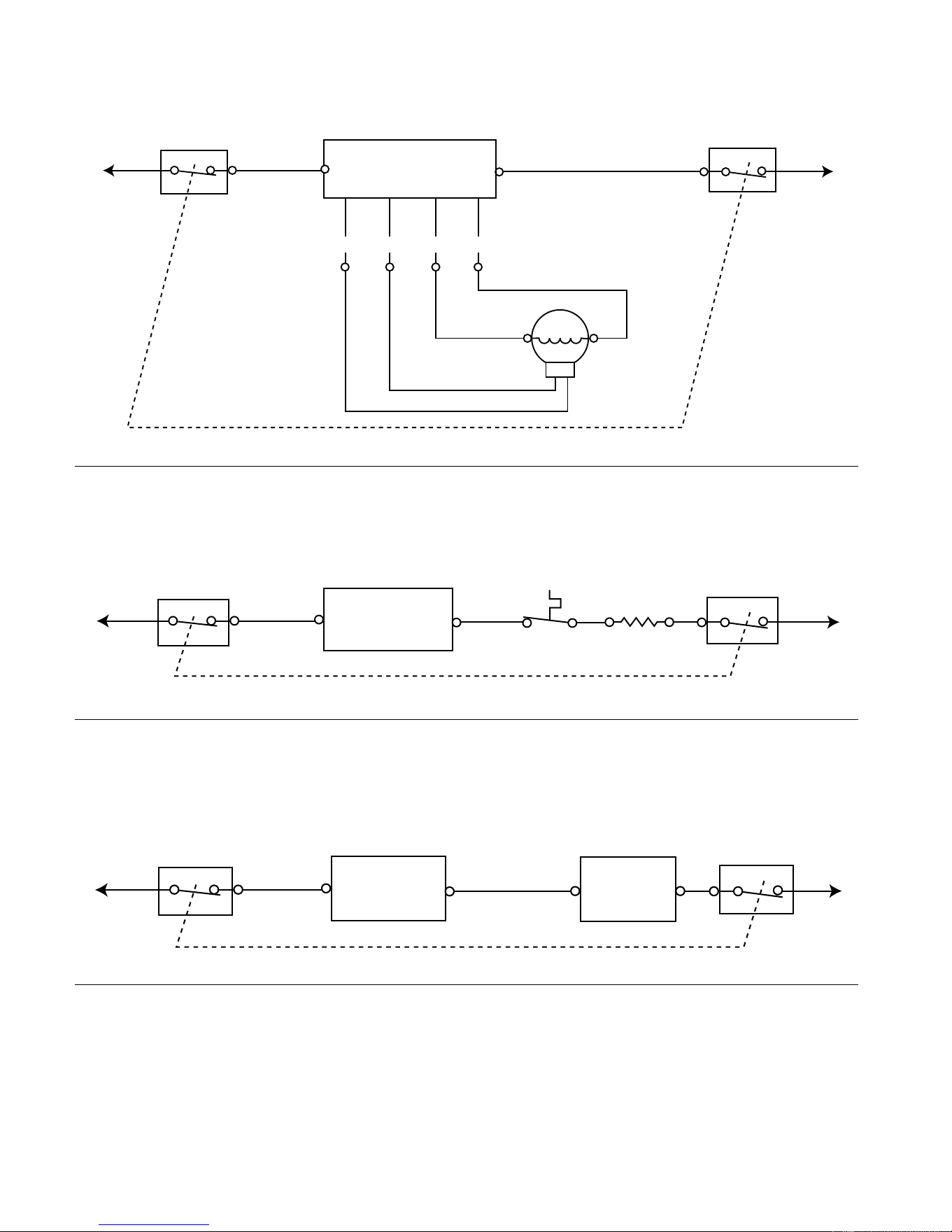
7-4
EVAPORATOR FAN MOTOR
POWER
ON/OFF
POWER
ON/OFF
BK
WH
L1
N
P5-2
P5-3
P7-4 P7-5
P7-9
P7-10
ELECTRONIC CONTROL
BOARD
WH
EVAPORATOR
FAN MOTOR
YL
RD
BU
YL/BU
WH/VT
YL/BK
YL/RD
DEFROST CYCLE
DEFROST HEATER
POWER
ON/OFF
POWER
ON/OFF
BK
DEFROST
HEATER
L1
N
P5-2
P6-4
PK
ELECTRONIC
CONTROL
BOARD
BIMETAL
POWER
ON/OFF
POWER
ON/OFF
BK
L1
N
P5-2
P6-5
LB/BK
WH
ELECTRONIC
CONTROL
BOARD
ICE MAKER
MODULE
ELECTRONIC CONTROL ENABLED CIRCUITS
ICE MAKER
Downloaded from www.ManualsFile.com manuals search engine
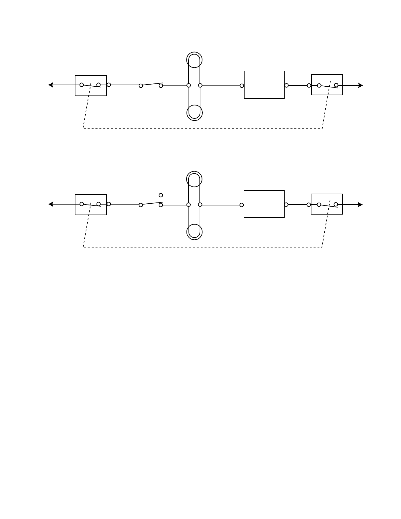


PRODUCT SPECIFICATIONS
AND
WARRANTY INFORMATION SOURCES
IN THE UNITED STATES:
FOR PRODUCT SPECIFICATIONS AND WARRANTY INFORMATION CALL:
FOR TECHNICAL ASSISTANCE WHILE AT THE CUSTOMER’S HOME CALL:
THE TECHNICAL ASSISTANCE LINE: 1-800-253-2870
HAVE YOUR STORE NUMBER READY TO IDENTIFY YOU AS AN
AUTHORIZED SERVICER
FOR LITERATURE ORDERS:
PHONE: 1-800-851-4605
IN CANADA:
FOR PRODUCT SPECIFICATIONS AND WARRANTY INFORMATION CALL:
1-800-461-5681
FOR TECHNICAL ASSISTANCE WHILE AT THE CUSTOMER’S HOME CALL:
THE TECHNICAL ASSISTANCE LINE: 1-800-488-4791
HAVE YOUR STORE NUMBER READY TO IDENTIFY YOU AS AN
AUTHORIZED SERVICER
FOR WHIRLPOOL PRODUCTS: 1-800-253-1301
FOR KITCHENAID PRODUCTS: 1-800-422-1230
FOR ROPER PRODUCTS: 1-800-447-6737
Downloaded from www.ManualsFile.com manuals search engine