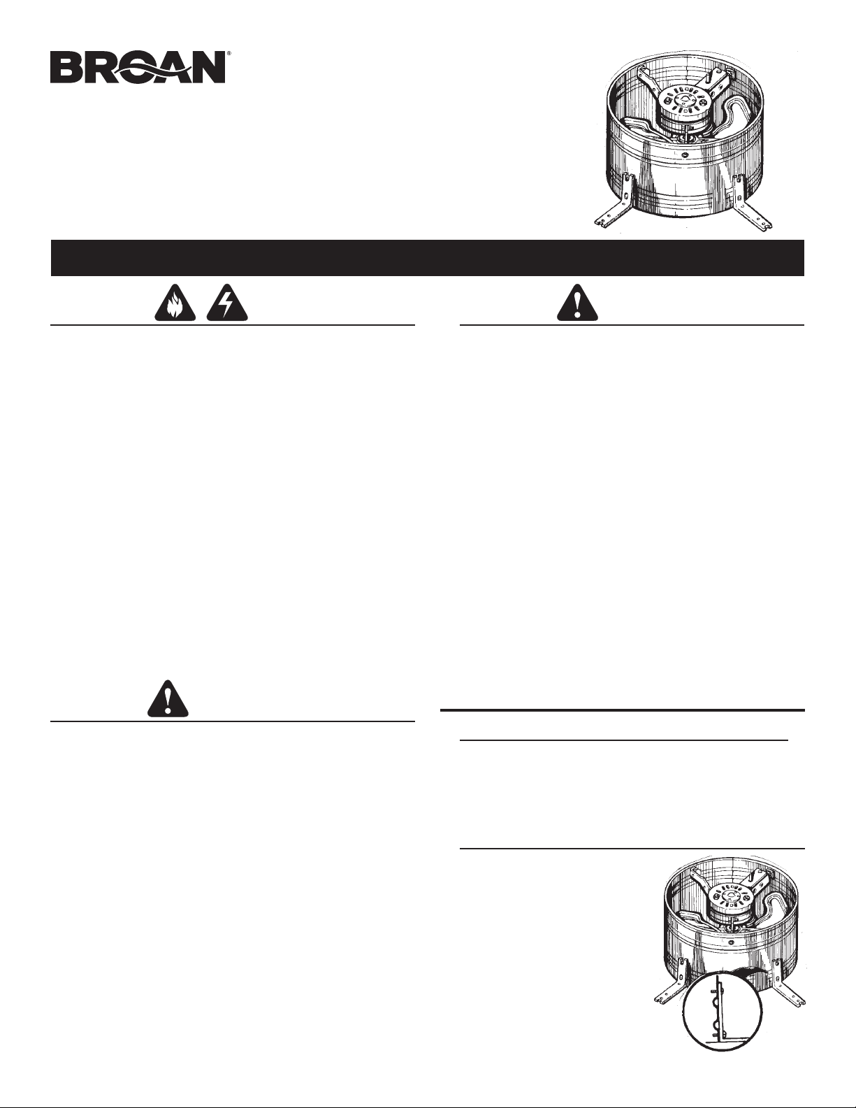
GABLE-MOUNT
POWERED ATTIC
VENTILATOR
MODEL 353
MODEL 35316
READ AND SAVE THESE INSTRUCTIONS
WARNING
TO REDUCE THE RISK OF FIRE, ELECTRIC SHOCK, OR INJURY TO
PERSONS, OBSERVE THE FOLLOWING:
1. Use this unit only in the manner intended by the manufacturer. If you have
questions, contact the manufacturer at the address or telephone number
listed in the warranty.
2. Before servicing or cleaning unit, switch power off at service panel and lock
the service disconnecting means to prevent power from being switched
on accidentally. When the service disconnecting means cannot be locked,
securely fasten a prominent warning device, such as a tag, to the service
panel.
3. Installation work and electrical wiring must be done by a qualified person(s)
in accordance with all applicable codes and standards, including fire-rated
construction codes and standards.
4. Sufficient air is needed for proper combustion and exhausting of
gases through the flue (chimney) of fuel burning equipment to prevent
backdrafting. Follow the heating equipment manufacturer’s guidelines and
safety standards such as those published by the National Fire Protection
Association (NFPA), and the American Society for Heating, Refrigeration
and Air Conditioning Engineers (ASHRAE), and the local code authorities.
5. When cutting or drilling into wall or ceiling, do not damage electrical wiring
and other hidden utilities.
6. The wiring must be permanent. DO NOT USE AN EXTENSION CORD!
Use 14 GA. MINIMUM copper wire. Although the Powered Attic Ventilator
may be wired directly to power, we advise that some type of shut off
switch be installed in the line. Please see the section on electrical wiring
for suggested wiring diagrams and instructions.
7. This unit must be grounded.
7. Records show, under ideal conditions, exposed galvanized steel can
remain rust free up to 100 years. For best protection, the exposed
portion of the roof sheet should be painted, especially in areas of
unusually high industrial air pollution. Follow paint manufacturer’s
instructions for good adhesion.
8. This ventilator is intended for Gable installation. The Broan Models
350, 355, 356 & 358 Roof Mount Ventilators are available for roof
mount applications.
9. Please read specification label on product for further information
and requirements.
10. The wearing of safety glasses and gloves is recommended when
installing, maintaining or cleaning the unit to reduce the risk of injury
that could be caused by the presence of thin metal and/or high
moving parts.
11. If the fan makes excessive noise or if there is unusual noise or smells
of smoke, disconnect power supply and contact customer service.
If this fan is to be used to ventilate a garage:
A. Use only in single family, residential garages
B. Install in a GFCI protected branch circuit
C. To help offset the risk posed by high concentrations of vapors from
paints, glues, solvents, and fuels, install fan at least 18 inches (0.5m)
above the floor
D. NEVER run a vehicle or use a fuel burning appliance inside of a
garage. Deadly levels of carbon monoxide can build up in the area.
Using this garage fan, or opening windows and doors, will NOT
supply enough fresh air to eliminate the danger.
E. Run regularly if exposed to salty air environments
F. Extra cleaning may be required due to possible dirty surroundings
Screwdrivers (Slotted & Phillips)
Hammer
Ruler
Pencil
TOOLS & MATERIALS REQUIRED
PREPARE THE VENTILATOR
1. Unpack the ventilator and find:
1 - power unit with wiring box
4 - angle brackets
8 - sheet metal screws
2. Fasten the four (4) angle
mounting brackets to the housing
using the eight (8) sheet metal
screws provided. Position the
bracket flush with the edge of the
housing band. A close fit between
ventilator and louver will minimize
air recirculation.
CAUTION
1. For general ventilating use only. Do not use to exhaust hazardous or
explosive materials or vapors.
2. To avoid motor bearing damage and noisy and/or unbalanced impellers,
keep drywall spray, construction dust, etc. off power unit.
CAUTION
Electrical supplies
(to comply with codes)
Nails
3. This unit has an unguarded impeller. Do not use in locations readily
accessible to people or animals.
4. Fan is equipped with a thermostat which may start fan automatically.
To reduce risk of injury or electric shock while servicing and cleaning
unit, switch power off at service panel and lock service panel to
prevent power from being switched on accidentally. When the service
disconnecting means cannot be locked, securely fasten a prominent
warning device, such as a tag, to the service panel.
5. Home Ventilating Institute (HVI) recommends one square foot of
open air inlet per 300 cfm of fan capacity. The best location for these
air intake vents are under the eaves with direct access to the attic.
Vents for attic side wall installations should be placed at the end of
the house opposite the installed ventilator. Failure to provide these
intakes could cause natural-draft gas appliances to backdraft.
6. Your attic installation will create a screened opening into your attic
space. During a heavy rainstorm there could be a light spray of rain
into this attic space. This is a normal condition with all attic ventilators
and will not cause any damage to the structure.We recommend that
you do not store any valuable articles directly under the fan opening
in the gable. During extreme rain and wind storms you may want to
turn on your attic ventilator to prevent excess mositure accumulaltion
in your attic.
2
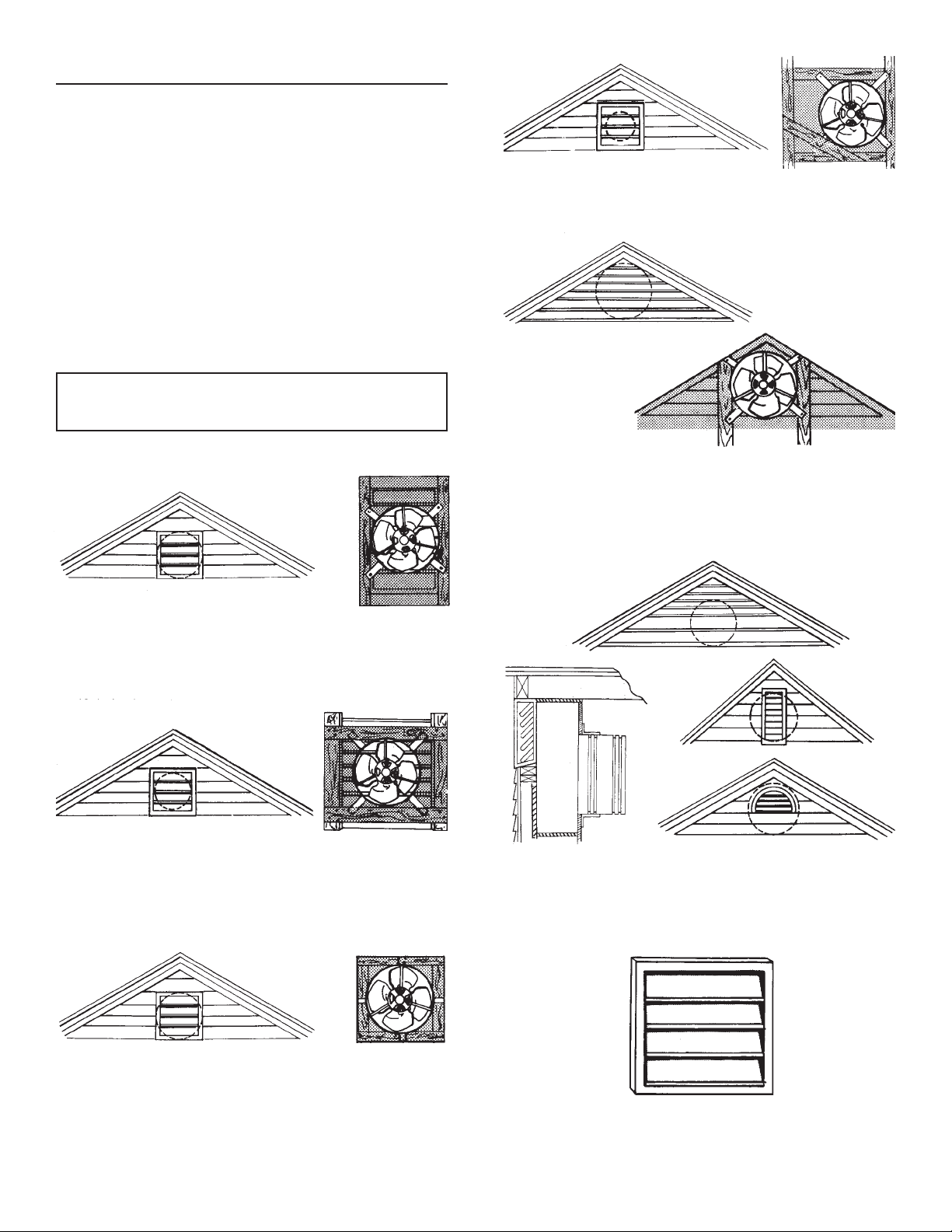
INSTALL THE VENTILATOR
1. The ventilator is designed to mount behind existing louvers.
Find the type of louver you have in the examples below. If no
louver exists, one must be installed. Louver should be mounted
in the center of the upper portion of the gable as high as pos-
sible. For maximum efficiency, the area of the louver should
be greater than the outlet area of the ventilator.
There is some loss in fan output because the louver blocks
some of the air flow. Metal louvers have more open area than
wood louvers and usually allow more air flow.
When installing the ventilator behind louvers, you should seal
off any louver area not covered by the ventilator housing band
to prevent air leakage and recirculation. We suggest you mount
the ventilator on a piece of plywood for best sealing. Allow at
least one square foot of air intake area for every 300 CFM of
ventilator capacity.
CAUTION! When installing louvers or shutters, do not re-
move any existing structural members without providing
alternate support members.
The ventilator can be mounted flush to a rectangular type
louver by fastening through the mounting brackets to the
frame of the louver.
On a wide louver the brackets can first be fastened to the
backside of two boards of the appropriate length and these
boards can then be fastened to the frame.
With a narrow louver mounted between studs on 16” centers,
two of the brackets can first be mounted to the backside of
boards and the boards and other brackets nailed to the studs.
The ventilator can also be mounted off-center in an odd
shaped louver.
On large triangular louvers, mount to the frame or nail boards
to the frame to provide a mounting surface for the ventilator.
For the most effective installation, enclose the louver area not
covered by the fan, with plywood or similar material.
Louvers that are smaller than the ventilator outlet will restrict
air delivery. When this condition exists, a chamber should be
built to properly direct the air through the louvers. A typical
example of the suggested construction is shown.
An automatic shutter, Model 433, may also be installed to
provide the necessary outlet for the fan. Installation instruc-
tions are provided with the Model 433 shutter.

WIRE THE VENTILATOR
1. Remove the thermostat wiring box cover plate. Bring the power
cable at least 6” into the thermostat wiring box. Fasten to box
with appropriate connector.
2. For standard installation, connect the two leads in the ther-
mostat wiring box to the two power leads. Attach ground wire
from the power cable to the green screw in the box.
TO
MOTOR
GROUND TO
SWITCH
BOX
WHITE
BLACK
THERMOSTAT
WHITE
MASTER
ON-OFF SWITCH
120 VOLTS
LINE IN
MOTOR
VENTILATOR
WIRING BOX
MASTER
ON-OFF
SWITCH
BLK
GRD
WHT
This diagram shows how to by-pass the thermostat to turn the
ventilator on or off manually.
BLACK
BLK
GRD
WHT
TO
MOTOR
BLACK
THERMOSTAT
WHITE
RED
GROUND TO
SWITCH
BOX
WHITE
120 VOLTS
LINE IN
BLACK
RED
THERMOSTAT BY-PASS SWITCH
(SHOULD NORMALLY BE IN “OFF” POSITION)
MASTER
ON-OFF SWITCH
MOTOR
VENTILATOR
WIRING BOX
MASTER
ON-OFF
SWITCH
BLK
GRD
WHT
BLK
GRD
WHT
THERMOSTAT
BY-PASS
SWITCH
RED
TO
MOTOR
BLACK
THERMOSTAT
WHITE
RED
WHITE
120 VOLTS
LINE IN
RED
THERMOSTAT BY-PASS SWITCH
(SHOULD NORMALLY BE IN “OFF” POSITION)
MASTER
ON-OFF SWITCH
MOTOR
VENTILATOR
WIRING BOX
MASTER
ON-OFF
SWITCH
BLK
GRD
WHT
BLK
GRD
WHT
THERMOSTAT
BY-PASS
SWITCH
RED
BLACK
This diagram shows how to wire a humidistat.
3. Replace the metal cover plate over the thermostat wiring box
and fasten securely.
4. The thermostat setting determines the temperature at which
the ventilator turns “on”. The ventilator automatically turns off
when the attic temperature is 10
O
F lower than the thermostat.
If you want the ventilator to operate at a different temperature,
insert a screwdriver into the slot and turn the indicator to the
desired temperature.
The ventilator will now turn “ON” at this temperature and “OFF”
10
O
F lower.
70
O
F
80
O
F
90
O
F
100
O
F
110
O
F
120
O
F
130
O
F
FAN ON
TEMPERATURE
Indicator shown rotated fully counterclockwise for a setting
of 70
O
F.
3
HUMIDISTAT
TO
HUMIDISTAT
BLACK
GROUND TO
SWITCH BOX
WHITE
BLACK
BLACK
GROUND TO
SWITCH BOX
WHITE
BLACK
BLACK
BLACK
GROUND TO
SWITCH BOX
WHITE
GROUND TO
SWITCH BOX

99045045B
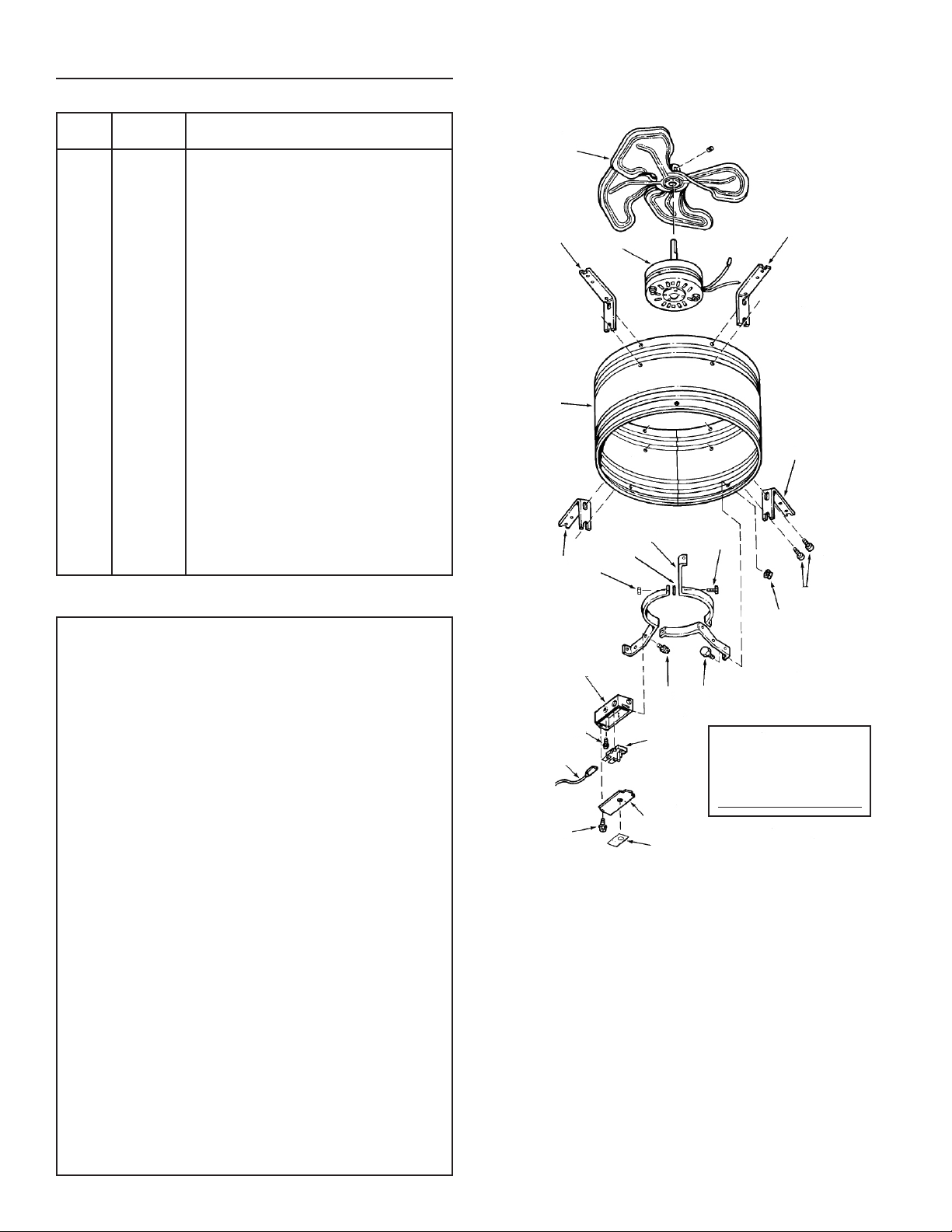
SERVICE PARTS
Models 353 & 35316
KEY PART
NO. NUMBER DESCRIPTION
1 97006971 Fan Blade w/Set Screw
2 97009316 Motor-353
97015764 Motor with Capacitor-35316
3 98005039 Housing Mounting Brackets (4 Required)
4 98006879 Housing Band Assembly
5 93150458 #10B-16 x 3/8 Sheet Metal Screw*
(8 Required)
6 98008298 Motor Mount Band (3 Required)
7 99170254 Screw, 5/16-18 x 3/4 Hex Head
Machine Screw* (3 Required)
8 99260465 Nut, 5/16-18 Hex* (3 Required)
9 99200202 Screw, 1/4 -20 x 1/2 Hex Head* (3 Required)
10 99260477 Whiz Locknut, 1/4-20 Hex* (3 Required)
11 99170245 #8B-18 x 3/8 Sheet Metal Screw* (3 Req.)
12 98009757 Wiring Box
13 99150471 Green Ground Screw #10-32 x 1/2 Hex
Washer Head*
14 99030144 AdjustableThermostat
15 97005329 Lead Wire Assembly
16 98006877 Wiring Box Cover
17 990717246 Label-35316
990726384 Label-353
**18 99250948 Washer* (3 Required)
*Standard Hardware. May be purchased locally.
**May be removed when serviced.
BROAN-NUTONE ONE YEAR LIMITED WARRANTY
Broan-NuTone warrants to the original consumer purchaser of its
products that such products will be free from defects in materials or
workmanship for a period of one year from the date of original purchase.
THERE ARE NO OTHER WARRANTIES, EXPRESS OR IMPLIED,
INCLUDING, BUT NOT LIMITED TO, IMPLIED WARRANTIES OF
MERCHANTABILITY OR FITNESS FOR A PARTICULAR PURPOSE.
During this one-year period, Broan-NuTone will, at its option, repair
or replace, without charge, any product or part which is found to be
defective under normal use and service.
THIS WARRANTY DOES NOT EXTEND TO FLUORESCENT LAMP
STARTERS, TUBES, HALOGEN AND INCANDESCENT BULBS,
FUSES, FILTERS, DUCTS, ROOF CAPS, WALL CAPS AND OTHER
ACCESSORIES FOR DUCTING. This warranty does not cover
(a) normal maintenance and service or (b) any products or parts
which have been subject to misuse, negligence, accident, improper
maintenance or repair (other than by Broan-NuTone), faulty installation
or installation contrary to recommended installation instructions.
The duration of any implied warranty is limited to the one-year
period as specified for the express warranty. Some states do not
allow limitation on how long an implied warranty lasts, so the above
limitation may not apply to you.
BROAN-NUTONE’S OBLIGATION TO REPAIR OR REPLACE, AT
BROAN-NUTONE’S OPTION, SHALL BE THE PURCHASER’S
SOLE AND EXCLUSIVE REMEDY UNDER THIS WARRANTY.
BROAN-NUTONE SHALL NOT BE LIABLE FOR INCIDENTAL,
CONSEQUENTIAL OR SPECIAL DAMAGES ARISING OUT OF
OR IN CONNECTION WITH PRODUCT USE OR PERFORMANCE.
Some states do not allow the exclusion or limitation of incidental or
consequential damages, so the above limitation or exclusion may not
apply to you.
This warranty gives you specific legal rights, and you may also have
other rights, which vary from state to state. This warranty supersedes
all prior warranties.
To qualify for warranty service, you must (a) notify Broan-NuTone at
the address or telephone number below, (b) give the model number
and part identification and (c) describe the nature of any defect in the
product or part. At the time of requesting warranty service, you must
present evidence of the original purchase date.
Broan-NuTone LLC, 926 W. State Street,
Hartford, Wisconsin 53027 www.broan-nutone.com 800-558-1711
1
2
3
4
3
8
18
6
7
9
11
10
5
3
3
12
13
14
15
11
17
16
Replacement parts
can now be ordered
on our website.
Please visit us at
www.broan-nutone.com
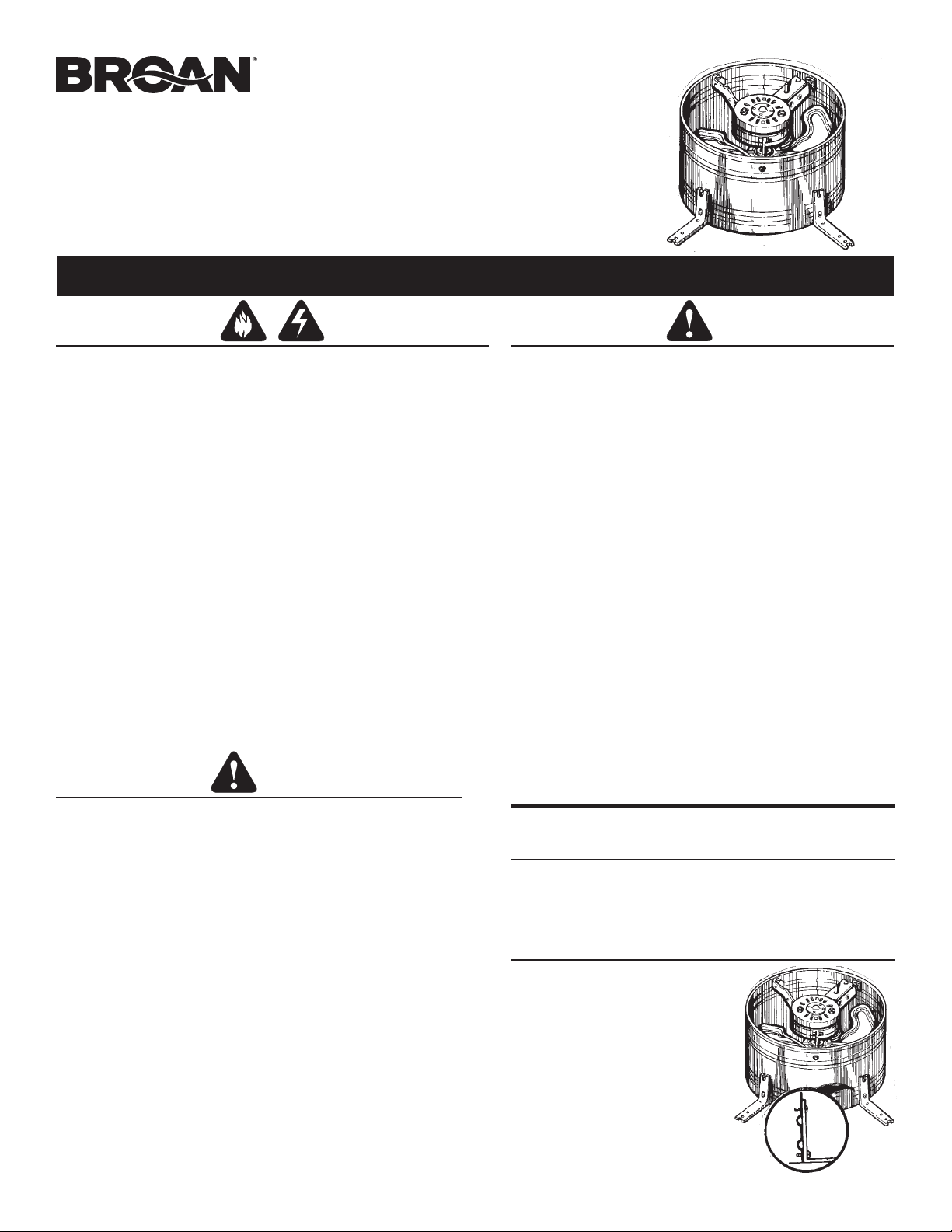
VENTILADOR
ELÉCTRICO PARA
ÁTICO MONTADO
EN HASTIAL
MODELO 353
MODELO 35316
LEA Y CONSERVE ESTAS INSTRUCCIONES
ADVERTENCIA
PARA REDUCIR EL RIESGO DE INCENDIOS, DESCARGAS ELÉCTRICAS O LESIONES
PERSONALES, OBSERVE LAS SIGUIENTES PRECAUCIONES:
1. Use la unidad solo de la manera indicada por el fabricante. Si tiene preguntas,
comuníquese con el fabricante a la dirección o al número telefónico que se incluye
en la garantía.
2. Antes de dar servicio a la unidad o de limpiarla, interrumpa el suministro eléctrico
en el panel de servicio y bloquee los medios de desconexión del servicio para evitar
que la electricidad se reanude accidentalmente. Cuando no sea posible bloquear los
medios de desconexión del servicio, fije firmemente una señal de advertencia (como
una etiqueta) en un lugar visible del panel de servicio.
3. El trabajo de instalación y el cableado eléctrico deben estar a cargo de un personal
capacitado, de acuerdo con todos los códigos y normas correspondientes, incluidos
los códigos y normas de construcción específicos sobre protección contra incendios.
4. Es necesario suficiente aire para que se lleve a cabo una combustión y una extracción
adecuadas de los gases a través del tubo de humos (chimenea) del equipo quemador
de combustible, con el fin de evitar el contratiro. Siga las directrices y las normas de
seguridad del fabricante del equipo de calentamiento, como aquellas publicadas
por la Asociación Nacional de Protección contra Incendios (National Fire Protection
Association, NFPA), y la Sociedad Americana de Ingenieros en Calefacción,
Refrigeración y Aire Acondicionado (American Society for Heating, Refrigeration and
Air Conditioning Engineers, ASHRAE), y las autoridades de los códigos locales.
5. Al cortar o perforar a través de la pared o del techo, tenga cuidado de no dañar el
cableado eléctrico ni otros servicios ocultos.
6. El cableado debe ser permanente. ¡NO UTILICE UNA EXTENSIÓN ELÉCTRICA!
Utilice cable de cobre MÍNIMO de calibre 14. Aunque el ventilador eléctrico para ático
puede cablearse directo a la electricidad, le aconsejamos que instale en la línea
algún tipo de interruptor de apagado. Vea los diagramas de cableado e instrucciones
sugeridas en la sección del cableado eléctrico.
7. Esta unidad debe estar conectada a tierra.
7. Los registros muestran que, bajo condiciones ideales, el acero galvanizado
expuesto puede mantenerse libre de corrosión hasta por 100 años. Para
tener la mejor protección, la parte expuesta de la hoja del techo debe
pintarse, en especial en áreas con una contaminación del aire por ambiente
industrial que sea inusualmente alta. Siga las instrucciones del fabricante
de la pintura para tener buena adhesión.
8. Este ventilador está diseñado para instalarse en un hastial. Los ventiladores
para montaje en el techo Broan modelos 350, 355, 356 y 358 están
disponibles para aplicaciones de montaje en el techo.
9. Lea la etiqueta de especificaciones del producto para ver información y
requisitos adicionales.
10. Se aconseja llevar guantes y gafas de protección durante la instalación, el
mantenimiento o la limpieza del aparato para reducir el riesgo de lesiones
causadas por la presencia de metal delgado y/o de piezas móviles en
altura.
11.
Si el ventilador emite un ruido excesivo o si se observan sonidos
anormales
o un olor a humo, desconectar la fuente de alimentación y póngase en
contacto con el servicio al cliente.
Si se utiliza este ventilador para ventilar un garaje :
A. Utilizarlo solamente en el garaje de una casa unifamiliar
B. Instalar en un circuito protegido por un GFCI (interruptor accionado por pérdida
de conexión a tierra)
C. Para contribuir a reducir los riesgos impuestos por altas concentraciones
de vapor de pintura, de cola, de disolventes y de combustibles, instalar el
ventilador al menos a 0,5 m (18 pulgadas) del suelo
D. NUNCA dejar en funcionamiento el motor de un coche en un garaje. NUNCA
usar un aparato de combustión en un garaje. El monóxido de carbono podría
alcanzar un nivel peligroso, incluso mortal. El uso de este ventilador de garaje
o la apertura de puertas y ventanas no permitirán un suministro suficiente de
aire fresco para eliminar el peligro.
E. Activar periódicamente cuando el medio ambiente es salino
F. Una limpieza con mayor frecuencia podría ser necesaria debido al medio
ambiente potencialmente sucio
Destornilladores
(plano y Phillips)
Martillo
Regla
HERRAMIENTAS Y MATERIALES
REQUERIDOS
PREPARE EL VENTILADOR
PRECAUCIÓN
1. Solo para usarse como medio de ventilación general. No debe usarse para la
extracción de materiales o vapores peligrosos o explosivos.
2. Para evitar daños a los cojinetes del motor y rotores ruidosos o desbalanceados,
mantenga la unidad de potencia protegida contra rociados de yeso, polvos de
construcción, etc.
3. Esta unidad tiene un impulsor sin protección. No lo use en sitios fácilmente accesibles
para personas o animales.
4. El ventilador está equipado con un termostato que puede encender automáticamente
el ventilador. Para reducir el riesgo de incendio o de descarga eléctrica al dar servicio
y limpiar la unidad, interrumpa el suministro eléctrico en el panel de servicio y bloquee
el panel de servicio para evitar que se active accidentalmente la electricidad. Cuando
no sea posible bloquear los medios de desconexión del servicio, fije firmemente una
señal de advertencia (como una etiqueta) en un lugar visible del panel de servicio.
5. El Instituto de Ventilación de la Vivienda (Home Ventilation Institute, HVI) recomienda
un pie cuadrado de entrada de aire abierto por 300 pies
3
/min (8.5 m
3
/min) de
capacidad del ventilador. La mejor ubicación para estas ventilaciones de admisión
de aire es debajo de los aleros con acceso directo al ático. Las ventilaciones para
instalaciones en paredes laterales de áticos deben colocarse al extremo de la
vivienda, al lado opuesto del ventilador instalado. De no suministrar estas entradas
se podría ocasionar que se invierta la corriente natural de los electrodomésticos de
gas.
6. La instalación en el ático creará una abertura con malla hacia el espacio
de su ático. Si hubiera una lluvia muy intensa podría provocarse un ligero
rociado de la lluvia en este espacio del ático. Esta situación es normal
con todos los ventiladores de ático y no provocará daños a la estructura.
Le recomendamos que no guarde artículos de valor directamente debajo de la
abertura del ventilador en el hastial. Durante lluvia y viento extremos, tal vez quiera
encender el ventilador para ático para prevenir que se acumule un exceso de
humedad en su ático.
PRECAUCIÓN
2. Sujete los cuatro (4) soportes para
montaje en ángulo a la vivienda
utilizando los ocho (8) tornillos
autorroscantes suministrados.
Coloque el soporte al ras del borde
de la banda de la vivienda. Un
ajuste preciso entre el ventilador
y el alistonado minimizará la
recirculación de aire.
Lápiz
Suministros eléctricos
(para cumplir con los códigos)
Clavos
1. Desempaque el ventilador y encuentre:
1 - unidad eléctrica con caja
de conexiones
4 - soportes en ángulo
8 - tornillos autorroscantes
2
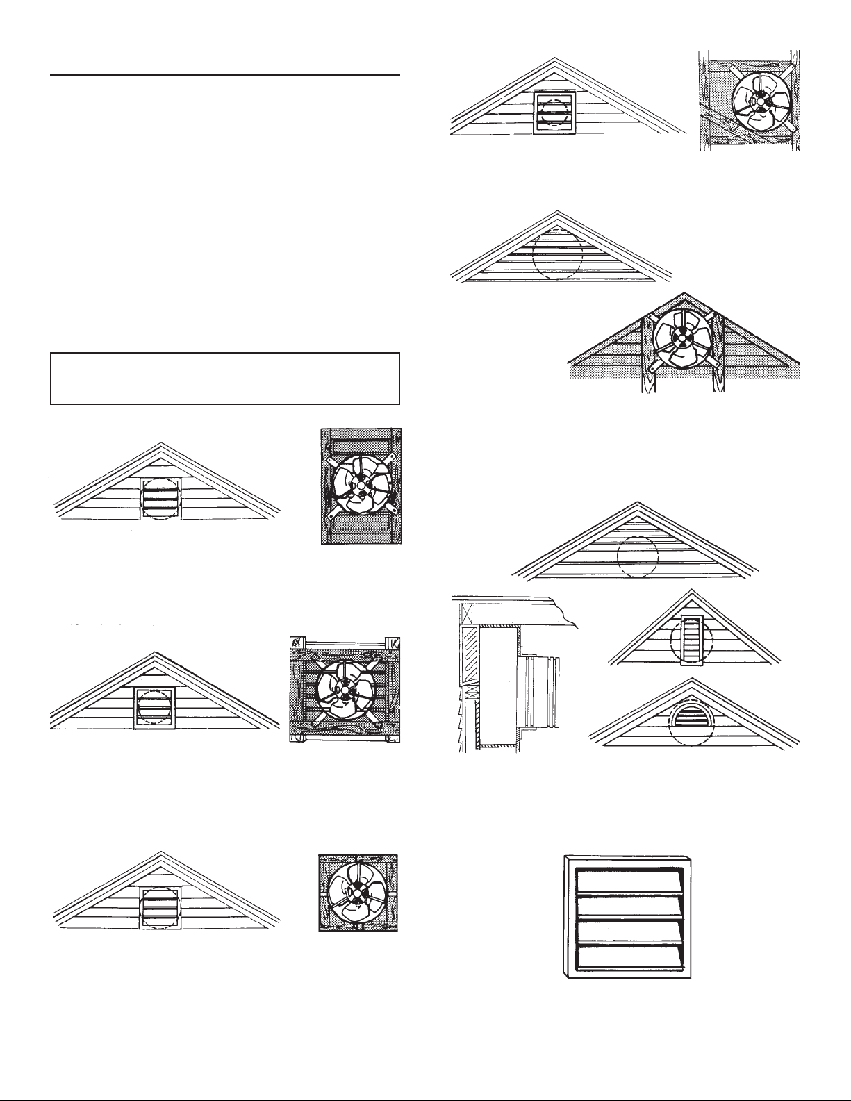
INSTALE EL VENTILADOR
1. El ventilador está diseñado para montarse detrás del
alistonado existente. Encuentre el tipo de alistonado que
tiene en los ejemplos siguientes. Si no hay alistonado, debe
instalar uno. El alistonado debe montarse al centro de la parte
superior del hastial, tan alto como sea posible. Para obtener
la máxima eficiencia, el área del alistonado debe ser mayor
que el área de salida del ventilador.
Existe algo de pérdida en la salida del ventilador, porque el
alistonado bloquea parte del flujo de aire. Los alistonados
metálicos tienen más superficie abierta que los de madera,
y por lo general permiten más flujo de aire.
Cuando instale el ventilador detrás del alistonado, debe sellar
toda superficie de alistonado no cubierta por la banda de la
cubierta del ventilador, para prevenir fugas y recirculación de
aire. Le sugerimos que monte el ventilador en una pieza de
madera contrachapada para obtener el mejor sellado. Permita
por lo menos un pie cuadrado de superficie de entrada de
aire por cada 300 pies
3
/min (8.5 m
3
/min) de capacidad del
ventilador.
¡PRECAUCIÓN! Cuando instale alistonados
ocontraventanas, no quite miembros estructurales
existentes sin suministrar apoyos alternativos.
El ventilador se puede montar al ras de un alistonado
rectangular sujetándolo a través de los soportes de montaje
al marco del alistonado.
En un alistonado ancho, los soportes se pueden sujetar
primero a la parte trasera de dos tablas de la longitud
adecuada, y estas tablas pueden entonces sujetarse al marco.
Con un alistonado delgado montado entre los montantes sobre
los centros a 16 pulg. (40.6 cm), se pueden montar primero
dos de los soportes al lado posterior de las tablas, y luego las
tablas y otros soportes clavarse a los montantes.
El ventilador también se puede montar descentrado en un
alistonado de forma irregular.
En los alistonados triangulares grandes, monte al marco o
clave las tablas al marco para suministrar una superficie de
montaje para el ventilador.
Para que la instalación sea lo más eficaz, cierre el área
del alistonado que no cubra el ventilador con madera
contrachapada o con un material similar.
Los alistonados que sean más pequeños que la salida
del ventilador limitarán el suministro de aire. Cuando surja
esta situación, se debe construir una cámara para dirigir
adecuadamente el aire a través de los alistonados. Se muestra
un ejemplo típico de la construcción sugerida.
También se puede instalar una contraventana automática,
Modelo 433, para suministrar la salida necesaria para
el ventilador. La contraventana Modelo 433 incluye las
instrucciones de instalación.

CABLEE EL VENTILADOR
1. Quite la placa de cubierta de la caja de conexiones del
termostato. Meta el cable de alimentación por lo menos
6 pulg. (15 cm) en la caja de conexiones del termostato.
Sujete el cable a la caja con el conector adecuado.
2. Para la instalación estándar, conecte los dos cables en la
caja de conexiones del termostato a los dos cables eléctricos.
Fije el alambre de puesta a tierra del cable eléctrico al tornillo
verde en la caja.
AL
MOTOR
TIERRA A LA
CAJA DE
INTERRUPTORES
BLANCO
NEGRO
TERMOSTATO
BLANCO
INTERRUPTOR MAESTRO
DEENCENDIDO/APAGADO
LÍNEA DE ENTRADA
DE 120 V
MOTOR
CAJA DE
CONEXIONES DEL
VENTILADOR
INTERRUPTOR
MAESTRO DE
ENCENDIDO/
APAGADO
NEGRO
TIERRA
BLANCO
Este diagrama muestra cómo derivar el termostato para encender
o apagar manualmente el ventilador.
NEGRO
NEGRO
TIERRA
BLANCO
AL
MOTOR
NEGRO
TERMOSTATO
BLANCO
ROJO
TIERRA A LA
CAJA DE
INTERRUPTORES
BLANCO
LÍNEA DE
ENTRADA DE120 V
NEGRO
ROJO
INTERRUPTOR DE DERIVACIÓN DEL
TERMOSTATO (NORMALMENTE DEBE
ESTAR EN LA POSICIÓN “OFF” (APAGADO)
INTERRUPTOR MAESTRO
DEENCENDIDO/APAGADO
MOTOR
CAJA DE
CONEXIONES DEL
VENTILADOR
INTERRUPTOR
MAESTRO DE
ENCENDIDO/
APAGADO
NEGRO
TIERRA
BLANCO
NEGRO
TIERRA
BLANCO
INTERRUPTOR DE
DERIVACIÓN DEL
TERMOSTATO
ROJO
AL
MOTOR
NEGRO
TERMOSTATO
BLANCO
ROJO
BLANCO
LÍNEA DE ENTRADA
DE 120 V
ROJO
INTERRUPTOR DE DERIVACIÓN DEL
TERMOSTATO (NORMALMENTE DEBE
ESTAR EN LA POSICIÓN “OFF” (APAGADO))
INTERRUPTOR MAESTRO
DE ENCENDIDO/APAGADO
MOTOR
CAJA DE
CONEXIONES
DEL
VENTILADOR
INTERRUPTOR
MAESTRO DE
ENCENDIDO/
APAGADO
NEGRO
TIERRA
BLANCO
NEGRO
TIERRA
BLANCO
INTERRUPTOR DE
DERIVACIÓN DEL
TERMOSTATO
ROJO
NEGRO
Este diagrama muestra la manera de cablear un higrostato.
3. Regrese a su lugar la placa de cubierta metálica sobre la caja
de conexiones del termostato y fíjela firmemente.
4. El ajuste del termostato determina la temperatura a la
cual se enciende el ventilador. El ventilador se apaga
automáticamente cuando la temperatura del ático es
10
O
F más baja que el termostato.
Si desea que el ventilador funcione a una temperatura
diferente, inserte un destornillador en la ranura y mueva el
indicador a la temperatura deseada.
El ventilador encenderá ahora a esta temperatura y se apagará
a 10
O
F menos.
70
O
F
80
O
F
90
O
F
100
O
F
110
O
F
120
O
F
130
O
F
VENTILADOR
ENCENDIDO
TEMPERATURA
El indicador se muestra girado totalmente a la izquierda,
a un ajuste de 70
O
F.
3
HIGROSTATO
AL
HIGROSTATO
NEGRO
TIERRA A LA CAJA
DEINTERRUPTORES
BLANCO
NEGRO
NEGRO
TIERRA A LA CAJA DE
INTERRUPTORES
BLANCO
NEGRO
NEGRO
NEGRO
TIERRA A LA CAJA DE
INTERRUPTORES
BLANCO
TIERRA A LA
CAJA DE
INTERRUPTORES
99045045B
PIEZAS DE SERVICIO
Modelos 353 y 35316
GARANTÍA LIMITADA DE UN AÑO DE BROAN-NUTONE
Broan-NuTone garantiza al consumidor comprador original de sus
productos que dichos productos estarán libres de defectos en materiales o
mano de obra durante un período de un año a partir de la fecha de compra
original. NO EXISTEN OTRAS GARANTÍAS, EXPLÍCITAS O IMPLÍCITAS,
INCLUYENDO, ENTRE OTRAS, GARANTÍAS IMPLÍCITAS DE
COMERCIALIZACIÓN O APTITUD PARA UN PROPÓSITO PARTICULAR.
Durante este período de un año, Broan-NuTone, a su criterio, reparará o
reemplazará sin cargo alguno cualquier pieza o producto que se encuentre
defectuoso bajo condiciones normales de uso y servicio.
LA PRESENTE GARANTÍA NO CUBRE TUBOS O ARRANCADORES
DE LÁMPARAS FLUORESCENTES, BOMBILLAS HALÓGENAS E
INCANDESCENTES, FUSIBLES, FILTROS, CONDUCTOS, TAPAS DE
TECHO O DE PARED Y DEMÁS ACCESORIOS DE CANALIZACIÓN.
Esta garantía no cubre (a) mantenimiento y servicio normales, ni (b)
ningún producto o piezas que se hayan sometido a uso inadecuado,
negligencia, accidente, mantenimiento o reparación inadecuada (no hecha
por Broan-NuTone), instalación incorrecta o instalación en contra de las
instrucciones de instalación recomendadas.
La duración de cualquier garantía implícita se limita a un período de un año,
como se especifica en la garantía expresa. Algunos estados no permiten
limitaciones en cuanto al tiempo de vencimiento de una garantía implícita,
por lo que la limitación antes mencionada podría no aplicarse a usted.
LA OBLIGACIÓN DE BROAN-NUTONE DE REPARAR O REEMPLAZAR,
A CRITERIO DE BROAN-NUTONE, SERÁ EL ÚNICO Y EXCLUSIVO
RECURSO DEL COMPRADOR BAJO ESTA GARANTÍA. BROAN-
NUTONE NO SERÁ RESPONSABLE POR DAÑOS INCIDENTALES,
RESULTANTES O ESPECIALES QUE SURJAN DEL USO O DESEMPEÑO
DEL PRODUCTO O EN RELACIÓN CON EL MISMO. Algunos estados no
permiten la exclusión o limitación de daños incidentales o resultantes, por
lo que la limitación antes mencionada podría no aplicarse a usted.
Esta garantía le otorga derechos legales específicos, y usted podría tener
otros derechos que varían de un estado a otro. Esta garantía sustituye
todas las garantías anteriores.
Para tener derecho al servicio de la garantía, usted debe (a) notificar a
Broan NuTone a la dirección y número de teléfono que aparecen abajo,
(b) proporcionar el número de modelo y la identificación de la pieza y
(c) describir la naturaleza de cualquier defecto en el producto o pieza.
En el momento de solicitar el servicio cubierto por la garantía, debe
presentar un comprobante de la fecha original de compra.
Broan-NuTone LLC, 926 W. State Street,
Hartford, Wisconsin 53027 www.broan-nutone.com 800-558-1711
CLAVE
NÚMERO
DE PIEZA
DESCRIPCIÓN
1 97006971
Aspa del ventilador con tornillo de fijación
2 97009316
Motor-353
97015764
Motor con capacitor 35316
3 98005039
Soporte de montaje de la cubierta
(senecesitan 4)
4 98006879
Conjunto de la banda de la cubierta
5 93150458
Tornillo autorroscante* #10B-16 x 3/8
(senecesitan 8)
6 98008298
Banda de montaje del motor (se necesitan 3)
7 99170254
Tornillo para metal de cabeza hexagonal*
de 5/16-18 x ¾ (se necesitan 3)
8 99260465
Tuerca hexagonal de 5/16-18*
(senecesitan 3)
9 99200202
Tornillo de cabeza hexagonal*
de 1/4-20 x 1/2 (se necesitan 3)
10 99260477
Tuerca de seguridad Whiz de 1/4-20*
(senecesitan 3)
11 99170245
Tornillo autorroscante* #8B-18 x 3/8
(senecesitan 3)
12 98009757
Caja de conexiones
13 99150471
Tornillo de puesta a tierra verde #10-32 x ½
con cabeza de arandela hexagonal*
14 99030144
Termostato ajustable
15 97005329
Conjunto de cables
16 98006877
Cubierta de la caja de conexiones
17 990717246
Etiqueta-35316
990726384
Etiqueta-353
**18 99250948
Arandela* (se necesitan 3)
*Herraje estándar. Se puede comprar en cualquier ferretería.
**Se puede quitar al dar servicio.
1
2
3
4
3
8
18
6
7
9
11
10
5
3
3
12
13
14
15
11
17
16
Ahora se puede hacer
los pedidos de las
piezas de repuesto
en nuestro sitio Web.
Visítenos en
www.broan-nutone.com.