INSTRUCTION MANUAL
MANUAL DE INSTRUCCIONES
Cordless Circular Saw
Sierra Circular Inalámbrica
GSH02
IMPORTANT: Read Before Using.
IMPORTANTE: Lea antes de usar.
2 ENGLISH
ENGLISH (Original instructions)
SPECIFICATIONS
Model: GSH02
Blade diameter 185mm (7-1/4")
Max. Cutting depth at 0° 60.0mm (2-3/8")
at 45° bevel 43.0mm (1-11/16")
at 48° bevel 41.0mm (1-5/8")
No load speed 6,000 /min
Rated voltage D.C. 36 V - 40 V max
Overall length with BL4025 322 mm (12-5/8″)
with BL4040 337 mm (13-1/4″)
Net weight 4.4 - 4.7 kg ( 9.7 - 10.4 lbs)
• Due to our continuing program of research and development, the specications herein are subject to change
without notice.
• Specications and battery cartridge may dier from country to country.
• The weight may dier depending on the attachment(s), including the battery cartridge. The lightest and heavi-
est combinations, according to EPTA-Procedure 01/2014, are shown in the table.
Applicable battery cartridge and charger
Battery cartridge BL4025 / BL4040
Charger DC40RA
• Some of the battery cartridges and chargers listed above may not be available depending on your region of
residence.
WARNING: Only use the battery cartridges and chargers listed above. Use of any other battery cartridges
and chargers may cause injury and/or re.
SAFETY WARNINGS
General power tool safety warnings
WARNING: Read all safety warnings, instruc-
tions, illustrations and specications provided
with this power tool. Failure to follow all instructions
listed below may result in electric shock, re and/or
serious injury.
Save all warnings and instruc-
tions for future reference.
The term "power tool" in the warnings refers to your
mains-operated (corded) power tool or battery-operated
(cordless) power tool.
Work area safety
1. Keep work area clean and well lit. Cluttered or
dark areas invite accidents.
2. Do not operate power tools in explosive atmo-
spheres, such as in the presence of ammable
liquids, gases or dust. Power tools create sparks
which may ignite the dust or fumes.
3. Keep children and bystanders away while
operating a power tool. Distractions can cause
you to lose control.
Electrical Safety
1. Power tool plugs must match the outlet. Never
modify the plug in any way. Do not use any
adapter plugs with earthed (grounded) power
tools. Unmodied plugs and matching outlets will
reduce risk of electric shock.
2. Avoid body contact with earthed or grounded
surfaces, such as pipes, radiators, ranges and
refrigerators. There is an increased risk of elec-
tric shock if your body is earthed or grounded.
3. Do not expose power tools to rain or wet con-
ditions. Water entering a power tool will increase
the risk of electric shock.
4. Do not abuse the cord. Never use the cord for
carrying, pulling or unplugging the power tool.
Keep cord away from heat, oil, sharp edges
or moving parts. Damaged or entangled cords
increase the risk of electric shock.
5. When operating a power tool outdoors, use an
extension cord suitable for outdoor use. Use of
a cord suitable for outdoor use reduces the risk of
electric shock.
6. If operating a power tool in a damp location is
unavoidable, use a ground fault circuit inter-
rupter (GFCI) protected supply. Use of a GFCI
reduces the risk of electric shock.

3 ENGLISH
7.
Power tools can produce electromagnetic elds
(EMF) that are not harmful to the user. However,
users of pacemakers and other similar medical devices
should contact the maker of their device and/or doctor
for advice before operating this power tool.
Personal Safety
1.
Stay alert, watch what you are doing and use common
sense when operating a power tool. Do not use a power
tool while you are tired or under the inuence of drugs,
alcohol or medication. A moment of inattention while
operating power tools may result in serious personal injury.
2.
Use personal protective equipment. Always wear eye
protection. Protective equipment such as dust mask, non-
skid safety shoes, hard hat, or hearing protection used for
appropriate conditions will reduce personal injuries.
3. Prevent unintentional starting. Ensure the
switch is in the o-position before connecting
to power source and/or battery pack, picking
up or carrying the tool. Carrying power tools with
your nger on the switch or energising power tools
that have the switch on invites accidents.
4. Remove any adjusting key or wrench before
turning the power tool on. A wrench or a key left
attached to a rotating part of the power tool may
result in personal injury.
5. Do not overreach. Keep proper footing and
balance at all times. This enables better control
of the power tool in unexpected situations.
6. Dress properly. Do not wear loose clothing or
jewellery. Keep your hair, clothing and gloves
away from moving parts. Loose clothes, jewel-
lery or long hair can be caught in moving parts.
7. If devices are provided for the connection of
dust extraction and collection facilities, ensure
these are connected and properly used. Use of
dust collection can reduce dust-related hazards.
8.
Do not let familiarity gained from frequent use of
tools allow you to become complacent and ignore
tool safety principles. A careless action can cause
severe injury within a fraction of a second.
9.
Always wear protective goggles to protect your
eyes from injury when using power tools. The gog-
gles must comply with ANSI Z87.1 in the USA.
It is an employer's responsibility to enforce the
use of appropriate safety protective equipment
by the tool operators and by other persons in
the immediate working area.
Power tool use and care
1. Do not force the power tool. Use the correct
power tool for your application. The correct
power tool will do the job better and safer at the
rate for which it was designed.
2.
Do not use the power tool if the switch does not turn it
on and o. Any power tool that cannot be controlled with the
switch is dangerous and must be repaired.
3. Disconnect the plug from the power source
and/or remove the battery pack, if detachable,
from the power tool before making any adjust-
ments, changing accessories, or storing power
tools. Such preventive safety measures reduce
the risk of starting the power tool accidentally.
4. Store idle power tools out of the reach of chil-
dren and do not allow persons unfamiliar with
the power tool or these instructions to operate
the power tool. Power tools are dangerous in the
hands of untrained users.
5.
Maintain power tools and accessories. Check for
misalignment or binding of moving parts, breakage
of parts and any other condition that may aect the
power tool’s operation. If damaged, have the power
tool repaired before use. Many accidents are caused
by poorly maintained power tools.
6. Keep cutting tools sharp and clean. Properly
maintained cutting tools with sharp cutting edges
are less likely to bind and are easier to control.
7.
Use the power tool, accessories and tool bits etc.
in accordance with these instructions, taking into
account the working conditions and the work to be
performed. Use of the power tool for operations dierent
from those intended could result in a hazardous situation.
8.
Keep handles and grasping surfaces dry, clean and
free from oil and grease. Slippery handles and grasp-
ing surfaces do not allow for safe handling and control
of the tool in unexpected situations.
9. When using the tool, do not wear cloth work
gloves which may be entangled. The entangle-
ment of cloth work gloves in the moving parts may
result in personal injury.
Battery tool use and care
1. Recharge only with the charger specied by
the manufacturer. A charger that is suitable for
one type of battery pack may create a risk of re
when used with another battery pack.
2. Use power tools only with specically desig-
nated battery packs. Use of any other battery
packs may create a risk of injury and re.
3. When battery pack is not in use, keep it away
from other metal objects, like paper clips,
coins, keys, nails, screws or other small metal
objects, that can make a connection from one
terminal to another. Shorting the battery termi-
nals together may cause burns or a re.
4.
Under abusive conditions, liquid may be ejected
from the battery; avoid contact. If contact acciden-
tally occurs, ush with water. If liquid contacts eyes,
additionally seek medical help. Liquid ejected from
the battery may cause irritation or burns.
5. Do not use a battery pack or tool that is dam-
aged or modied. Damaged or modied batteries
may exhibit unpredictable behaviour resulting in
re, explosion or risk of injury.
6. Do not expose a battery pack or tool to re or
excessive temperature. Exposure to re or tem-
perature above 130 °C may cause explosion.
7. Follow all charging instructions and do not
charge the battery pack or tool outside the
temperature range specied in the instruc-
tions. Charging improperly or at temperatures
outside the specied range may damage the
battery and increase the risk of re.
Service
1. Have your power tool serviced by a qualied
repair person using only identical replacement
parts. This will ensure that the safety of the power
tool is maintained.
2. Never service damaged battery packs. Service
of battery packs should only be performed by the
manufacturer or authorized service providers.
4 ENGLISH
3. Follow instruction for lubricating and chang-
ing accessories.
4. Do not modify or attempt to repair the appli-
ance or the battery pack except as indicated in
the instructions for use and care.
Cordless circular saw safety
warnings
Cutting procedures
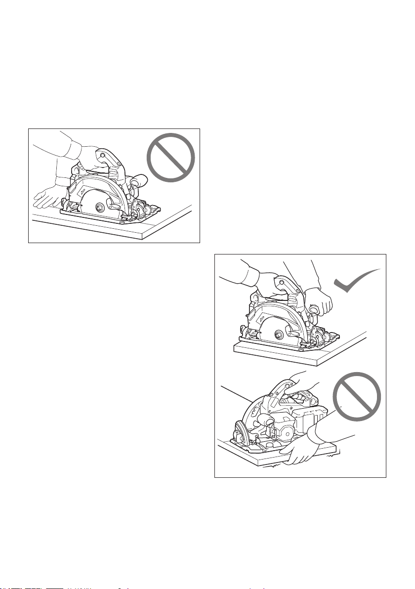
1.
DANGER:
Keep hands away from cutting area
and the blade. Keep your second hand on auxiliary
handle, or motor housing. If both hands are holding
the saw, they cannot be cut by the blade.
2. Do not reach underneath the workpiece. The
guard cannot protect you from the blade below the
workpiece.
3. Adjust the cutting depth to the thickness of
the workpiece. Less than a full tooth of the blade
teeth should be visible below the workpiece.
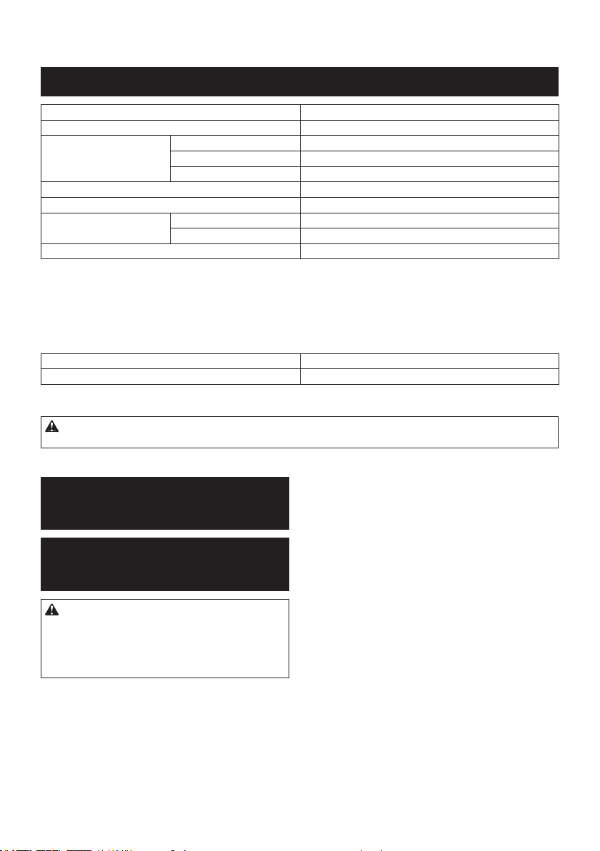
4. Never hold the workpiece in your hands or
across your leg while cutting. Secure the
workpiece to a stable platform. It is important to
support the work properly to minimise body expo-
sure, blade binding, or loss of control.
5. Hold the power tool by insulated gripping
surfaces, when performing an operation where
the cutting tool may contact hidden wiring.
Contact with a "live" wire will also make exposed
metal parts of the power tool "live" and could give
the operator an electric shock.
6. When ripping, always use a rip fence or
straight edge guide. This improves the accuracy
of cut and reduces the chance of blade binding.
7.
Always use blades with correct size and shape
(diamond versus round) of arbour holes. Blades that
do not match the mounting hardware of the saw will run
o-centre, causing loss of control.
8. Never use damaged or incorrect blade wash-
ers or bolt. The blade washers and bolt were
specially designed for your saw, for optimum
performance and safety of operation.
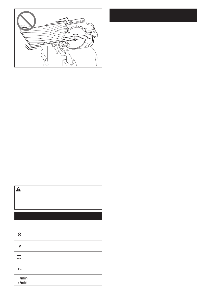
Kickback causes and related warnings
— kickback is a sudden reaction to a pinched,
jammed or misaligned saw blade, causing an
uncontrolled saw to lift up and out of the workpiece
toward the operator;
—
when the blade is pinched or jammed tightly by the kerf
closing down, the blade stalls and the motor reaction
drives the unit rapidly back toward the operator;
—
if the blade becomes twisted or misaligned in the cut,
the teeth at the back edge of the blade can dig into the
top surface of the wood causing the blade to climb out
of the kerf and jump back toward the operator.
Kickback is the result of saw misuse and/or incorrect
operating procedures or conditions and can be avoided
by taking proper precautions as given below.
1. Maintain a rm grip with both hands on the
saw and position your arms to resist kickback
forces. Position your body to either side of the
blade, but not in line with the blade. Kickback
could cause the saw to jump backwards, but
kickback forces can be controlled by the operator,
if proper precautions are taken.
2. When blade is binding, or when interrupting a
cut for any reason, release the trigger and hold
the saw motionless in the material until the
blade comes to a complete stop. Never attempt
to remove the saw from the work or pull the
saw backward while the blade is in motion
or kickback may occur. Investigate and take
corrective actions to eliminate the cause of blade
binding.
3. When restarting a saw in the workpiece, centre
the saw blade in the kerf so that the saw teeth
are not engaged into the material. If a saw blade
binds, it may walk up or kickback from the work-
piece as the saw is restarted.
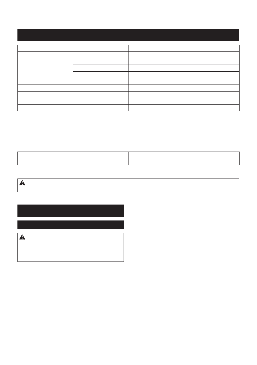
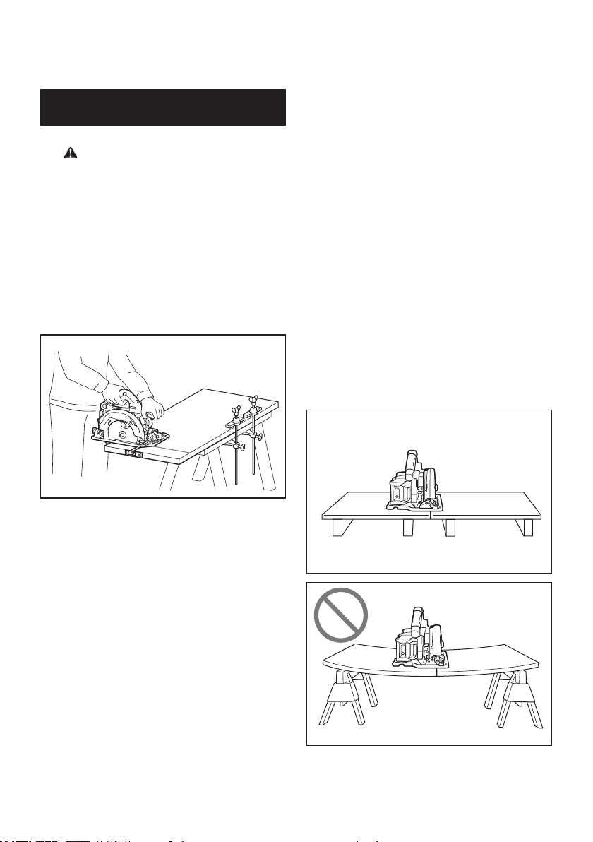
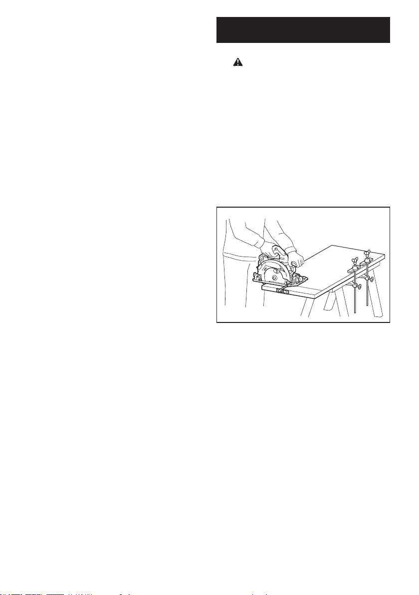
4. Support large panels to minimise the risk of
blade pinching and kickback. Large panels tend
to sag under their own weight. Supports must be
placed under the panel on both sides, near the line
of cut and near the edge of the panel.
5. Do not use dull or damaged blades.
Unsharpened or improperly set blades produce
narrow kerf causing excessive friction, blade
binding and kickback.
5 ENGLISH
6. Blade depth and bevel adjusting locking levers
must be tight and secure before making the
cut. If blade adjustment shifts while cutting, it may
cause binding and kickback.
7. Use extra caution when sawing into existing
walls or other blind areas. The protruding blade
may cut objects that can cause kickback.
8. ALWAYS hold the tool rmly with both hands.
NEVER place your hand, leg or any part of your
body under the tool base or behind the saw,
especially when making cross-cuts. If kickback
occurs, the saw could easily jump backwards over
your hand, leading to serious personal injury.
9. Never force the saw. Push the saw forward at a
speed so that the blade cuts without slowing.
Forcing the saw can cause uneven cuts, loss of
accuracy, and possible kickback.
Lower guard function
1. Check the lower guard for proper closing
before each use. Do not operate the saw if the
lower guard does not move freely and close
instantly. Never clamp or tie the lower guard
into the open position. If the saw is accidentally
dropped, the lower guard may be bent. Raise the
lower guard with the retracting handle and make
sure it moves freely and does not touch the blade
or any other part, in all angles and depths of cut.
2.
Check the operation of the lower guard spring. If
the guard and the spring are not operating prop-
erly, they must be serviced before use. Lower
guard may operate sluggishly due to damaged
parts, gummy deposits, or a build-up of debris.
3. The lower guard may be retracted manually
only for special cuts such as “plunge cuts”
and “compound cuts”. Raise the lower guard
by the retracting handle and as soon as the
blade enters the material, the lower guard
must be released. For all other sawing, the lower
guard should operate automatically.
4. Always observe that the lower guard is cover-
ing the blade before placing the saw down on
bench or oor. An unprotected, coasting blade
will cause the saw to walk backwards, cutting
whatever is in its path. Be aware of the time it
takes for the blade to stop after switch is released.
5. To check lower guard, open lower guard by
hand, then release and watch guard closure.
Also check to see that retracting handle does
not touch tool housing. Leaving blade exposed
is VERY DANGEROUS and can lead to serious
personal injury.
Additional safety warnings
1. Intended use
This tool is intended to cut wood products by
lengthways and crossways straight cuts and
miter cuts with angles while in rm contact
with the workpiece.
With appropriate Makita genuine circular saw
blades, other materials can also be sawed.
Accumulated sawdust on the lower guard and hub
from other materials may eect the proper closure
of the lower guard which could lead to serious
personal injury.
2. Use extra caution when cutting damp wood,
pressure treated lumber, or wood containing
knots. Maintain smooth advancement of tool with-
out decrease in blade speed to avoid overheating
the blade tips.
3. Do not attempt to remove cut material when
blade is moving. Wait until blade stops before
grasping cut material. Blades coast after turn o.
4. Avoid cutting nails. Inspect for and remove all
nails from lumber before cutting.
5. Place the wider portion of the saw base on
that part of the workpiece which is solidly
supported, not on the section that will fall o
when the cut is made. If the workpiece is short
or small, clamp it down. DO NOT TRY TO HOLD
SHORT PIECES BY HAND!
6. Before setting the tool down after completing a
cut, be sure that the guard has closed and the
blade has come to a complete stop.
7. Never attempt to saw with the circular saw
held upside down in a vise. This is extremely
dangerous and can lead to serious accidents.
6 ENGLISH
8.
Some material contains chemicals which may be toxic.
Take caution to prevent dust inhalation and skin con-
tact. Follow material supplier safety data.
9. Do not stop the blades by lateral pressure on
the saw blade.
10. Do not use any abrasive wheels.
11. Only use the saw blade with the diameter that
is marked on the tool or specied in the man-
ual. Use of an incorrectly sized blade may aect
the proper guarding of the blade or guard opera-
tion which could result in serious personal injury.
12.
Keep blade sharp and clean. Gum and wood pitch
hardened on blades slows saw and increases potential
for kickback. Keep blade clean by rst removing it from
tool, then cleaning it with gum and pitch remover, hot
water or kerosene. Never use gasoline.
13. Wear a dust mask and hearing protection when
use the tool.
14. Always use the saw blade intended for cutting
the material that you are going to cut.
15.
Only use the saw blades that are marked with a speed
equal or higher than the speed marked on the tool.
16. Place the tool and the parts on a at and stable
surface. Otherwise the tool or the parts may fall
and cause an injury.
SAVE THESE INSTRUCTIONS.
WARNING:
DO NOT let comfort or familiarity with
product (gained from repeated use) replace strict adher-
ence to safety rules for the subject product. MISUSE or
failure to follow the safety rules stated in this instruc-
tion manual may cause serious personal injury.
Symbols
The followings show the symbols used for tool.
diameter
volts
direct current
no load speed
revolutions or reciprocation per minute
Important safety instructions for
battery cartridge
1. Before using battery cartridge, read all instruc-
tions and cautionary markings on (1) battery
charger, (2) battery, and (3) product using
battery.
2. Do not disassemble or tamper the battery
cartridge. It may result in a re, excessive heat,
or explosion.
3. If operating time has become excessively
shorter, stop operating immediately. It may
result in a risk of overheating, possible burns
and even an explosion.
4. If electrolyte gets into your eyes, rinse them
out with clear water and seek medical atten-
tion right away. It may result in loss of your
eyesight.
5. Do not short the battery cartridge:
(1) Do not touch the terminals with any con-
ductive material.
(2) Avoid storing battery cartridge in a con-
tainer with other metal objects such as
nails, coins, etc.
(3) Do not expose battery cartridge to water
or rain.
A battery short can cause a large current
ow, overheating, possible burns and even a
breakdown.
6. Do not store the tool and battery cartridge in
locations where the temperature may reach or
exceed 50 °C (122 °F).
7. Do not incinerate the battery cartridge even if
it is severely damaged or is completely worn
out. The battery cartridge can explode in a re.
8. Do not nail, cut, crush, throw, drop the battery
cartridge, or hit against a hard object to the
battery cartridge. Such conduct may result in a
re, excessive heat, or explosion.
9. Do not use a damaged battery.
10. The contained lithium-ion batteries are subject
to the Dangerous Goods Legislation require-
ments.
For commercial transports e.g. by third parties,
forwarding agents, special requirement on pack-
aging and labeling must be observed.
For preparation of the item being shipped, consult-
ing an expert for hazardous material is required.
Please also observe possibly more detailed
national regulations.
Tape or mask o open contacts and pack up the
battery in such a manner that it cannot move
around in the packaging.
11. When disposing the battery cartridge, remove
it from the tool and dispose of it in a safe
place. Follow your local regulations relating to
disposal of battery.
12. Use the batteries only with the products
specied by Makita. Installing the batteries to
non-compliant products may result in a re, exces-
sive heat, explosion, or leak of electrolyte.
13. If the tool is not used for a long period of time,
the battery must be removed from the tool.

7 ENGLISH
14. During and after use, the battery cartridge may
take on heat which can cause burns or low
temperature burns. Pay attention to the han-
dling of hot battery cartridges.
15. Do not touch the terminal of the tool imme-
diately after use as it may get hot enough to
cause burns.
16. Do not allow chips, dust, or soil stuck into the
terminals, holes, and grooves of the battery
cartridge. It may result in poor performance or
breakdown of the tool or battery cartridge.
17. Unless the tool supports the use near a
high-voltage electrical power lines, do not use
the battery cartridge near a high-voltage elec-
trical power lines. It may result in a malfunction
or breakdown of the tool or battery cartridge.
SAVE THESE INSTRUCTIONS.
CAUTION: Only use genuine Makita batteries.
Use of non-genuine Makita batteries, or batteries that
have been altered, may result in the battery bursting
causing res, personal injury and damage. It will
also void the Makita warranty for the Makita tool and
charger.
Tips for maintaining maximum
battery life
1. Charge the battery cartridge before completely
discharged. Always stop tool operation and
charge the battery cartridge when you notice
less tool power.
2. Never recharge a fully charged battery car-
tridge. Overcharging shortens the battery
service life.
3. Charge the battery cartridge with room tem-
perature at 10 °C - 40 °C (50 °F - 104 °F). Let
a hot battery cartridge cool down before
charging it.
4. When not using the battery cartridge, remove
it from the tool or the charger.
5. Charge the battery cartridge if you do not use
it for a long period (more than six months).
Important safety instructions for
wireless unit
1. Do not disassemble or tamper with the wire-
less unit.
2. Keep the wireless unit away from young chil-
dren. If accidentally swallowed, seek medical
attention immediately.
3. Use the wireless unit only with Makita tools.
4. Do not expose the wireless unit to rain or wet
conditions.
5. Do not use the wireless unit in places where
the temperature exceeds 50°C (122°F).
6. Do not operate the wireless unit in places
where medical instruments, such as heart
pace makers are nearby.
7. Do not operate the wireless unit in places
where automated devices are nearby. If oper-
ated, automated devices may develop malfunction
or error.
8. Do not operate the wireless unit in places
under high temperature or places where
static electricity or electrical noise could be
generated.
9. The wireless unit can produce electromagnetic
elds (EMF) but they are not harmful to the
user.
10. The wireless unit is an accurate instrument. Be
careful not to drop or strike the wireless unit.
11. Avoid touching the terminal of the wireless
unit with bare hands or metallic materials.
12. Always remove the battery on the product
when installing the wireless unit into it.
13. When opening the lid of the slot, avoid the
place where dust and water may come into the
slot. Always keep the inlet of the slot clean.
14. Always insert the wireless unit in the correct
direction.
15. Do not press the wireless activation button
on the wireless unit too hard and/or press the
button with an object with a sharp edge.
16. Always close the lid of the slot when
operating.
17. Do not remove the wireless unit from the slot
while the power is being supplied to the tool.
Doing so may cause a malfunction of the wireless
unit.
18. Do not remove the sticker on the wireless unit.
19. Do not put any sticker on the wireless unit.
20. Do not leave the wireless unit in a place where
static electricity or electrical noise could be
generated.
21. Do not leave the wireless unit in a place sub-
ject to high heat, such as a car sitting in the
sun.
22. Do not leave the wireless unit in a dusty or
powdery place or in a place corrosive gas
could be generated.
23. Sudden change of the temperature may bedew
the wireless unit. Do not use the wireless unit
until the dew is completely dried.
24. When cleaning the wireless unit, gently wipe
with a dry soft cloth. Do not use benzine, thin-
ner, conductive grease or the like.
25. When storing the wireless unit, keep it in the
supplied case or a static-free container.
26. Do not insert any devices other than Makita
wireless unit into the slot on the tool.
27. Do not use the tool with the lid of the slot dam-
aged. Water, dust, and dirt come into the slot may
cause malfunction.
28. Do not pull and/or twist the lid of the slot more
than necessary. Restore the lid if it comes o
from the tool.
29. Replace the lid of the slot if it is lost or
damaged.
SAVE THESE INSTRUCTIONS.
8 ENGLISH
FUNCTIONAL
DESCRIPTION
CAUTION: Always be sure that the tool is
switched o and the battery cartridge is removed
before adjusting or checking function on the tool.
Installing or removing battery
cartridge
CAUTION: Always switch o the tool before
installing or removing of the battery cartridge.
CAUTION: Hold the tool and the battery car-
tridge rmly when installing or removing battery
cartridge. Failure to hold the tool and the battery
cartridge rmly may cause them to slip o your hands
and result in damage to the tool and battery cartridge
and a personal injury.
2
3
1
► 1. Red indicator 2. Button 3. Battery cartridge
To remove the battery cartridge, slide it from the tool
while sliding the button on the front of the cartridge.
To install the battery cartridge, align the tongue on the
battery cartridge with the groove in the housing and slip
it into place. Insert it all the way until it locks in place
with a little click. If you can see the red indicator on the
upper side of the button, it is not locked completely.
CAUTION: Always install the battery cartridge
fully until the red indicator cannot be seen. If not,
it may accidentally fall out of the tool, causing injury to
you or someone around you.
CAUTION: Do not install the battery cartridge
forcibly. If the cartridge does not slide in easily, it is
not being inserted correctly.
Tool / battery protection system
The tool is equipped with a tool/battery protection sys-
tem. This system automatically cuts o power to the
motor to extend tool and battery life. The tool will auto-
matically stop during operation if the tool or battery is
placed under one of the following conditions.
Overload protection
When the tool is operated in a manner that causes it to draw an
abnormally high current, the tool automatically stops. In this situa-
tion, turn the tool o and stop the application that caused the tool to
become overloaded. Then turn the tool on to restart.
Overheat protection
When the tool or battery is overheated, the tool stops
automatically and the lamp blinks. In this case, let the
tool and battery cool before turning the tool on again.
Overdischarge protection
When the battery capacity becomes low, the tool stops
automatically. If the product does not operate even
when the switches are operated, remove the batteries
from the tool and charge the batteries.
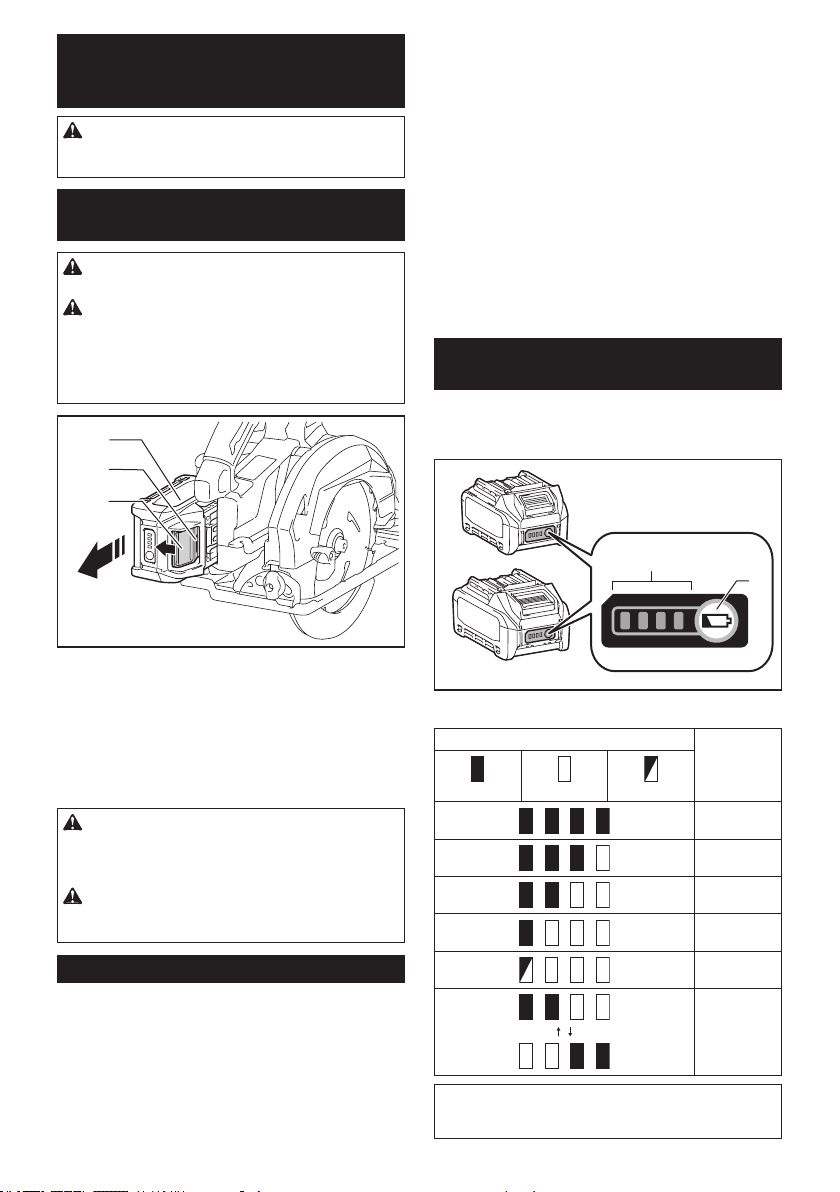
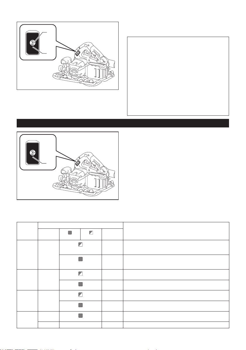
Indicating the remaining battery
capacity
Press the check button on the battery cartridge to indi-
cate the remaining battery capacity. The indicator lamps
light up for a few seconds.
1
2
► 1. Indicator lamps 2. Check button
Indicator lamps Remaining
capacity
Lighted O Blinking
75% to 100%
50% to 75%
25% to 50%
0% to 25%
Charge the
battery.
The battery
may have
malfunctioned.
NOTE: Depending on the conditions of use and the
ambient temperature, the indication may dier slightly
from the actual capacity.
9 ENGLISH
Switch action
WARNING: Before installing the battery car-
tridge into the tool, always check to see that the
switch trigger actuates properly and returns to
the "OFF" position when released.
WARNING: NEVER defeat the lock-o button
by taping down or some other means. A switch with
a negated lock-o button may result in unintentional
operation and serious personal injury.
WARNING: NEVER use the tool if it runs when
you simply pull the switch trigger without press-
ing the lock-o button. A switch in need of repair
may result in unintentional operation and serious
personal injury. Return tool to a Makita service center
for proper repairs BEFORE further usage.
To prevent the switch trigger from being accidentally
pulled, a lock-o button is provided. To start the tool,
depress the lock-o button and pull the switch trigger.
Release the switch trigger to stop.
2
1
► 1. Switch trigger 2. Lock-o button
NOTICE: Do not pull the switch trigger hard
without pressing in the lock-o button. This can
cause switch breakage.
CAUTION: The tool starts to brake the cir-
cular saw blade rotation immediately after you
release the switch trigger. Hold the tool rmly to
respond the reaction of the brake when releasing
the switch trigger. Sudden reaction can drop the tool
o your hand and can cause a personal injury.
Automatic speed change function
This tool has "high speed mode" and "high torque
mode".
The tool automatically changes the operation mode
depending on the work load. When the work load is low,
the tool will run in the "high speed mode" for quicker
cutting operation. When the work load is high, the tool
will run in the "high torque mode" for powerful cutting
operation.
1
► 1. Mode indicator
The mode indicator lights up in green when the tool is
running in "high torque mode".
If the tool is operated with excessive load, the mode
indicator will blink in green. The mode indicator stops
blinking and then lights up or turns o if you reduce the
load on the tool.
Mode indicator status Operation
mode
On O Blinking
High speed
mode
High torque
mode
Overload
alert
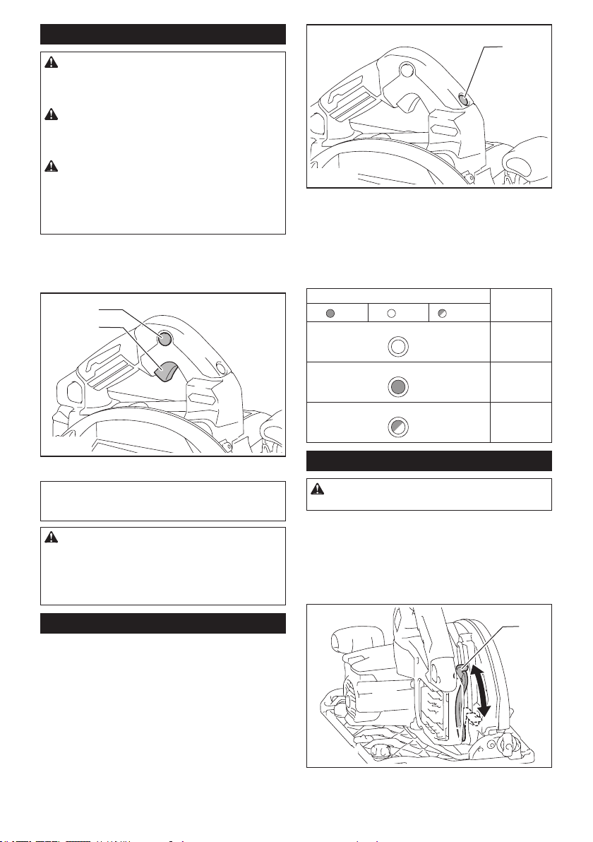
Adjusting depth of cut
CAUTION: After adjusting the depth of cut,
always tighten the lever securely.
Loosen the lever on the depth guide and move the base
up or down. At the desired depth of cut, secure the base
by tightening the lever.
For cleaner, safer cuts, set cut depth so that no more
than one blade tooth projects below workpiece. Using
proper cut depth helps to reduce potential for danger-
ous KICKBACKS which can cause personal injury.
1
► 1. Lever
10 ENGLISH
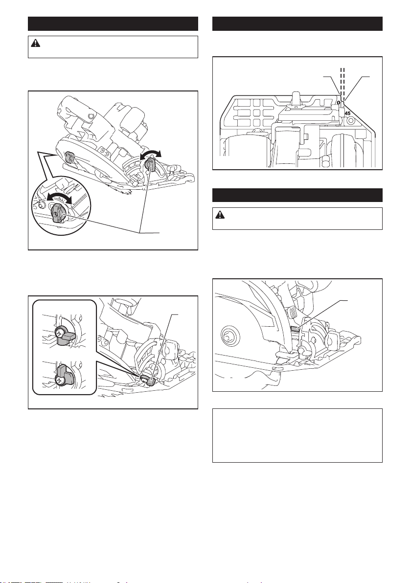
Bevel cutting
CAUTION: After adjusting the bevel angle,
always tighten the clamping screws securely.
Loosen the clamping screws. Set for the desired angle
by tilting accordingly, then tighten the clamping screws
securely.
1
► 1. Clamping screw
Use the stopper when you do precise 45° angle cutting.
Fully turn the stopper as illustrated depending on 0° -
45° bevel cut or 0° - 48° bevel cut.
1
0° - 45°
0° - 48°
► 1. Stopper
Sighting
For straight cuts, align the 0° position on the front of the base with
your cutting line. For 45° bevel cuts, align the 45° position with it.
1 2
► 1. Cutting line (0° position) 2. C
utting line (45° position)
Lighting the lamp
CAUTION: Do not look in the light or see the
source of light directly.
To turn on the lamp without running the tool, pull the
switch trigger without pressing the lock-o button.
To turn on the lamp with the tool running, press and hold
the lock-o button and pull the switch trigger.
The lamp goes out 10 seconds after releasing the switch trigger.
1
► 1. Lamp
NOTE: Use a dry cloth to wipe the dirt o the lens of
the lamp. Be careful not to scratch the lens of lamp, or
it may lower the illumination.
NOTE: When the tool is overheated, the lamp blinks
for one minute. In this case, cool down the tool before
another operation.
11 ENGLISH
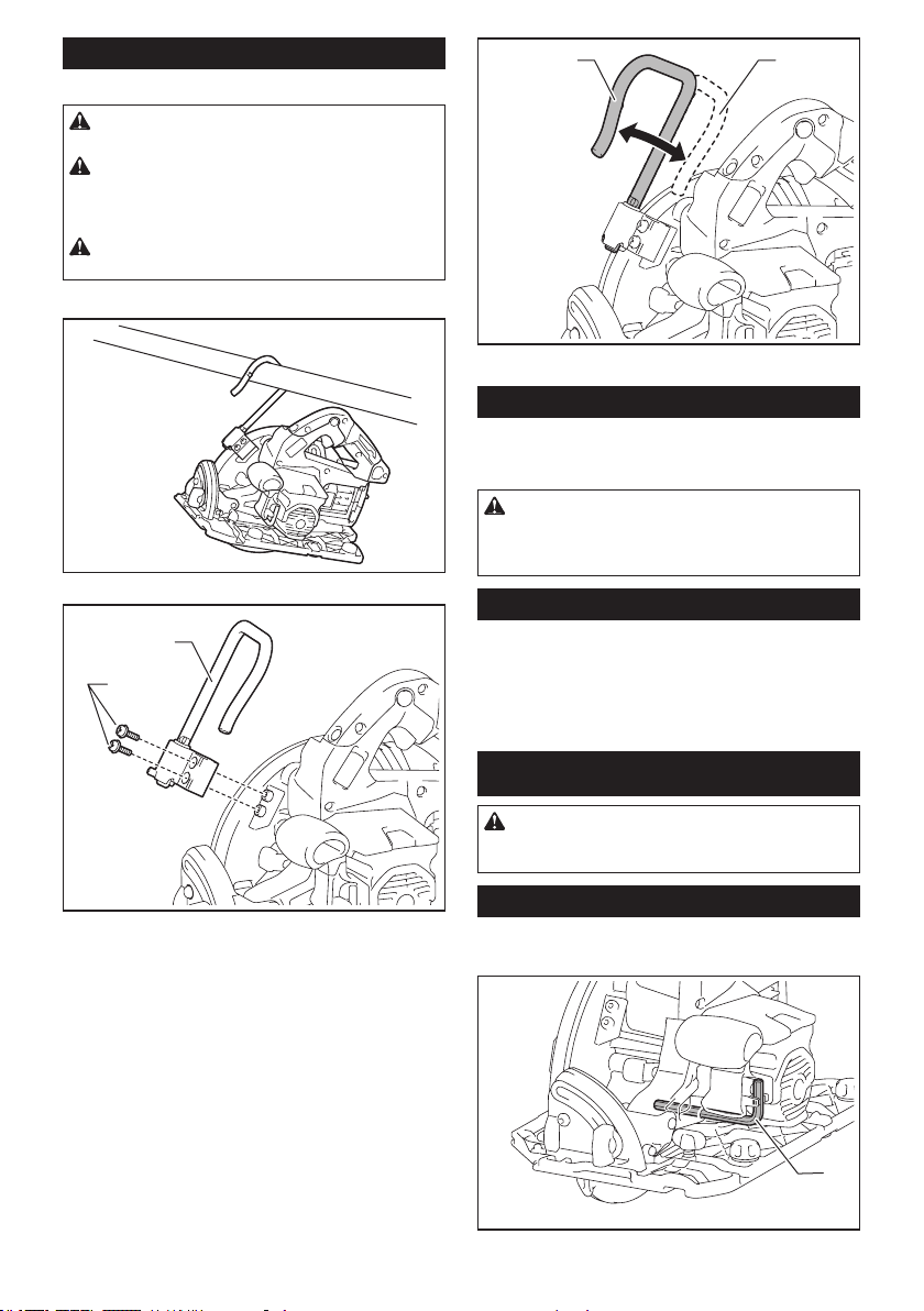
Hook
Optional accessory
CAUTION: Always remove the battery when
hanging the tool with the hook.
CAUTION: Never hook the tool at high loca-
tions or potentially unstable locations such as
on the surfaces. Otherwise the tool may lose the
balance and fall.
CAUTION: Do not pull the tool downward
when it is hooked.
The hook is convenient for hanging the tool temporarily.
Attach the hook with the screws as illustrated.
1
2
► 1. Hook 2. Screw
To use the hook, simply turn the hook until it snaps into
the open position.
When not in use, always turn the hook until it snaps into
the closed position.
1 2
► 1. Open position 2. Closed position
Electric brake
This tool is equipped with an electric blade brake. If the tool consis-
tently fails to quickly stop the circular saw blade after switch lever
release, have tool serviced at a Makita service center.
CAUTION: The blade brake system is not a
substitute for blade guard. NEVER USE TOOL
WITHOUT A FUNCTIONING BLADE GUARD.
SERIOUS PERSONAL INJURY CAN RESULT.
Electronic function
The tools equipped with electronic function are easy to
operate because of the following feature(s).
Soft start feature
Soft start because of suppressed starting shock.
ASSEMBLY
CAUTION: Always be sure that the tool is
switched o and the battery cartridge is removed
before carrying out any work on the tool.
Hex wrench storage
When not in use, store the hex wrench as shown in the
gure to keep it from being lost.
1
► 1. Hex wrench
12 ENGLISH
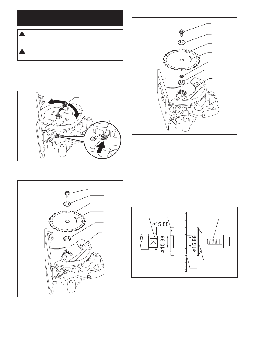
Removing or installing circular saw
blade
CAUTION: Be sure the circular saw blade is
installed with teeth pointing up at the front of the
tool.
CAUTION: Use only the Makita wrench to
install or remove the circular saw blade.
To remove the circular saw blade, press the shaft lock
fully so that the circular saw blade cannot revolve and
use the hex wrench to loosen the hex bolt. Then remove
the hex bolt, outer ange, circular saw blade and ring
(country specic).
2
1
4
3
► 1. Shaft lock 2. Hex wrench 3. Loosen 4. Tighten
For tool without the ring
1
2
3
4
5
6
► 1. Hex bolt 2. Outer ange 3. Circular saw blade
4. Arrow on the circular saw blade 5. Inner ange
6. Arrow on the tool
For tool with the ring
1
2
3
4
5
7
6
► 1. Hex bolt 2. Outer ange 3. Circular saw blade
4. Arrow on the circular saw blade 5. Ring 6. Inner
ange 7. Arrow on the tool
To install the circular saw blade, follow the removal
procedure in reverse.
Align the direction of the arrow on the blade with the
arrow on the tool.
Mount the inner ange with its recessed side facing
outward onto the mounting shaft and then place circu-
lar saw blade (with the ring attached if needed), outer
ange and hex bolt.
For tool without the ring
12
3
4
5
► 1. Mounting shaft 2. Inner ange 3. Circular saw
blade 4. Outer ange 5. Hex bolt
13 ENGLISH
For tool with the ring
12
3
4
5
6
15.88
15.88
15.88
► 1. Mounting shaft 2. Inner ange 3. Circular saw
blade 4. Outer ange 5. Hex bolt 6. Ring
WARNING: BE SURE TO TIGHTEN THE HEX
BOLT CLOCKWISE SECURELY. Also be careful
not to tighten the bolt forcibly. Slipping your hand
from the hex wrench can cause a personal injury.
WARNING: If the ring is needed to mount the
blade onto the spindle, always be sure that the
correct ring for the blade's arbor hole you intend
to use is installed between the inner and the outer
anges. Use of the incorrect arbor hole ring may
result in the improper mounting of the blade causing
blade movement and severe vibration resulting in
possible loss of control during operation and in seri-
ous personal injury.
Blade guard cleaning
When changing the circular saw blade, make sure to
also clean the upper and lower blade guards of accu-
mulated sawdust as discussed in the Maintenance
section. Such eorts do not replace the need to check
lower guard operation before each use.
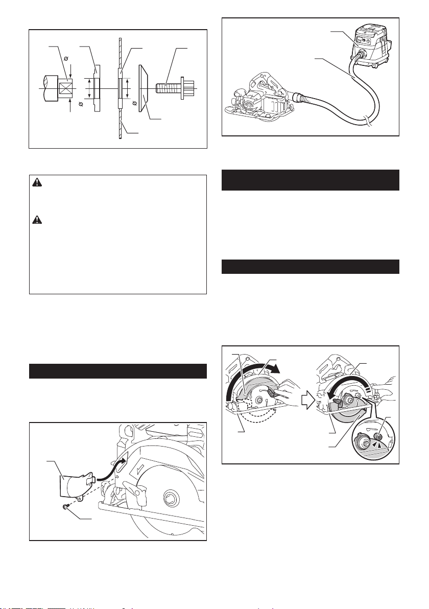
Connecting a vacuum cleaner
When you wish to perform clean cutting operation,
connect a Makita vacuum cleaner to your tool. Connect
a hose of the vacuum cleaner to the dust nozzle as
shown in the gure.
1
2
► 1. Dust nozzle 2. Screw
1
2
► 1. Hose 2. Vacuum cleaner
OPERATION
This tool is intended to cut wood products. With appro-
priate Makita genuine circular saw blades, following
materials can also be sawed:
• Aluminum products
Refer to our website or contact your local Makita dealer
for the correct circular saw blades to be used for the
material to be cut.
Checking blade guard function
Set the bevel angle to 0°, and then retract the lower
guard manually to the end and release it. The lower
guard is properly functioning if;
— it is retracted above the base without any hin-
drance and;
— it automatically returns and contacts with the
stopper.
1
1
2
2
3
4
5
6
3
► 1. Upper guard 2. Lower guard 3. Base 4. Stopper
5. Open 6. Close
If the lower guard is not functioning properly, check if
saw dust is accumulated inside of the upper and lower
guards. If the lower guard is not functioning properly
even after removing dust, have your tool serviced at a
Makita service center.
14 ENGLISH
Cutting operation
CAUTION: Wear dust mask when performing
cutting operation.
CAUTION: Be sure to move the tool forward
in a straight line gently. Forcing or twisting the tool
will result in overheating the motor and dangerous
kickback, possibly causing severe injury.
NOTE: When the battery cartridge temperature is
low, the tool may not work to its full capacity. At this
time, for example, use the tool for a light-duty cut for
a while until the battery cartridge warms up as high
as room temperature. Then, the tool can work to its
full capacity.
Hold the tool rmly. The tool is provided with both a front
grip and rear handle. Use both to best grasp the tool.
If both hands are holding saw, they cannot be cut by
the circular saw blade. Set the base on the workpiece
to be cut without the circular saw blade making any
contact. Then turn the tool on and wait until the circular
saw blade attains full speed. Now simply move the tool
forward over the workpiece surface, keeping it at and
advancing smoothly until the sawing is completed.
To get clean cuts, keep your sawing line straight and
your speed of advance uniform. If the cut fails to prop-
erly follow your intended cut line, do not attempt to turn
or force the tool back to the cut line. Doing so may bind
the circular saw blade and lead to dangerous kickback
and possible serious injury. Release switch, wait for cir-
cular saw blade to stop and then withdraw tool. Realign
tool on new cut line, and start cut again. Attempt to
avoid positioning which exposes operator to chips and
wood dust being ejected from saw. Use eye protection
to help avoid injury.
Rip fence (Guide rule)
CAUTION: Make sure that the rip fence is
securely installed in the correct position before
use. Improper attachment may cause dangerous
kickback.
1
2
► 1. Rip fence (Guide rule) 2. Clamping screw
The handy rip fence allows you to do extra-accurate
straight cuts. Simply slide the rip fence up snugly
against the side of the workpiece and secure it in posi-
tion with the clamping screw on the front of the base. It
also makes repeated cuts of uniform width possible.
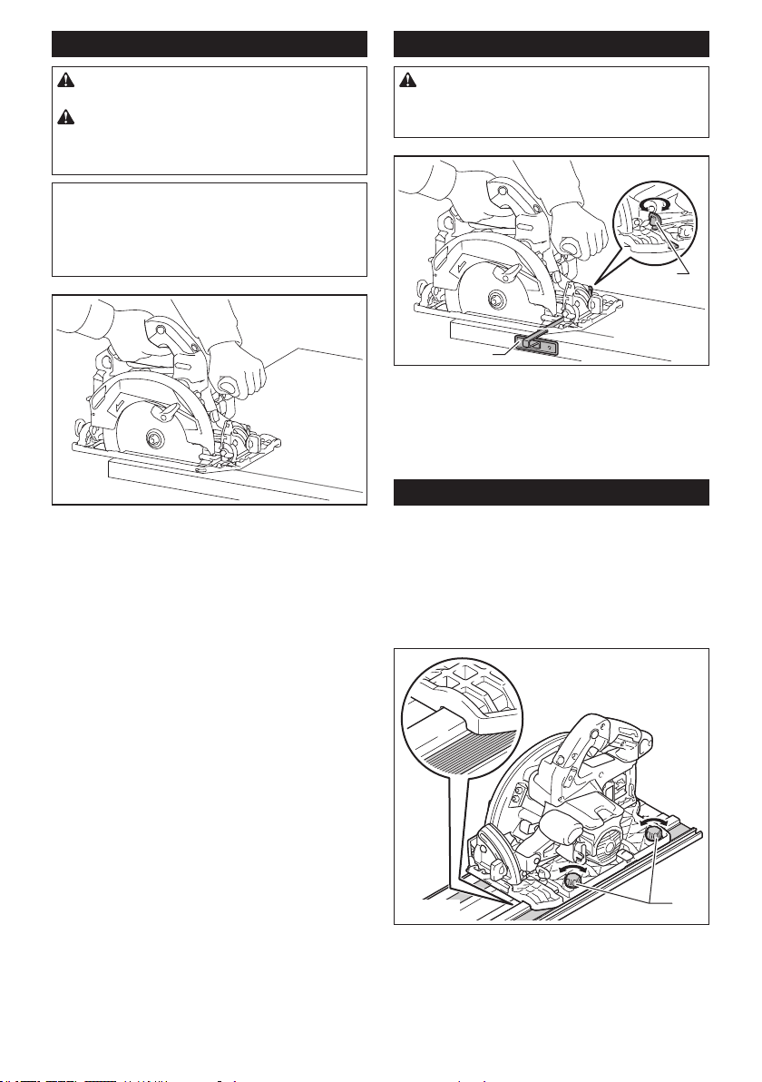
Guide rail
Optional accessory
Place the tool on the rear end of guide rail. Turn two
adjusting screws on the tool base so that the tool slides
smoothly without a clatter. Hold both the front grip and
rear handle of the tool rmly. Turn on the tool and cut
the splinter-guard along the full length with a stroke.
Now the edge of the splinter-guard corresponds to the
cutting edge.
1
► 1. Adjusting screws
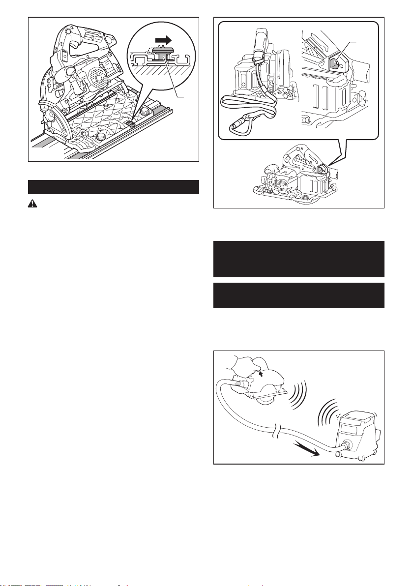
When bevel cutting with the guide rail, use the slide
lever to prevent the tool from falling over.
Move the slide lever on the tool base in the direction
of arrow so that it engages the undercut groove in the
guide rail.
15 ENGLISH
1
► 1. Slide lever
Lanyard (tether strap) connection
Safety warnings specic for use at height
Read all safety warnings and instructions. Failure to follow
the warnings and instructions may result in serious injury.
1. Always keep the tool tethered when working "at
height". Maximum lanyard length is 2 m (6.5 ft).
The maximum permissible fall height for lanyard
(tether strap) must not exceed 2 m (6.5 ft).
2. Use only with lanyards appropriate for this tool type
and rated for at least 7.0 kg (15.4 lbs).
3. Do not anchor the tool lanyard to anything on your
body or on movable components. Anchor the tool
lanyard to a rigid structure that can withstand the
forces of a dropped tool.
4. Make sure the lanyard is properly secured at each
end prior to use.
5. Inspect the tool and lanyard before each use for
damage and proper function (including fabric and
stitching). Do not use if damaged or not functioning
properly.
6. Do not wrap lanyards around or allow them to come
in contact with sharp or rough edges.
7. Fasten the other end of the lanyard outside the
working area so that a falling tool is held securely.
8.
Attach the lanyard so that the tool will move away from the
operator if it falls. Dropped tools will swing on the lanyard,
which could cause injury or loss of balance.
9. Do not use near moving parts or running machinery.
Failure to do so may result in a crush or entanglement
hazard.
10. Do not carry the tool by the attachment device or
the lanyard.
11. Only transfer the tool between your hands while you
are properly balanced.
12.
Do not attach lanyards to the tool in a way that keeps
guards, switches or lock-os from operating properly.
13. Avoid getting tangled in the lanyard.
14. Keep lanyard away from the cutting area of the tool.
15.
Use multi-action and screw gate type carabineers.
Do not use single action spring clip carabineers.
16.
In the event the tool is dropped, it must be tagged
and removed from service, and should be inspected
by a Makita Factory or Authorized Service Center.
1
► 1. Hole for lanyard (tether strap)
WIRELESS ACTIVATION
FUNCTION
What you can do with the wireless
activation function
The wireless activation function enables clean and com-
fortable operation. By connecting a supported vacuum
cleaner to the tool, you can run the vacuum cleaner
automatically along with the switch operation of the tool.
To use the wireless activation function, prepare following items:
• A wireless unit (optional accessory)
• A vacuum cleaner which supports the wireless
activation function
The overview of the wireless activation function setting
is as follows. Refer to each section for detail procedures.
1. Installing the wireless unit
2. Tool registration for the vacuum cleaner
3. Starting the wireless activation function
16 ENGLISH
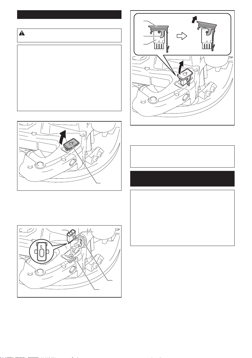
Installing the wireless unit
Optional accessory
CAUTION: Place the tool on a at and stable
surface when installing the wireless unit.
NOTICE: Clean the dust and dirt on the tool
before installing the wireless unit. Dust or dirt
may cause malfunction if it comes into the slot of the
wireless unit.
NOTICE: To prevent the malfunction caused by
static, touch a static discharging material, such
as a metal part of the tool, before picking up the
wireless unit.
NOTICE: When installing the wireless unit,
always be sure that the wireless unit is inserted
in the correct direction and the lid is completely
closed.
1. Open the lid on the tool as shown in the gure.
1
► 1. Lid
2. Insert the wireless unit to the slot and then close
the lid.
When inserting the wireless unit, align the projections
with the recessed portions on the slot.
2
1
3
4
► 1. Wireless unit 2. Projection 3. Lid 4. Recessed
portion
When removing the wireless unit, open the lid slowly.
The hooks on the back of the lid will lift the wireless unit
as you pull up the lid.
1
2
3
► 1. Wireless unit 2. Hook 3. Lid
After removing the wireless unit, keep it in the supplied
case or a static-free container.
NOTICE: Always use the hooks on the back of
the lid when removing the wireless unit. If the
hooks do not catch the wireless unit, close the lid
completely and open it slowly again.
Tool registration for the vacuum
cleaner
NOTE: A Makita vacuum cleaner supporting the
wireless activation function is required for the tool
registration.
NOTE: Finish installing the wireless unit to the tool
before starting the tool registration.
NOTE: During the tool registration, do not pull the
switch trigger or turn on the power switch on the
vacuum cleaner.
NOTE: Refer to the instruction manual of the vacuum
cleaner, too.
17 ENGLISH
If you wish to activate the vacuum cleaner along with
the switch operation of the tool, nish the tool registra-
tion beforehand.
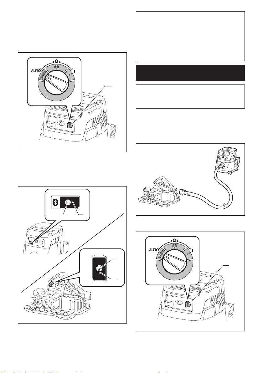
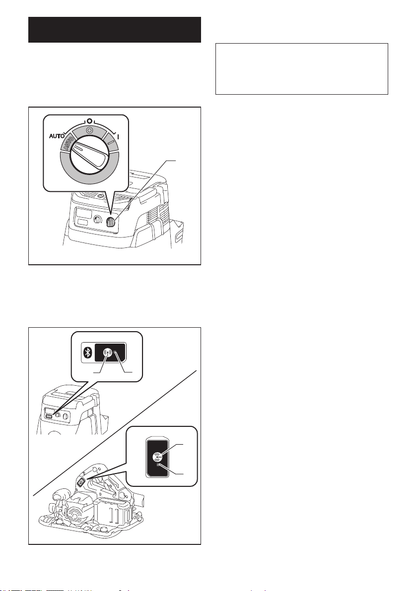
1. Install the batteries to the vacuum cleaner and the
tool.
2. Set the stand-by switch on the vacuum cleaner to
"AUTO".
1
► 1. Stand-by switch
3. Press the wireless activation button on the vac-
uum cleaner for 3 seconds until the wireless activation
lamp blinks in green. And then press the wireless acti-
vation button on the tool in the same way.
2
1
2
1
► 1. Wireless activation button 2. Wireless activation
lamp
If the vacuum cleaner and the tool are linked success-
fully, the wireless activation lamps will light up in green
for 2 seconds and start blinking in blue.
NOTE: The wireless activation lamps nish blinking
in green after 20 seconds elapsed. Press the wireless
activation button on the tool while the wireless acti-
vation lamp on the cleaner is blinking. If the wireless
activation lamp does not blink in green, push the wire-
less activation button briey and hold it down again.
NOTE: When performing two or more tool registra-
tions for one vacuum cleaner, nish the tool registra-
tion one by one.
Starting the wireless activation
function
NOTE: Finish the tool registration for the vacuum
cleaner prior to the wireless activation.
NOTE: Refer to the instruction manual of the vacuum
cleaner, too.
After registering a tool to the vacuum cleaner, the
vacuum cleaner will automatically runs along with the
switch operation of the tool.
1. Install the wireless unit to the tool.
2.
Connect the hose of the vacuum cleaner with the tool.
3. Set the stand-by switch on the vacuum cleaner to
"AUTO".
1
► 1. Stand-by switch
18 ENGLISH
4. Push the wireless activation button on the tool
briey. The wireless activation lamp will blink in blue.
1
2
► 1. Wireless activation button 2. Wireless activation
lamp
5. Pull the switch trigger of the tool. Check if the
vacuum cleaner runs while the switch trigger is being
pulled.
To stop the wireless activation of the vacuum cleaner,
push the wireless activation button on the tool.
NOTE: The wireless activation lamp on the tool will
stop blinking in blue when there is no operation for
2 hours. In this case, set the stand-by switch on the
vacuum cleaner to "AUTO" and push the wireless
activation button on the tool again.
NOTE: The vacuum cleaner starts/stops with a delay.
There is a time lag when the vacuum cleaner detects
a switch operation of the tool.
NOTE: The transmission distance of the wireless unit
may vary depending on the location and surrounding
circumstances.
NOTE: When two or more tools are registered to one
vacuum cleaner, the vacuum cleaner may start run-
ning even if you do not pull the switch trigger because
another user is using the wireless activation function.
Description of the wireless activation lamp status
1
► 1. Wireless activation lamp
The wireless activation lamp shows the status of the wireless activation function. Refer to the table below for the
meaning of the lamp status.
Status Wireless activation lamp Description
Color
On
Blinking
Duration
Standby Blue
2 hours The wireless activation of the vacuum cleaner is available. The
lamp will automatically turn o when no operation is performed
for 2 hours.
When
the tool is
running.
The wireless activation of the vacuum cleaner is available and the
tool is running.
Tool
registration
Green
20 seconds Ready for the tool registration. Waiting for the registration by the
vacuum cleaner.
2 seconds The tool registration has been nished. The wireless activation
lamp will start blinking in blue.
Cancelling
tool
registration
Red
20 seconds Ready for the cancellation of the tool registration. Waiting for the
cancellation by the vacuum cleaner.
2 seconds The cancellation of the tool registration has been nished. The
wireless activation lamp will start blinking in blue.
Others Red
3 seconds The power is supplied to the wireless unit and the wireless activa-
tion function is starting up.
O - - The wireless activation of the vacuum cleaner is stopped.
19 ENGLISH
Cancelling tool registration for the
vacuum cleaner
Perform the following procedure when cancelling the
tool registration for the vacuum cleaner.
1. Install the batteries to the vacuum cleaner and the
tool.
2. Set the stand-by switch on the vacuum cleaner to
"AUTO".
1
► 1. Stand-by switch
3. Press the wireless activation button on the vac-
uum cleaner for 6 seconds. The wireless activation
lamp blinks in green and then become red. After that,
press the wireless activation button on the tool in the
same way.
2
1
2
1
► 1. Wireless activation button 2. Wireless activation
lamp
If the cancellation is performed successfully, the wire-
less activation lamps will light up in red for 2 seconds
and start blinking in blue.
NOTE: The wireless activation lamps nish blinking in
red after 20 seconds elapsed. Press the wireless acti-
vation button on the tool while the wireless activation
lamp on the cleaner is blinking. If the wireless acti-
vation lamp does not blink in red, push the wireless
activation button briey and hold it down again.

20 ENGLISH
Troubleshooting for wireless activation function
Before asking for repairs, conduct your own inspection rst. If you nd a problem that is not explained in the manual,
do not attempt to dismantle the tool. Instead, ask Makita Authorized Service Centers, always using Makita replace-
ment parts for repairs.
State of abnormality Probable cause (malfunction) Remedy
The wireless activation lamp does
not light/blink.
The wireless unit is not installed into
the tool.
The wireless unit is improperly installed
into the tool.
Install the wireless unit correctly.
The terminal of the wireless unit and/or
the slot is dirty.
Gently wipe o dust and dirt on the terminal of the
wireless unit and clean the slot.
The wireless activation button on the
tool has not been pushed.
Push the wireless activation button on the tool
briey.
The stand-by switch on the vacuum
cleaner is not set to "AUTO".
Set the stand-by switch on the vacuum cleaner to
"AUTO".
No power supply Supply the power to the tool and the vacuum
cleaner.
Cannot nish tool registration / can-
celling tool registration successfully.
The wireless unit is not installed into
the tool.
The wireless unit is improperly installed
into the tool.
Install the wireless unit correctly.
The terminal of the wireless unit and/or
the slot is dirty.
Gently wipe o dust and dirt on the terminal of the
wireless unit and clean the slot.
The stand-by switch on the vacuum
cleaner is not set to "AUTO".
Set the stand-by switch on the vacuum cleaner to
"AUTO".
No power supply Supply the power to the tool and the vacuum
cleaner.
Incorrect operation Push the wireless activation button briey and
perform the tool registration/cancellation procedures
again.
The tool and vacuum cleaner are away
from each other (out of the transmission
range).
Get the tool and vacuum cleaner closer to each
other. The maximum transmission distance is
approximately 10 m however it may vary according
to the circumstances.
Before nishing the tool registration/
cancellation;
- the switch trigger on the tool is pulled
or;
- the power button on the vacuum
cleaner is turned on.
Push the wireless activation button briey and
perform the tool registration/cancellation procedures
again.
The tool registration procedures for
the tool or vacuum cleaner have not
nished.
Perform the tool registration procedures for both the
tool and the vacuum cleaner at the same timing.
Radio disturbance by other appliances
which generate high-intensity radio
waves.
Keep the tool and vacuum cleaner away from the
appliances such as Wi-Fi devices and microwave
ovens.
21 ENGLISH
State of abnormality Probable cause (malfunction) Remedy
The vacuum cleaner does not run
along with the switch operation of
the tool.
The wireless unit is not installed into
the tool.
The wireless unit is improperly installed
into the tool.
Install the wireless unit correctly.
The terminal of the wireless unit and/or
the slot is dirty.
Gently wipe o dust and dirt on the terminal of the
wireless unit and clean the slot.
The wireless activation button on the
tool has not been pushed.
Push the wireless activation button briey and make
sure that the wireless activation lamp is blinking
in blue.
The stand-by switch on the vacuum
cleaner is not set to "AUTO".
Set the stand-by switch on the vacuum cleaner to
"AUTO".
More than 10 tools are registered to the
vacuum cleaner.
Perform the tool registration again.
If more than 10 tools are registered to the vacuum
cleaner, the tool registered earliest will be cancelled
automatically.
The vacuum cleaner erased all tool
registrations.
Perform the tool registration again.
No power supply Supply the power to the tool and the vacuum
cleaner.
The tool and vacuum cleaner are away
from each other (out of the transmission
range).
Get the tool and vacuum cleaner closer each other.
The maximum transmission distance is approxi-
mately 10 m however it may vary according to the
circumstances.
Radio disturbance by other appliances
which generate high-intensity radio
waves.
Keep the tool and vacuum cleaner away from the
appliances such as Wi-Fi devices and microwave
ovens.
The vacuum cleaner runs while the
tool's switch trigger is not pulled.
Other users are using the wireless
activation of the vacuum cleaner with
their tools.
Turn o the wireless activation button of the other
tools or cancel the tool registration of the other
tools.
MAINTENANCE
CAUTION: Always be sure that the tool is
switched o and the battery cartridge is removed
before attempting to perform inspection or
maintenance.
CAUTION: Clean out the upper and lower
guards to ensure there is no accumulated saw-
dust which may impede the operation of the lower
guarding system. A dirty guarding system may limit
the proper operation which could result in serious
personal injury. The most eective way to accomplish
this cleaning is with compressed air. If the dust is
being blown out of the guards, be sure the proper
eye and breathing protection is used.
CAUTION: After each use, wipe o the saw
dust on the tool. Fine saw dust may come inside the
tool and cause malfunction or a re.
NOTICE: Never use gasoline, benzine, thinner,
alcohol or the like. Discoloration, deformation or
cracks may result.
To maintain product SAFETY and RELIABILITY,
repairs, any other maintenance or adjustment should
be performed by Makita Authorized or Factory Service
Centers, always using Makita replacement parts.
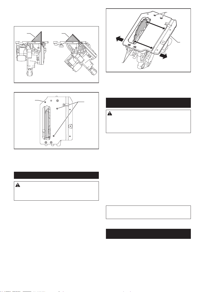
Adjusting 0°-cut or 45°-cut accuracy
This adjustment has been made at the factory. But if it is
o, you can adjust it as the following procedure.
1. Loosen the clamping screws on the front and rear
of the tool so that the bevel angle can be changed. Set
the stopper to 0° - 45° bevel angle position if you are
going to adjust 45°-cut accuracy.
1
2
► 1. Clamping screw 2. Stopper
22 ENGLISH
2. Make the base perpendicular or 45° to the circular
saw blade using a triangular rule by turning the adjust-
ing screw with a hex wrench. You can also use a square
rule to adjust 0° angle.
1 1
► 1. Triangular rule
2
1
► 1. Adjusting screw for 0° angle 2. Adjusting screw
for 45° angle
3. Tighten the clamping screws and then make a test
cut to check if desired angle is obtained.
Adjusting the parallelism
CAUTION: Keep the parallelism accurate.
Otherwise the circular saw blade may bite into the
guide rail and the damaged guide rail may cause an
injury.
This adjustment has been made at the factory. But if it is
o, you can adjust it as the following procedure.
1. Set the tool to the maximum cutting depth.
2. Make sure all levers and screws are tightened.
3. Loosen the screws shown in the gure.
4. While opening the lower guard, move the rear of
the base so that the distance A and B becomes equal.
1
B
A
2
1
► 1. Screw 2. Base
5. Tighten the screws and make a test cut to check
the parallelism.
OPTIONAL ACCESSORIES
CAUTION:
These accessories or attachments are
recommended for use with your Makita tool specied in
this manual. The use of any other accessories or attach-
ments might present a risk of injury to persons. Only use
accessory or attachment for its stated purpose.
If you need any assistance for more details regarding these
accessories, ask your local Makita Service Center.
• Circular saw blade
• Rip fence (Guide rule)
• Hook
• Guide rail
• Bevel guide
• Clamp
• Sheet
• Rubber sheet
• Position sheet
• Dust nozzle
• Hex wrench
• Wireless unit
• Makita genuine battery and charger
NOTE: Some items in the list may be included in the
tool package as standard accessories. They may
dier from country to country.
MAKITA LIMITED WARRANTY
Please refer to the annexed warranty sheet for the most
current warranty terms applicable to this product.If annexed
warranty sheet is not available, refer to the warranty details
set forth at below website for your respective country.
United States of America: www.makitatools.com
Canada: www.makita.ca
Other countries: www.makita.com
23 ESPAÑOL
ESPAÑOL (Instrucciones originales)
ESPECIFICACIONES
Modelo: GSH02
Diámetro del disco 185 mm (7-1/4″)
Profundidad de corte máxima a 0° 60,0 mm (2-3/8″)
bisel a 45° 43,0 mm (1-11/16″)
bisel a 48° 41,0 mm (1-5/8″)
Velocidad sin carga 6 000 r/min
Tensión nominal 36 V - 40 V c.c. máx.
Longitud total con el modelo BL4025 322 mm (12-5/8″)
con el modelo BL4040 337 mm (13-1/4″)
Peso neto 4,4 kg - 4,7 kg (9,7 lbs - 10,4 lbs)
• Debido a nuestro continuo programa de investigación y desarrollo, las especicaciones aquí incluidas están
sujetas a cambio sin previo aviso.
• Las especicaciones y el cartucho de batería pueden variar de país a país.
• El peso puede variar en función de los accesorios, incluido el cartucho de batería. En la tabla se muestra la
combinación de peso más ligero y más pesado conforme al procedimiento 01/2014 de EPTA.
Cartucho de batería y cargador aplicables
Cartucho de batería BL4025/BL4040
Cargador DC40RA
• Algunos de los cartuchos de batería y cargadores enumerados arriba podrían no estar disponibles depen-
diendo de su área de residencia.
ADVERTENCIA: Use únicamente los cartuchos de batería y los cargadores indicados arriba. El uso de
cualquier otro cartucho de batería y cargador podría ocasionar una lesión y/o un incendio.
ADVERTENCIAS DE
SEGURIDAD
Advertencias generales de
seguridad para herramientas
eléctricas
ADVERTENCIA: Lea todas las advertencias
de seguridad, instrucciones, ilustraciones y espe-
cicaciones suministradas con esta herramienta
eléctrica. El no seguir todas las instrucciones indi-
cadas a continuación podría ocasionar una descarga
eléctrica, incendio y/o lesiones graves.
Conserve todas las advertencias
e instrucciones como referencia
en el futuro.
En las advertencias, el término “herramienta eléctrica”
se reere a su herramienta eléctrica de funcionamiento
con conexión a la red eléctrica (con cableado eléctrico)
o herramienta eléctrica de funcionamiento a batería
(inalámbrica).
Seguridad en el área de trabajo
1. Mantenga el área de trabajo limpia y bien ilu-
minada. Las áreas oscuras o desordenadas son
propensas a accidentes.
2. No utilice las herramientas eléctricas en
atmósferas explosivas, tal como en la presen-
cia de líquidos, gases o polvo inamables. Las
herramientas eléctricas crean chispas que pueden
prender fuego al polvo o los humos.
3. Mantenga a los niños y curiosos alejados
mientras utiliza una herramienta eléctrica. Las
distracciones le pueden hacer perder el control.
Seguridad eléctrica
1.
Las clavijas de conexión de las herramientas eléc-
tricas deberán encajar perfectamente en la toma de
corriente. No modique nunca la clavija de cone-
xión de ninguna forma. No utilice ninguna clavija
adaptadora con herramientas eléctricas que tengan
conexión a tierra (puesta a tierra). La utilización de
clavijas no modicadas y que encajen perfectamente
en la toma de corriente reducirá el riesgo de que se
produzca una descarga eléctrica.
2.
Evite tocar con el cuerpo supercies conectadas a
tierra o puestas a tierra tales como tubos, radiado-
res, cocinas y refrigeradores. Si su cuerpo es puesto
a tierra o conectado a tierra existirá un mayor riesgo de
que sufra una descarga eléctrica.

24 ESPAÑOL
3. No exponga las herramientas eléctricas a la
lluvia ni a condiciones húmedas. La entrada de
agua en una herramienta eléctrica aumentará el
riesgo de que se produzca una descarga eléctrica.
4. No maltrate el cable. Nunca utilice el cable
para transportar, jalar o desconectar la herra-
mienta eléctrica. Mantenga el cable alejado del
calor, aceite, objetos cortantes o piezas móvi-
les. Los cables dañados o enredados aumentan
el riesgo de sufrir una descarga eléctrica.
5.
Cuando utilice una herramienta eléctrica en exte-
riores, utilice un cable de extensión apropiado para
uso en exteriores. La utilización de un cable apropiado
para uso en exteriores reducirá el riesgo de que se
produzca una descarga eléctrica.
6. Si no es posible evitar usar una herramienta
eléctrica en condiciones húmedas, utilice un
alimentador protegido con interruptor de cir-
cuito de falla a tierra (ICFT). El uso de un ICFT
reduce el riesgo de descarga eléctrica.
7. Las herramientas eléctricas pueden producir
campos electromagnéticos (CEM) que no son
dañinos para el usuario. Sin embargo, si los
usuarios tienen marcapasos y otros dispositivos
médicos similares, deberán consultar al fabricante
de su dispositivo y/o a su médico antes de operar
esta herramienta eléctrica.
Seguridad personal
1. Manténgase alerta, preste atención a lo que
está haciendo y utilice su sentido común
cuando opere una herramienta eléctrica. No
utilice una herramienta eléctrica cuando esté
cansado o bajo la inuencia de drogas, alco-
hol o medicamentos. Un momento de distracción
mientras opera las herramientas eléctricas puede
terminar en una lesión grave.
2. Use equipo de protección personal. Póngase
siempre protección para los ojos. El equipo
protector tal como máscara contra el polvo, zapa-
tos de seguridad antiderrapantes, casco rígido y
protección para oídos utilizado en las condiciones
apropiadas reducirá el riesgo de lesiones.
3.
Impida el encendido accidental. Asegúrese de que
el interruptor esté en la posición de apagado antes
de conectar a la alimentación eléctrica y/o de colo-
car el cartucho de batería, así como al levantar o
cargar la herramienta. Cargar las herramientas eléc-
tricas con su dedo en el interruptor o enchufarlas con
el interruptor encendido hace que los accidentes sean
comunes.
4. Retire cualquier llave de ajuste o llave de
apriete antes de encender la herramienta. Una
llave de ajuste o llave de apriete que haya sido
dejada puesta en una parte giratoria de la herra-
mienta eléctrica puede ocasionar alguna lesión.
5.
No utilice la herramienta donde no alcance.
Mantenga los pies sobre suelo rme y el equilibrio
en todo momento. Esto permite un mejor control de la
herramienta eléctrica en situaciones inesperadas.
6. Use una vestimenta apropiada. No use ropa
suelta ni alhajas. Mantenga el cabello, la ropa
y los guantes alejados de las piezas móviles.
Las prendas de vestir holgadas, las alhajas y
el cabello largo suelto podrían engancharse en
estas piezas móviles.
7. Si dispone de dispositivos para la conexión
de equipos de extracción y recolección de
polvo, asegúrese de conectarlos y utilizarlos
debidamente. Hacer uso de la recolección de
polvo puede reducir los riesgos relacionados con
el polvo.
8. No permita que la familiaridad adquirida
debido al uso frecuente de las herramientas
haga que se sienta conado e ignore los prin-
cipios de seguridad de las herramientas. Un
descuido podría ocasionar una lesión grave en
una fracción de segundo.
9. Utilice siempre gafas protectoras para prote-
ger sus ojos de lesiones al usar herramientas
eléctricas. Las gafas deben cumplir con la
Norma ANSI Z87.1 en EUA.
Es responsabilidad del empleador imponer
el uso de equipos protectores de seguridad
apropiados a los operadores de la herramienta
y demás personas cerca del área de trabajo.
Mantenimiento y uso de la herramienta eléctrica
1. No fuerce la herramienta eléctrica. Utilice la
herramienta eléctrica correcta para su aplica-
ción. La herramienta eléctrica adecuada hará un
mejor trabajo y de forma más segura a la veloci-
dad para la que ha sido fabricada.
2. No utilice la herramienta eléctrica si el inte-
rruptor no la enciende y apaga. Cualquier
herramienta eléctrica que no pueda ser contro-
lada con el interruptor es peligrosa y debe ser
reemplazada.
3. Desconecte la clavija de la fuente de alimen-
tación y/o retire la batería de la herramienta
eléctrica, en caso de ser removible, antes de
realizar ajustes, cambiar accesorios o almace-
nar las herramientas eléctricas. Tales medidas
de seguridad preventivas reducirán el riesgo
de poner en marcha la herramienta eléctrica de
forma accidental.
4. Guarde la herramienta eléctrica que no use
fuera del alcance de los niños y no permita
que las personas que no están familiarizadas
con ella o con las instrucciones la operen. Las
herramientas eléctricas son peligrosas en manos
de personas que no saben operarlas.
5.
Dé mantenimiento a las herramientas eléctricas
y los accesorios. Compruebe que no haya piezas
móviles desalineadas o estancadas, piezas rotas
y cualquier otra condición que pueda afectar al
funcionamiento de la herramienta eléctrica. Si la
herramienta eléctrica está dañada, haga que la repa-
ren antes de utilizarla. Muchos de los accidentes son
ocasionados por no dar un mantenimiento adecuado a
las herramientas eléctricas.
6.
Mantenga las herramientas de corte limpias y
losas. Si recibe un mantenimiento adecuado y tiene
los bordes alados, es probable que la herramienta se
atasque menos y sea más fácil controlarla.
7. Utilice la herramienta eléctrica, los accesorios
y las brocas de acuerdo con estas instruccio-
nes, considerando las condiciones laborales
y el trabajo a realizar. Si utiliza la herramienta
eléctrica para realizar operaciones distintas de
las indicadas, podrá presentarse una situación
peligrosa.
25 ESPAÑOL
8. Mantenga los mangos y supercies de asi-
miento secos, limpios y libres de aceite o
grasa. Los mangos y supercies de asimiento
resbalosos no permiten una manipulación segura
ni el control de la herramienta en situaciones
inesperadas.
9. Cuando vaya a utilizar esta herramienta, evite
usar guantes de trabajo de tela ya que éstos
podrían atorarse. Si los guantes de trabajo de
tela llegaran a atorarse en las piezas móviles,
esto podría ocasionar lesiones personales.
Uso y cuidado de la herramienta a batería
1. Recargue sólo con el cargador especicado
por el fabricante. Un cargador que es adecuado
para un solo tipo de batería puede generar riesgo
de incendio al ser utilizado con otra batería.
2. Utilice las herramientas eléctricas solamente
con las baterías designadas especícamente
para ellas. La utilización de cualquier otra batería
puede crear un riesgo de lesiones o incendio.
3. Cuando no se esté usando la batería, mantén-
gala alejada de otros objetos metálicos, como
sujetapapeles (clips), monedas, llaves, clavos,
tornillos u otros objetos pequeños de metal
los cuales pueden actuar creando una cone-
xión entre las terminales de la batería. Originar
un cortocircuito en las terminales puede causar
quemaduras o incendios.
4. En condiciones abusivas, podrá escapar
líquido de la batería; evite tocarlo. Si lo toca
accidentalmente, enjuague con agua. Si hay
contacto del líquido con los ojos, busque asis-
tencia médica. Puede que el líquido expulsado
de la batería cause irritación o quemaduras.
5. No utilice una herramienta ni una batería que
estén dañadas o hayan sido modicadas. Las
baterías dañadas o modicadas podrían oca-
sionar una situación inesperada provocando un
incendio, explosión o riesgo de lesiones.
6. No exponga la herramienta ni la batería al
fuego ni a una temperatura excesiva. La expo-
sición al fuego o a una temperatura superior a los
130 °C podría causar una explosión.
7. Siga todas las instrucciones para la carga y
evite cargar la herramienta o la batería fuera
del rango de temperatura especicado en
las instrucciones. Una carga inadecuada o a
una temperatura fuera del rango especicado
podría dañar la batería e incrementar el riesgo de
incendio.
Servicio
1. Haga que una persona calicada repare la
herramienta eléctrica utilizando sólo piezas de
repuesto idénticas. Esto asegura que se man-
tenga la seguridad de la herramienta eléctrica.
2. Nunca dé servicio a baterías que estén daña-
das. El servicio a las baterías solamente deberá
ser efectuado por el fabricante o un agente de
servicio autorizado.
3. Siga las instrucciones para la lubricación y
cambio de accesorios.
4. No modique ni intente reparar el aparato ni el
paquete de baterías salvo como se indique en
las instrucciones para el uso y cuidado.
Advertencias de seguridad para la
sierra circular inalámbrica
Procedimientos de corte
1.
PELIGRO: Mantenga las manos alejadas
del área de corte y del disco. Mantenga su
segunda mano sobre el mango auxiliar o sobre
la carcasa del motor. Si ambas manos sujetan la
sierra no pueden sufrir cortes del disco.
2. Nunca meta la mano por debajo de la pieza
de trabajo. El protector no puede protegerle del
disco debajo de la pieza de trabajo.
3. Ajuste la profundidad de corte al grosor de la
pieza de trabajo. Debe verse menos de un diente
completo por debajo de la pieza de trabajo.
4.
Nunca sostenga la pieza de trabajo con sus manos
ni a través de su pierna durante el corte. Asegure la
pieza de trabajo a una plataforma estable. Es impor-
tante apoyar la pieza de trabajo adecuadamente para
reducir la exposición del cuerpo, el atascamiento del
disco o la pérdida de control.
5. Cuando realice una operación en la que la
herramienta de corte pueda entrar en contacto
con cableado oculto, sujete la herramienta
eléctrica por las supercies de asimiento
aisladas. El contacto con un cable con corriente
también hará que la corriente circule por las par-
tes metálicas expuestas de la herramienta eléc-
trica y podría ocasionar una descarga eléctrica al
operador.
6. Cuando realice un corte longitudinal, utilice
siempre un tope lateral de corte o una guía de
borde recto. Esto mejora la precisión del corte y
reduce la posibilidad de que el disco se atasque.
7. Utilice siempre discos del tamaño y forma
correctos (diamante versus circular) de los
oricios para ejes. Los discos que no encajen
con el equipo de montaje de la sierra se desequili-
brarán ocasionando la pérdida de control.
8. Nunca utilice arandelas o pernos de disco
dañados o incorrectos. El perno y las arandelas
del disco se han diseñado especícamente para
su sierra, para una seguridad y un rendimiento
óptimos.
Causas de los retrocesos bruscos y advertencias
relacionadas
— el retroceso brusco es una reacción repentina
a un disco de la sierra pellizcado, atascado
o desalineado, que ocasiona que una sierra
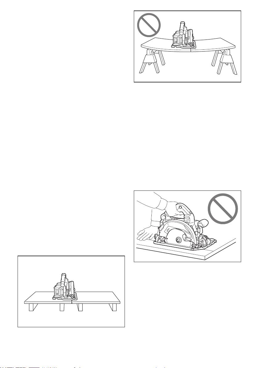
26 ESPAÑOL
descontrolada se levante y la pieza de trabajo
salga disparada hacia el operador;
— cuando el disco queda fuertemente pellizcado o
atascado al cerrarse la línea de corte, el disco se
detiene y la reacción del motor es dirigir rápida-
mente la unidad hacia el operador;
— si el disco se retuerce o está mal alineado en el
corte, los dientes del borde posterior del disco
pueden clavarse en la supercie posterior de la
madera, haciendo que el disco escale la línea de
corte y salte hacia el operador.
El retroceso brusco es el resultado de un mal uso de
la sierra y/o de condiciones o procedimientos de uso
incorrectos y se puede evitar tomando las precauciones
que se indican a continuación.
1. Sujete la sierra rmemente con las dos manos
y coloque sus brazos de forma que ofrezcan
resistencia a la fuerza del retroceso brusco.
Coloque su cuerpo hacia cualquiera de los
lados del disco, pero no en línea con él. El
retroceso brusco puede provocar que la sierra
salte hacia atrás; no obstante, el operador puede
controlar la fuerza del retroceso brusco si toma las
precauciones adecuadas.
2. Cuando note que el disco se atora, o cuando
quiera interrumpir un corte por cualquier
razón, suelte el gatillo y mantenga la sierra
inmóvil en el material hasta que el disco se
pare completamente. No intente nunca extraer
la sierra de la pieza de trabajo ni tirar de la sie-
rra hacia atrás mientras el disco esté movién-
dose porque podrá ocasionar un retroceso
brusco. Investigue y tome medidas correctivas
para eliminar la causa del atoramiento del disco.
3. Cuando reinicie la sierra en la pieza de trabajo,
centre el disco de la sierra en la línea de corte
de manera que los dientes de la sierra no que-
den enganchados en el material. Si el disco de
la sierra llegara a trabarse, éste podría levantarse
y sufrir un retroceso brusco desde la pieza de
trabajo al reiniciarse la sierra.
4. Sujete los paneles grandes para minimizar el
riesgo de que el disco se estanque y dé un
retroceso brusco. Los paneles grandes tienden
a hundirse bajo su propio peso. Deben colocarse
soportes bajo el panel en ambos lados, cerca de
la línea de corte y del borde del panel.
5.
No utilice discos dañados o desalados. Las discos
colocados incorrectamente o desalados producen un
corte más angosto y causan una fricción excesiva, que
el disco se doble y retrocesos bruscos.
6. Las palancas de jación de los ajustes de pro-
fundidad y de bisel del disco deben ser apreta-
das y aseguradas antes de realizar el corte. Si
el ajuste del disco cambia durante el corte, podrá
ocasionar un atoramiento y retroceso brusco.
7. Tenga especial cuidado cuando realice cortes
con sierra en paredes existentes u otras áreas
ciegas. El disco protuberante puede cortar obje-
tos que pueden provocar retrocesos bruscos.
8.
SIEMPRE sostenga rmemente la herramienta con
ambas manos. NUNCA coloque su mano, pierna ni
cualquier parte de su cuerpo debajo de la base de la
herramienta ni detrás de la sierra, especialmente al
hacer cortes longitudinales. Si se llega a dar un retroceso
brusco, la herramienta podría fácilmente saltar hacia atrás
sobre su mano, ocasionando lesiones personales graves.
9.
Nunca fuerce la sierra. Empuje la sierra hacia ade-
lante a una velocidad a la que el disco corte sin
desacelerarse. Forzar la sierra durante el corte puede
producir cortes desiguales, perder precisión y posible-
mente generar un retroceso brusco.
Función del protector
1. Compruebe que el protector inferior esté bien
cerrado antes de cada uso. No utilice la sierra
si el protector inferior no se mueve libremente
y se cierra instantáneamente. Nunca sujete ni
mantenga el protector inferior en la posición
abierta. Si la sierra cae accidentalmente, el pro-
tector inferior se puede doblar. Levante el pro-
tector inferior con el mango retráctil y asegúrese
de que se mueve libremente y de que no hace
contacto con el disco ni con ninguna otra pieza en
todos los ángulos y profundidades de corte.
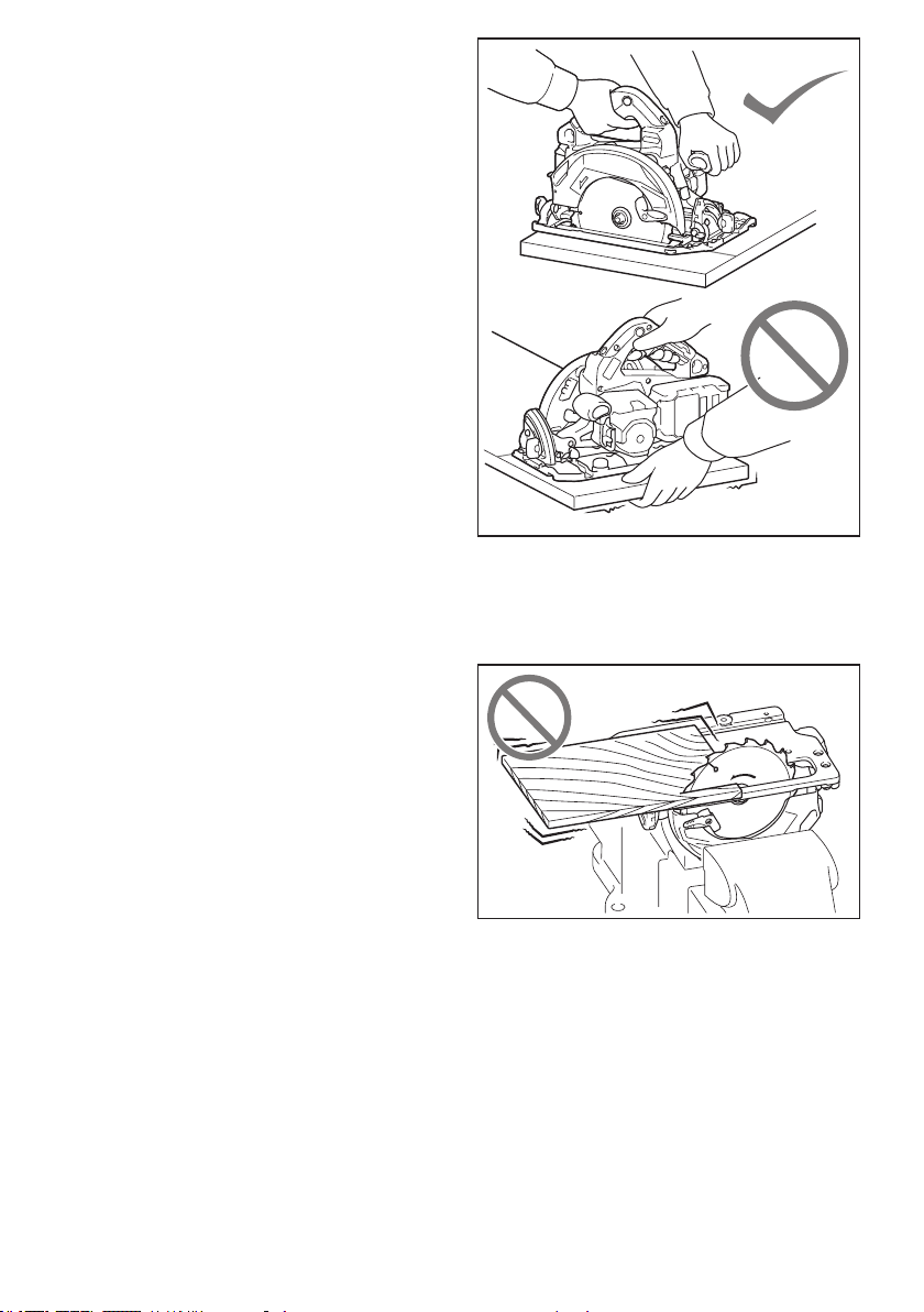
27 ESPAÑOL
2. Compruebe el funcionamiento del muelle del
protector inferior. Si el protector y el muelle
no funcionan correctamente, deben repararse
antes de utilizar la herramienta. El protector
inferior puede funcionar con lentitud debido a las
piezas dañadas, depósitos pegajosos o acumula-
ción de suciedad.
3. El protector inferior debe retraerse manual-
mente sólo para cortes especiales tales como
“cortes de inmersión” y “cortes compues-
tos”. Levante el protector inferior mediante
el mango retráctil y cuando el disco entre en
el material, debe soltar el protector inferior.
Para todos los otros cortes con sierra, el protector
inferior debe funcionar automáticamente.
4. Antes de dejar la sierra en el banco o en
el suelo, observe siempre que el protector
inferior esté cubriendo el disco. Un disco des-
protegido, girando por inercia, hará que la sierra
se desplace hacia atrás, cortando todo lo que
encuentre a su paso. Tenga presente el tiempo
que el disco tarda en detenerse después de soltar
el interruptor.
5. Para revisar el protector inferior, ábralo
manualmente, suéltelo y vea que cierre. Revise
también que el mango retráctil no toque el
alojamiento de la herramienta. Dejar el disco
expuesto es MUY PELIGROSO y puede ocasio-
nar lesiones personales graves.
Advertencias de seguridad adicionales
1. Uso pretendido
Esta herramienta está diseñada para cortar
productos de madera por medio de cortes rec-
tos longitudinales y transversales, así como
cortes en inglete con ángulos, mientras está
apoyada rmemente con la pieza de trabajo.
Con los discos de la sierra circulares apropia-
dos y originales de Makita también se puede
cortar otro tipo de materiales.
La acumulación de aserrín en el protector inferior
y el eje generada por otros materiales puede
afectar el cierre correcto del protector inferior y
ocasionar lesiones personales graves.
2. Proceda con extrema precaución al cortar
madera húmeda, tratada a presión o con
nudos. Mantenga un avance suave de la herra-
mienta sin reducir la velocidad del disco para
evitar el sobrecalentamiento de las puntas del
mismo.
3. No intente retirar material cortado cuando el
disco se está moviendo. Espere hasta que el
disco se detenga antes de recoger el material
cortado. Los discos siguen girando por inercia
después de apagar la herramienta.
4. Evite cortar clavos. Inspeccione la madera
y quite todos los clavos antes de realizar el
corte.
5. Coloque la parte más ancha de la base de la
sierra sobre la pieza de trabajo que está sujeta
rmemente, no sobre la sección que caerá
cuando se realice el corte. Si la pieza de tra-
bajo es corta o pequeña, fíjela. ¡NO INTENTE
SUJETAR PIEZAS PEQUEÑAS CON LA MANO!
6.
Antes de depositar la herramienta tras realizar un
corte, asegúrese de que el protector esté cerrado y
de que el disco se haya detenido por completo.
7. Nunca intente serrar con la sierra circular boca
arriba en una prensa. Es extremadamente peli-
groso y puede conllevar accidentes graves.
8.
Algunos materiales contienen sustancias químicas
que pueden ser tóxicas. Tome precauciones para
evitar la inhalación de polvo o que éste tenga con-
tacto con la piel. Consulte la hoja de seguridad del
proveedor de los materiales.
9. No detenga el disco de la sierra mediante
presión lateral sobre el mismo.
10. No use ningún disco abrasivo.
11. Use solamente un disco de la sierra cuyo
diámetro esté marcado en la herramienta o
especicado en el manual. El uso de un disco
de la sierra de tamaño inadecuado puede afectar
la protección del disco o del protector en sí, lo cual
podría ocasionar lesiones graves al operador.
12. Mantenga el disco alado y limpio. La cola y la
resina de madera endurecidas en el disco frenan
la sierra y aumentan las posibilidades de que se
28 ESPAÑOL
produzcan retrocesos bruscos. Mantenga limpio
el disco quitándolo primero de la herramienta y
limpiándolo con eliminador de resina y goma,
agua caliente o queroseno. Nunca utilice gasolina.
13. Utilice una máscara antipolvo y protección
para los oídos cuando utilice la herramienta.
14. Siempre utilice el disco de la sierra previsto
para el material que va a cortar.
15. Utilice únicamente los discos de la sierra mar-
cados con una velocidad igual o mayor a la
velocidad marcada en la herramienta.
16. Coloque la herramienta y las piezas sobre una
supercie plana y estable. De lo contrario, la
herramienta o las piezas podrían caerse y ocasio-
nar una lesión.
GUARDE ESTAS
INSTRUCCIONES.
ADVERTENCIA: NO DEJE que la comodidad
o familiaridad con el producto (a base de utilizarlo
repetidamente) sustituya la estricta observancia
de las normas de seguridad para dicho producto.
El MAL USO o el no seguir las normas de seguri-
dad establecidas en este manual de instrucciones
puede ocasionar lesiones personales graves.
Símbolos
A continuación se muestran los símbolos utilizados
para la herramienta.
diámetro
volts o voltios
corriente directa o continua
velocidad sin carga
revoluciones o alternaciones por minuto,
frecuencia de rotación
Instrucciones importantes de seguridad
para el cartucho de batería
1. Antes de utilizar el cartucho de batería, lea
todas las instrucciones e indicaciones de
precaución en el (1) el cargador de batería, (2)
la batería, y (3) el producto con el que se utiliza
la batería.
2. No desarme ni modique el cartucho de bate-
ría. Podría ocurrir un incendio, calor excesivo o
una explosión.
3. Si el tiempo de operación se ha acortado en
exceso, deje de operar de inmediato. Podría
correrse el riesgo de sobrecalentamiento,
posibles quemaduras e incluso explosión.
4. En caso de que ingresen electrolitos en sus
ojos, enjuáguelos bien con agua limpia y con-
sulte de inmediato a un médico. Esto podría
ocasionar pérdida de visión.
5. Evite cortocircuitar el cartucho de batería:
(1) No toque las terminales con ningún mate-
rial conductor.
(2) Evite guardar el cartucho de batería en un
cajón junto con otros objetos metálicos,
tales como clavos, monedas, etc.
(3) No exponga el cartucho de batería al
agua o la lluvia.
Un cortocircuito en la batería puede causar
un ujo grande de corriente, sobrecalenta-
miento, posibles quemaduras e incluso una
descompostura.
6. No guarde la herramienta ni el cartucho de
batería en lugares donde la temperatura pueda
alcanzar o exceder los 50°C (122°F).
7. Nunca incinere el cartucho de batería incluso
en el caso de que esté dañado seriamente o
ya no sirva en absoluto. El cartucho de batería
puede explotar si se tira al fuego.
8.
No clave, corte, aplaste, lance o deje caer el cartu-
cho de batería, ni golpee un objeto sólido contra el
cartucho de batería. Dicha acción podría resultar en
un incendio, calor excesivo o en una explosión.
9. No use una batería dañada.
10. Las baterías de ión de litio están sujetas a los
requisitos reglamentarios en materia de bie-
nes peligrosos.
Para el trasporte comercial, por ej., mediante
terceros o agentes de transporte, se deben tomar
en cuenta los requisitos especiales relativos al
empaque y el etiquetado.
Para efectuar los preparativos del artículo que se
va a enviar, se requiere consultar a un experto
en materiales peligrosos. Si es posible, consulte
además otras regulaciones nacionales más deta-
lladas.
Pegue o cubra con cinta adhesiva los contactos
abiertos y empaque la batería de manera que ésta
no pueda moverse dentro del paquete.
11. Para deshacerse del cartucho de batería,
sáquelo de la herramienta y deséchelo en un
lugar seguro. Siga las regulaciones locales
relacionadas al desecho de las baterías.
12.
Utilice las baterías únicamente con los productos
especicados por Makita. Instalar las baterías en
productos que no cumplan con los requisitos podría
ocasionar un incendio, un calentamiento excesivo, una
explosión o una fuga de electrolito.
13. Si no se utiliza la herramienta por un
período largo, debe extraerse la batería de la
herramienta.
14. El cartucho de batería podría absorber calor
durante y después de su uso, lo que ocasiona-
ría quemaduras o quemaduras a baja tempe-
ratura. Tenga cuidado con la manipulación de
los cartuchos de batería que estén calientes.
15. No toque el terminal de la herramienta inme-
diatamente después de su uso, ya que el
mismo podría estar lo sucientemente caliente
como para provocarle quemaduras.
16. No permita que las rebabas, el polvo o la tierra
queden atrapados en los terminales, oricios
y ranuras del cartucho de batería. Esto podría
ocasionar un desempeño deciente o descompos-
tura de la herramienta o del cartucho de batería.

29 ESPAÑOL
17. No utilice el cartucho de batería cerca de
cables eléctricos de alto voltaje, a menos que
la herramienta sea compatible con el uso cer-
cano a estos cables eléctricos de alto voltaje.
Esto podría ocasionar una avería o descompos-
tura de la herramienta o del cartucho de batería.
GUARDE ESTAS
INSTRUCCIONES.
PRECAUCIÓN: Utilice únicamente baterías
originales de Makita. El uso de baterías no origina-
les de Makita, o de baterías alteradas, puede ocasio-
nar que las baterías exploten causando un incendio,
lesiones personales y daños. Asimismo, esto inva-
lidará la garantía de Makita para la herramienta y el
cargador Makita.
Consejos para alargar al máximo
la vida útil de la batería
1. Cargue el cartucho de batería antes de que
se descargue completamente. Pare siem-
pre la operación y cargue el cartucho de
batería cuando note menos potencia en la
herramienta.
2. No cargue nunca un cartucho de batería que
esté completamente cargado. La sobrecarga
acortará la vida de servicio de la batería.
3. Cargue el cartucho de batería a una tempera-
tura ambiente de 10 °C - 40 °C (50 °F - 104 °F).
Si un cartucho de batería está caliente, déjelo
enfriar antes de cargarlo.
4. Cuando no utilice el cartucho de batería,
sáquelo de la herramienta o del cargador.
5. Cargue el cartucho de batería si no va a utili-
zarlo durante un período prolongado (más de
seis meses).
Instrucciones importantes
de seguridad para la unidad
inalámbrica
1. No desarme ni modique la unidad
inalámbrica.
2. Mantenga la unidad inalámbrica alejada de
los niños pequeños. En caso de ingerirla
accidentalmente, solicite atención médica de
inmediato.
3. Utilice la unidad inalámbrica solamente con
herramientas de Makita.
4. No exponga la unidad inalámbrica a la lluvia ni
a condiciones de humedad.
5. No utilice la unidad inalámbrica en lugares
donde la temperatura exceda los 50°C (122°F).
6. No utilice la unidad inalámbrica en lugares
donde haya instrumentos médicos tales como
marcapasos cerca.
7. No utilice la unidad inalámbrica en lugares
donde haya dispositivos automáticos cerca.
Si se utiliza, los dispositivos automáticos podrían
causar alguna avería o error.
8. No opere la unidad inalámbrica en lugares con
alta temperatura o donde pueda generarse
electricidad estática o ruido eléctrico.
9. La unidad inalámbrica puede producir campos
electromagnéticos (CEM), sin embargo éstos
no son dañinos para el usuario.
10. La unidad inalámbrica es un instrumento de
precisión. Tenga cuidado de no dejar caer ni
golpear la unidad inalámbrica.
11. Evite tocar la terminal de la unidad inalámbrica
con las manos descubiertas o con materiales
metálicos.
12. Retire siempre la batería del producto al insta-
lar en él la unidad inalámbrica.
13. Cuando abra la tapa de la ranura, evite el lugar
donde el polvo y el agua puedan introducirse
en la ranura. Mantenga siempre la entrada de
la ranura limpia.
14. Inserte siempre la unidad inalámbrica en la
dirección correcta.
15. No oprima el botón de activación inalámbrica
en la unidad inalámbrica demasiado fuerte, ni
lo haga con ningún objeto que tenga un borde
loso.
16. Cierre siempre la tapa de la ranura durante la
operación.
17. No retire la unidad inalámbrica de la ranura
mientras se esté suministrando energía a la
herramienta. El hacerlo podría causar una avería
de la unidad inalámbrica.
18. No retire la etiqueta en la unidad inalámbrica.
19. No coloque ninguna etiqueta en la unidad
inalámbrica.
20. No deje la unidad inalámbrica en un lugar
donde pueda generarse electricidad estática o
ruido eléctrico.
21. No deje la unidad inalámbrica en un lugar
sujeto a temperaturas altas, tal como un vehí-
culo estacionado bajo el sol.
22. No deje la unidad inalámbrica en un lugar
donde haya polvo o suciedad ni en un lugar
donde pueda generarse gas corrosivo.
23. Los cambios repentinos de temperatura
podrían humedecer la unidad inalámbrica. No
utilice la unidad inalámbrica hasta que la con-
densación se haya secado por completo.
24. Cuando vaya a limpiar la unidad inalámbrica,
hágalo cuidadosamente usando un paño
suave seco. No utilice bencina, disolvente,
grasa conductora o sustancias similares.
25. Cuando vaya a almacenar la unidad inalám-
brica, guárdela en el estuche suministrado o
en un contenedor libre de electricidad estática.
26. No inserte ningún otro dispositivo que no sea
la unidad inalámbrica de Makita en la ranura de
la herramienta.
27. No utilice la herramienta si la tapa de la ranura
está dañada. La entrada de agua, polvo o sucie-
dad en la ranura podría causar una avería.
28. No jale ni tuerza la tapa de la ranura más de
lo necesario. Vuelva a colocar la tapa si ésta se
sale de la herramienta.
29. Reemplace la tapa de la ranura si llega a per-
derse o dañarse.
GUARDE ESTAS
INSTRUCCIONES.
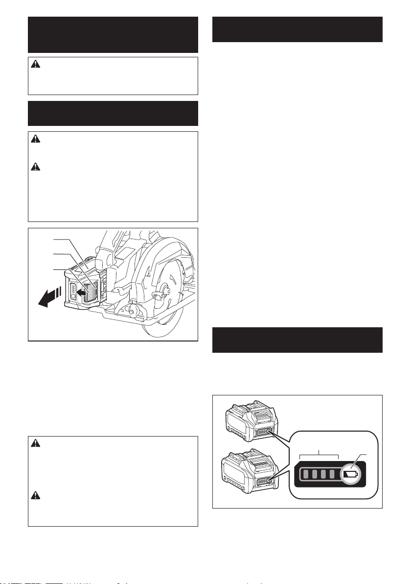
30 ESPAÑOL
DESCRIPCIÓN DEL
FUNCIONAMIENTO
PRECAUCIÓN: Asegúrese siempre de que la
herramienta esté apagada y el cartucho de batería
haya sido extraído antes de realizar cualquier
ajuste o comprobación en la herramienta.
Instalación o extracción del
cartucho de batería
PRECAUCIÓN: Apague siempre la herra-
mienta antes de colocar o quitar el cartucho de
batería.
PRECAUCIÓN: Sujete la herramienta y el car-
tucho de la batería con rmeza al colocar o quitar
el cartucho de batería. Si no se sujeta con rmeza la
herramienta y el cartucho de batería, puede ocasio-
nar que se resbalen de sus manos causando daños
a la herramienta y al cartucho de batería, así como
lesiones a la persona.
2
3
1
► 1. Indicador rojo 2. Botón 3. Cartucho de batería
Para quitar el cartucho de batería, deslícelo de la herra-
mienta mientras desliza el botón sobre la parte delan-
tera del cartucho.
Para colocar el cartucho de batería, alinee la lengüeta
sobre el cartucho de batería con la ranura en la carcasa
y deslice en su lugar. Inserte por completo hasta que
se je en su lugar con un pequeño clic. Si puede ver el
indicador rojo del lado superior del botón, esto indica
que no ha quedado jo por completo.
PRECAUCIÓN: Introduzca siempre com-
pletamente el cartucho de batería hasta que
el indicador rojo no pueda verse. Si no, podría
accidentalmente salirse de la herramienta y caer al
suelo causando una lesión a usted o alguien a su
alrededor.
PRECAUCIÓN: No instale el cartucho de
batería a la fuerza. Si el cartucho no se desliza al
interior fácilmente, se debe a que no está siendo
insertado correctamente.
Sistema de protección para la
herramienta/batería
La herramienta está equipada con un sistema de pro-
tección para la herramienta/batería. Este sistema corta
en forma automática el suministro de energía al motor
para prolongar la vida útil de la herramienta y la batería.
La herramienta se detendrá automáticamente durante
la operación si la herramienta o la batería se someten a
una de las siguientes condiciones. En algunas condicio-
nes, los indicadores pueden encenderse.
Protección contra sobrecarga
Cuando la herramienta sea utilizada de una manera
que cause que consuma una cantidad anormalmente
alta de corriente, la herramienta se detendrá auto-
máticamente. En este caso, apague la herramienta y
detenga la aplicación que causó que la herramienta
se sobrecargara. Luego encienda la herramienta para
volver a arrancarla.
Protección contra
sobrecalentamiento
Cuando la herramienta o la batería se sobrecalien-
ten, la herramienta se detendrá automáticamente y
la lámpara parpadeará. En este caso, permita que la
herramienta y la batería se enfríen antes de volver a
encender la herramienta.
Protección contra sobredescarga
Cuando la capacidad de la batería se reduce, la herra-
mienta se detiene automáticamente. Si el producto
no funciona incluso cuando los interruptores están
siendo operados, retire las baterías de la herramienta
y cárguelas.
Indicación de la capacidad restante
de la batería
Oprima el botón de vericación en el cartucho de la
batería para que indique la capacidad restante de la
batería. Las luces indicadoras se iluminarán por algu-
nos segundos.
1
2
► 1. Luces indicadoras 2. Botón de vericación
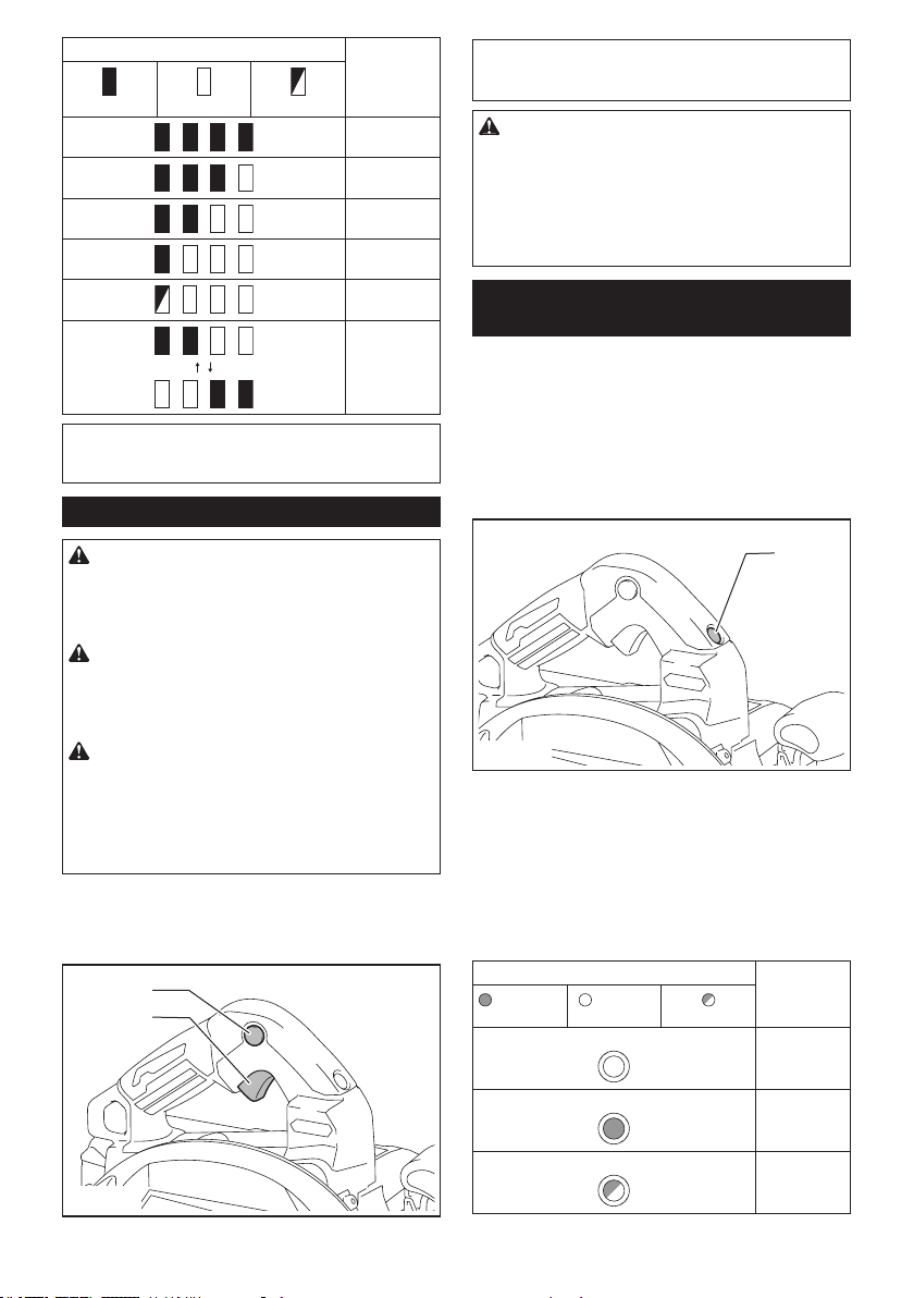
31 ESPAÑOL
Luces indicadoras Capacidad
restante
Iluminadas Apagadas Parpadeando
75% a 100%
50% a 75%
25% a 50%
0% a 25%
Cargar la
batería.
La batería
pudo haber
funcionado
mal.
NOTA: Dependiendo de las condiciones de uso y
la temperatura ambiente, la indicación podrá diferir
ligeramente de la capacidad real.
Accionamiento del interruptor
ADVERTENCIA: Antes de insertar el car-
tucho de batería en la herramienta, compruebe
siempre y cerciórese de que el gatillo interruptor
se acciona debidamente y que vuelve a la posi-
ción “OFF” (apagado) cuando lo suelta.
ADVERTENCIA:
NUNCA inhabilite el botón de
desbloqueo manteniéndolo presionado con cinta adhe-
siva o mediante otro método. El uso de un interruptor con
un botón de desbloqueo inhabilitado puede ocasionar una
operación accidental y lesiones personales graves.
ADVERTENCIA:
NUNCA use la herramienta si
se activa simplemente al jalar el gatillo interruptor sin
que haya presionado el botón de desbloqueo. El uso de
un interruptor que requiere reparación puede ocasionar una
operación accidental y lesiones personales graves. Lleve la
herramienta a un centro de servicio Makita para las repara-
ciones apropiadas ANTES de continuar su uso.
El botón de desbloqueo es suministrado para evitar jalar
accidentalmente el gatillo interruptor. Para arrancar la herra-
mienta, presione el botón de desbloqueo y jale el gatillo
interruptor. Para detenerla, suelte el gatillo interruptor.
2
1
► 1. Gatillo interruptor 2. Botón de desbloqueo
AVISO: No jale fuertemente el gatillo interruptor
sin presionar el botón de desbloqueo. Esto podría
dañar el interruptor.
PRECAUCIÓN: La herramienta comenzará
a frenar la rotación del disco de la sierra circular
inmediatamente después de haber soltado el
gatillo interruptor. Sostenga la herramienta rme-
mente para responder a la reacción del freno al
soltar el gatillo interruptor. Una reacción repentina
podría hacer caer la herramienta de su mano y oca-
sionar una lesión personal.
Función de cambio de velocidad
automática
Esta herramienta cuenta con “modo de alta velocidad” y
“modo de alta torsión”.
La herramienta cambia automáticamente el modo de
operación en función de la carga de trabajo. Cuando la
carga de trabajo sea baja, la herramienta funcionará en
“modo de alta velocidad” para una operación de corte
más rápida. Cuando la carga de trabajo sea alta, la
herramienta funcionará en “modo de alta torsión” para
una operación de corte con mayor potencia.
1
► 1. Indicador de modo
El indicador de modo se encenderá en verde cuando
la herramienta esté funcionando en “modo de alta
torsión”.
Si la herramienta es operada con una carga excesiva,
el indicador de modo comenzará a parpadear en verde.
El indicador de modo dejará de parpadear y luego
se encenderá o se apagará al reducir la carga en la
herramienta.
Estado del indicador de modo Modo de
operación
Encendido Apagado
Parpadeando
Modo de alta
velocidad
Modo de alta
torsión
Alerta de
sobrecarga
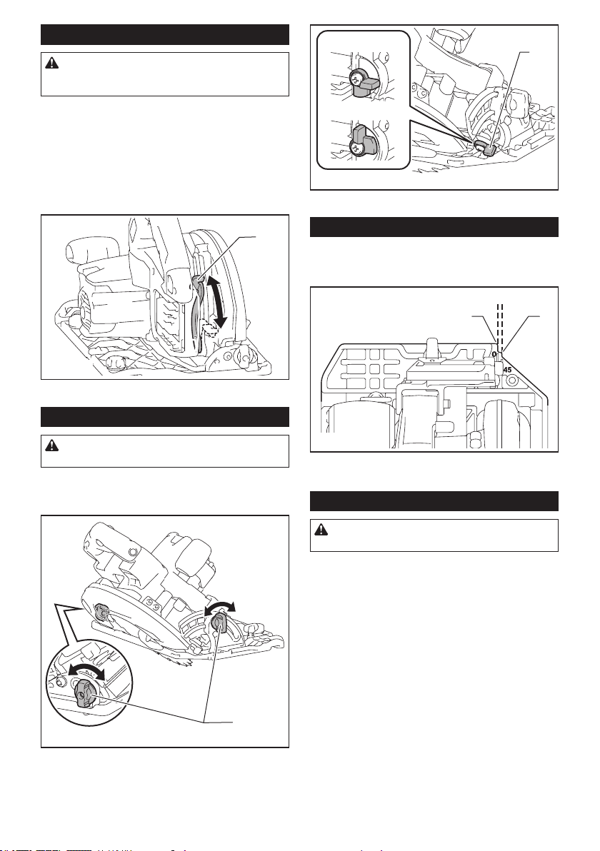
32 ESPAÑOL
Ajuste de la profundidad de corte
PRECAUCIÓN: Después de ajustar la pro-
fundidad de corte, siempre apriete la palanca
rmemente.
Aoje la palanca en la guía de profundidad y mueva la
base hacia arriba o hacia abajo. En la profundidad de
corte deseada, je la base apretando la palanca.
Para obtener cortes más limpios y seguros, ajuste la profun-
didad de corte de forma que no sobresalga más de un diente
del disco por debajo de la pieza de trabajo. El uso de una
profundidad de corte adecuada ayuda a reducir la posibilidad
de que se produzca un peligroso RETROCESO BRUSCO que
pueda ocasionar lesiones personales.
1
► 1. Palanca
Corte en bisel
PRECAUCIÓN:
Después de ajustar el ángulo de
bisel, apriete siempre los tornillos de jación con rmeza.
Aoje los tornillos de jación. Ajuste el ángulo deseado
inclinando según corresponda, después apriete los
tornillos de jación rmemente.
1
► 1. Tornillo de jación
Use el tope cuando haga cortes precisos de ángulos de
45°. Gire completamente el tope como se muestra en la
ilustración, según el corte de bisel de 0°- 45° o 0°- 48°.
1
0° - 45°
0° - 48°
► 1. Tope
Guía visual
Para cortes rectos, alinee la posición de 0° en la parte
delantera de la base con su línea de corte. Para cortes
en bisel a 45°, alinee la posición de 45° con la misma.
1
2
► 1. Línea de corte (posición de 0°) 2. Línea de corte
(posición de 45°)
Encendido de la lámpara
PRECAUCIÓN: No mire a la luz ni vea a la
fuente de luz directamente.
Para encender la lámpara sin poner en marcha la herra-
mienta, jale el gatillo interruptor sin oprimir el botón de
desbloqueo.
Para encender la lámpara con la herramienta puesta
en marcha, presione y mantenga oprimido el botón de
desbloqueo y jale el gatillo interruptor.
La lámpara se apagará 10 segundos después tras
haber soltado el gatillo interruptor.
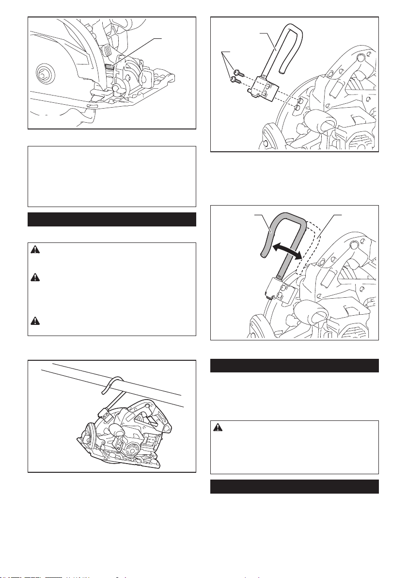
33 ESPAÑOL
1
► 1. Lámpara
NOTA: Utilice un paño seco para quitar la suciedad
de la lente de la lámpara. Tenga cuidado de no rayar
la lente de la lámpara ya que la iluminación podría
disminuir.
NOTA: Cuando la herramienta se sobrecalienta, la
luz parpadea durante un minuto. En este caso, deje
enfriar la herramienta antes de usarla de nuevo.
Gancho
Accesorio opcional
PRECAUCIÓN: Retire siempre la batería
cuando vaya a colgar la herramienta con el
gancho.
PRECAUCIÓN: Nunca enganche la herra-
mienta en lugares elevados o potencialmente
inestables, como sobre las supercies. De lo
contrario, la herramienta podría perder el equilibro y
caerse.
PRECAUCIÓN: No jale la herramienta hacia
abajo cuando esté colgada.
El gancho resulta útil para colgar temporalmente la
herramienta.
Fije el gancho con los tornillos tal como se muestra en
la ilustración.
1
2
► 1. Gancho 2. Tornillo
Para usar el gancho, simplemente gírelo hasta que
quede trabado en la posición abierta.
Cuando no vaya a utilizar el gancho, siempre gírelo
hasta que quede trabado en la posición cerrada.
1 2
► 1. Posición abierta 2. Posición cerrada
Freno eléctrico
La herramienta está equipada con un freno eléctrico
para el disco. Si la herramienta falla constantemente en
la detención rápida del disco de la sierra circular tras
soltar la palanca del interruptor, lleve la herramienta a
mantenimiento a un centro de servicio Makita.
PRECAUCIÓN: El sistema de frenado
del disco no es un sustituto del protector del
disco. NUNCA UTILICE LA HERRAMIENTA SI
EL PROTECTOR DEL DISCO NO FUNCIONA. EL
HACERLO PODRÍA OCASIONAR UNA LESIÓN
PERSONAL.
Función eléctrica
Las herramientas equipadas con funciones electrónicas
son fáciles de operar gracias a la(s) característica(s) a
continuación.
Función de arranque suave
Permite el arranque suave gracias a que reduce el
impacto de encendido.
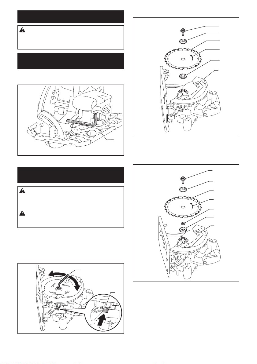
34 ESPAÑOL
MONTAJE
PRECAUCIÓN: Asegúrese siempre de que la
herramienta esté apagada y el cartucho de batería
haya sido extraído antes de realizar cualquier
trabajo en la misma.
Almacenamiento de la llave Allen
(hexagonal)
Cuando no la utilice, guarde la llave hexagonal como se
muestra en la gura para evitar que se pierda.
1
► 1. Llave Allen (hexagonal)
Extracción o instalación del disco
de la sierra circular
PRECAUCIÓN: Asegúrese de que el disco
de la sierra circular esté instalado con los dientes
orientados hacia arriba en la parte delantera de la
herramienta.
PRECAUCIÓN: Utilice solamente la llave
Makita para instalar o extraer el disco de la sierra
circular.
Para extraer el disco de la sierra circular, presione el
bloqueo del eje por completo de forma que el disco de
la sierra circular no pueda girar y use la llave hexagonal
para aojar el perno hexagonal. Luego retire el perno
hexagonal, la brida exterior, el disco de la sierra circular
y el anillo (especíco del país).
2
1
4
3
► 1. Bloqueo del eje 2. Llave hexagonal 3. Aojar
4. Apretar
Para la herramienta sin anillo
1
2
3
4
5
6
► 1. Perno hexagonal 2. Brida exterior 3. Disco de
la sierra circular 4. Flecha en el disco de la sierra
circular 5. Brida interior 6. Flecha en la herramienta
Para la herramienta con anillo
1
2
3
4
5
7
6
► 1. Perno hexagonal 2. Brida exterior 3. Disco de la
sierra circular 4.
Flecha en el disco de la sierra circula
r
5. Anillo 6. Brida interior 7. Flecha en la herramienta
Para instalar el disco de la sierra circular, siga el proce-
dimiento de extracción en orden inverso.
Alinee la dirección de la echa en el disco con la echa
en la herramienta.
Instale la brida interior con su lado ahuecado orientado
hacia afuera sobre el eje de montaje y luego coloque el
disco de la sierra (con el anillo puesto si es necesario),
la brida exterior y el perno hexagonal.
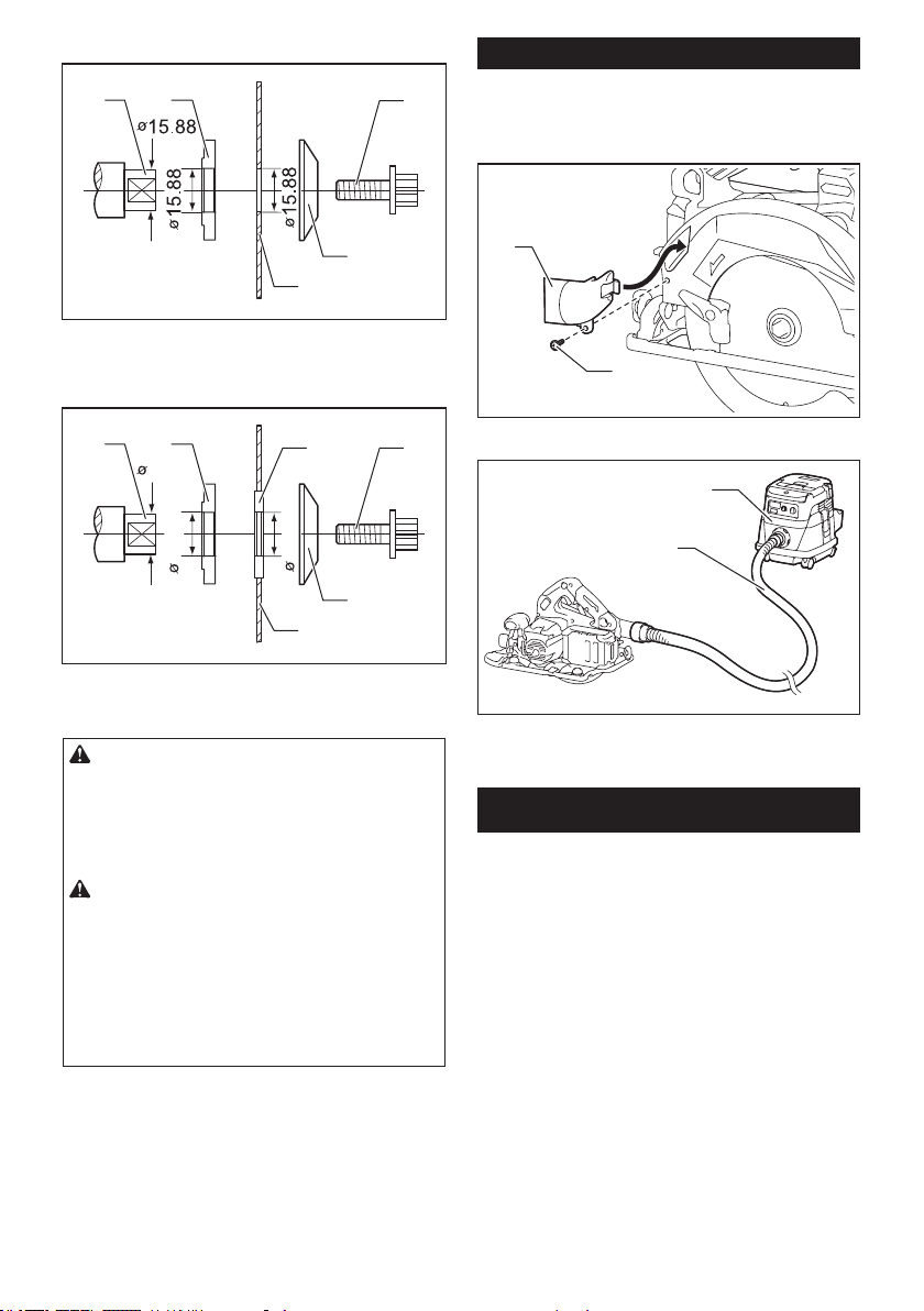
35 ESPAÑOL
Para la herramienta sin anillo
12
3
4
5
► 1. Eje de montaje 2. Brida interior 3. Disco de la
sierra circular 4. Brida exterior 5. Perno hexagonal
Para la herramienta con anillo
12
3
4
5
6
15.88
15.88
15.88
► 1. Eje de montaje 2. Brida interior 3. Disco de la
sierra circular 4. Brida exterior 5. Perno hexagonal
6. Anillo
ADVERTENCIA: ASEGÚRESE DE APRETAR
FIRMEMENTE EL PERNO HEXAGONAL EN EL
SENTIDO DE LAS MANECILLAS DEL RELOJ.
Asimismo, tenga cuidado de no apretar el perno
con demasiada fuerza. Si su mano llega a resba-
larse de la llave hexagonal podría ocasionarle una
lesión.
ADVERTENCIA: Si se requiere un anillo para
montar el disco sobre el eje, asegúrese siempre
de instalar el anillo correcto para el oricio del
eje del disco que desea utilizar entre las bridas
interior y exterior. El uso de un anillo incorrecto
para el oricio del eje puede ocasionar un montaje
inadecuado del disco provocando que éste se mueva
y vibre excesivamente, pudiendo causar a su vez la
pérdida de control durante la operación y lesiones
personales graves.
Limpieza del protector del disco
Al cambiar el disco de la sierra circular, asegúrese de
limpiar también el aserrín acumulado en los protectores
superior e inferior del disco, tal como se indica en la
sección de Mantenimiento. Sin embargo, esta tarea no
sustituye la necesidad de revisar la operación del pro-
tector inferior antes de cada uso.
Conexión de una aspiradora
Cuando desee realizar una operación de corte limpia,
conecte una aspiradora Makita a su herramienta.
Conecte la manguera de la aspiradora a la boquilla
para polvo tal como se muestra en la gura.
1
2
► 1. Boquilla para polvo 2. Tornillo
1
2
► 1. Manguera 2. Aspiradora
OPERACIÓN
Esta herramienta está diseñada para cortar productos
de madera. Con los discos de la sierra circulares apro-
piados y originales de Makita también se pueden cortar
los siguientes tipos de materiales:
• Productos de aluminio
Consulte nuestro sitio web o póngase en contacto con
su distribuidor local de Makita para información sobre
los discos de sierra circulares correctos para emplearse
con el material que se va a cortar.
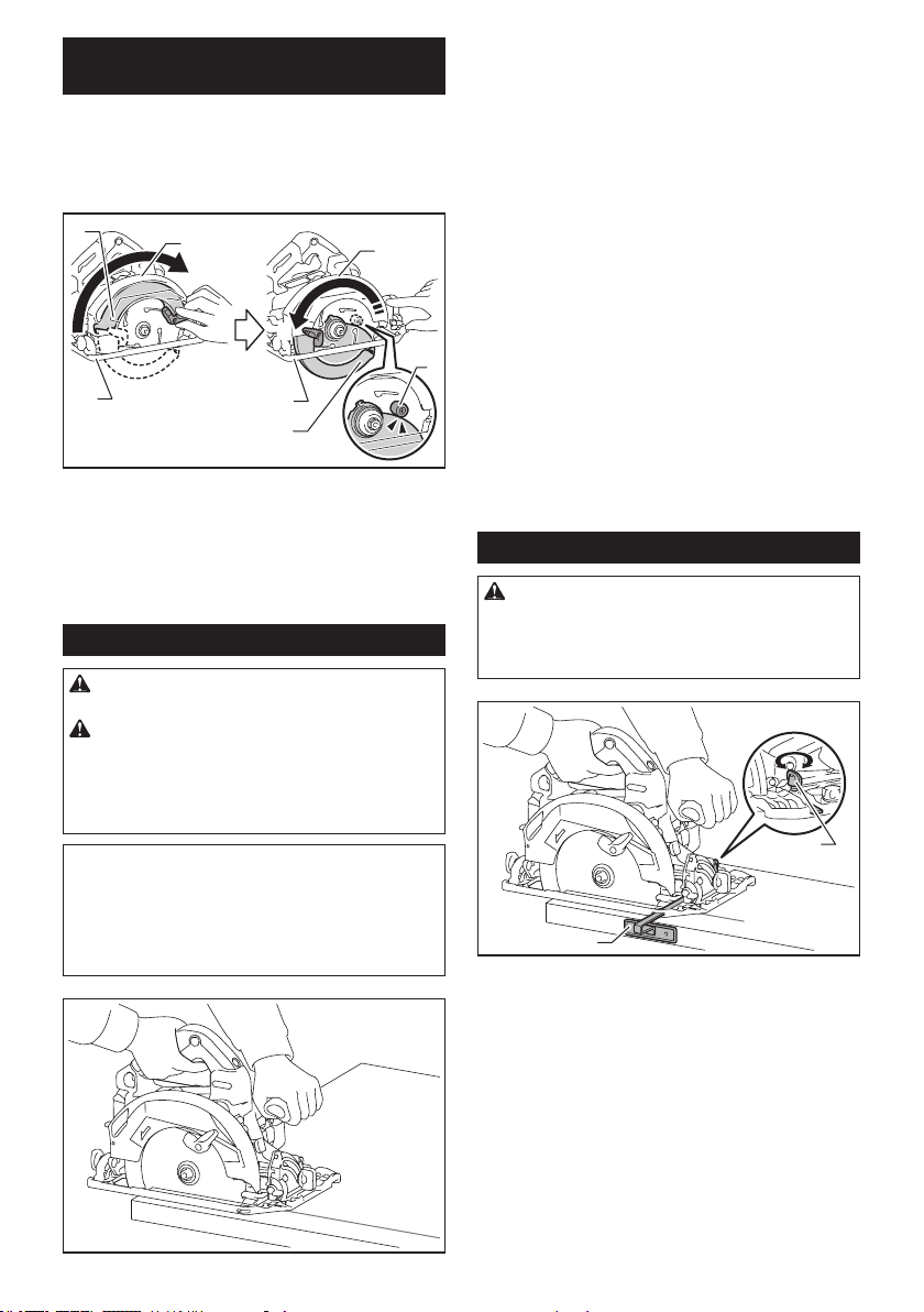
36 ESPAÑOL
Vericación de la función del
protector del disco
Fije el ángulo de bisel a 0° y luego retraiga manual-
mente el protector inferior hasta el nal y suéltelo. El
protector inferior funcionará adecuadamente si:
—
se retrae por encima de la base sin ningún obstáculo; y
—
regresa automáticamente y hace contacto con el tope.
1
1
2
2
3
4
5
6
3
► 1. Protector superior 2. Protector inferior 3. Base
4. Tope 5. Abrir 6. Cerrar
Si el protector inferior no funciona adecuadamente, verique si se
acumuló aserrín dentro del protector superior e inferior. Si el protector
inferior no está funcionando adecuadamente, incluso después de
retirar el polvo, lleve su herramienta a un centro de servicio Makita
para que le den servicio.
Operación de corte
PRECAUCIÓN: Utilice una máscara contra
polvo cuando realice la operación de corte.
PRECAUCIÓN: Asegúrese de mover la
herramienta hacia adelante en línea recta y sua-
vemente. El forzar o torcer la herramienta producirá
un sobrecalentamiento del motor y un peligroso
retroceso brusco, posiblemente causando lesiones
graves.
NOTA: Cuando el cartucho de batería está frío, la
herramienta puede no funcionar a su capacidad com-
pleta. En ese momento use la herramienta, por ejem-
plo, para cortes ligeros durante algún tiempo hasta
que el cartucho de batería se caliente hasta alcanzar
la temperatura ambiente. De este modo, la herra-
mienta podrá funcionar a su capacidad completa.
Sujete rmemente la herramienta. La herramienta está
provista de empuñadura delantera y mango trasero.
Utilice ambos para sujetar de forma óptima la herra-
mienta. Si ambas manos están sujetando la sierra,
éstas no podrán ser cortadas por el disco de la sierra
circular. Coloque la base sobre la pieza de trabajo a
cortar sin que el disco de la sierra circular haga con-
tacto alguno. Luego encienda la herramienta y espere
a que el disco de la sierra circular alcance su velocidad
completa. Ahora simplemente mueva la herramienta
hacia adelante sobre la supercie de la pieza de tra-
bajo, manteniéndola plana y avanzando suavemente
hasta completar el corte.
Para obtener cortes limpios, mantenga la línea de corte
recta y la velocidad de avance uniforme. Si se desvía
de la línea de corte prevista, no intente girar ni forzar
la herramienta para hacerla volver a la línea de corte.
Esta acción podría atorar el disco de la sierra circular
y ocasionar un peligroso retroceso brusco y posibles
lesiones graves. Suelte el interruptor, espere hasta
que el disco de la sierra circular se detenga y después
retire la herramienta. Vuelva a alinear la herramienta en
una nueva línea de corte y comience el corte otra vez.
Hay que evitar posturas en las que el operador quede
expuesto a las astillas y el aserrín expulsados de la
sierra. Use protección para los ojos para poder evitar
las lesiones.
Tope lateral de corte (regla guía)
PRECAUCIÓN: Asegúrese de que el tope
lateral de corte esté rmemente instalado en la
posición correcta antes del uso. Un acoplamiento
incorrecto podría ocasionar retrocesos bruscos
peligrosos.
1
2
► 1. Tope lateral de corte (regla guía) 2. Tornillo de
jación
El útil tope lateral de corte le permite hacer cortes rec-
tos extra precisos. Simplemente deslice el tope lateral
de corte para que quede ceñidamente ajustado contra
el costado de la pieza de trabajo y fíjelo con el tornillo
en la parte delantera de la base. Con ello también se
pueden hacer cortes repetidos de anchura uniforme.
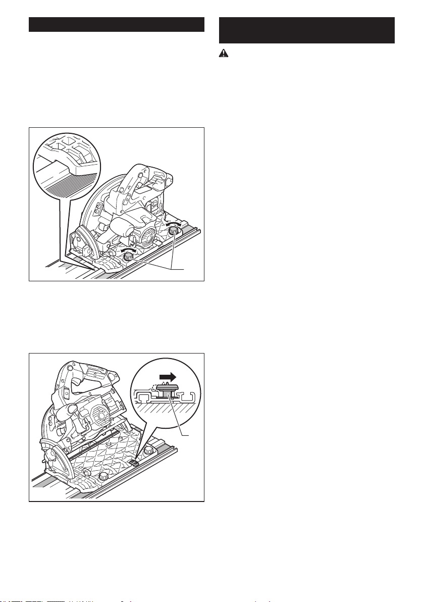
37 ESPAÑOL
Carril guía
Accesorio opcional
Coloque la herramienta en el extremo trasero del carril
guía. Gire los dos tornillos de ajuste sobre la base de
la herramienta de tal forma que ésta se deslice suave
y libremente. Sujete tanto la empuñadura delantera
como el mango trasero de la herramienta rmemente.
Encienda la herramienta y corte el protector contra
astillas a lo largo de toda la longitud con una pasada.
El borde del protector contra astillas ahora corresponde
con el borde de corte.
1
► 1. Tornillos de ajuste
Cuando realice cortes en bisel con el carril guía, utilice
la palanca deslizable para evitar que la herramienta se
caiga.
Mueva la palanca deslizable sobre la base de la herra-
mienta en la dirección de la echa de manera que
encaje en la ranura del corte al ras en el carril guía.
1
► 1. Palanca deslizable
Conexión con cordeles (correas de
atadura)
Advertencias de seguridad especícas para uso
en alturas
Lea todas las advertencias de seguridad e instruc-
ciones. El no seguir las advertencias e instrucciones
podría ocasionar lesiones graves.
1. Mantenga siempre la herramienta atada
cuando trabaje “en alturas”. La longitud
máxima del cordel es de 2 m (6,5 ft).
La altura de caída máxima permisible para
el cordel de seguridad (correa de amarre) no
deberá superar los 2 m (6,5 ft).
2. Use únicamente con cordeles apropiados para
este tipo de herramienta y clasicados para al
menos 7,0 kg (15,4 lbs).
3. No ancle el cordel de la herramienta a nada
en su cuerpo o a componentes móviles. Ancle
el cordel de la herramienta a una estructura
rígida que pueda soportar las fuerzas de una
herramienta en caída.
4. Asegúrese de que el cordel esté debidamente
asegurado de cada extremo previo al uso.
5. Inspeccione la herramienta y el cordel antes
de cada uso para ver que no tengan daños y
que funcionen correctamente (incluyendo la
tela y las puntadas). No los utilice si presentan
daños o no funcionan correctamente.
6. No envuelva cordeles alrededor de bordes
losos o ásperos ni permita que estos entren
en contacto con ellos.
7. Asegure el otro extremo del cordel fuera del
área de trabajo de manera que la herramienta
en caída esté rmemente sujetada.
8. Fije el cordel de forma que la herramienta se
mueva lejos del operador en caso de que esta
se caiga. Las herramientas en caída se balan-
cean en el cordel, lo que puede ocasionar lesio-
nes o la pérdida del equilibrio.
9. No la utilice cerca de piezas móviles o maqui-
naria funcionando. El hacerlo podría ocasionar
riesgo de choque o enredo.
10. No transporte la herramienta sujetándola del
dispositivo de atadura o el cordel.
11. Cargue la herramienta únicamente entre sus
manos mientras mantenga bien el equilibrio.
12. No ate cordeles a la herramienta de manera
que evite que los protectores, interruptores o
bloqueos funcionen correctamente.
13. Evite enredarse en el cordel.
14. Mantenga el cordel alejado del área de corte de
la herramienta.
15. Use mosquetones de tipo multiacción y de tipo
seguro de rosca. No use mosquetones de tipo
acción única con gancho de resorte.
16. En caso de que la herramienta llegue a caerse,
esta debe etiquetarse, sacarse de servicio y
ser inspeccionada por una fábrica o centro de
servicio autorizado Makita.
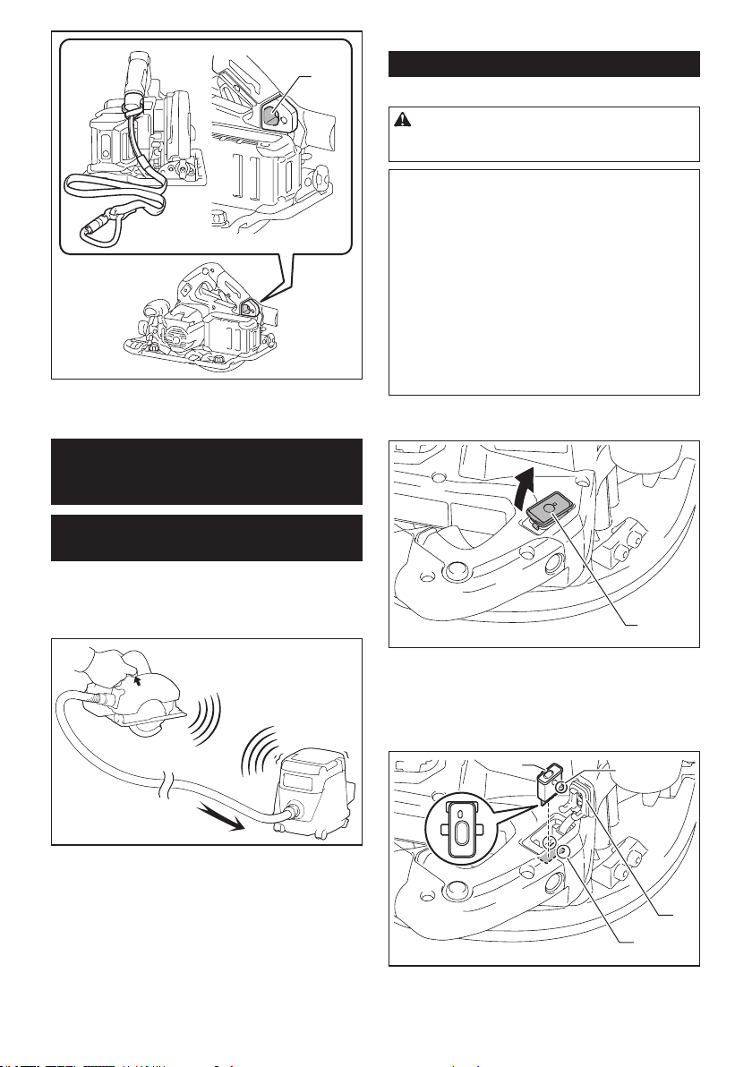
38 ESPAÑOL
1
► 1. Oricio para el cordel (correa de atadura)
FUNCIÓN DE ACTIVACIÓN
INALÁMBRICA
Lo que puede hacer con la función
de activación inalámbrica
La función de activación inalámbrica permite una operación
limpia y cómoda. Si conecta a la herramienta una aspiradora
compatible, podrá hacer que ésta funcione automáticamente
al activar el interruptor de la herramienta.
Para hacer uso de la función de activación inalámbrica,
tenga preparado lo siguiente:
• Una unidad inalámbrica (accesorios opcionales)
• Una aspiradora compatible con la función de
activación inalámbrica
A continuación se presenta la descripción general del
ajuste de la función de activación inalámbrica. Consulte
cada sección para ver los procedimientos a detalle.
1. Instalación de la unidad inalámbrica
2. Registro de la herramienta para la aspiradora
3. Inicio de la función de activación inalámbrica
Instalación de la unidad inalámbrica
Accesorio opcional
PRECAUCIÓN: Coloque la herramienta sobre
una supercie plana y estable cuando vaya a
instalar la unidad inalámbrica.
AVISO: Limpie el polvo y la suciedad en la herra-
mienta antes de instalar la unidad inalámbrica.
El polvo o la suciedad podrían causar una avería
si llegan a introducirse en la ranura de la unidad
inalámbrica.
AVISO: Para evitar una avería a causa de la elec-
tricidad estática, toque un material de descarga
de electricidad estática, tal como una pieza metá-
lica de la herramienta antes de levantar la unidad
inalámbrica.
AVISO: Cuando vaya a instalar la unidad inalám-
brica, asegúrese siempre de que ésta sea inser-
tada en la dirección correcta y que la tapa esté
completamente cerrada.
1. Abra la tapa en la herramienta tal como se mues-
tra en la ilustración.
1
► 1. Tapa
2. Inserte la unidad inalámbrica en la ranura y luego
cierre la tapa.
Cuando inserte la unidad inalámbrica, alinee las partes
salientes con las partes cóncavas en la ranura.
2
1
3
4
► 1. Unidad inalámbrica 2. Parte saliente 3. Tapa
4. Parte cóncava
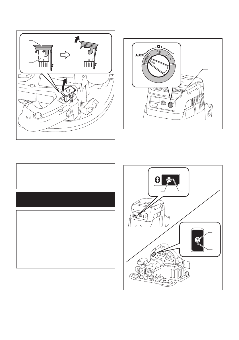
39 ESPAÑOL
Cuando extraiga la unidad inalámbrica, abra la tapa
lentamente. Los ganchos en la parte posterior de la
tapa levantarán la unidad inalámbrica mientras usted
jala hacia arriba la tapa.
1
2
3
► 1. Unidad inalámbrica 2. Gancho 3. Tapa
Una vez extraída la unidad inalámbrica, guárdela en el
estuche suministrado o en un contenedor libre de elec-
tricidad estática.
AVISO: Use siempre los ganchos en la parte
posterior de la tapa cuando extraiga la unidad
inalámbrica. Si los ganchos no sujetan la unidad
inalámbrica, cierre la tapa por completo y vuelva a
abrirla lentamente.
Registro de la herramienta para la
aspiradora
NOTA: Para el registro de la herramienta, se requiere
una aspiradora Makita compatible con la función de
activación inalámbrica.
NOTA: Termine de instalar la unidad inalámbrica en
la herramienta antes de comenzar con el registro de
la herramienta.
NOTA: Durante el registro de la herramienta, no jale
el gatillo interruptor ni active el interruptor de encen-
dido en la aspiradora.
NOTA: Consulte también el manual de instrucciones
de la aspiradora.
Si desea activar la aspiradora junto con el interruptor de la
herramienta, termine antes con el registro de la herramienta.
1.
Instale las baterías en la aspiradora y en la herramienta.
2. Ajuste el interruptor de modo en espera en la aspi-
radora en “AUTO”.
1
► 1. Interruptor de modo en espera
3. Oprima el botón de activación inalámbrica en la
aspiradora durante 3 segundos hasta que la luz indica-
dora de activación inalámbrica parpadee en verde. Y
luego oprima el botón de activación inalámbrica en la
herramienta de la misma manera.
2
1
2
1
► 1. Botón de activación inalámbrica 2. Luz indica-
dora de activación inalámbrica
Si la aspiradora y la herramienta han sido conectadas
exitosamente, las luces indicadoras de activación ina-
lámbrica se encenderán en verde durante 2 segundos y
comenzarán a parpadear en azul.
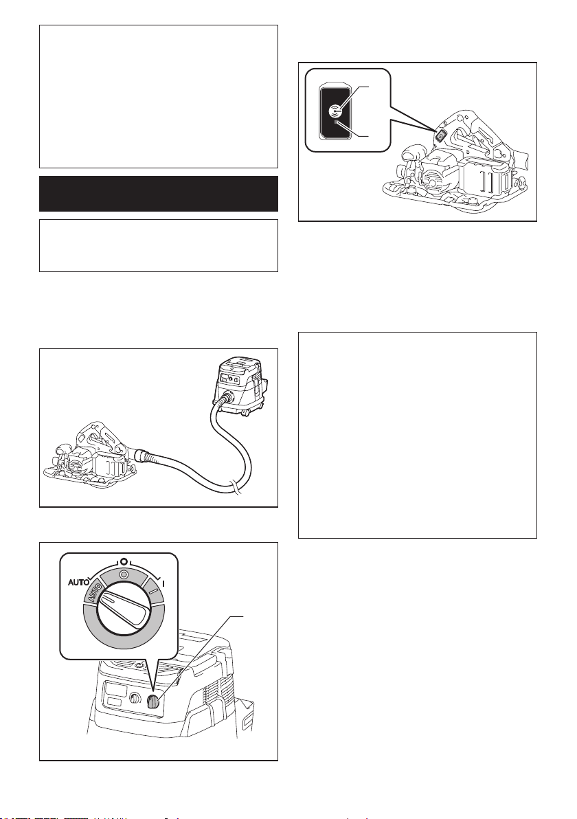
40 ESPAÑOL
NOTA: Las luces indicadoras de activación inalám-
brica terminarán parpadeando en verde después de
un lapso de 20 segundos. Oprima el botón de acti-
vación inalámbrica en la herramienta mientras la luz
indicadora de activación inalámbrica en la aspiradora
esté parpadeando. Si la luz indicadora de activación
inalámbrica no parpadea en verde, oprima el botón
de activación inalámbrica durante un lapso breve y
vuelva a mantenerlo oprimido.
NOTA: Cuando realice dos o más registros de la
herramienta para una aspiradora, termine el registro
de la herramienta de uno en uno.
Inicio de la función de activación
inalámbrica
NOTA: Termine con el registro de la herramienta para
la aspiradora antes de la activación inalámbrica.
NOTA: Consulte también el manual de instrucciones
de la aspiradora.
Después de registrar una herramienta en la aspiradora,
esta última se activará automáticamente junto con el
interruptor de la herramienta.
1. Instale la unidad inalámbrica en la herramienta.
2.
Conecte la manguera de la aspiradora a la herramienta.
3. Ajuste el interruptor de modo en espera en la aspi-
radora en “AUTO”.
1
► 1. Interruptor de modo en espera
4. Oprima el botón de activación inalámbrica en la
herramienta durante un lapso breve. La luz indicadora
de activación inalámbrica parpadeará en azul.
1
2
► 1. Botón de activación inalámbrica 2. Luz indica-
dora de activación inalámbrica
5. Jale el gatillo interruptor de la herramienta.
Verique que la aspiradora funcione mientras jala el
gatillo interruptor.
Para detener la activación inalámbrica de la aspira-
dora, oprima el botón de activación inalámbrica en la
herramienta.
NOTA: La luz indicadora de activación inalámbrica en
la herramienta dejará de parpadear en azul cuando
no haya operación durante 2 horas. En este caso,
ajuste el interruptor de modo en espera en la aspi-
radora en “AUTO” y oprima el botón de activación
inalámbrica en la herramienta nuevamente.
NOTA: La aspiradora funcionará/detendrá con un
retraso. Existirá un desfase cuando la aspiradora
detecte la activación del interruptor de la herramienta.
NOTA: La distancia de transmisión de la unidad
inalámbrica podrá variar en función del lugar y las
circunstancias de los alrededores.
NOTA: Cuando dos o más herramientas estén
registradas en una aspiradora, esta última podrá
comenzar a funcionar incluso si usted no jala el gatillo
interruptor debido a que otro usuario está utilizando
la función de activación inalámbrica.
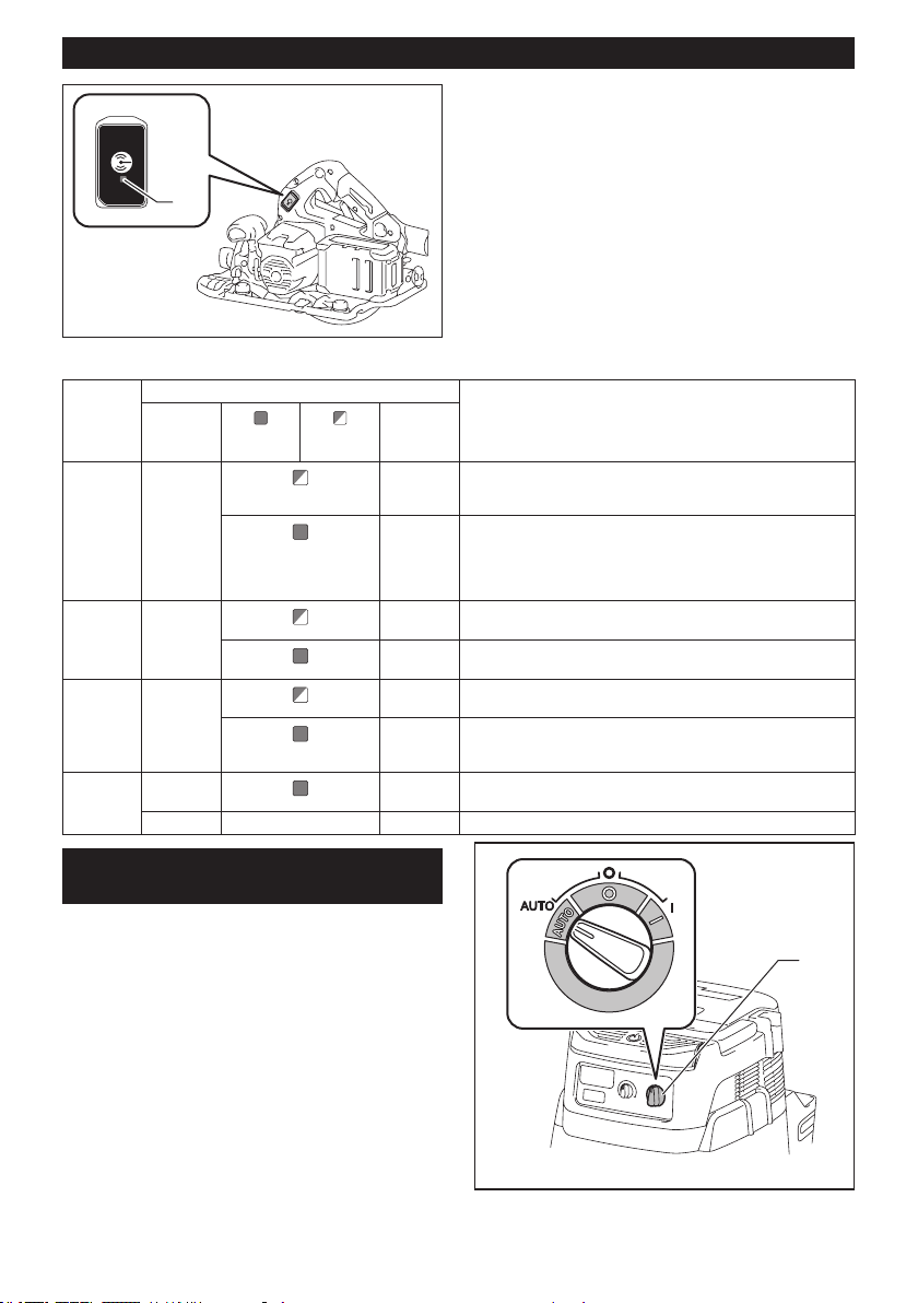
41 ESPAÑOL
Descripción del estado de la luz indicadora de activación inalámbrica
1
► 1. Luz indicadora de activación inalámbrica
La luz indicadora de activación inalámbrica muestra
el estado de la función de activación inalámbrica.
Consulte la tabla a continuación para ver qué signica
el estado de la luz indicadora.
Estado Luz indicadora de activación inalámbrica Descripción
Color
Encendida
Parpa-
deando
Duración
En espera Azul
2 horas La activación inalámbrica de la aspiradora está disponible. La
luz se apagará automáticamente cuando no se realice ninguna
operación durante 2 horas.
Cuando
la herra-
mienta
está fun-
cionando.
La activación inalámbrica de la aspiradora está disponible y la
herramienta está funcionando.
Registro
de la
herramienta
Verde
20
segundos
Ya se puede realizar el registro de la herramienta. Esperando el
registro por parte de la aspiradora.
2
segundos
El registro de la herramienta ha terminado. La luz indicadora de
activación inalámbrica comenzará a parpadear en azul.
Cancela-
ción del
registro
de la
herramienta
Rojo
20
segundos
Ya se puede cancelar el registro de la herramienta. Esperando la
cancelación por parte de la aspiradora.
2
segundos
La cancelación del registro de la herramienta ha terminado. La
luz indicadora de activación inalámbrica comenzará a parpadear
en azul.
Otros Rojo
3
segundos
La energía es suministrada a la unidad inalámbrica y la función
de activación inalámbrica está arrancando.
Apagada - - La activación inalámbrica de la aspiradora se ha detenido.
Cancelación del registro de la
herramienta para la aspiradora
Realice el siguiente procedimiento para cancelar el
registro de la herramienta para la aspiradora.
1. Instale las baterías en la aspiradora y en la
herramienta.
2. Ajuste el interruptor de modo en espera en la aspi-
radora en “AUTO”.
1
► 1. Interruptor de modo en espera
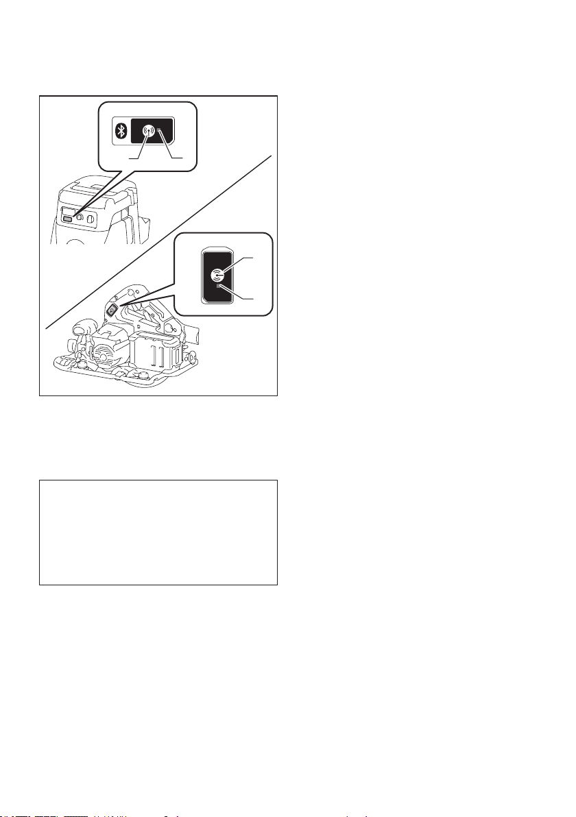
42 ESPAÑOL
3. Oprima el botón de activación inalámbrica en la
aspiradora durante 6 segundos. La luz indicadora de
activación inalámbrica parpadeará en verde y luego se
pondrá en rojo. Después de eso, oprima el botón de
activación inalámbrica en la herramienta de la misma
manera.
2
1
2
1
► 1. Botón de activación inalámbrica 2. Luz indica-
dora de activación inalámbrica
Si la cancelación se realiza exitosamente, las luces
indicadoras de activación inalámbrica se encenderán
en rojo durante 2 segundos y comenzarán a parpadear
en azul.
NOTA: Las luces indicadoras de activación inalám-
brica terminarán parpadeando en rojo después de un
lapso de 20 segundos. Oprima el botón de activación
inalámbrica en la herramienta mientras la luz indi-
cadora de activación inalámbrica en la aspiradora
esté parpadeando. Si la luz indicadora de activación
inalámbrica no parpadea en rojo, oprima el botón
de activación inalámbrica durante un lapso breve y
vuelva a mantenerlo oprimido.

43 ESPAÑOL
Detección y solución de problemas para la función de activación inalámbrica
Antes de solicitar alguna reparación, primero realice una inspección por su cuenta. Si detecta algún problema que
no esté explicado en el manual, no intente desensamblar la herramienta. En vez de esto, solicite la reparación a un
centro de servicio autorizado de Makita, usando siempre piezas de repuesto Makita.
Estado de la anomalía Causa probable (avería) Remedio
La luz indicadora de activación ina-
lámbrica no enciende/parpadea.
La unidad inalámbrica no está instalada
en la herramienta.
La unidad inalámbrica está instalada
incorrectamente en la herramienta.
Instale la unidad inalámbrica correctamente.
La terminal de la unidad inalámbrica y/o
la ranura está sucia.
Retire con cuidado el polvo y la suciedad en la
terminal de la unidad inalámbrica y limpie la ranura.
El botón de activación inalámbrica en la
herramienta no se ha oprimido.
Oprima el botón de activación inalámbrica en la
herramienta durante un lapso breve.
El interruptor de modo en espera en la
aspiradora no está ajustado en “AUTO”.
Ajuste el interruptor de modo en espera en la
aspiradora en “AUTO”.
No hay suministro de energía. Suministre energía a la herramienta y a la
aspiradora.
No se puede terminar/cancelar
el registro de la herramienta
exitosamente.
La unidad inalámbrica no está instalada
en la herramienta.
La unidad inalámbrica está instalada
incorrectamente en la herramienta.
Instale la unidad inalámbrica correctamente.
La terminal de la unidad inalámbrica y/o
la ranura está sucia.
Retire con cuidado el polvo y la suciedad en la
terminal de la unidad inalámbrica y limpie la ranura.
El interruptor de modo en espera en la
aspiradora no está ajustado en “AUTO”.
Ajuste el interruptor de modo en espera en la
aspiradora en “AUTO”.
No hay suministro de energía. Suministre energía a la herramienta y a la
aspiradora.
Operación incorrecta Oprima el botón de activación inalámbrica durante
un lapso breve y realice los procedimientos de
registro/cancelación de la herramienta nuevamente.
La herramienta y la aspiradora están
lejos una de la otra (fuera del rango de
transmisión).
Acerque más la herramienta a la aspiradora. La
distancia máxima de transmisión es de aproxima-
damente 10 m, pero puede variar en función de las
circunstancias.
Antes de terminar el registro/cancela-
ción de la herramienta;
- el gatillo interruptor en la herramienta
se ha jalado; o
- el botón de encendido en la aspira-
dora está activado.
Oprima el botón de activación inalámbrica durante
un lapso breve y realice los procedimientos de
registro/cancelación de la herramienta nuevamente.
Los procedimientos de registro para
la herramienta o aspiradora no se han
terminado.
Realice los procedimientos de registro tanto para
la herramienta como para la aspiradora al mismo
tiempo.
La perturbación radioeléctrica generada
por otros aparatos que emiten ondas de
radio de alta intensidad.
Mantenga la herramienta y la aspiradora lejos de
aparatos tales como dispositivos Wi-Fi y hornos de
microondas.
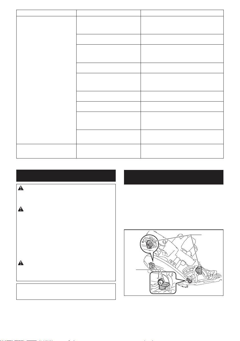
44 ESPAÑOL
Estado de la anomalía Causa probable (avería) Remedio
La aspiradora no funciona junto con
el interruptor de la herramienta.
La unidad inalámbrica no está instalada
en la herramienta.
La unidad inalámbrica está instalada
incorrectamente en la herramienta.
Instale la unidad inalámbrica correctamente.
La terminal de la unidad inalámbrica y/o
la ranura está sucia.
Retire con cuidado el polvo y la suciedad en la
terminal de la unidad inalámbrica y limpie la ranura.
El botón de activación inalámbrica en la
herramienta no se ha oprimido.
Oprima el botón de activación inalámbrica durante
un lapso breve y asegúrese de que la luz indicadora
de activación inalámbrica esté parpadeando en
azul.
El interruptor de modo en espera en la
aspiradora no está ajustado en “AUTO”.
Ajuste el interruptor de modo en espera en la
aspiradora en “AUTO”.
Más de 10 herramientas están registra-
das en la aspiradora.
Vuelva a realizar el registro de la herramienta.
Si más de 10 herramientas están registradas en la
aspiradora, la herramienta registrada al principio se
cancelará automáticamente.
La aspiradora borró todos los registros
de la herramienta.
Vuelva a realizar el registro de la herramienta.
No hay suministro de energía. Suministre energía a la herramienta y a la
aspiradora.
La herramienta y la aspiradora están
lejos una de la otra (fuera del rango de
transmisión).
Acerque más la herramienta a la aspiradora. La
distancia máxima de transmisión es de aproxima-
damente 10 m, pero puede variar en función de las
circunstancias.
La perturbación radioeléctrica generada
por otros aparatos que emiten ondas de
radio de alta intensidad.
Mantenga la herramienta y la aspiradora lejos de
aparatos tales como dispositivos Wi-Fi y hornos de
microondas.
La aspiradora funciona aun cuando
el gatillo interruptor de la herra-
mienta no ha sido jalado.
Otros usuarios están usando la activa-
ción inalámbrica de la aspiradora con
sus herramientas.
Apague el botón de activación inalámbrica de las
demás herramientas o cancele el registro de dichas
herramientas.
MANTENIMIENTO
PRECAUCIÓN: Asegúrese siempre de que la
herramienta esté apagada y el cartucho de batería
extraído antes de intentar realizar una inspección
o mantenimiento.
PRECAUCIÓN: Limpie los protectores supe-
rior e inferior para asegurar que no haya aserrín
acumulado que pueda impedir la operación del
sistema de protección inferior. Un sistema de
protección sucio puede que limite la operación ade-
cuada, lo cual podría resultar en graves lesiones al
operador. La forma más ecaz de lograr esto es lim-
piando con aire comprimido. Si el polvo está siendo
eliminado soplando aire contra los protectores,
asegúrese de usar protección respiratoria y para
los ojos adecuada.
PRECAUCIÓN: Después de cada uso, limpie
el aserrín de la herramienta. El aserrín no puede
entrar en la herramienta y ocasionar fallas en el
funcionamiento o un incendio.
AVISO: Nunca use gasolina, bencina, diluyente
(tíner), alcohol o sustancias similares. Puede que
esto ocasione grietas o descoloramiento.
Para mantener la SEGURIDAD y FIABILIDAD del pro-
ducto, las reparaciones, y cualquier otra tarea de man-
tenimiento o ajuste deberán ser realizadas en centros
de servicio autorizados o de fábrica Makita, empleando
siempre repuestos Makita.
Ajuste de la precisión del corte a 0°
o 45°
Este ajuste ha sido efectuado de fábrica. Pero en caso
de haberse perdido, usted puede ajustarlo siguiendo el
procedimiento a continuación.
1. Aoje los tornillos de jación en la parte delantera
y trasera de la herramienta, de manera que el ángulo
de bisel pueda cambiarse. Fije el tope en la posición del
ángulo de bisel entre 0°- 45° si va a ajustar la precisión
del corte a 45°.
1
2
► 1. Tornillo de jación 2. Tope
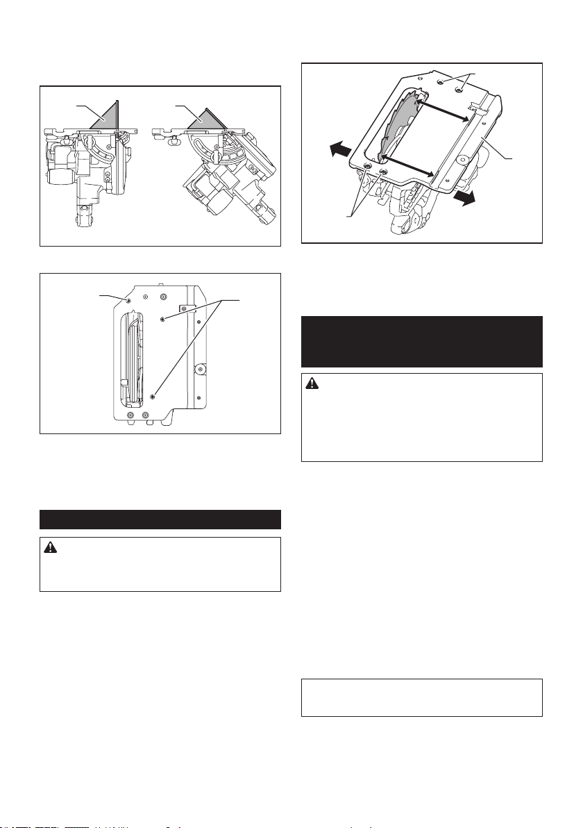
45 ESPAÑOL
2. Haga que la base quede perpendicular o a 45° al
disco de la sierra circular usando una regla triangular
girando el tornillo de ajuste con una llave hexagonal.
También puede usar una escuadra para ajustar el
ángulo a 0°.
1 1
► 1. Regla triangular
2
1
► 1. Tornillo de ajuste para ángulo a 0° 2. Tornillo de
ajuste para ángulo a 45°
3. Apriete los tornillos de jación, y luego haga un
corte de prueba para vericar que se haya obtenido el
ángulo deseado.
Ajuste del paralelismo
PRECAUCIÓN: Mantenga el paralelismo
exacto. De lo contrario, el disco de la sierra circular
puede morder el carril guía, el cual si está dañado
puede causar una lesión.
Este ajuste ha sido efectuado de fábrica. Pero en caso
de haberse perdido, usted puede ajustarlo siguiendo el
procedimiento a continuación.
1. Coloque la herramienta a la profundidad de corte
máxima.
2. Asegúrese de que todas las palancas y tornillos
estén apretados.
3. Aoje los tornillos mostrados en la ilustración.
4. Mientras abre el protector inferior, mueva la parte
trasera de la base de manera que las distancias A y B
sean iguales.
1
B
A
2
1
► 1. Tornillo 2. Base
5. Apriete los tornillos y haga un corte de prueba
para vericar el paralelismo.
ACCESORIOS
OPCIONALES
PRECAUCIÓN: Estos accesorios o aditamen-
tos están recomendados para utilizarse con su
herramienta Makita especicada en este manual.
El empleo de cualquier otro accesorio o aditamento
puede conllevar el riesgo de lesiones personales.
Utilice los accesorios o aditamentos solamente para
su n establecido.
Si necesita cualquier ayuda para más detalles en
relación con estos accesorios, pregunte a su centro de
servicio local Makita.
• Disco de la sierra circular
• Tope lateral de corte (regla de guía)
• Gancho
• Carril guía
• Guía de bisel
• Pinza
• Hoja
• Hoja de hule
• Hoja de posición
• Boquilla para polvo
• Llave Allen (hexagonal)
• Unidad inalámbrica
• Batería y cargador originales de Makita
NOTA: Algunos de los artículos en la lista pueden
incluirse en el paquete de la herramienta como acce-
sorios estándar. Éstos pueden variar de país a país.

46 ESPAÑOL
GARANTÍA LIMITADA DE
MAKITA
Ésta Garantía no aplica para México
Consulte la hoja de la garantía anexa para ver los
términos más vigentes de la garantía aplicable a este
producto. En caso de no disponer de esta hoja de
garantía anexa, consulte los detalles sobre la garantía
descritos en el sitio web de su país respectivo indicado
a continuación.
Estados Unidos de América: www.makitatools.com
Canadá: www.makita.ca
Otros países: www.makita.com

47

Some dust created by power sanding, sawing, grinding, drilling, and other
construction activities contains chemicals known to the State of California
to cause cancer, birth defects or other reproductive harm. Some examples
of these chemicals are:
• lead from lead-based paints,
• crystalline silica from bricks and cement and other masonry products, and
• arsenic and chromium from chemically-treated lumber.
Your risk from these exposures varies, depending on how often you do this
type of work. To reduce your exposure to these chemicals: work in a well
ventilated area, and work with approved safety equipment, such as those
dust masks that are specially designed to filter out microscopic particles.
WARNING
< USA only >
ADVERTENCIA
Algunos polvos creados por el lijado, aserrado, esmerilado, taladrado y
otras actividades de la construcción contienen sustancias químicas
reconocidas por el Estado de California como causantes de cáncer, defectos
de nacimiento y otros peligros de reproducción. Algunos ejemplos de estos
productos químicos son:
• plomo de pinturas a base de plomo,
• sílice cristalino de ladrillos y cemento y otros productos de albañilería, y
• arsénico y cromo de maderas tratadas químicamente.
El riesgo al que se expone varía, dependiendo de la frecuencia con la que
realice este tipo de trabajo. Para reducir la exposición a estos productos
químicos: trabaje en un área bien ventilada y póngase el equipo de seguridad
indicado, tal como las máscaras contra polvo que están especialmente
diseñadas para filtrar partículas microscópicas.
< Sólo en los Estados Unidos >
Makita Corporation
3-11-8, Sumiyoshi-cho,
Anjo, Aichi 446-8502 Japan
www.makita.com
885789-946
GSH02-1
EN, ESMX
20191217