Thank you very much for purchasing our air conditioner. Please read this owen's manual carefully before
using your air conditioner.
User Manual
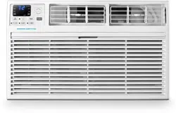
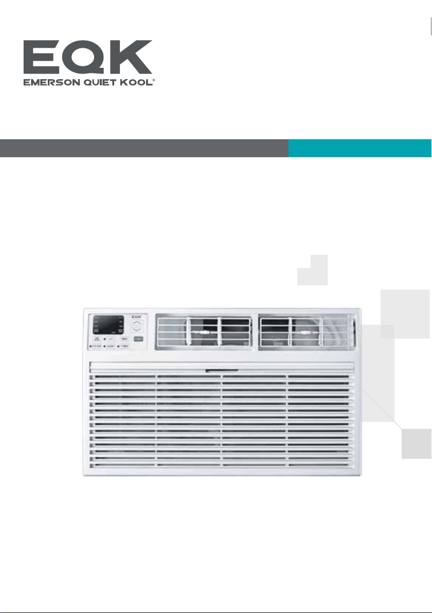
Thru-The-Wall Air Conditioner
Model No.: E*TC08RE1T E*TC08RSE1T E*TE08RE1T
E*TE08RSE1T E*TC10RE1T E*TC10RSE1T
E*TC10RE2T E*TC10RSE2T E*TE10RD2T
E*TE10RSD2T E*TC12RE1T E*TC12RSE1T
E*TC12RE2T E*TC12RSE2T
E*TE12RSD2T
E*TE12RD2T
E*TC14RD2T E*TC14RSD2T
E*TE14RD2T E*TE14RSD2T
Important Safety Instructions
Electrical Requirements
Packing List
Installation & Assembly Instructions
Using Your Air Conditioner
Operating Your Air Conditioner
Care And Cleaning
Troubleshooting
1
2
3
4
7
9
10
11
For any questions or Technical Support,
please contact us by mail info@geektechnology.com or by phone 1- 844 - 801 - 8880.
THANK YOU
Congratulations on your purchase and welcome to the Family.
Your new Dehumidifier combines high-efficiency operation with
portable convenience.
By following the operating and care instructions in this manual,your Dehumidifier will
provide you with many years of reliable service.
Please visit our website
www.emersonquietkool.com
Scan the QR code for more
assistance and support.

1
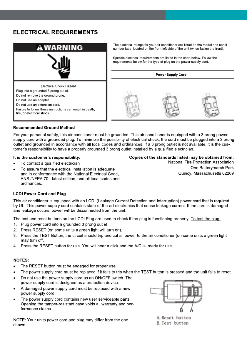
FCC Caution.
This device complies with part 15 of the FCC Rules. Operation is subject to the following two
conditions: (1) This device may not cause harmful interference, and (2) this device must accept
any interference received, including interference that may cause undesired operation.
Any Changes or modifications not expressly approved by the party responsible for compliance
could void the user's authority to operate the equipment.
2
8K/10K/12K-115V
Cooling
8K/10K/12K/14K
Cooling & Heating
10K/12K/14K-230V
Cooling
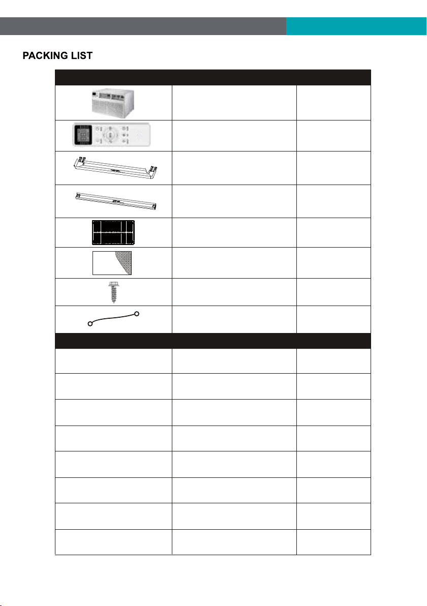
3
1/2" Long Hex-head Screw
Grouding wire with tooth washer
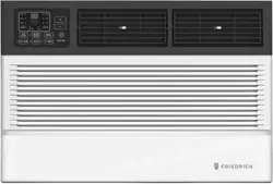
Through-The-Wall Air Conditioner
Remote Controll
Trim Frame 1 (Left&Right legs)
Trim Frame 2 (Top&Bottom legs)
Grille Aluminum
Rear plastic net
PAPT
QUANTITYIMAGE
PAPT QUANTITYDimension
Seal sponge1’’x3/4’’x14’’ 2
Seal sponge1’’x3/8’’x14’’ 2
Seal sponge1’’x3/8’’x25’’
3
Seal sponge1’’x11/2’’x25’ ’ 3
Seal sponge1’’x11/2’’x14’ ’ 2
Seal sponge1’’x11/2’’x84’ ’
1
Seal cotton3 3/4’’x11/2’’x4’’ 4
Seal cotton3/4’’x11/2’’x17’ ’ 2
4
1
1
1
2
2
1
1
4
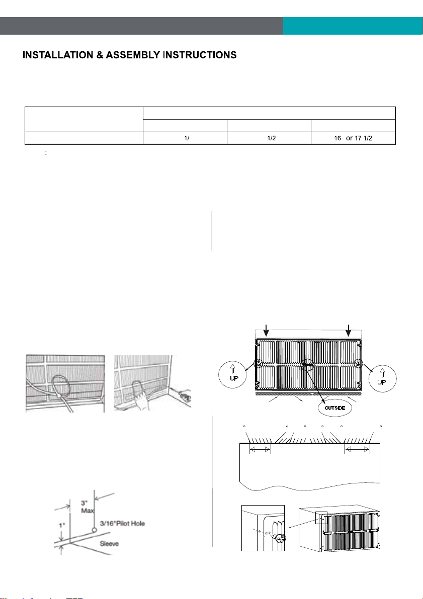
Condition1: Install the back grille to the Wall-sleeve (Prior Suggestion)
1, Identify the wall-sleeve brand for your preparing, from the below chart.
Type
Wall-sleeve Dimensions
Height Width
Depth
Standard Dimension
15 4’’
25 ’’
’’ ’’
NOTE
a, All wall sleeves used to mount the new air conditioner must be in sound structural condition and have a rear grille
that securely attached to the sleeve, or rear flange that serves as a stop for the air conditioner.
b, If you choose other wall-sleeve, be sure the dimension is suitable for the product.
c, The wall-sleeve you selected must be installed fasten to the wall with screw.
d, When do the performance testing, we suggest cancel the wall-sleeve, and install the new back grille with the new
unit, to avoid the wrong installation worse affect.
2, Prepare the Wall-sleeve before installation the unit.
(1) Remove old Air Conditioner from wall sleeve and pre-
pare as followings:
a, Clean interior (Re-stick the seals if necessary).
b, Check the wall sleeve be securely fastened in wall be-
fore installing. Add more nails or screws if needed.
c, Repair painted surface if needed.
(2) Remove the back grille.
Important: The old intake grille must be removed and re-
placed by the dual intake grille included with the TTW unit.
Warning: When removing the grille, protect from falling by
securing with a leash. Fasten by strapping looped through
the grille and secured with a knot. Holding the grille by the
leash with one hand the retaining screws can be removed
and the grille can be brought inside through the front of the
sleeve.
(3) Check the grounding wire hole.
a, If it does not exist, drill a 3/16'' pilot hole through the left
hand side of the sleeve, in a clear area about 3 inches max
deep from the front edge as below.
b, Fasten the grounding wire with screw to the drilled hole,
and pull the loose end of the ground wire out of the front of
the sleeve and bend it away from the opening. This will be
attached to the air conditioner once installed.
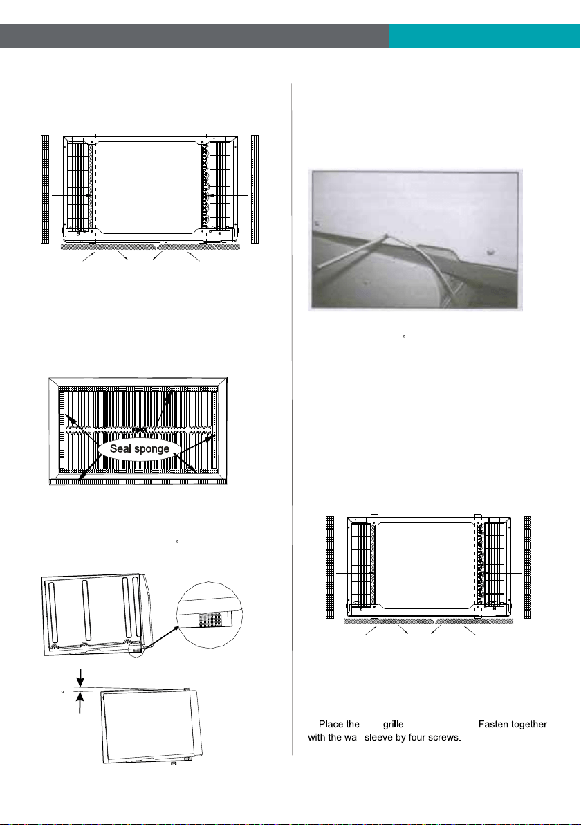
3, Replace the back grille.
a, Remove the old grille, and install with the dual intake
coming with the TTW unit. Take attention the remark on
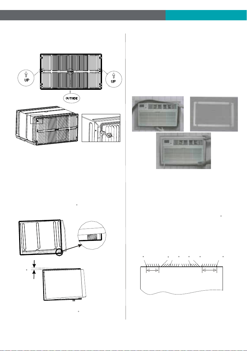
the new back grille (if it appears).
b, Put the [OUTSIDE] remark toward to the back side of
wall-sleeve, and let the arrow remark toward upside.
c, Be sure that, from the back side of the wall-sleeve,
the seven inlet opening should be at left, and the eight
inlet opening should be at right.
d, Place the grille included with your new air conditioner
towards the inside rear of the sleeve. Fasten together
with the wall-sleeve by four screws.
Left intake
Seven Opening
TOP VIEW from the unit
Right intake
Eight Opening
70
50
5070 70 70
Left intake
Seven Opening
Right intake
Eight Opening
New Dual Intake Grille
5
4, Install the Seal.
(1) Stick 1’’x4/5’’x13 4/5’’ sponges to the condenser side
plate, for both left and right at the back side of TTW unit.
(2) Seal the Wall-sleeve inside.
a, Seal the internal back side of wall-sleeve by sponges.
b, Seal and stick the top and bottom inside back edge by
two 1’’x1 1/2’’x25’’ long and thick sponges.
c, Seal and stick the left and right inside back edge by two
1’’x1 1/2’’x13 4/5’’ shorter and thick sponges.
IMPORTANT: Be sure that, these seal sponges will not bl-
ock the back grille inlet opening. If they effect the air-inlet
or outlet, cut them to the suitable dimension or thickness.
5, Set the tilt angle backward.
(1) Cut two suitable dimension of pearl seal cottons, and
stick to the front bottom of wall-sleeve.
(2) Be sure that, there will be a 3 tilt angle backward
of the sle eve a nd unit, when slide in the TTW unit.
6, Install the grounding wire.
a, Install screw end of ground wire into inside of sleeve
according to preparation instruction.
b, Remove the second screw from left side of unit, and
remove the screw plastic washer.
c, Screw the other end of the ground wire into the unit.
Make sure the toothed washer is against the cabinet.
Condition2: Install the back grille to the TTW
7, Gently slide the TTW unit into wall-sleeve. Be sure that,
the unit should be a 3 tilt angle backward.
If necessary , add some pearl cotton to the unit bottom.
In case where the dual intake grille cannot be mounted di-
rectly to the sleeve. It is desirable to attach the grille to the
back of the TTW unit to the hole pre-drilled in the unit.
1, Prepare the wall-sleeve followed the Condition 1 part.
2, Stick 1’’x4/5’’x13 4/5’’ sponges to the condenser side
plate, for both left and right at the back side of TTW unit.
3, Install the back grille to the back side of the TTW unit to
the hole pre-drilled. Take attention the remark on back grille
including in the new unit, if it appears.
a, Put the [OUTSIDE] remark toward to outside, and let the
arrow remark toward upside.
b, new to the TTW unit
Wall-Sleeve
Rear
Front
3
6
Left intake
Seven Opening
TOP VIEW from the unit
Right intake
Eight Opening
70
50
5070 70 70
5, Set the tilt angle backward followed the Condition 1 part.
(1) Cut two suitable dimension of pearl seal cottons, and
stick to the front bottom of wall-sleeve.
(2) Be sure that, there will be a 3 tilt angle backward
of the sleeve and unit, when slide in the TTW unit.
6, Gently slide the TTW unit into wall-sleeve. Be sure that,
the sleeve and unit should be a 3 tilt angle backward.
If necessary, add some pearl cotton to the unit bottom.
4, Seal the Wall-sleeve inside. Seal the internal back side
of wall-sleeve followed condition 1 part.
Important: Be sure that, all the seal sponges will not block
the back grille inlet opening. If they effect the air-inlet or
outlet, cut them to the suitable dimension or thickness.
c, Be sure that, from the back side of the TTW, the seven
inlet opening should be at left, and the eight inlet opening
should be at right.
Trim Kit Installation Instructions
1. Install the 1''x1 1/2'' x84'' long stuffer seal between the
wall sleeve and the unit. A flat-bladed screwdriver or putty
knife is needed.
2. Assemble the trim frame by inserting the top and bottom
pieces into side pieces and snapping into place.
3. Pull the cord through the trim frame and slide the trim
over the unit until flush with the wall.
Important: Be sure that, the gap between wall-sleeve and
unit, is well sealed by sponge all around. If necessary, add
some extra sponge and adhesive tap to fill it.
Energy saving suggestion: In order to reach the maxi-
mum energy saving and comfortable, it is necessary to
use an appropriately sized cover to provide additional
insulation and air sealing when the unit is not in use
during the off-using-season.
Testing Installation Instructions
1. When do the performance testing, we suggest cancel the
wall-sleeve, and install the new back grille to the new unit,
to avoid the wrong installation worse affect.
2. Install the back grille to the unit following Condition 2 part.
Use sponge and adhesive tap to fill all the gap around betw-
een the grille and TTW unit. Cut the sponge to suitable dim-
ension, be sure that, they will not effect the air-inlet or outlet.
3. Set the tilt angle, let the sleeve and unit be a 3 tilt angle
backward to outdoor side .
4. Set the indoor air-outlet louver at the center position, both
horizontal and vertical direction.
5. Add enough water to the outside chassis to let the heating
exchange of condenser be the best condition.
6. Check whether the back grille opening angle is well or not,
if necessary, repair or replace it.
Wall-Sleeve
Rear
Front
3
7
1
2
3
4 56 7 8 9
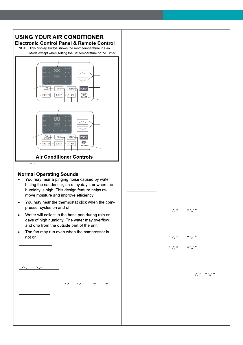
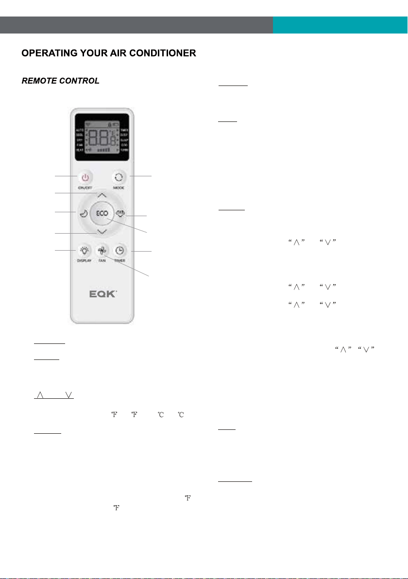
1. Without timer setting,the
operation mode is Cooling,Dry, Fan and Auto,and
the set temperature will be displayed.
Time will be displayed under timer setting.
Digital Display:
and Button:2. Use these buttons on the
control panel and remote to increase or decrease
the Set Temperature or Timer.
Temperature range: 61 ~88 or 16 ~31 .
3. Turn the air conditioner on and off.Power Button:
Press the mode button to cycle
through the various modes: Cool, Dry, Fan and
Auto, or Heat.
4. Mode Button:
Use these buttons on the control
panel and remote to set the Timer.
Timer Off: The timed stop is programmed by
pressing TIMER button. Set the rest time by
pressing the button or until the rest
time displayed is to your demand then press
TIMER button again.
Timer On: When the unit is off, press TIMER
button at the first time, set the temperature with
pressing the button or . Press TIMER
button at the second time, set the rest time with
pressing t
he button or . Press TIMER
button at the third time, confirm the setting, then
the rest time to next automatical switching-on
could be read on the display of the machine.
Note: It can be set to automatically turn off or on in
0.5-24 hours. Each press of the
buttons will increase or decrease the timer. The
Timer can be set in 0.5 hours increment below 10
hours and 1 hour increment for 10 hours or above.
The SET light will turn on while setting.
To cancel
the setted function, press the TIMER
button again.
5. Timer Button:
Cool Mode: The cooling function allows the air
conditioner to cool the room and at the same time
reduces Air humidify. Press the MODE button to
activate the cooling function. To optimize the
function of the air conditioner, adjust the
temperature and the speed by pressing the button
indicated.
Dry Mode: This function reduces the humidity of
the air to make the room more comfortable. Press
MODE button to set the DRY mode. An automatic
function of alternating coolin
g cycles and air fan
is activated.
Fan Mode: The conditioner works in only
ventilation. Press MODE button to set the FAN
mode. With pressing FAN SPEED button the
speed changes in the following sequence: Hi, Med
and Lo in FAN mode.
Auto Mode: In AUTO mode the unit automatically
chooses the fan speed and the mode of operation
(COOL,DRY or FAN).In this mode the temperature
is set automatically according to the room
temperature (tested by the temperature sensor
which is incorporate
d in the indoor unit.).
Heat Mode: The heating function allows the air
conditioner to heat the room. Press the MODE
button to activate the heating function. To optimize
the function of the air conditioner, adjust the
temperature and the speed by pressing the button
indicated.
AUTO
SPEED
AUTO
MODE
1
2
3
4 56 7 8 9
HEAT
AUTO
SPEED
AUTO
MODE
For Cooling model
For Heating model
WIFI
WIFI
WIFI Symbol*
Only available
for WIFI
models.
NOTE: * means only available for WIFI modes, For more
information, please see the WIFI manual.
Only available
for WIFI
models.
WIFI Symbol*
8
When the unit is in ECO mode, the
light will turn on. In ECO mode, the unit will
turn-off once the room is cooled to the user set
temperature.
The unit will turn back on when the room
temperature rises above the user set temperature.
Before the compressor stars, the fan motor will
run for a while, then it will stop for a while-and will
repeat to provide a much more comfortable-feeling
and save energy.
6. Eco Button:
Press the SLEEP button, all
of the display lights will turn off after a while, but
the Sleep light is always on. In SLEEP mode, the
air conditioner will automatically adjust the
temperature and fan speed to make the room
more comfortable during the night. The set
temperature will automatically raise every 30-60
minutes, and at most change sixtimes until the set
temperature is 81 or 82 .
7. Sleep Button:
Press the FAN SPEED button
to choose the fan speed options. You can choose
Hi, Med, Lo or auto speed in COOL mode and
choose Hi, Med, Lo in FAN mode.
8. Fan Speed Button:
9.
When the Filter Check light is off,
it is useless to press the Filter Check button. When
the Filter Check light is on, it can turn off the light
by pressing the Filter Check button. After the
fan motor works for 500 total hours, the Filter
Check light will turn on to remind the user to clean
the filter.
Filter Button:
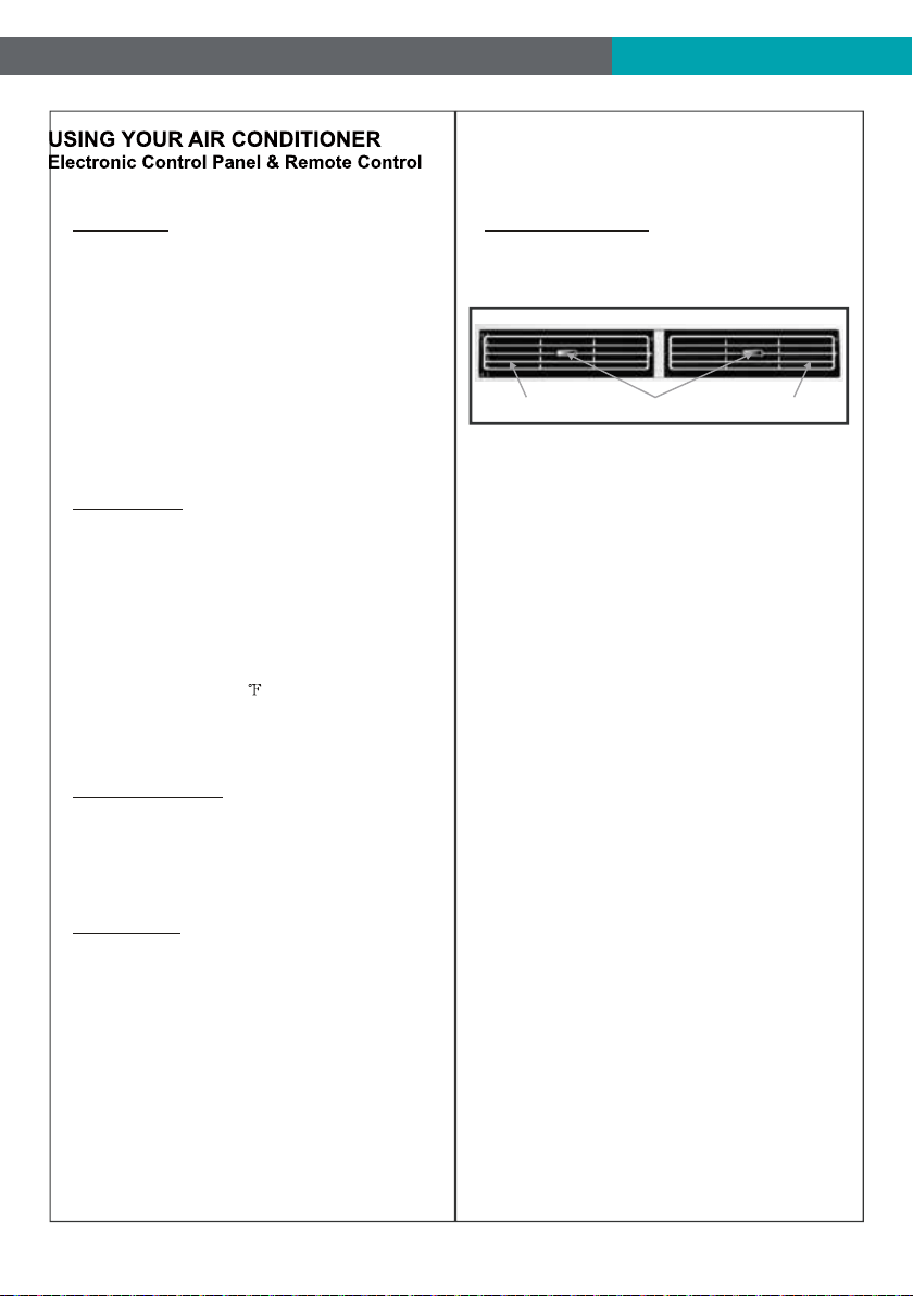
10.
To direct the airflow,
horizontal wheel to control the horizontal direction,
air deflector to control the vertical direction.
Directional Louvers:
horizontal wheelair deflector air deflector
9
1. Turn the air conditioner on and off.POWER:
2.
and :
3. Use these buttons to increase or
decrease the Set Temperature or Timer.
Temperature range: 61 ~88 or 16 ~31 .
Press the button to select the mode of
operation, AUTO, COOL, DRY, FAN, HEAT.
Note: The HEAT mode is only for some heating
models.
MODE:
SLEEP:4.
Press the SLEEP button, all of the dis-
play lights will turn off after a while, but the sleep
light is always on. In the mode, the airconditioner
will automatically adjust the temperature and fan
speed to make the room more comfortable during
the night. The set temperature will automatically
change every 30-60 minutes and at most change
six times until the set temperature is 81 or 82
for cooling and 75 or 76 for heating.
Battery Size:
AAA - NOTE: Do not mix old and new batteries or different types of AAA batteries..
Press the FAN SPEED button to choo
se
the fan speed options. You can choose Hi, Med,
Lo or auto speed in COOL or HEAT mode and
choose Hi, Med, Lo in FAN mode.
9.
FAN:
5.
6.
8.
TURBO:
When the remote is ON, press the
button to active the TURBO function, under
AUTO/COOL/FAN/HEAT mode.
When the unit is in ECO mode, the light
will turn on. In ECO mode, the unit will turn-off
once the room is cooled to the user set
temperature. The unit will turn back on when the
room temperature rises above the user set
temperature. Before the compressor stars, the
fan motor will keep running for a while and stop
for a while-and again, to provide much more
comfortable feeling, and save
the energy.
ECO:
Use these buttons on the control panel
and remote to set the Timer.
Timer Off: The timed stop is programmed by
pressing TIMER button. Set the rest time by
pressing the button or until the rest
time displayed is to your demand then press
TIMER button again.
Timer On: When the unit is off, press TIMER
button at the first time, set the temperature with
pressing the button or . Press TIMER
button at the second time, set the rest time with
pressing the button or
. Press TIMER
button at the third time, confirm the setting, then
the rest time to next automatically switching-on
could be read on the display of the machine.
Note: It can be set to automatically turn off or on
in 0.5-24 hours. Each press of the
buttons will increase or decrease the timer. The
Timer can be set in 0.5 hours increment below
10 hours and 1 hour increment for 10 hours or
above. The SET light will turn on while setting.
To cancel the setted function, press t
he TIMER
button again.
7. TIMER:
To press the DISPLAY button, it can
switch off/on all lights or LED display.
DISPLAY:
2
6
5
8
7
1
3
4
9
3
10
FIG.21
FIG.21
11
12


Emerson Quiet Kool Co. Ltd.
1275 Bloomfield Ave 16-141
Fairfield NJ 07004 USA
Toll Free 1-844-801-8880
Version Update:--2021.5.0