
3531835447
_BLE OF (IION]_ENT$
Safety Information ...................... 2
Important Installation Instructions ...... 2
Safety Features ......................... 2
Pre-installation Checklist ................ 3
Garage Door Opener Assembly ......... 9
Record Data (for Service) .............. 11
Garage Door Opener Installation ....... 12
Accessories ........................... 22
Maintenance .......................... 25
Troubleshooting ...................... 26
Wiring Diagram ....................... 29
Warranty information .................. 30
wm-I IB_]:ELLIC I .....' .... ,.Os_E
BI_:0o0o0,.o1_:t0BOLy..,.o°0.s,SEI/_:::_
For 7' 6" Doors, Extension Kit is available for 8' Doors
included Wall Control MUST be installed prior to Operation
of this Garage Door Operator,
Safe-T-Beam ® Safety Reverse System Must be installed and
the Force Controls MUST be Properly Set to close door.
This Equipment meets or exceeds all Federal, State and UL325
Safety Requirements.
Will not operate twice as fast on a one-piece door,
Please call us: 1-800-35-GENiE (354-3643)
www.geniecompany, com
Please have Model information ready when calling.

GarageDoorsareheavyobjectsthatmovewiththehelpofsprings
underhightensionandelectricopeningequipment.Sincemoving
objects,springsundertension,andelectricopeningequipment
maycauseinjuries,yoursafetyandthesafetyofothersdependon
youreadingandunderstandingtheinformationinthismanual.
Ifyouhavegaragedoorrelatedquestionsordonotunderstandthe
informationpresented,callyournearestGenieFactoryAuthorized
Dealerlistedatwww.geniecompany.com,orcustomerServiceat
1-800-35-GENIE..
MOVINGDOOR
ELECTRICALSHOCK
HIGHSPRINGTENSION
WARNING:
Can Cause Serious
Injury or Death
WARNING:
Can Cause Serious
Injury or Death
WARNING:
Can Cause Serious
Injury or Death
o Keep people clear of opening while door is moving.
o Do Not allow children to play with the door operator.
o Do Not operate a door thatjams or one that has a broken spring.
oTurn off power before removing operator cover.
oWhen replacing cover, make sure wires are not pinched or near
moving parts.
oOperator must be properly grounded.
oDo Not try to remove, repair or adjust springs or anythinqto
which door sprinq parts are tastened, such as, woodl blocks,
steel brackets, cables or other like items.
oRepairs and adjustments must be made by a trained service
person using proper tools and instructions.
.& WARNING;
TO REDUCE THE RISK OF SEVERE INJURY OR DEATH:
1 READAND FOLLOW ALL SAFETY,INSTALLATIONAND
OPERATIONINSTRUCTIONS.If you have any
questions or do not understand an instruction, call
your service representative.
2 Do Not install operator on an improperly balanced
door. An improperly balanced door could cause
severe injury. Repairs and adjustments to cables,
spring assembly, and other hardware must be made
by a trained service person using proper tools and
instructions.
3 Remove all ropes, and disable all locks connected to
the door before installing operator.
4 Install door operator 7 feet or more above the floor.
Mount the emergency release knob 6 feet above
the floor.
5 Do Not connect the operator to the source of power
until instructed to do so.
6 Locatethe control button:
• Within sight of door.
• At a minimum height of 5 feet, so small children
cannot reach it.
• Away from all moving parts of the door.
7 Install the entrapment WARNING label next to the
wall button or console. Install the emergency release
tag on, or next to, the emergency release
8 The operator must reverse when the door contacts a
1-1/2 inch high object on the floor at the center of
the doorway.This is about the size ofa 2"x 4" board
laid flat.
Safe-T-Beam ® (STB) Non-Contact Reversing System
Places an invisible beam across door opening, that reverses
the door during down travel to the fully open position if
anything passes through beam.
Safe-T-Reverse ® Contact Reversing System
Automatically stops and reverses a closing door within 2
seconds of contact with an object.
Safe-T-Stop ® Timed Reversed System
Automatically opens a closing door, if door does not close
within 30 seconds.
Force Guard ® Control
Used to set the force required for opening and closing
door. For maximum safety, set the minimum force required
to fully open and close door.
Automatic Lighting System
Two light bulbs up to 60 Watts max. each, are used for safer
entries and exits.The light turns on when door is activated
and automatically turns off 4.5 minutes later.
Manual Emergency Release
Allows the garage door to be opened or closed manually
for emergencies or maintenance.
This Opener includes parts and supplies needed to install in most garages and
connect to most garage doors. There are many variations of garages and garage
doors. A few additional parts and supplies may be needed to install Opener into
your garage and connect to your garage door. While checking items listed
below, note any additional items you will need.
TOol ued _ t_i ectio_s
• 12'+ Tape Measure . Pencil . Ladder . Level
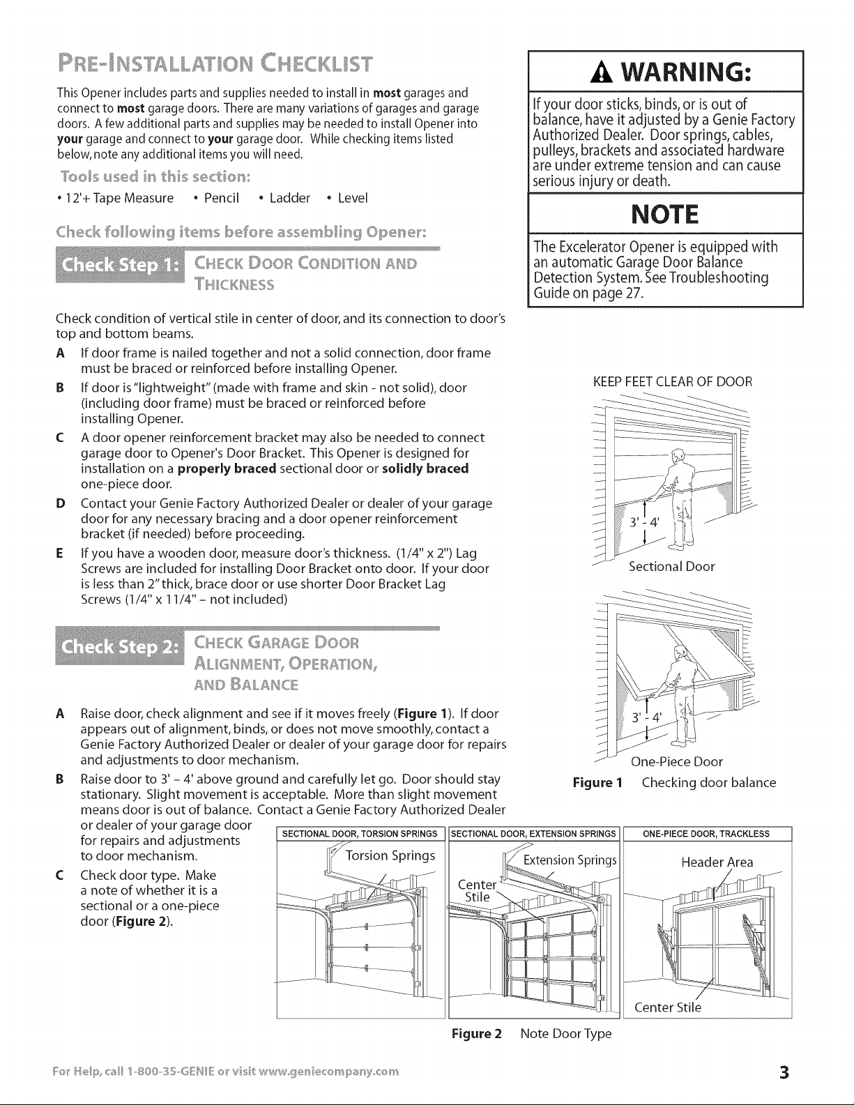
Check condition of vertical stile in center of door, and its connection to door's
top and bottom beams.
A If door frame is nailed together and not a solid connection, door frame
must be braced or reinforced before installing Opener.
B If door is"lightweight" (made with frame and skin - not solid), door
(including door frame) must be braced or reinforced before
installing Opener.
C A door opener reinforcement bracket may also be needed to connect
garage door to Opener's Door Bracket. This Opener is designed for
installation on a properly braced sectional door or solidly braced
one-piece door.
D Contact your Genie Factory Authorized Dealer or dealer of your garage
door for any necessary bracing and a door opener reinforcement
bracket (if needed) before proceeding.
E If you have a wooden door, measure door's thickness. (1/4" x 2") Lag
Screws are included for installing Door Bracket onto door. If your door
is less than 2"thick, brace door or use shorter Door Bracket Lag
Screws (1/4" x 11/4"- not included)
WARNING:
If your door sticks,binds,or is out of
balance,have it adjusted by a Genie Factory
Authorized Dealer. Door springs,cables,
pulleys,bracketsand associatedhardware
are under extreme tension and can cause
seriousinjury or death.
NOTE
The Excelerator Opener is equipped with
an automatic Garage Door Balance
Detection System. SeeTroubleshooting
Guide on page 27.
KEEP FEET CLEAR OF DOOR
Sectional Door
A
C
CHCK G£_£6 ©oo_
ALIGH _EIU I")OPEB£T 01%
Raise door, check alignment and see if it moves freely (Figure 1). If door
appears out of alignment, binds, or does not move smoothly, contact a
Genie Factory Authorized Dealer or dealer of your garage door for repairs
and adjustments to door mechanism.
Raise door to 3' - 4' above ground and carefully let go. Door should stay
stationary. Slight movement is acceptable. More than slight movement
means door is out of balance. Contact a Genie Factory Authorized Dealer
or dealer of your garage door
for repairs and adjustments SECTIONAL ._cj_DOOR'TORSION SPRINGS SECTIONAL DOOR, EXTENSION SPRINGS
to door mechanism. I_ Torsion Springs
Check door type. Make _/_-_411-_. "J
a note of whether it is a __ __-__, _
sectional or a one-piece __- _:_' -
door (Figure 2). _........ e ............
.............::]--+........
One-Piece Door
Figure 1 Checking door balance
ONE-PIECE DOOR, TRACKLESS
Header Area
_ Center Stile
Figure 2 Note Door Type
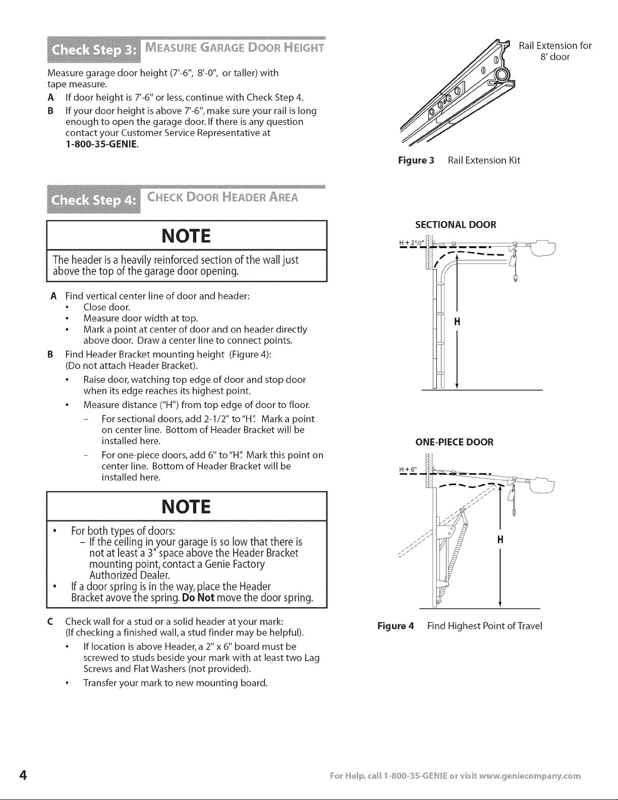
Measure garage door height (7'-6", 8'-0", or taller) with
tape measure.
A If door height is 7'-6" or less,continue with Check Step 4.
B If your door height is above 7'-6%make sure your rail is long
enough to open the garage door. If there is any question
contact your Customer Service Representative at
1-800-3S-GENIE.
Figure 3 Rail Extension Kit
Rail Extension for
8' door
CH CKDOOR t_ AD R
NOTE
The header is a heavily reinforced section of the wall just
above the top of the garage door opening.
A
B
Find vertical center line of door and header:
• Close door.
• Measure door width at top.
• Mark a point at center of door and on header directly
above door. Draw a center line to connect points.
Find Header Bracket mounting height (Figure 4):
(Do not attach Header Bracket).
• Raise door, watching top edge of door and stop door
when its edge reaches its highest point.
• Measure distance ('H") from top edge of door to floor.
- For sectional doors, add 2-1/2" to"H': Mark a point
on center line. Bottom of Header Bracket will be
installed here.
- For one-piece doors, add 6" to"H': Mark this point on
center line. Bottom of Header Bracket will be
installed here.
C
NOTE
e
For both types of doors:
i
If the ceiling in your garage is so low that there is
not at least a 3" space above the Header Bracket
mountingpoint, contact a Genie Factory
AuthorizedDealer.
If a door spring is in the way, place the Header
Bracket avove the spring. Do Not move the door spring.
Check wall for a stud or a solid header at your mark:
(if checking a finished wall, a stud finder may be helpful).
• If location is above Header, a 2" x 6" board must be
screwed to studs beside your mark with at least two Lag
Screws and Flat Washers (not provided).
• Transfer your mark to new mounting board.
SECTIONAL DOOR
ONE-PIECE DOOR
H+6"
H
Figure 4 Find Highest Point of Travel
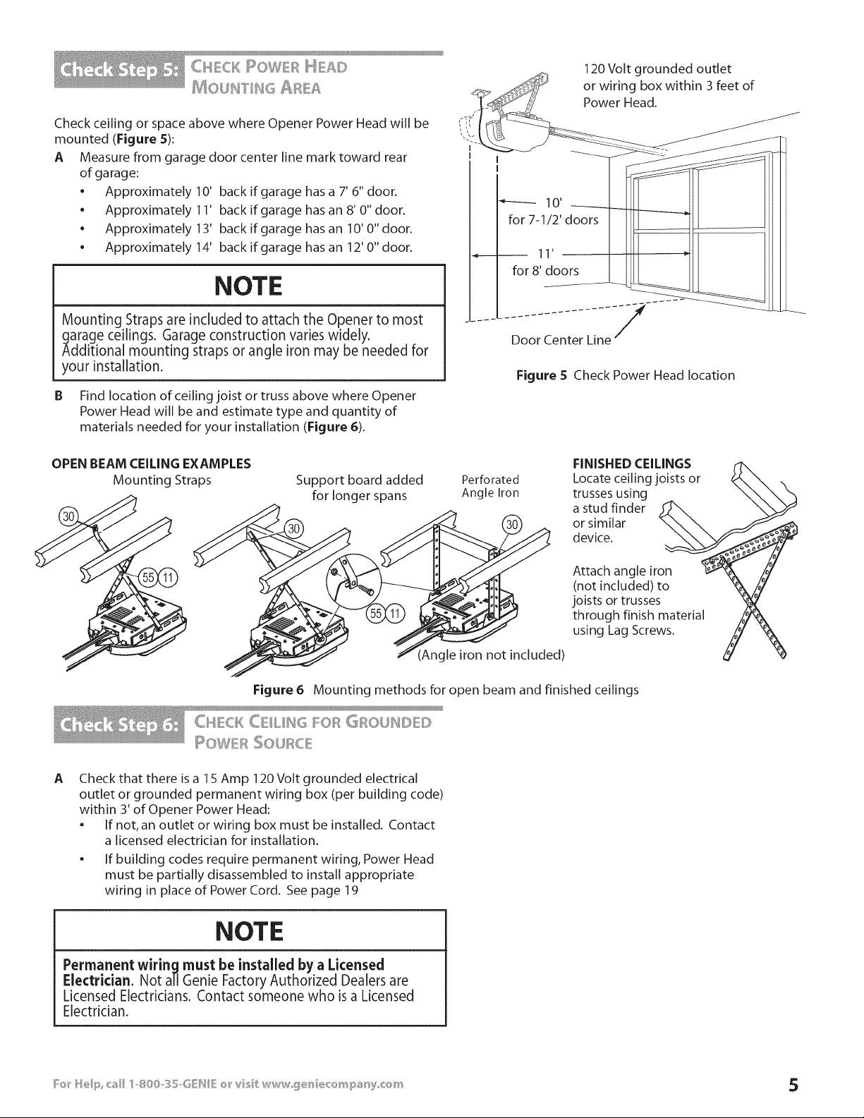
Check ceiling or space above where Opener Power Head will be
mounted (Figure S):
A Measure from garage door center line mark toward rear
of garage:
• Approximately 10' back if garage has a 7' 6" door.
• Approximately 11' back if garage has an 8' 0" door.
• Approximately 13' back if garage hasan 10'0"door.
• Approximately 14' back if garage hasan 12'0"door.
NOTE
Mounting Straps are included to attach the Opener to most
garage ceilings. Garage construction varies widely.
Additional mounting straps or angle iron may be needed for
your installation.
B Find location of ceiling joist or truss above where Opener
Power Head will be and estimate type and quantity of
materials needed for your installation (Figure 6).
120 Volt grounded outlet
4_ or wiring box within 3 feet of
°"f_ Power Head.
I IIIi "1 II
- - Door Center Line--
Figure S Check Power Head location
OPEN BEAM CEILING EXAMPLES
Mounting Straps
Support board added
for longer spans
Perforated
Angle Iron
FINISHED CEILINGS
Locate ceiling joists or
trusses using
a stud finder
or similar
device.
(Angle iron not included)
Attach angle iron
(not included) to
joists or trusses
through finish material
using Lag Screws.
Figure 6 Mounting methods for open beam and finished ceilings
CtICK C iI.iI_16 l::_,._Fl'_"6FlOUl_I[l [)
I OWER _:'_: '=°'°
,:;:_0JR_. £
A
Check that there is a 1S Amp 120 Volt grounded electrical
outlet or grounded permanent wiring box (per building code)
within 3' of Opener Power Head:
• If not, an outlet or wiring box must be installed. Contact
a licensed electrician for installation.
• If building codes require permanent wiring, Power Head
must be partially disassembled to install appropriate
wiring in place of Power Cord. See page 19
NOTE
Permanent wiring must be installed by a Licensed
Electrician. Not all Genie Factory Authorized Dealers are
Licensed Electricians. Contact someone who is a Licensed
Electrician.
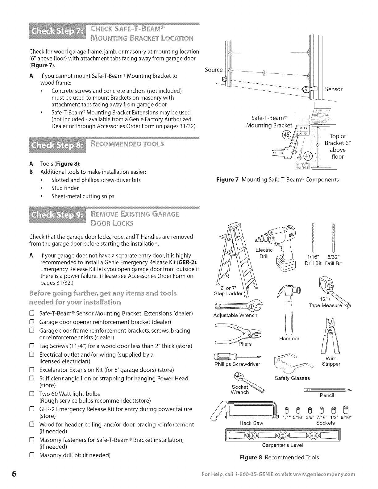
MOUF_ FIF_G _}RACiKE I" LOC£T OIU
Check for wood garage frame, jamb, or masonry at mounting location
(6" above floor) with attachment tabs facing away from garage door
(Figure 7).
A
If you cannot mount Safe-T-Beam ® Mounting Bracket to
wood frame:
• Concrete screws and concrete anchors (not included)
must be used to mount Brackets on masonry with
attachment tabs facing away from garage door.
• Safe-T-Beam ® Mounting Bracket Extensions may be used
(not included - available from a Genie Factory Authorized
Dealer or through Accessories Order Form on pages 31/32).
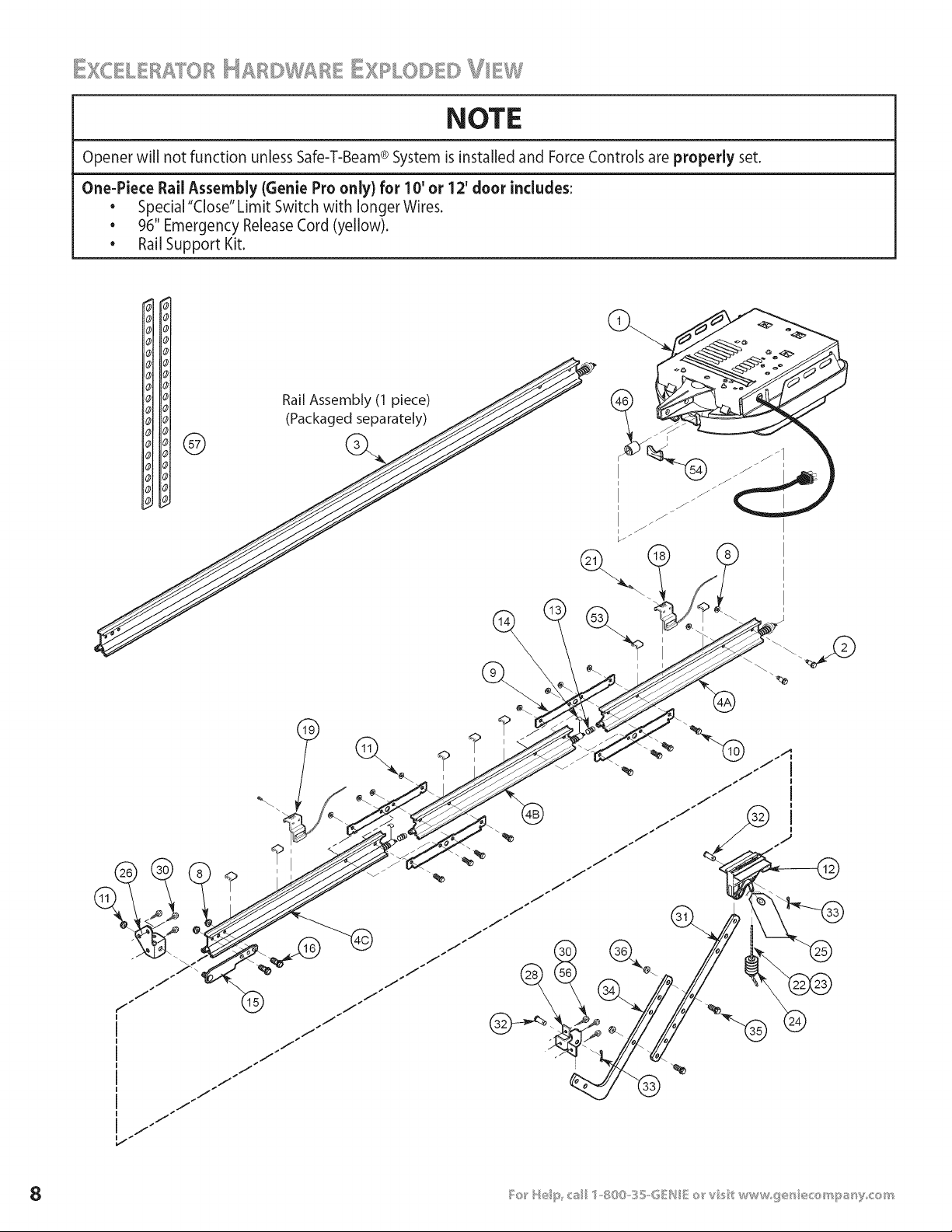
_ COBRSREIU[3E[)TOOLS
A
B
Tools (Figure 8):
Additional tools to make installation easier:
* Slotted and phillips screw-driver bits
. Stud finder
. Sheet-metal cutting snips
Figure 7
_3 Sensor
Safe-T-Beam ® i,_,
Mounting Bracket •__
Top of ,,
i , H 6" Bracket6
/4 _ I above
8 floor
Mounting Safe-T-Beam ® Components
i_ 140V" =......... ¢: . . ." E l!×l:JYlt< ,,:_GAFbS, QE
L;,RLOClS
Check that the garage door locks, rope, and T-Handles are removed
from the garage door before starting the installation.
A If your garage does not have a separate entry door, it is highly
recommended to install a Genie Emergency Release Kit (6ER-2).
Emergency Release Kit lets you open garage door from outside if
there is a power failure. (Please see Accessories Order Form on
pages 31/32.)
[] Safe-T-Beam ® Sensor Mounting Bracket Extensions (dealer)
[] Garage door opener reinforcement bracket (dealer)
[] Garage door frame reinforcement brackets, screws, bracing
or reinforcement kits (dealer)
[] Lag Screws (11/4") for a wood door less than 2" thick (store)
[] Electrical outlet and/or wiring (supplied by a
licensed electrician)
[] Excelerator Extension Kit (for 8' garage doors) (store)
[] Sufficient angle iron or strapping for hanging Power Head
(store)
[] Two 60 Watt light bulbs
(Rough service bulbs recommended)(store)
[] GER-2 Emergency Release Kit for entry during power failure
(store)
[] Wood for header, ceiling, and/or door bracing reinforcement
(if needed)
[] Masonry fasteners for Safe-T-Beam ® Bracket installation,
(if needed)
[] Masonry drill bit (if needed)
Drill 1_
6' or 7'
Step Ladder
Adjustable Wrench
Phillips Screwdriver
Hack Saw
1/16" 5/32"
Drill Bit Drill Bit
12' +
Tape
Hammer
Wire
Stripper
.......I
Safety Glasses
Pencil
888888
1/4" 5/16" 3/8" 7/16" 1/2" 9/16"
Sockets
Carpenter's Level
Figure 8 Recommended TooLs

L st
item Part Name Quantity
Required
1-Pc Rail 13-Pc Rail
1 Power Head Assembly (main carton) 1 1
2 1/4"-20 x 13/16" HexHead Shoulder Bolt (blue bag) 2 2
(yellow bolt)
3 Rail Assembly (1 piece#packaged separately) 1
4 Rail Assembly (3 piece)(main carton) 1
4A First RailSection 1
4B Middle RailSection 1
4C End Rail Section 1
8 1/4"-20 Hex Serrated Flange Nut (blue bag) 4 4
9 Rail Clamps (blue bag) 4
10 5/16"-18 x 11/16" Hex HeadShoulder Bolt (blue bag) 8
11 5/16"-18 Hex Serrated Flange Nut (blue & orange bags) varieS/modeI 12
12 Magnetic CarriageAssembly (main carton) 1 1
13 Collar (blue bag) 3
14 Retaining Clip (blue bag) 3
15 RailStrap (blue bag) 1 1
16 1/4"-20 Hex HeadBolt (blue bag) 2 2
18 Open Limit Switch Assembly (White)(green bag) 1 1
19 CloseLimit Switch Assembly (Brown) (green bag) 1 1
21 No.8-32 x 1" HexHead Screw (green bag) 2 2
22 Emergency ReleaseCord (green bag) 1 1
23 Emergency ReleaseCord (Iong)(yellow) 10'&12'only
24 Emergency ReleaseKnob (green bag) 1 1
25 Emergency ReleaseTag(green bag) 1 1
26 Header Bracket (orange bag) 1 1
28 Door Bracket (orange bag) 1 1
30 1/4" x 2" Lag Screw(orange bag) varieS/modeI 8
31 Straight Door Arm (main carton) 1 1
32 ClevisPin,3/8" x 15/16" (yellow bag) 2 2
33 Cotter Pin,.073" dia.(yellow bag) 2 2
34 Curved Door Arm (main carton) 1 1
35 3/8" x 7/8" Hex Head Bolt (yellow bag) 2 2
36 3/8" HexSerrated Flange Nut (yellow bag) 2 2
37_ 2-ConductorWire (main carton) 1 Roll 1 Roll
38_ Insulated Staple (red bag) approx.30 approx.30
40* Wall Console (main carton) 1 1
41" #6 x 1-1/4" Pan HeadScrew (red bag) 2 2
42* Entrapment Warning Label (manual)(main carton) 1 1
43* Safe-T-Beam(STB)Sensor (GreenLED)(maincarton) 1 1
44* Safe-T-Beam(STB)Source (Red LED#main carton) 1 1
45* Safe-T-Beam(STB)Bracket (yellow bag) 2 2
46 Coupler (blue bag) 1 1
47_ No.lO x l 1/4" Phillips HexHead Screw(yellow bag) 4 4
48_ 1 Button Remote Control (main carton) varieS/modeI varieS/modeI
49* 3 Button Remote Control (main carton) varieS/modeI varieS/modeI
SO* Wireless Keypad(main carton) varieS/modeI varieS/modeI
51" 2 Button Remote Control (main carton) varieS/modeI varieS/modeI
52* Safety & Maintenance Guide (manual)(main carton) 1 1
53 Wire Clip (green bag) 7
54 Bumper (blue bag) 1 1
SS* 5/16"-18x 3/4" HexHeadBolt(orange bag) 3
56 1/4-20 x 3/4" Self-drilling Screw(orange bag) 3 3
57 Mounting Straps(main carton) 2 2
Denotesitems not shown on page8. Theseitemswill be illustrated
throughout the manualasrequired.
Model Number
I_ f}' Serial Number
ROWER HEAD c ....,, B Ts L/ST
Item
1A
1B
lC
1D
1E
1G
1H
1K
1L
1M
1P
Part Name
Lens
Top Plate Assembly
Light Socket (2)
Motor Assembly
Cover
Motor Drive Board
Controller Board
No. 10-24 x 3/8" Hex Head
No.8-32 x 1" Phillips Screw
No. 8-32 x 3/8" Slotted Hex Head Screw
Power Cord
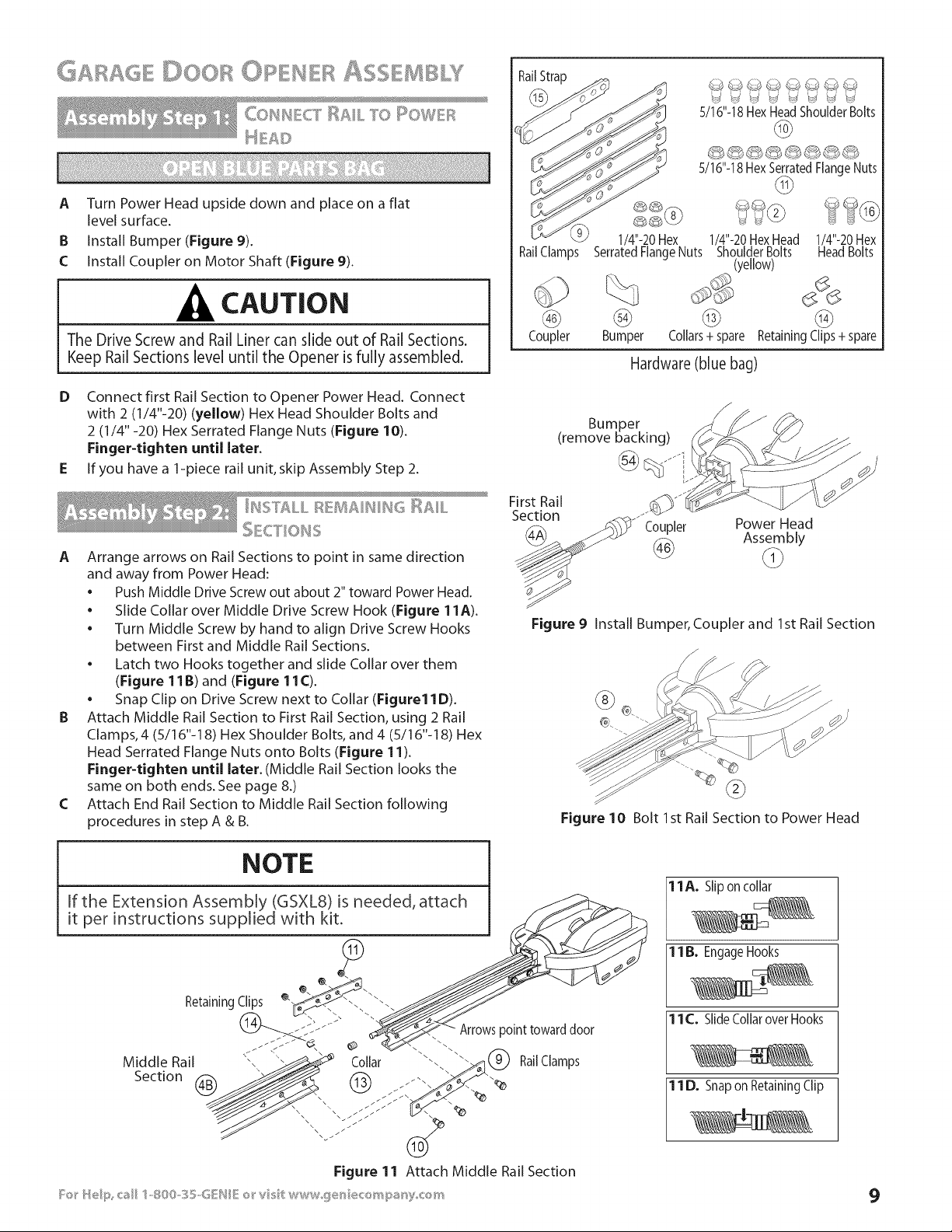
NOTE
Opener will not function unless Safe-T-Beam® System is installed and ForceControls are properly set.
One-Piece Rail Assembly {Genie Pro only) for 10' or 12' door includes:
• Special "Close" Limit Switch with longer Wires.
• 96" Emergency Release Cord (yellow).
• Rail Support Kit.
Rail Assembly (1 piece)
H Hol (Packaged separately) /_/ \ _
\
i
®
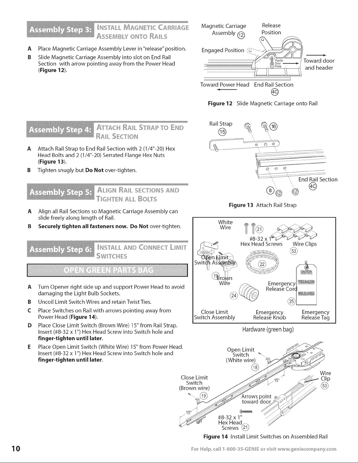
COIl CT RAIL TO I ©WEF_
A
B
C
Turn Power Head upside down and place on a flat
level surface.
Install Bumper (Figure 9).
Install Coupler on Motor Shaft (Figure 9).
CAUTION
The Drive Screw and Rail Liner can slide out of Rail Sections.
Keep Rail Sections level until the Opener is fully assembled.
D Connect first Rail Section to Opener Power Head. Connect
with 2 (1/4"-20) (yellow) Hex Head Shoulder Bolts and
2 (1/4"-20) Hex Serrated Flange Nuts (Figure 10).
Finger-tighten until later.
E If you have a 1-piece rail unit, skip Assembly Step 2.
A Arrange arrows on Rail Sections to point in same direction
and away from Power Head:
• Push Middle Drive Screw out about 2" toward Power Head,
• Slide Collar over Middle Drive Screw Hook (Figure 11A).
• Turn Middle Screw by hand to align Drive Screw Hooks
between First and Middle Rail Sections.
• Latch two Hooks together and slide Collar over them
(Figure 11B) and (Figure 11C).
• Snap Clip on Drive Screw next to Collar (Figure11D).
B Attach Middle Rail Section to First Rail Section, using 2 Rail
Clamps, 4 (5/16"-18) Hex Shoulder Bolts, and 4 (5/16"-18) Hex
Head Serrated Flange Nuts onto Bolts (Figure 11).
Finger-tighten until later. (Middle Rail Section looks the
same on both ends. See page 8.)
C Attach End Rail Section to Middle Rail Section following
procedures in step A & B.
RailStrap
RailClamps
@
Coupler
1/4"-20 Hex
SerratedFlangeNuts
%
@
Bumper
S/16"-18HexHeadShoulderBolts
@
5/16"-18HexSerratedFlangeNuts
@
1/4"-20HexHead 1/4"-20Hex
ShoulderBolts HeadBolts
(yellow)
@ @
Collars+ spare Retaining Clips + spare
Hardware (blue bag)
Bumper
(remove backing)
@ Jfi
First Rail
Section
Coupler Power Head
Assembly
Figure 9 Install Bumper, Coupler and 1st Rail Section
Figure 10 Bolt 1st Rail Section to Power Head
11A. Slipon collar
1B. EngageHooks
11 C._Slide Collar over Hooks
11 D._Snap on Retaining Clip
9
A
B
Place Magnetic Carriage Assembly Lever in "release" position.
Slide Magnetic Carriage Assembly into slot on End Rail
Section with arrow pointing away from the Power Head
(Figure 12).
Magnetic Carriage Release
Assembly _ Position
kCC/
Engaged Position (i_ .... -__/_/
To.o=
.................................. _ andheader
Toward Power Head End Rail Section
Figure 12 Slide Magnetic Carriage onto Rail
A]_]'ACH RAIL STRAR TO DU©
RAIL :_E_._[l,N
A Attach Rail Strap to End Rail Section with 2 (1/4"-20) Hex
Head Bolts and 2 (1/4"-20) Serrated Flange Hex Nuts
(Figure 13).
B Tighten snugly but Do Not over-tighten.
Rail Strap _@
'I? I & I "
ALIGH I_AIL SECTIONS ;_N©
A Align all Rail Sections so Magnetic Carriage Assembly can
slide freely along length of Rail.
B Securely tighten all fasteners now, Do Not over-tighten.
I¢2 = =_'_ & I "=S,>%, LL _S[} CONNECT LIIIIT
A
B
C
D
Turn Opener right side up and support Power Head to avoid
damaging the Light Bulb Sockets.
Uncoil Limit Switch Wires and retain Twist Ties.
Place Switches on Rail with arrows pointing away from
Power Head (Figure 14).
Place Close Limit Switch (Brown Wire) 15" from Rail Strap.
Insert (#8-32 x 1") Hex Head Screw into Switch hole and
finger-tighten until later.
Place Open Limit Switch (White Wire) 15" from Power Head.
Insert (#8-32 x 1") Hex Head Screw into Switch hole and
finger-tighten until later.
Figure 13 Attach Rail Strap
White
Wire
#8-32 x
Hex Head Screws
Wire Clips
Close Limit Emergency Emergency
Switch Assembly Release Knob Release Tag
Hardware (green bag)
Close Limit
Switch
(Brown wire)
%.
i
15"
Open Limit
Switch _--.
(White wire)
@
Wire
_15" j_- Clip
,rro..t
toward I_o_#i_
#8-32 x 1" --_"_
Hex Head_
Screws
Figure 14 Install Limit Switches on Assembled Rail
NOTE
o Loosen (Do Not Remove) Terminal Block Screws_
o Limit Switch adjustments and securing the Wires
will be done later.
F Lay Wires in channel on top of Rail and secure with Wire Clips
(Figure 14).
G Coil and bundle excess Limit Switch Wires on top of Power
Head with Twist Ties. Leave just enough Wire to reach
Terminals on back of Power Head (Figure 14).
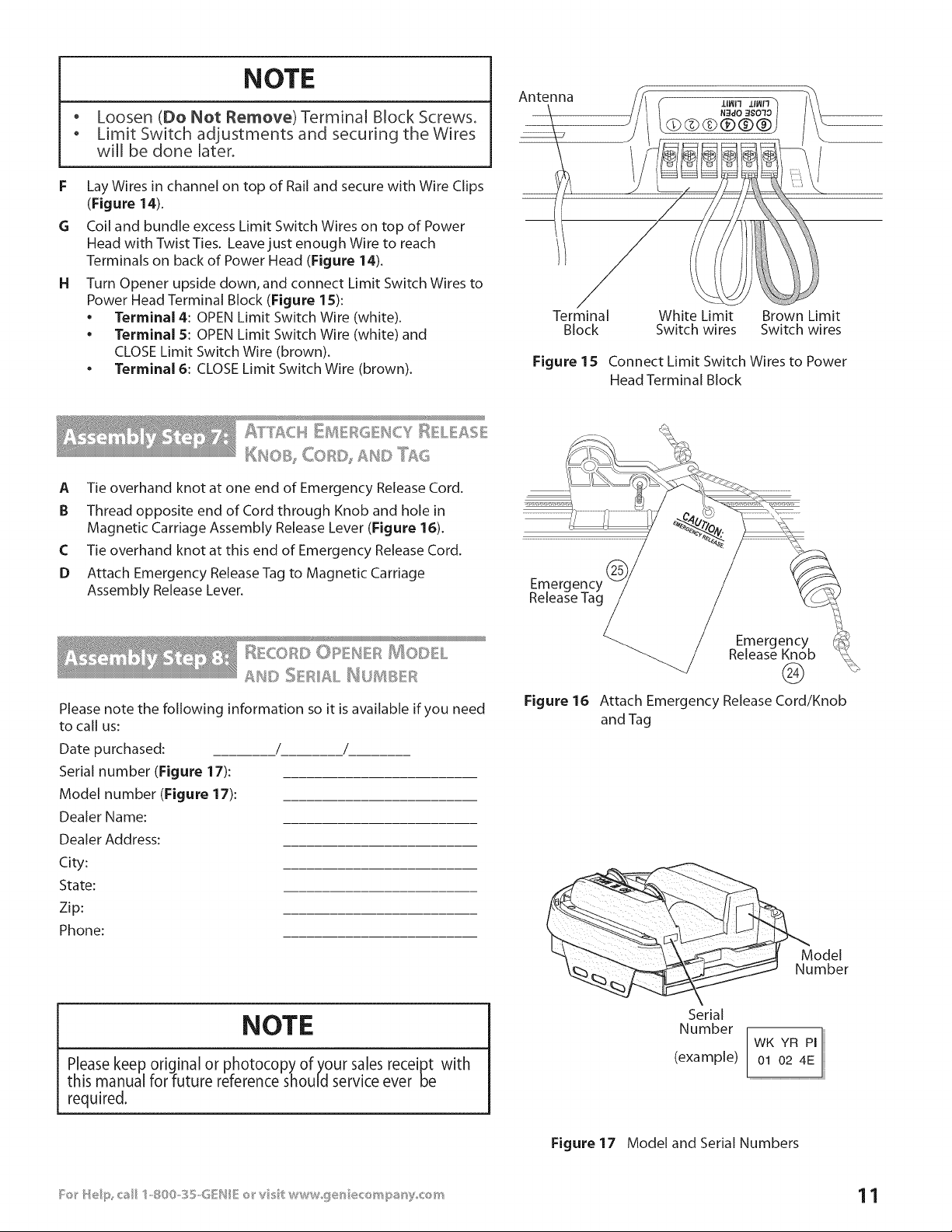
H Turn Opener upside down, and connect Limit Switch Wires to
Power Head Terminal Block (Figure lS):
• Terminal 4: OPEN Limit Switch Wire (white).
• Terminal 5: OPEN Limit Switch Wire (white) and
CLOSE Limit Switch Wire (brown).
• Terminal 6: CLOSE Limit Switch Wire (brown).
Antenna
Terminal White Limit Brown Limit
Block Switch wires Switch wires
Figure 15 Connect Limit Switch Wires to Power
Head Terminal Block
_ffT'£Ck¢ _D4 F_G _SCY_ L AS
A Tie overhand knot at one end of Emergency Release Cord.
B Thread opposite end of Cord through Knob and hole in
Magnetic Carriage Assembly Release Lever (Figure 16).
C Tie overhand knot at this end of Emergency Release Cord.
D Attach Emergency Release Tag to Magnetic Carriage
Assembly Release Lever.
Please note the following information so it is available if you need
to call us:
Date purchased: / /
Serial number (Figure 17):
Model number (Figure 17):
Dealer Name:
Dealer Address:
City:
State:
Zip:
Phone:
Figure 16
Emergency
Release Knob
®
Attach Emergency Release Cord/Knob
and Tag
Model
Number
NOTE
Please keep original or photocopy of your sales receipt with
this manual for future reference should service ever be
required.
Serial
Number
(example)
WK YR PI
01 02 4E
Figure 17 Model and Serial Numbers
NOTE
For lightweight garage doors, make sure you have installed
the proper reinforcement (SeeCheck Door Condition and
Thickness on page 3).
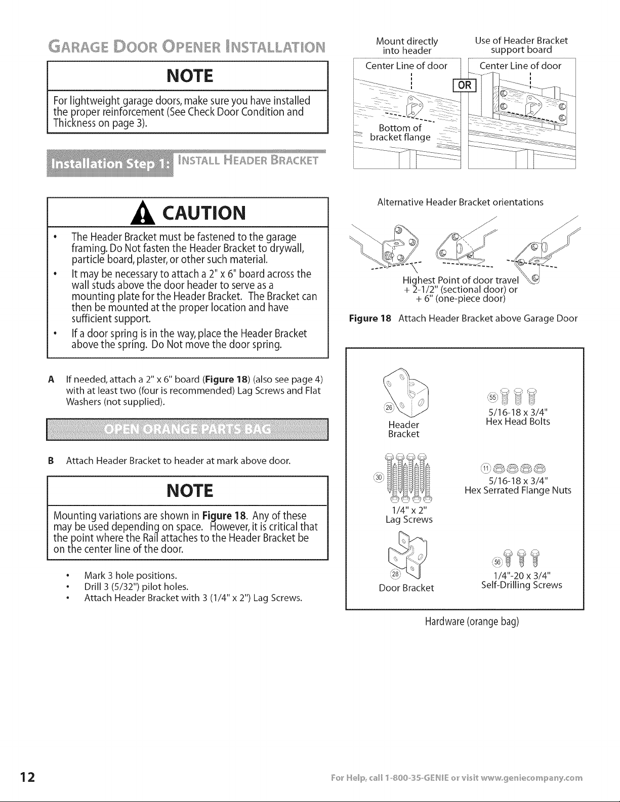
Mount directly
into header
_--____ .___ ',
7::?: : .....
Bottom of
bracket flange
Use of Header Bracket
support board
Center Line of door
I
CAUTION
o
The Header Bracket must be fastened to the garage
framing. Do Not fasten the Header Bracket to drywall,
particle board, plaster, or other such material.
• It may be necessary to attach a 2" x 6" board across the
wall studs above the door header to serve as a
mounting plate for the Header Bracket. The Bracket can
then be mounted at the proper location and have
sufficient support.
• If a door spring is in the way, place the Header Bracket
above the spring. Do Not move the door spring.
Alternative Header Bracket orientations
\
Highest Point of door travel
+ 2-1/2" (sectional door) or
+ 6" (one-piece door)
Figure 18 Attach Header Bracket above Garage Door
A If needed, attach a 2" x 6" board (Figure 18) (also see page 4)
with at least two (four is recommended) Lag Screws and Flat
Washers (not supplied).
B Attach Header Bracket to header at mark above door.
NOTE
Mounting variations are shown in Figure 18. Any of these
may be used depending on space. However, it iscritical that
the point where the Rail attaches to the Header Bracket be
on the center line of the door.
• Mark 3 hole positions.
• Drill 3 (5/32") pilot holes.
• Attach Header Bracket with 3 (1/4" x 2") Lag Screws.
Header
Bracket
'\. j _ _-_
5/16-18 x 3/4"
Hex Head Bolts
1/4"x 2"
Lag Screws
5/16-18 x 3/4"
Hex Serrated Flange Nuts
Door Bracket
1/4"-20 x 3/4"
Self-Drilling Screws
Hardware (orange bag)
CAUTION
Doors made of masonite, lightweight wood, fiberglass, metal,
or other lightweight materials must be properly braced
before mounting door Opener.
_o_ _'e<:tier_al doo_'_x
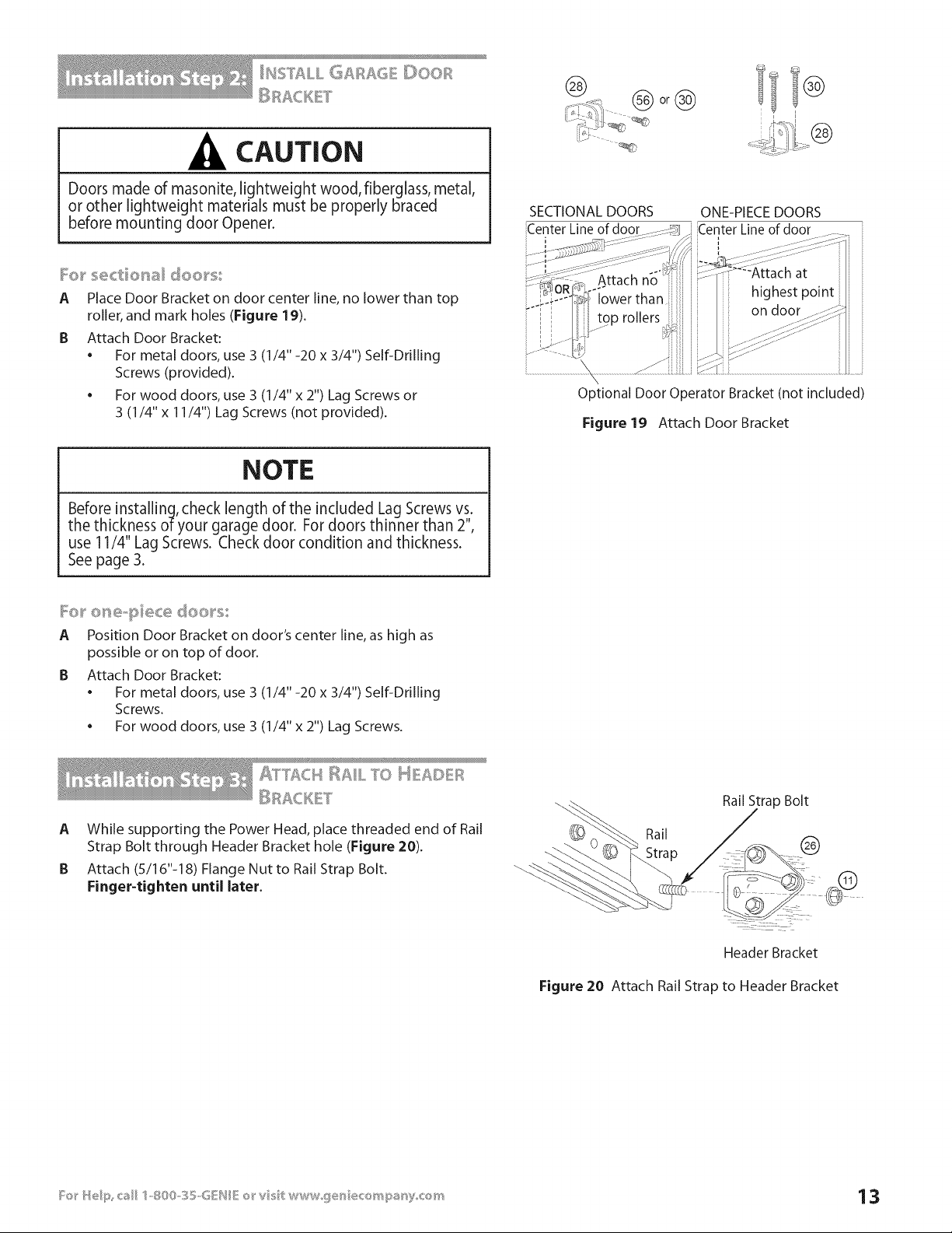
A Place Door Bracket on door center line, no lower than top
roller, and mark holes (Figure 19).
B Attach Door Bracket:
• For metal doors, use 3 (1/4" -20 x 3/4") Self-Drilling
Screws (provided).
• For wood doors, use 3 (1/4" x 2") Lag Screws or
3 (1/4" x 11/4") Lag Screws (not provided).
I®
SECTIONAL DOORS
Center Line of door
ONE-PIECE DOORS
Center Line of door
i I
Optional Door Operator Bracket (not included)
Figure 19 Attach Door Bracket
NOTE
Before installing, check length of the included Lag Screws vs.
the thickness of your garage door. For doors thinner than 2%
use 11/4" Lag Screws. Check door condition and thickness.
See page 3.
_e} _ etxe_,}::} ece doe}_5
A Position Door Bracket on door's center line, as high as
possible or on top of door.
B Attach Door Bracket:
• For metal doors, use 3 (1/4" -20 x 3/4") Self-Drilling
Screws.
. For wood doors, use 3 (1/4" x 2") Lag Screws.
A While supporting the Power Head, place threaded end of Rail
Strap Bolt through Header Bracket hole (Figure 20).
B Attach (5/16"-18) Flange Nut to Rail Strap Bolt.
Finger-tighten until later,
Rail
Rail Strap Bolt
®
Header Bracket
Figure 20 Attach Rail Strap to Header Bracket
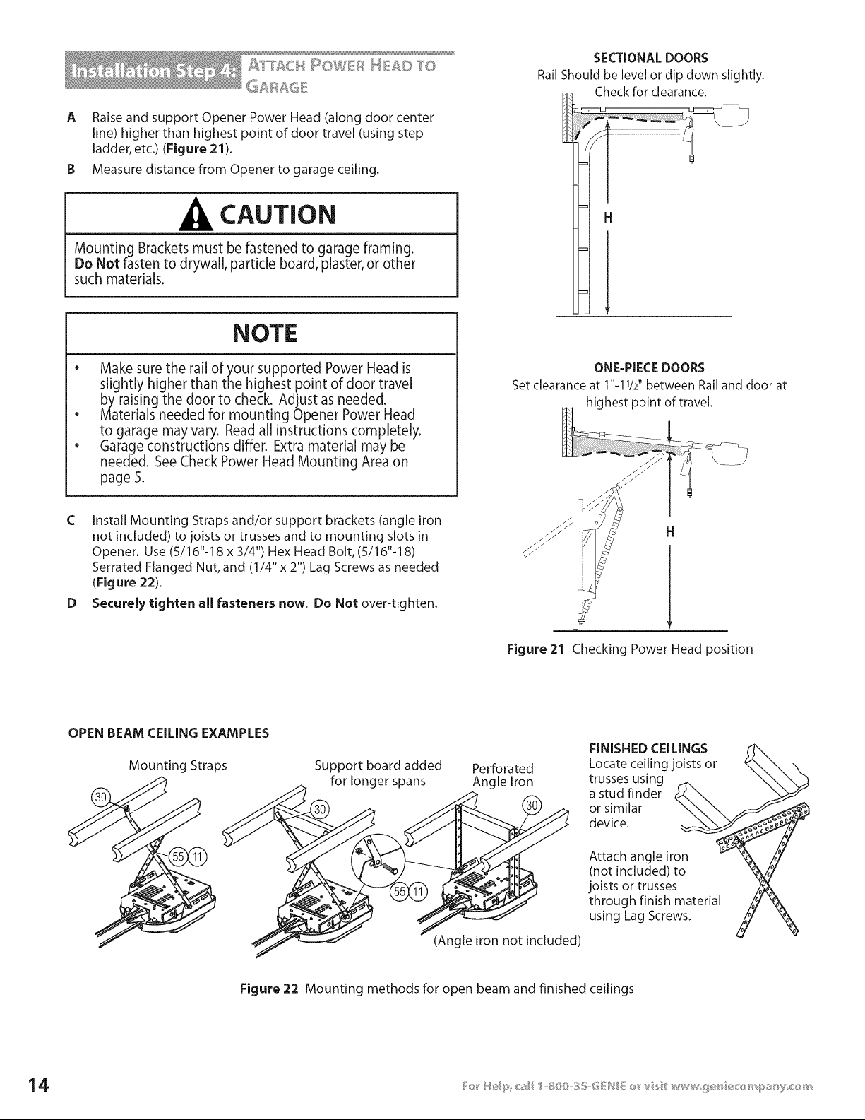
A RaiseandsupportOpenerPowerHead(alongdoorcenter
line)higherthanhighestpointofdoortravel(usingstep
ladder,etc.)(Figure21).
B Measure distance from Opener to garage ceiling.
CAUTION
Mounting Brackets must be fastened to garage framing.
Do Not fasten to drywall, particle board, plaster, or other
such materials.
NOTE
• Make sure the rail of your supported Power Head is
slightly higher than the highest point of door travel
by raising the door to check. Adjust as needed.
Materials needed for mounting Opener Power Head
to garage may vary. Read all instructions completely.
Garage constructions differ. Extra material may be
needed. See Check Power Head Mounting Area on
page 5.
SECTIONAL DOORS
Rail Should be level or dip down slightly.
Check for clearance.
H
e
e
C Install Mounting Straps and/or support brackets (angle iron
not included) to joists or trusses and to mounting slots in
Opener. Use (5/16"-18 x 3/4") Hex Head Bolt, (5/16"-18)
Serrated Flanged Nut, and (1/4" x 2") Lag Screws as needed
(Figure 22).
D Securely tighten all fasteners now. Do Not over-tighten.
ONE-PIECE DOORS
Set clearance at 1"-11/2" between Rail and door at
highest point of travel.
H
Figure 21 Checking Power Head position
OPEN BEAM CEILING EXAMPLES
Mounting Straps Support board added
for longer spans
Perforated
Angle Iron
(Angle iron not included)
FINISHED CEILINGS
Locate ceiling joists or
trusses using
a stud finder
or similar
device.
Attach angle iron
(not included) to
joists or trusses
through finish material
using Lag Screws.
Figure 22 Mounting methods for open beam and finished ceilings
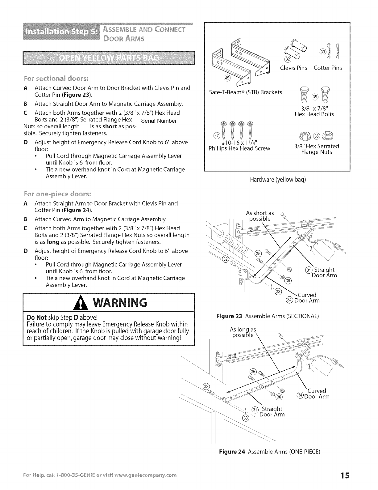
I:o_ _'sectio_al doo_'s:
A Attach Curved Door Arm to Door Bracket with Clevis Pin and
Cotter Pin (Figure 23).
B Attach Straight Door Arm to Magnetic Carriage Assembly.
C Attach both Arms together with 2 (3/8" x 7/8") Hex Head
Bolts and 2 (3/8") Serrated Flange Hex Serial Number
Nuts so overall length is as short as pos-
sible. Securely tighten fasteners.
D Adjust height of Emergency Release Cord Knob to 6' above
floor:
• Pull Cord through Magnetic Carriage Assembly Lever
until Knob is 6' from floor.
• Tie a new overhand knot in Cord at Magnetic Carriage
Assembly Lever.
I:o_ _'o_'_e-piece doo_'s
A Attach Straight Arm to Door Bracket with Clevis Pin and
Cotter Pin (Figure 24).
B Attach Curved Arm to Magnetic Carriage Assembly.
C Attach both Arms together with 2 (3/8" x 7/8") Hex Head
Bolts and 2 (3/8") Serrated Flange Hex Nuts so overall length
is as long as possible. Securely tighten fasteners.
D Adjust height of Emergency Release Cord Knob to 6' above
floor:
• Pull Cord through Magnetic Carriage Assembly Lever
until Knob is 6' from floor.
• Tie a new overhand knot in Cord at Magnetic Carriage
Assembly Lever.
WARNING
Do Not skip Step D above!
Failure to comply may leave Emergency Release Knob within
reach of children. If the Knob is pulled with garage door fully
or partially open, garage door may close without warning!
Safe-T-Beam ® (STB) Brackets
#10-16 x 11/4'.
Phillips Hex Head Screw
Clevis Pins Cotter Pins
3/8" x 7/8"
Hex Head Bolts
3/8" Hex Serrated
Flange Nuts
Hardware (yellow bag)
As short as
Figure 23 Assemble Arms (SECTIONAL)
As long as
possible
_!.(_ Straight
.... Door Arm
(_ Doo'r'Arm
Figure 24 Assemble Arms (ONE-PIECE)
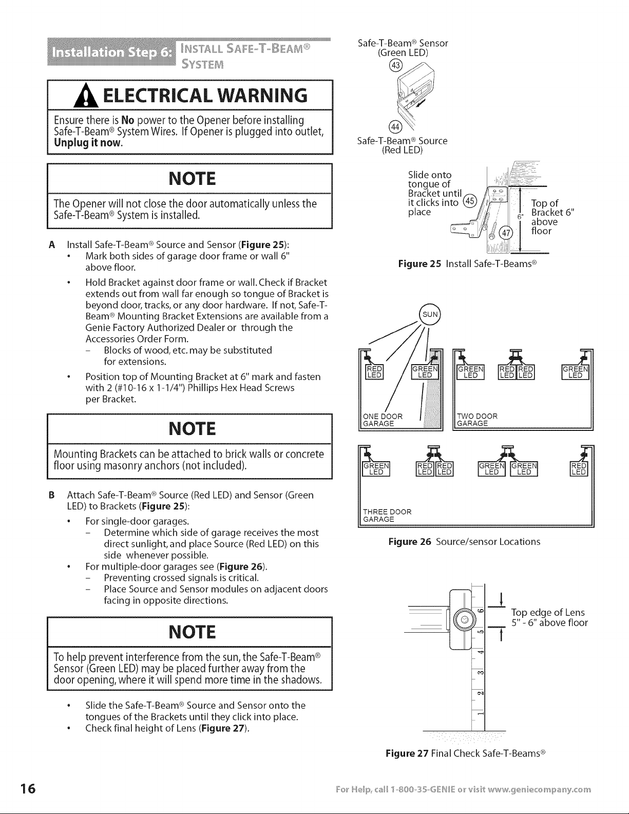
ELECTRICAL WARNING
Ensure there is No power to the Opener before installing
Safe-T-Beam® System Wires. If Opener is plugged into outlet,
Unplug it now.
NOTE
The Opener will not close the door automatically unless the
Safe-T-Beam® System is installed.
A Install Safe-T-Beam ® Source and Sensor (Figure 25):
• Mark both sides of garage door frame or wall 6"
above floor.
Hold Bracket against door frame or wall. Check if Bracket
extends out from wall far enough so tongue of Bracket is
beyond door, tracks, or any door hardware. If not, Safe-T-
Beam ® Mounting Bracket Extensions are available from a
Genie Factory Authorized Dealer or through the
Accessories Order Form.
- Blocks of wood, etc. may be substituted
for extensions.
Position top of Mounting Bracket at 6" mark and fasten
with 2 (#10-16 x 1-1/4") Phillips Hex Head Screws
per Bracket.
NOTE
Mounting Brackets can be attached to brick walls or concrete
floor using masonry anchors (not included).
B Attach Safe-T-Beam ® Source (Red LED) and Sensor (Green
LED) to Brackets (Figure 2S):
For single-door garages.
- Determine which side of garage receives the most
direct sunlight, and place Source (Red LED) on this
side whenever possible.
For multiple-door garages see (Figure 26).
- Preventing crossed signals is critical.
- Place Source and Sensor modules on adjacent doors
facing in opposite directions.
NOTE
To help prevent interference from the sun, the Safe-T-Beam®
Sensor (Green LED) may be placed further away from the
door opening, where it will spend more time in the shadows.
• ®
Slide the Safe-T-Beam Source and Sensor onto the
tongues of the Brackets until they click into place.
• Check final height of Lens (Figure 27).
Safe-T-Beam ® Sensor
(Green LED)
Safe-T-Beam ® Source
(Red LED)
Slide onto
tongue of
Bracket until._. J i:_1
it clicks into 4_//
Top
of
place !/i}i _. Bracket 6"
I above
[floor
Figure 25 Install Safe-T-Beams ®
ONE DOOR
GARAGE
TWO DOOR
GARAGE
THREEDOOR
GARAGE
Figure 26 Source/sensor Locations
Top edge of Lens
5" - 6" above floor
Figure 27 Final Check Safe-T-Beams ®
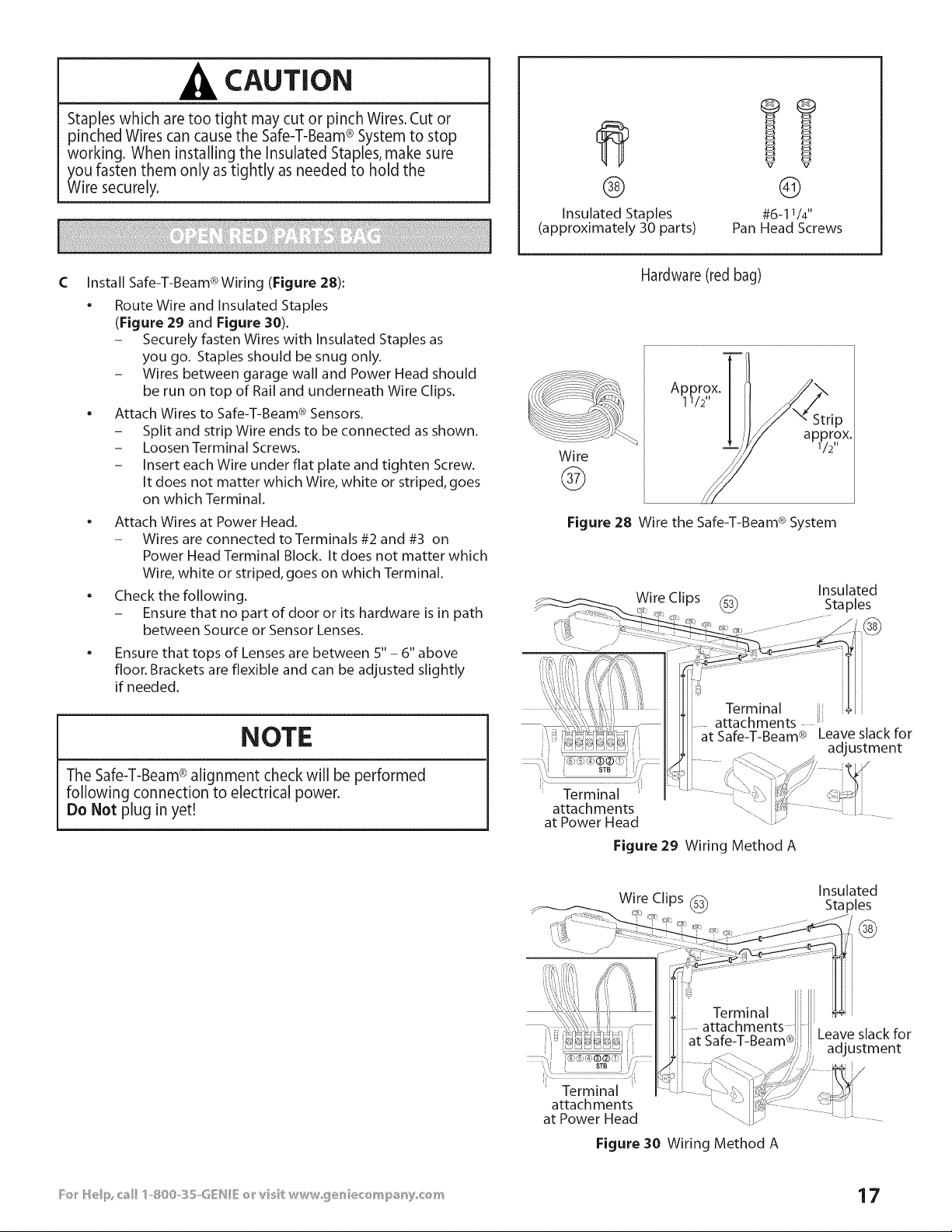
CAUTION
;taples which are too tight may cut or pinch Wires. Cut or
)inched Wires can cause the Safe-T-Beam® System to stop
working. When installing the Insulated Staples, make sure
_oufasten them only as tightly as needed to hold the
Wire securely.
®
Insulated Staples
(approximately 30 parts)
©
#6-11/4"
Pan Head Screws
C
Install Safe-T-Beam ® Wiring (Figure 28):
• Route Wire and Insulated Staples
(Figure 29 and Figure 30).
- Securely fasten Wires with Insulated Staples as
you go. Staples should be snug only.
- Wires between garage wall and Power Head should
be run on top of Rail and underneath Wire Clips.
Attach Wires to Safe-T-Beam ® Sensors.
- Split and strip Wire ends to be connected as shown.
- Loosen Terminal Screws.
- Insert each Wire under flat plate and tighten Screw.
It does not matter which Wire, white or striped, goes
on which Terminal.
• Attach Wires at Power Head.
- Wires are connected to Terminals #2 and #3 on
Power Head Terminal Block. It does not matter which
Wire, white or striped, goes on which Terminal.
Check the following.
- Ensure that no part of door or its hardware is in path
between Source or Sensor Lenses.
• Ensure that tops of Lenses are between S" - 6" above
floor. Brackets are flexible and can be adjusted slightly
if needed.
Wire
@
Hardware (red bag)
Approxi112
X,
Figure 28 Wire the Safe-T-Beam ® System
NOTE
The Safe-T-Beam®alignment check will be performed
following connection to electrical power.
Do Not plug in yet!
at Safe-T-Beam ®
Figure 29 Wiring Method A
Leave slack for
adjustment
Wire Clips (_
Insulated
Staples
@
STB j
i
Terminal
attach ments
at Power Head
at Safe-T-Beam® J
Figure 30 Wiring Method A
Leave slack for
adjustment
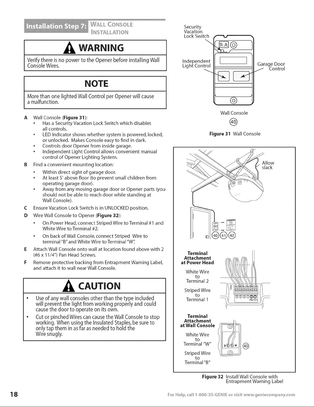
WF_LL C©BSS©L
WARNING
Verify there is no power to the Opener before installing Wall
Console Wires.
NOTE
More than one lighted Wall Control per Opener will cause
a malfunction.
A Wall Console (Figure 31):
• Has a Security Vacation Lock Switch which disables
all controls.
• LED Indicator shows whether system is powered, locked,
or unlocked. Makes Console easy to find in dark.
• Controls door Opener from inside garage.
• Independent Light Control allows convenient manual
control of Opener Lighting System.
B Find a convenient mounting location:
• Within direct sight of garage door.
• At least 5' above floor (to prevent small children from
operating garage door).
• Away from any moving garage door or Opener parts (you
should not be able to reach door while standing at
Wall Console).
C Ensure Vacation Lock Switch is in UNLOCKED position.
D Wire Wall Console to Opener (Figure 32):
• On Power Head, connect Striped Wire to Terminal #1 and
White Wire to Terminal #2.
• On back of Wall Console, connect Striped Wire to
terminal "B" and White Wire to Terminal "W'[
E Attach Wall Console onto wall at location found above with 2
(#6 x 11/4") Pan Head Screws.
F Remove protective backing from Entrapment Warning Label,
and attach it to wall near Wall Console.
CAUTION
e
Use of any wall consoles other than the type included
will prevent the light from working properly and could
cause the door to operate on its own.
Cut or pinched Wires can cause the Wall Console to stop
working. When using the Insulated Staples, be sure to
only tap them in as far as needed to hold the
Wire snugly.
Security
Vacation
Lock Switch
Independent
Light Control
1
[ I
Garage Door
J Control
©
Wall Console
@
Figure 31 Wall Console
Allow
slack
®®@
Terminal
Attachment
at Power Head
White Wire
to
Terminal 2
Striped Wire
to
Terminal 1
Terminal
Attachment
at Wall Console
White Wire
to
Terminal "W"
Striped Wire
to
Terminal "B"
®
Figure 32 Install Wall Console with
Entrapment Warning Label
Co_s_scs__sG_ovv_
ELECTRICAL WARNING
e
A
To reduce the risk of electrical shock, this equipment has
a grounding type Plug that has a third (grounding) Pin.
This Plug will only fit into a grounding type outlet. If the
Plug does not fit into the outlet, contact a qualified
electrician to install the proper outlet. Do Not change
the Plug in any way.The door Opener must be properly
grounded to prevent personal injury and damage to the
components.
The electrical power to the door Opener Must Be removed
when the Motor Cover is removed. Electrical power must
remain off while making electrical connections.
Check building codes:
• If building code requires Opener be permanently wired
to building, have a licensed electrician perform step B.
• If you are not installing permanent wiring, go to step C.
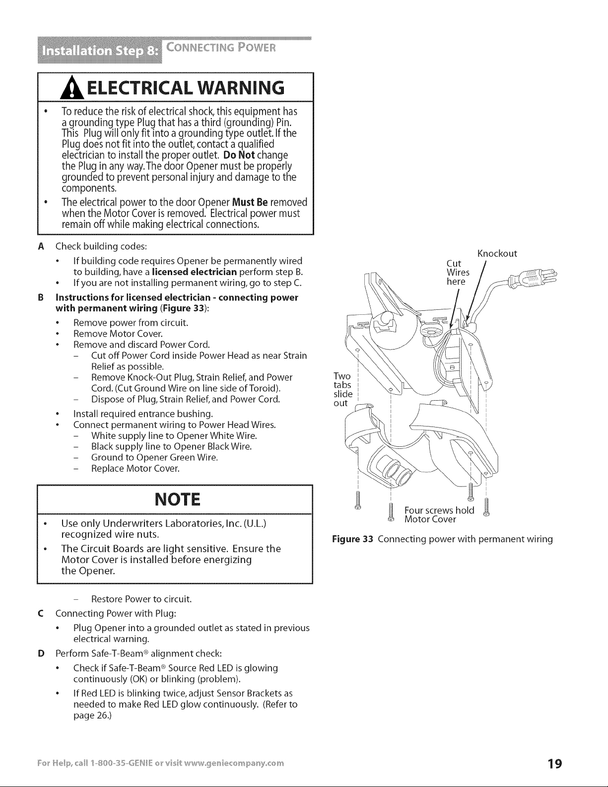
Instructions for licensed electrician - connecting power
with permanent wiring (Figure 33):
• Remove power from circuit.
• Remove Motor Cover.
• Remove and discard Power Cord.
- Cut off Power Cord inside Power Head as near Strain
Relief as possible.
- Remove Knock-Out Plug, Strain Relief, and Power
Cord. (Cut Ground Wire on line side of Toroid).
- Dispose of Plug, Strain Relief, and Power Cord.
• Install required entrance bushing.
• Connect permanent wiring to Power Head Wires.
- White supply line to Opener White Wire.
- Black supply line to Opener Black Wire.
- Ground to Opener Green Wire.
- Replace Motor Cover.
NOTE
e
Use only Underwriters Laboratories, Inc. (U.L.)
recognized wire nuts.
The Circuit Boards are light sensitive. Ensure the
Motor Cover is installed before energizing
the Opener.
Knockout
Cut
Wires
here
Two
tabs
slide
out
I
Four screws hold
Motor Cover
Figure 33 Connecting power with permanent wiring
C
D
- Restore Power to circuit.
Connecting Power with Plug:
• Plug Opener into a grounded outlet as stated in previous
electrical warning.
Perform Safe-T-Beam ® alignment check:
• Check if Safe-T-Beam ® Source Red LED is glowing
continuously (OK) or blinking (problem).
• If Red LED is blinking twice, adjust Sensor Brackets as
needed to make Red LED glow continuously. (Refer to
page 26.)
5elX@_{_ of Limt 5w t@_®s
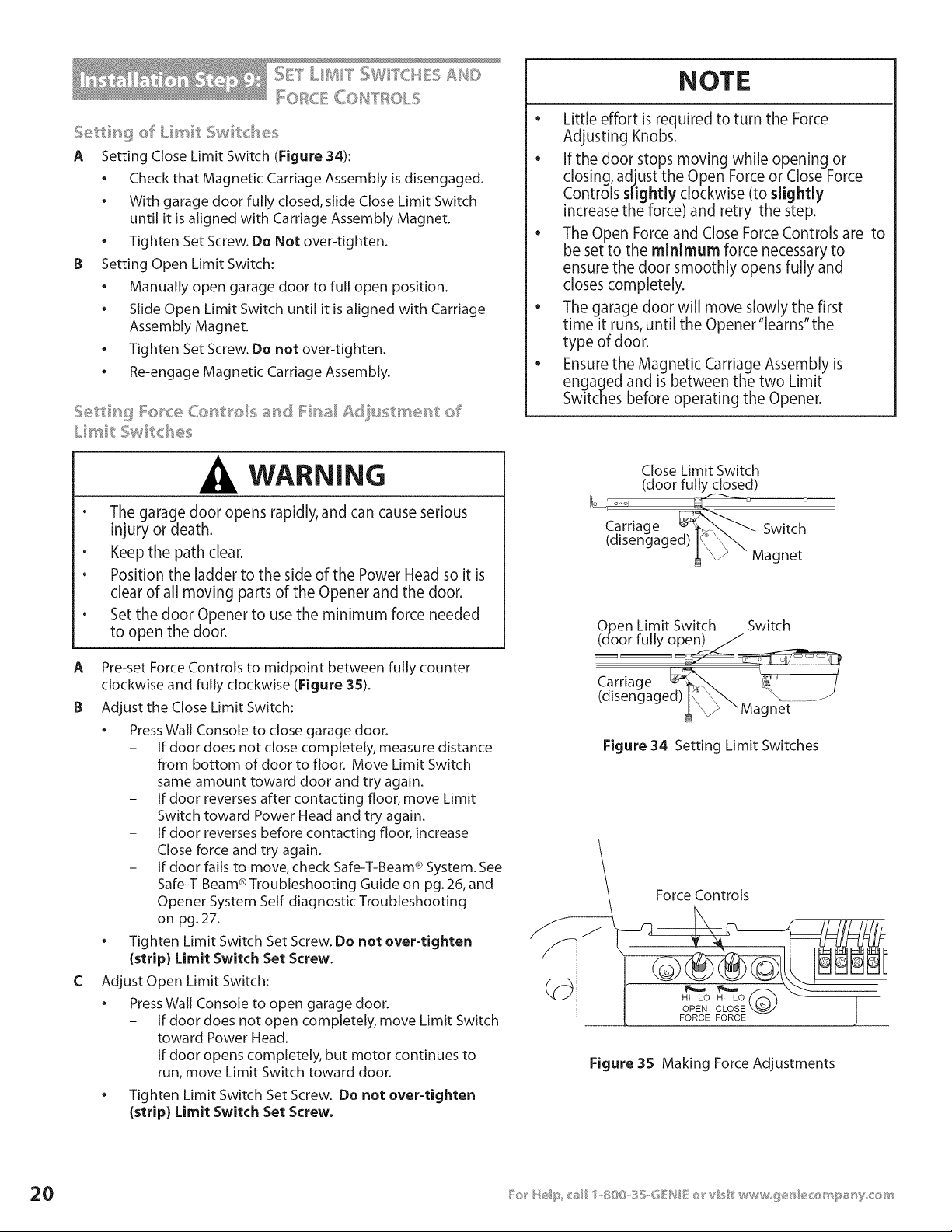
A Setting Close Limit Switch (Figure 34):
• Check that Magnetic Carriage Assembly is disengaged.
• With garage door fully closed, slide Close Limit Switch
until it is aligned with Carriage Assembly Magnet.
• Tighten Set Screw. Do Not over-tighten.
B Setting Open Limit Switch:
• Manually open garage door to full open position.
• Slide Open Limit Switch until it is aligned with Carriage
Assembly Magnet.
• Tighten Set Screw. Do not over-tighten.
. Re-engage Magnetic Carriage Assembly.
WARNING
• The garage door opens rapidly, and can cause serious
injury or death.
• Keep the path clear.
• Position the ladder to the side of the Power Head so it is
clear of all moving parts of the Opener and the door.
• Set the door Opener to use the minimum force needed
to open the door.
A Pre-set Force Controls to midpoint between fully counter
clockwise and fully clockwise (Figure 35).
B Adjust the Close Limit Switch:
* Press Wall Console to close garage door.
- If door does not close completely, measure distance
from bottom of door to floor. Move Limit Switch
same amount toward door and try again.
- If door reverses after contacting floor, move Limit
Switch toward Power Head and try again.
- If door reverses before contacting floor, increase
Close force and try again.
- If door fails to move, check Safe-T-Beam ® System. See
Safe-T-Beam ® Troubleshooting Guide on pg. 26, and
Opener System Self-diagnostic Troubleshooting
on pg. 27.
. Tighten Limit Switch Set Screw. Do not over-tighten
{strip) Limit Switch Set Screw.
C Adjust Open Limit Switch:
. Press Wall Console to open garage door.
- If door does not open completely, move Limit Switch
toward Power Head.
- If door opens completely, but motor continues to
run, move Limit Switch toward door.
. Tighten Limit Switch Set Screw. Do not over-tighten
{strip) Limit Switch Set Screw.
NOTE
o
Little effort is required to turn the Force
Adjusting Knobs.
• If the door stops moving while opening or
closing, adjust the Open Force or Close Force
Controls slightly clockwise (to slightly
increase the force) and retry the step.
• The Open Force and Close Force Controls are to
be set to the minimum force necessary to
ensure the door smoothly opens fully and
closes completely.
• The garage door will move slowly the first
time it runs, until the Opener"learns"the
type of door.
• Ensure the Magnetic Carriage Assembly is
engaged and is between the two Limit
Switches before operating the Opener.
Close Limit Switch
(door fully closed)
Carriage _'_ Switch
(disengaged) I% _ Magnet
Open Limit Switch Switch
(door fully open)/
Carriage
(disengaged) IC \\ "\ ....J
_ " Magnet
Figure 34 Setting Limit Switches
Force Controls
HI LO
OPEN CLOSE X.._
FORCE FORCE
Figure 35 Making Force Adjustments
NOTE
e
To protect your new investment, your Excelerator ® is
equipped with a Timer and Cycle Counter which work
together to prevent any chance of heat damage to
electrical circuits caused by too many cycles in too short
a time. If your Opener suddenly stops responding to the
Wall Console- Do Not Unplug the Unit- simply wait
10 minutes for the Timer/Cycle Counter to reset itself
and try again.
Unplugging the unit will prevent the Timer/Cycle
Counter from resetting.
D Test Door Opener:
• Run door up and down a few times using Wall Console
and observe door travel.
• Repeat steps above as needed to set Limit
Switch positions.
E Adjust Open Force to minimum needed:
• Place door in closed position using Wall Console.
• Gently adjust Open Force fully counterclockwise
(minimum force).
• Run Opener using Wall Console.
• Observe that door runs to Open Limit Switch.
- If not, adjust Open Force Control slightly clockwise,
close garage door, and open it again.
• Repeat steps above until garage door runs smoothly
from Close Limit Switch to Open Limit Switch.
F Adjust Close Force to minimum needed:
• Place door in open position using Wall Console.
• Gently adjust Close Force fully counterclockwise
(minimum force).
• Run Opener using Wall Console.
• Observe that door runs to Close Limit Switch.
- If not, adjust Close Force Control slightly clockwise,
open garage door, and close it again.
. Repeat steps above until garage door runs smoothly
from Open Limit Switch to Close Limit Switch.
c _°-= _ =_¢_=_c =_
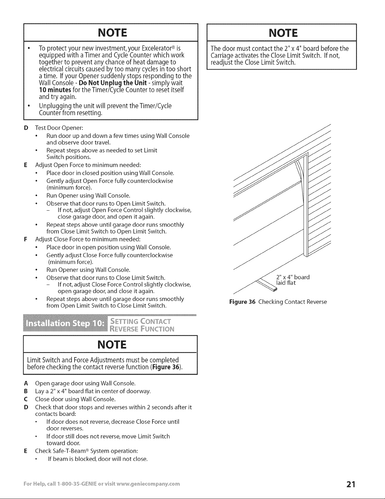
NOTE
Limit Switch and Force Adjustments must be completed
before checking the contact reverse function (Figure 38).
A Open garage door using Wall Console.
B Lay a 2" x 4" board flat in center of doorway.
C Close door using Wall Console.
D Check that door stops and reverses within 2 seconds after it
contacts board:
o If door does not reverse, decrease Close Force until
door reverses.
o If door still does not reverse, move Limit Switch
toward door.
E Check Safe-T-Beam ® System operation:
o If beam is blocked, door will not close.
NOTE
The door must contact the 2"x 4" board before the
Carriage activates the Close Limit Switch. If not,
readjust the Close Limit Switch.
2" x 4" board
laid flat
Figure 36 Checking Contact Reverse
_ _OY _ COH]'ROL
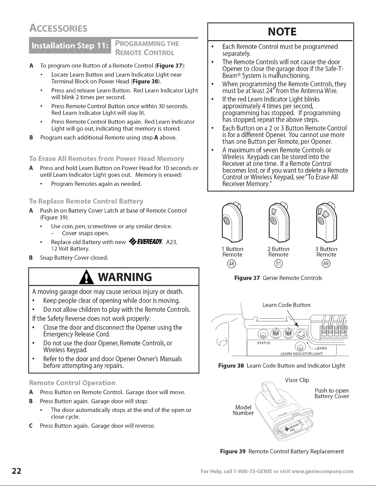
A To program one Button of a Remote Control (Figure 37):
• Locate Learn Button and Learn Indicator Light near
Terminal Block on Power Head (Figure 38).
• Press and release Learn Button. Red Learn Indicator Light
will blink 2 times per second.
• Press Remote Control Button once within 30 seconds.
Red Learn Indicator Light will stay lit.
• Press Remote Control Button again. Red Learn Indicator
Light will go out, indicating that memory is stored.
B Program each additional Remote using step A above.
7b E_'ase Ail .......... _,,
_essetes frown Re e_" Mea_t BJ]e_'_'_ery
A Press and hold Learn Button on Power Head for 10 seconds or
until Learn Indicator Light goes out. Memory is erased:
. Program Remotes again as needed.
NOTE
e
Each Remote Control must be programmed
separately.
• The Remote Controls will not cause the door
Opener to close the garage door if the Safe-T-
Beam® System is malfunctioning.
• When programming the Remote Controls, they
must be at least 24" from the Antenna Wire.
• Ifthe red Learn Indicator Light blinks
approximately 4 times per second,
programming has stopped. If programming
has stopped, repeat the above steps.
Each Button on a 2 or 3 Button Remote Control
is for a different Opener. You cannot use more
than one Button per Remote, per Opener.
• A maximum of seven Remote Controls or
Wireless Keypads can be stored into the
Receiver at one time. If a Remote Control
becomes lost, or if you want to delete a Remote
Control or Wireless Keypad, see "To EraseAll
Receiver Memory."
A Push in on Battery Cover Latch at base of Remote Control
(Figure 39):
Use coin, pen, screwdriver or any similar device.
- Cover snaps open.
Replace old Battery with new _EI/_'RE/ID_, A23,
12 Volt Battery.
B Snap Battery Cover closed.
WARNING
A moving garage door may cause serious injury or death.
• Keep people clear of opening while door is moving.
• Do not allow children to play with the Remote Controls.
If the Safety Reverse does not work properly:
• Close the door and disconnect the Opener using the
Emergency Release Cord.
• Do not use the door Opener, Remote Controls, or
Wireless Keypad.
• Refer to the door and door Opener Owner's Manuals
before attempting any repairs.
A Press Button on Remote Control. Garage door will move.
B Press Button again. Garage door will stop:
• The door automatically stops at the end of the open or
close cycle.
C Press Button again. Garage door will reverse.
@@@
1 Button 2 Button 3 Button
Remote Remote Remote
® ® ®
Figure 37 Genie Remote Controls
J
Learn Code Button
LEARN INDICATOR LIGHT
Figure 38 Learn Code Button and Indicator Light
Visor Clip
Model
Number
\\
Push to open
Battery Cover
Figure 39 Remote Control Battery Replacement
WARNING
A Moving door can cause serious injury or death.
1 Keep people clear of opening while door is moving.
2 Do Not allow children to play with Wireless Keypad.
3 During programming, the door opener could begin
to run, so stay away from the moving door and its
parts.To keep the door from moving, dose the door
and disconnect it from the Openerby pulling the
Emergency Release.
If Safety Reverse does not work properly
1 Close door and disconnect the Opener using
Emergency Release Cord.
2 Do not use door Opener, Remote Controls, or
Wireless Keypad.
3 Refer to Door and Door Opener Owner's Manuals
before attempting any repairs.
NOTE
FOR CONVENIENCE-- Program Keypad BEFOREmounting.
A Set Wireless Keypad PIN (Personal ID Number):
• Activate programming mode.
C
o
o
- Press (in order)
- Red LEDblinks - once per second.
Enteryour PIN(3to 8 characters).
Press
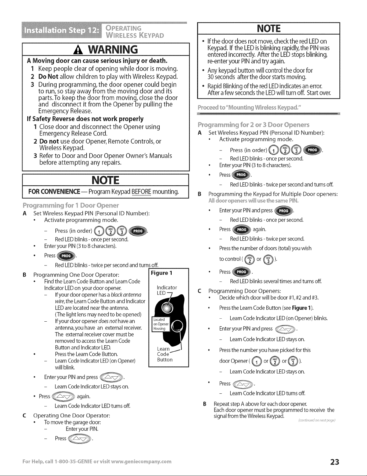
Programming One Door Operator:
• Find the Learn Code Button and Learn Code
Indicator LEDon your door opener.
- Ifyour door opener has a black antenna
wire,the Learn Code Button and Indicator
LEDare located near the antenna.
(The light lens may need to be opened)
- Ifyour door opener doesnot have an
antenna, you have an external receiver.
The external receiver cover must be
removed to accessthe Learn Code
Button and Indicator LED.
• Pressthe Learn Code Button.
- LearnCode Indicator LED(on Opener)
will blink.
Enteryour PINand press _.
- Learn Code Indicator LEDstays on.
• Press_
again.
- Learn Code Indicator LEDturns off.
RedLEDblinks-twice persecondandturnsoff.
Figure 1
Indicator
Lea rnj_
Code--
Button
Operating One Door Operator:
• To move the garage door:
- Enteryour PIN.
- PressC@.
NOTE
e
If the door does not move, check the red LED on
Keypad. If the LED is blinking rapidly, the PINwas
entered incorrectly. After the LEDstops blinking,
re-enter your PIN and try again.
Any keypad button will control the door for
30 seconds after the door starts moving.
Rapid Blinking of the red LEDindicates an error.
After a few seconds the LEDwill turn off. Start over.
A Set Wireless Keypad PIN (Personal ID Number):
Activate programming mode.
- Press(in order) )).
- Red LEDblinks - once per second.
• Enter your PIN (3to 8 characters).
• Press )).
- Red LEDblinks- twice per second and turns off.
B Programming the Keypad for Multiple Door openers:
• Enter your PIN and press }.
- Red LEDblinks - once per second.
• Press again.
- Red LEDblinks - twice per second.
• Pressthe number of doors (total) you wish
to control (@ or @).
• Press ).
- Red LEDblinks several times and turns off.
C Programming Door Openers:
Decide which door will be door #1,#2 and #3.
Pressthe Learn Code Button (see Figure 1).
- Learn Code Indicator LED(on Opener) blinks.
• Enter your PIN and press _.
- Learn Code Indicator LEDstays on.
Pressthe number you have picked for this
door Opener(@ or @ or @).
- Learn Code Indicator LEDstays on.
" Press _.
- Learn Code Indicator LEDturns off,
B Repeat step A above for each door opener,
Eachdoor opener must be programmed to receive the
signal from the Wireless Keypad,
oi _ ;5 0
P_'eg_a_ss'@_¢_ fe_' 2 o__3 Doe_ _Ope_e_'s (Continued)
A Operating 2 or 3 Door Openers:
• Tomoveoneof the doors.
• Enteryour PIN.
• Press
• Pressdoor openernumber (@ or @ or@ ).
t&_OUHTH6 HSW_U('?_OHS
T_seI_ypad m_S be mo_,_ ted _ssght _£'the _:_00(s st/(}ast 5 feet
above tB® g_ouhd _hd c/e_'__d _r%zmevhg doo_' pats,,
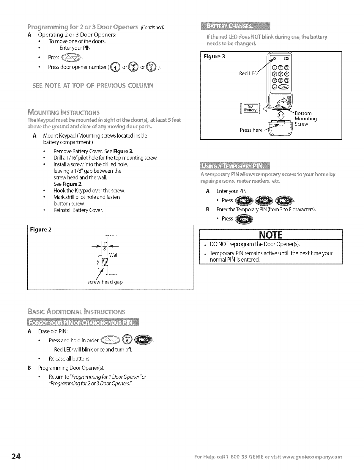
A Mount Keypad.(Mounting screwslocated inside
battery compartment.)
• Remove Battery Cover. See Figure 3.
• Drill a 1/16" pilot hole for the top mounting screw.
• install a screw into the drilled hole,
leaving a 1/8" gap between the
screw head and the wall.
SeeFigure 2.
• Hook the Keypad over the screw.
Mark, drill pilot hole and fasten
bottom screw.
Reinstall Battery Cover.
Figure 2
1"
screw head gap
Figure 3
Red LED
Bottom
X/Mounting
Presshere Screw
NOTE
. DO NOT reprogram the Door Opener(s).
. Temporary PIN remains active until the next time your
normal PIN is entered.
_ _ _ _ _%_c_ _c
A Eraseold PIN:
• Pressand hold in order @_--_
- Red LEDwill blink once and turn off.
• Releaseall buttons.
Programming Door Opener(s).
• Return to"Programming for 1Door Opener"or
"Programming for2 or 3 Door Openers."
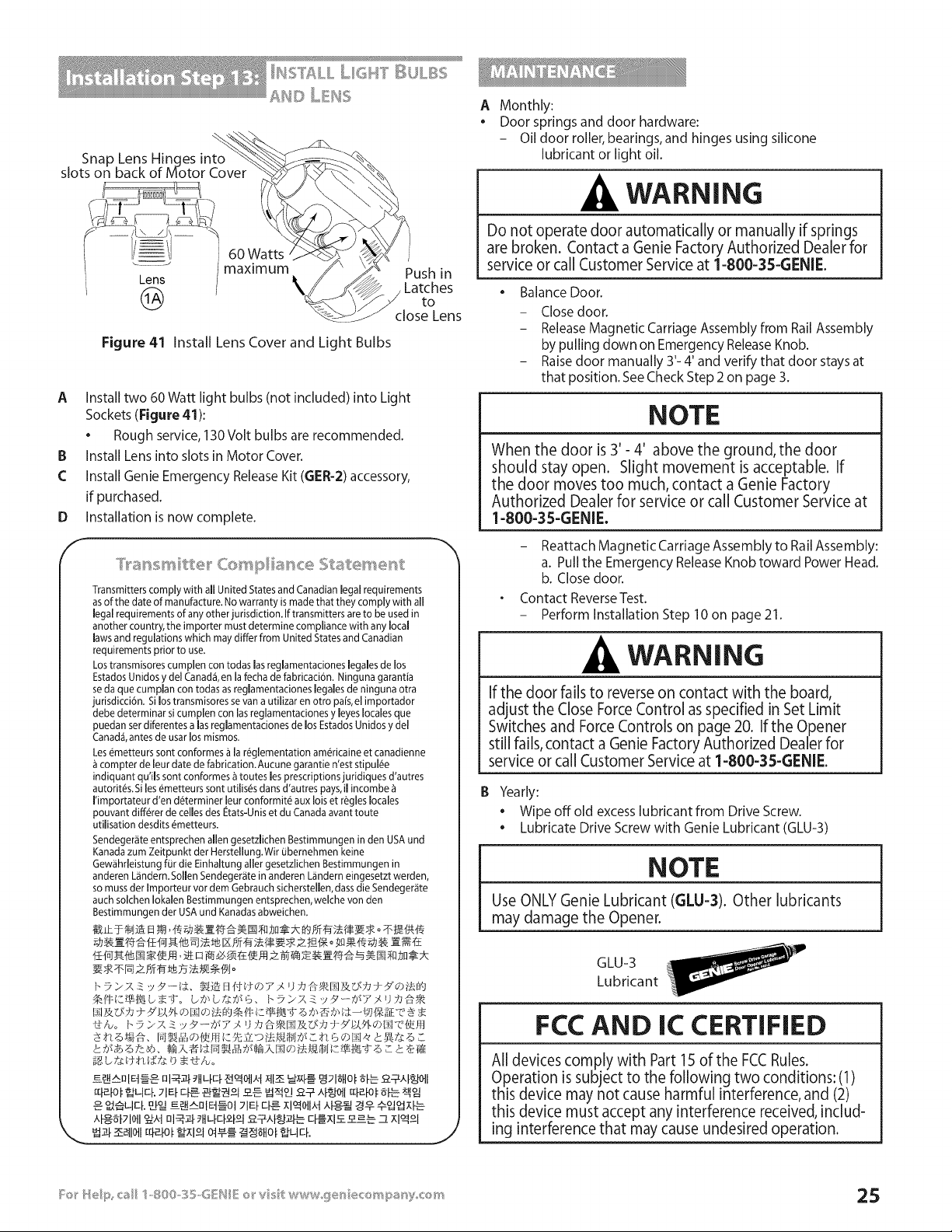
Snap Lens Hinges into
slots on back of Motor Cover
Lens
@
60 Watts
maximum
Figure 41 Install Lens Cover and Light Bulbs
Push in
Latches
to
close Lens
A Install two 60 Watt light bulbs (not included) into Light
Sockets (Figure 41):
• Rough service, 130 Volt bulbs are recommended.
IB Install Lens into slots in Motor Cover.
£ Install Genie Emergency Release Kit (GER-2) accessory,
if purchased.
Installation is now complete.
D
f
Transmitters comply with all United States and Canadian legal requirements
asof the date of manufacture. No warranty is made that they comply with all
legal requirements of any other jurisdiction. If transmitters are to be used in
another country, the importer must determine compliance with any local
laws and regulations which may differ from United States and Canadian
requirements prior to use.
Los transmisores cumplen con todas las reglamentaciones legales de los
Estados Unidos y del Canad& en la fecha de fabricaci6n. Ninguna garantia
se da que cumpJan con todas as reglamentaciones legaJesde ninguna otra
jurisdicci6n. Si los transmisores se van a utilizar en otro pais, el importador
debe determinar si cumplen con las reglamentaciones y byes locales que
puedan ser diferentes alas reglamentaciones de los Estados Unidos y del
Canad4, antes de usar los mismos.
Les e_metteurssont conformes & la re_glementation am_ricaine et canadienne
compter de leur date de fabrication. Aucune garantie n'est stipul@
indiquant qu'iJs sont conformes _ toutes les prescriptions juridiques d'autres
autorit_s. Si les _metteurs sont utilis@sdans d'autres pays, il incombe
I'importateur d'en d_terminer leur conformit_ aux lois et r@gleslocales
pouvant diff@rerde celles des Etats-Unis et du Canada avant toute
utiJisation desdits _metteurs.
Sendeger_ite entsprechen allen gesetzlichen Bestimmungen in den USA und
Kanada zum Zeitpunkt der Herstellung.Wir ubemehmen keine
Gew_ihrleistung for die Einhaltung alJergesetzlichen Bestimmungen in
anderen L_ndern. SolJenSendeger_te in anderen L_inderneingesetzt werden,
so muss der Importeur vor dem Gebrauch sicherstellen, dass die Sendeger_ite
auch solchen Iokalen Bestimmungen entsprechen, welche von den
Bestimmungen der USA und Kanadasabweichen.
_igb £_:d-,td,g:£_ b • 1-I_,o
J
A Monthly:
Door springs and door hardware:
- Oil door roller, bearings, and hinges using silicone
lubricant or light oil.
WARNING
Do not operate door automatically or manually if springs
are broken. Contact a Genie Factory Authorized Dealer for
service or call Customer Service at 1-800-35-GENIE.
• Balance Door.
- Closedoor.
- ReleaseMagnetic Carriage Assembly from Rail Assembly
by pulling down on EmergencyReleaseKnob.
- Raise door manually 3'- 4' and verify that door stays at
that position. See Check Step 2 on page 3.
NOTE
When the door is 3'- 4' above the ground, the door
should stay open. Slight movement is acceptable. If
the door moves too much, contact a Genie Factory
Authorized Dealer for service or call Customer Service at
1-800-35-GENIE.
- Reattach Magnetic Carriage Assembly to Rail Assembly:
a. Pull the Emergency Release Knob toward Power Head.
b. Close door.
Contact Reverse Test.
- Perform Installation Step 10 on page 21.
WARNING
If the door fails to reverse on contact with the board,
adjust the Close Force Control as specified in Set Limit
Switches and Force Controls on page 20. If the Opener
still fails, contact a Genie Factory Authorized Dealer for
service or call Customer Service at 1-800-35-GENIE.
IB Yearly:
• Wipe off old excess lubricant from Drive Screw.
• Lubricate Drive Screw with Genie Lubricant (GLU-3)
NOTE
Use ONLY Genie Lubricant (GLU=3). Other lubricants
may damage the Opener.
GLU-3
Lubricant
FCC AND IC CERTIFIED
All devices comply with Part lS of the FCCRules.
Operation is subject to the following two conditions: (1)
this device may not cause harmful interference, and (2)
this device must accept any interference received, includ-
ing interference that may cause undesired operation.

TO
.41LWARNING
REDUCE THE RiSK OF SEVERE iNJURY OR DEATH
1 READAND FOLLOW ALL INSTRUCTIONS.
2 Never let children operate or play with the Door Controls. Keep the Remote Control away from children.
3 Always keep the moving door in sight and away from people and objects until the door is completely closed.
NO ONE SHOULD CROSSTHE PATH OF THE MOVING DOOR.
4 NEVERGO UNDER A STOPPED,PARTIALLYOPEN DOOR.
5 Test Opener monthly'. The door MUST reverse on contact with a 1-1/2" high object (or a 2" x 4" board laid flat)
at the center of the doorway on the floor. After adjusting either the Force or the Limit of travel, retest the Door
Opener. Failure to adjust the Opener properly may cause severe injury or death.
6 When possible use the Emergency Release only when the door is closed. Use caution when using this Release
with the door open. Weak or broken springs are capable of increasing the rate of door closure and increasing
the risk of severe injury or death.
7 KEEPGARAGE DOORS PROPERLYBALANCED. See Owner's Manual. An improperly balanced door increases the
risk of severe injury or death. Have a Genie Factory Authorized Dealer make repairs to cables, spring
assemblies, and other hardware.
8 SAVETHESEINSTRUCTIONS.
. WARNING
Usethe Wall Console included with Opener. Any other wall console can cause the Opener to operate unexpectedly and
the light to stop working.
TI!;,IOUBLESHOOTI ' ....
Source (Red LED) Sensor (Green LED) Possible Problem Solution
ON ON Normal operation None required
- Power Head not powered - Check breakers, fuses, plugs
OFF OFF
• Wiring from Power Head bad • Check wiring for obvious shorts
OFF ON
2 BLINKS, Pause
(Repeat)
2 BLINKS, Pause
(Repeat)
3 BLINKS, Pause
(Repeat)
4 BLINKS, Pause
(Repeat)
ON
OFF
ON
- Wiring to Source missing or bad
• Power has been interrupted
- Beam not aligned
• Beam obstructed
• Sensor defective
- Wire to Sensor missing or bad
• Sensor defective
- Check wiring
• Remove power and reapply
- Check Source, Sensor alignment
- Check for obstruction
• Contact Customer Service
- Check wiring
• Contact Customer Service
• Sensor receiving interference - Determine source of interference
• Contact Customer Service
- Source not sending pulses - Contact Customer Service
ON • Source defective • Contact Customer Service

• See Status Light on Figure38, page 22)
You See
1 BLINK,
Pause
(Repeat)
2 BLINKS,
Pause
(Repeat)
3 BLINKS,
Pause
(Repeat)
4 BLINKS,
Pause
(Repeat)
SBLINKS,
Pause
6 BLINKS,
Pause
7 BLINKS,
Pause
Problem
Motor Drive
Board
Normal
operation
restored
If the problem
recurs
Operation not
restored
Controller
Board
Interrupt
Opener
Overheated
or
Force Settings
Incorrect
Safe-T-Beam ®
Malfunction
Wall Console
does not work
Limit Switches
not working
What to Do
. Reset Opener--unplug (or disconnect power), wait 5 seconds, plug
back in (reapply power), and activate from Wall Console.
. First Cycle will run at slow speed.
Reference
. Check door condition. NOTE:This Opener is equipped with an
automatic garage door balance detection system. An improperly
balanced door, damaged or worn counter-balance spring, binding
door hardware or rollers may result in a "ONE-BLINK" signal,
• Contact Customer Service for further assistance.
. Checkdoor condition.
. Have a Genie Factory Authorized Dealer check:
- Fuse on Motor Drive Board.
- Ribbon Cable on Motor Drive Board is properly inserted into
Connector on Controller Board.
. Contact Customer service for further service.
. Reset Opener -- unplug (or disconnect power), wait S seconds, plug
back in (reapply power), and activate from Wall Console.
. Have a Genie Factory Authorized Dealer check that Ribbon Cable on
Motor Board is properly inserted into connector on Controller Board.
. Contact Customer Service for further assistance.
. Do not unplug or disconnect power from Opener.Wait 10 minutes
for internal clock to provide additional cycles. Cycles are restored
at a rate of S cycles per 10 minutes of rest.
. Check Force Settings. NOTE: Force Settings are not pre-set at factory.
. Checkdoor condition.
. Contact Customer service for further assistance.
. Check Safe-T-Beam ® Self-diagnostic System. NOTE: Safe-T-Beam ®
System must be installed and operational to enable door to close,
• Contact Customer Service for further assistance.
. Check Wall Console Wiring for shorts, tight Staples, or pinched Wires.
. Check Wiring Connections at Power Head and Wall Console.
Contact Customer Service for further assistance
. Check Limit Switch Wire connections to Terminals on Power Head.
. Check for shorted or pinched Wires under Limit Switch Brackets.
. Contact Customer Service for further assistance.
. Vacation Locking Switch on Wall Control is in"Lock" mode.
Unlock switch.
. Contact Customer Service for further assistance.
See Door
Safety Guide
1. See page 3.
2. See door
Safety Guide
1. See page 20.
2. See Door
See page 16.
See page 18.
See page 20.
8 BLINKS, Wall Console See page 18
Pause locked
(Repeat)
NOTE
• The status LED Indicator Light is located under the Lens Cover.The Green LED light will turn ON, then OFF when
power is applied to the Opener. If LED stays ON, have a Genie Factory Authorized Dealer check the Controller
Board, or call Customer Service at 1-800-35-GENIE.
• If Safe-T-Beam® problems exists, the door can be closed electrically by holding the Wall Console Button down
until door is fully closed.
• The Remote Controls and Wireless Keypad will not work without a working Safe-T-Beam® System.
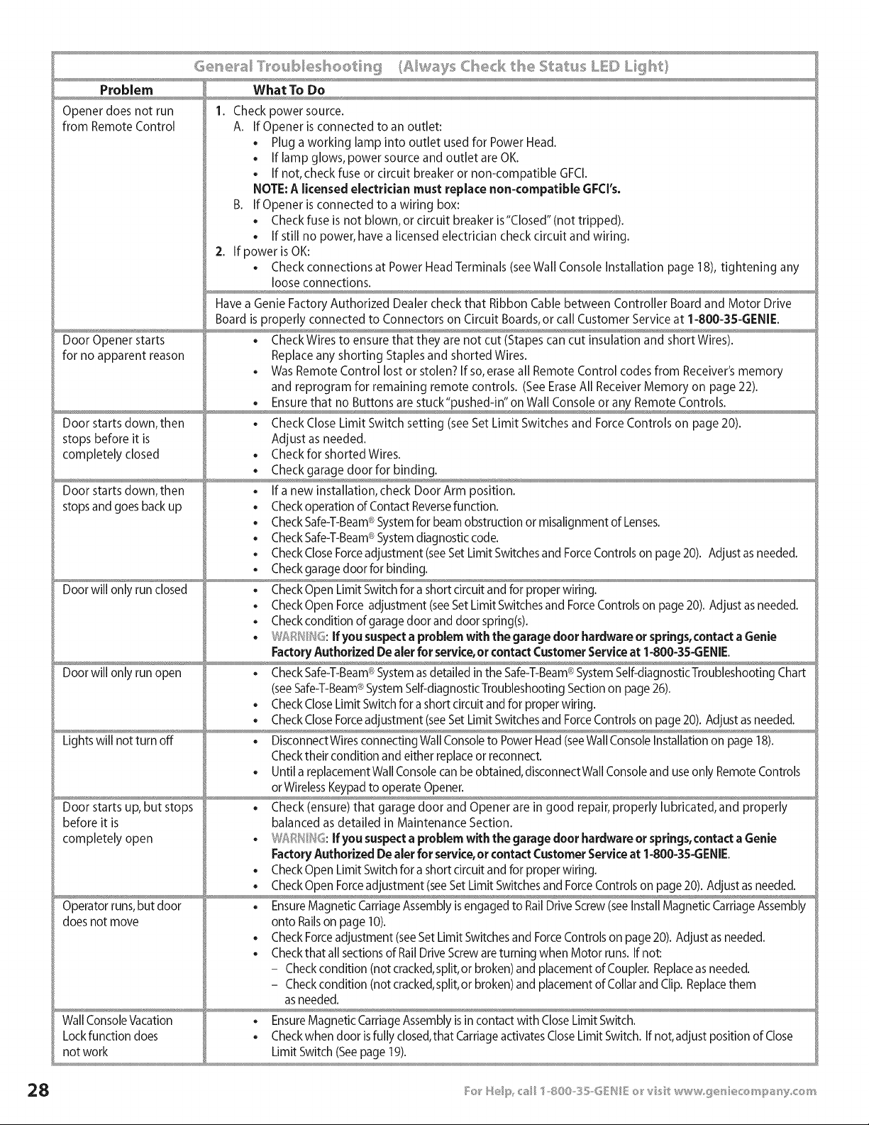
Problem What To Do
Opener does not run 1. Check power source.
from Remote Control A. If Opener is connected to an outlet:
• Plug a working lamp into outlet used for Power Head.
• If lamp glows, power source and outlet are OK.
. If not, check fuse or circuit breaker or non-compatible GFCl.
NOTE: A licensed electrician must replace non-compatible GFCI's.
B. If Opener is connected to a wiring box:
. Check fuse is not blown, or circuit breaker is"Closed" (not tripped).
. If still no power, have a licensed electrician check circuit and wiring.
2. If power is OK:
. Check connections at Power Head Terminals (seeWall Console Installation page 18), tightening any
loose connections.
Have a Genie Factory Authorized Dealer check that Ribbon Cable between Controller Board and Motor Drive
Board is properly connected to Connectors on Circuit Boards, or call Customer Service at 1-800-3S-GENIE.
Door Opener starts . Check Wires to ensure that they are not cut (Stapes can cut insulation and short Wires).
for no apparent reason Replace any shorting Staples and shorted Wires.
. Was Remote Control lost or stolen? If so, erase all Remote Control codes from Receiver's memory
and reprogram for remaining remote controls. (See Erase All Receiver Memory on page 22).
,x ,,
Door starts down, then . Check Close Limit Switch setting (see Set Limit Switches and Force Controls on page 20).
stops before it is Adjust as needed.
completely closed . Check for shorted Wires.
. Check garage door for binding.
Door starts down, then • If a new installation, check Door Arm position.
stops and goes back up • Check operation of Contact Reversefunction.
• Check Safe-T-Beam®System for beam obstruction or misalignment of Lenses.
®
• CheckSafe-T-Beam System diagnostic code.
• Check CloseForceadjustment (seeSet Limit Switchesand ForceControls on page 20). Adjust as needed.
. Check garage door for binding.
Door will only run closed • Check Open Limit Switch for a short circuit and for proper wiring.
. Check Open Force adjustment (seeSet Limit Switches and ForceControls on page 20). Adjust asneeded.
. Check condition of garage door and door spring(s).
. J:_R __}6.If you suspect a problem with the garage door hardware or springs,contact a Genie
Factory Authorized De aler for service,or contact Customer Serviceat 1-800-3S-GENIE.
®
Door will only run open • Check Safe-T-Beam System asdetailed in the Safe-T-Beam®SystemSelf-diagnosticTroubleshooting Chart
®
(seeSafe-T-Beam SystemSelf-diagnosticTroubleshooting Section on page 26).
. Check CloseLimit Switch for a short circuit and for proper wiring.
. Check CloseForceadjustment (seeSet Limit Switches and ForceControls on page 20). Adjust as needed.
Lights will not turn off . DisconnectWires connecting Wall Console to Power Head (seeWallConsole Installation on page 18).
Checktheir condition and either replace or reconnect.
. Until a replacement Wall Consolecan be obtained, disconnectWall Consoleand use only Remote Controls
or WirelessKeypadto operate Opener.
Door starts up, but stops • Check (ensure) that garage door and Opener are in good repair, properly lubricated, and properly
before it is balanced as detailed in Maintenance Section.
corn pletely open . W _ H' : If you suspecta problem with the garage door hardware or springs,contact a Genie
Factory Authorized De aler for service,or contact Customer Serviceat 1-800-3S-GENIE.
. Check Open Limit Switch for a short circuit and for proper wiring.
. Check Open Forceadjustment (seeSet Limit Switchesand ForceControls on page 20). Adjust as needed.
Operator runs,but door • EnsureMagnetic CarriageAssembly is engaged to RailDrive Screw(seeInstall Magnetic CarriageAssembly
does not move onto Railson page 10).
. Check Forceadjustment (seeSet Limit Switchesand ForceControls on page 20). Adjust as needed.
. Checkthat all sectionsof RailDrive Screware turning when Motor runs. If not:
- Checkcondition (not cracked,split,or broken) and placement of Coupler. Replaceas needed.
- Checkcondition (not cracked,split,or broken) and placement of Collar and Clip. Replacethem
as needed.
Wall ConsoleVacation . EnsureMagnetic CarriageAssembly is in contact with Close Limit Switch.
Lock function does . Checkwhen door isfully closed,that Carriageactivates Close Limit Switch. If not,adjust position of Close
not work Limit Switch (Seepage 19).
Problem What To Do
Remote Control has less , Relocate Remote Control inside car.
than 2S'operating range • Ensure Remote Control is pointing toward garage door when pressing Control Button.
, Replace Remote Control Battery _'I/ER_'/ID_ type"A23." (See page 22).
Reposition Opener Antenna Wire.
Do Not attempt to retune Remote Controls or Receiver.
Opener works from Wall • Program code for each Remote Control into Receiver memory (See Programming the Remote
Control, but not from Control on page 22.
Remote Control , Replace Remote Control Battery _B/ERBID_ type"A23." (See page 22).
Check Safe-T-Beam®System for beam obstruction or misalignment of Lenses.
Check Safe-T-Beam®System for any diagnostic codes. If present, troubleshoot as detailed in
Safe-T-Beam® System Self-Diagnostic Troubleshooting Chart (See page 26).
Noisy operation • Ensure all fasteners are tightened.
Check that the garage door and Opener are in good repair, properly lubricated, and properly
balanced. (See Maintenance page 25).
W_:n_//_s. If you suspect a problem with garage door hardware or springs, contact a Genie
Factory Authorized Dealer for service, or contact Customer Service at 1-800-35-GENIE.
Safe-T-Beam® System , If an operational problem exists, Opener will not run closed.
Check Safe-T-Beam®System for beam obstruction or misalignment of Lenses.
®
• CheckSafe-T-Beam System forany diagnostic codes. Ifpresent, troubleshootas detailed in Safe-T-Beam®
SystemSelf-DiagnosticTroubleshooting Chart (Seepage 26).
Door closes,and Opener , Check position of Wall ConsoleVacation Lock Switch. It must be in UNLOCKEDposition for Opener to
shuts down open door.
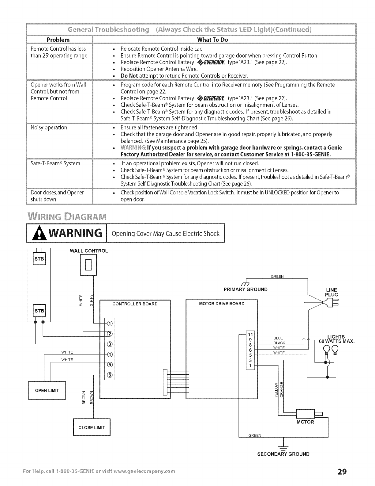
WARNING Opening Cover May Cause Electric Shock I
WALLCONTROL
_b- lal
&
k-
CONTROLLER BOARD
I OPEN LIMIT
- -_
-@
WHITE (_)
WHITE
@
i
i
i
I '
1
1
1
i
I CLOSE LIMIT
PRIMARYGROUND
MOTOR DRIVE BOARD
----111t
19k
13f
GREEN
BLUE
BLACK
WHITE
WHITE
_T LINE
_AX.
GREEN
_L
SECONDARYGROUND

" HE GssH/E C'OM NY LM ['psD
Wl_at is Cove_®d
Any defect in material and workmanship from personal, normal
household use in accordance with the Owner's Manual.
Fo__'How Lo_g
H8000D Series -- Lifetime* on motor, on parts and service.
ISD990 Series -- Lifetime* on motor, 5 years* on parts.
ISD990-2 Series -- Lifetime* on motor and all parts.
ISD995 Series -- Lifetime* on motor and all parts.
ISD995-2WKM Series -- Lifetime* on motor and all parts.
ISD1000 Series -- Lifetime* on motor, all parts and service.
CMD9900 Series -- Lifetime* on motor, S years* on parts.
PRO99 Series -- Lifetime* on motor and all parts.
* for as long as you own your home.This warranty is non-transferable.
W_'_o Get b .......
Thiswarrantyapplies only to the consumer who originally purchased
the product.
Cieog_'a,,.# _:>BR::,,.Scopes
This warranty applies only to Genie products purchased in the United
States and Canada.
If your Genie product is defective, we will send replacement parts or, at
our option, a replacement unit at no charge to you, excluding shipping,
handling and labor costs. If we send replacement parts for your Genie
product, we may use new or reconditioned parts. If we choose to send
a replacement unit, we may use a new or reconditioned one of the
same or similar design.
IMPLIED WARRANTIES, INCLUDING THOSE OF FITNESS FOR A
PARTICULAR PURPOSE AND MERCHANTABILITY (AN UNWRITTEN
WARRANTY THATTHE PRODUCT IS FIT FOR ORDINARY USE) ARE
LIMITED TO ONE YEAR FROM DATE OF PURCHASE. GENIE WILL NOT PAY
FOR: LOSS OF USE OF YOUR GENIE PRODUCT OR PROPERTY DAMAGE
CAUSED BY YOUR GENIE PRODUCT OR ITS FAILURE TO WORK; ANY
SPECIAL INCIDENTAL OR CONSEQUENTIAL DAMAGES; ANY DAMAGES
RESULTING FROM MISUSE OR MODIFICATION OF YOUR GENIE PRODUCT.
Some states and provinces do not allow limitations on how long an
implied warranty lasts or the exclusion of incidental or consequential
damages, so the above exclusions and limitations may not apply.
This warranty is the only one we wil give on your Genie product, and
it sets forth all our responsibilities regarding your Genie product.
There are no other expressed warranties.
State and Province Rights: This warranty gives you specific legal rights,
and you may also have other rights that vary from state to state and
province to province.
How to Get Wa_'_'a_ty ......
....@ , ¢;:@_.
To get warranty service for your Genie product, you must
provide proof of date, and place of purchase of the product.
], ©o- t,,-Vou_self ge_'vk;es
Call Genie Customer Service toll free at 1-800-354-3643, or visit
our website at www.geniecompany.com.Trained Genie
representatives will assist in diagnosing the problem and will
arrange to supply you with the required parts for do-it-yourself
repairs.Trained service representatives are available Monday -
Friday, 8:00 AM - 11:00 PM, and on Saturday, 11:00 AM - 8:00 PM
Eastern Time (subject to holidays).
You can obtain the name of a Genie Factory Authorized Dealer
by calling the Genie Dealer Locator Service at 1-800-654-3643.
If an Authorized dealer provides warranty service, Genie will not
reimburse you or otherwise be responsible for any labor
charges. Your choice of one of the above described service
options is your remedy under this warranty.
. Batteries (which are considered replacement parts)
, Installation
, Commercial use
, Defects resulting from accidents
, Damage while in transit to our service location or damage
from alterations
Misuse or Abuse
Lack of proper maintenance
Unauthorized repairs or modifications of the product
Affixing of any attachment not provided with the product
Programming of Remote Control Devices
Programming of Keypads
Safe-T-Beam ® adjustment/cleaning
Staples through wiring
Pinched or broken wires
Carriage disengaged
Force Control adjustments
Door out of balance
Broken springs or cables
Power outages
Use of extension cords
Missing or damaged parts on discounted, clearanced, final
sale or taped cartons
, Phantom operations
, Fire
, Flood
, Acts of God
, Failure to follow the Owner's Manual
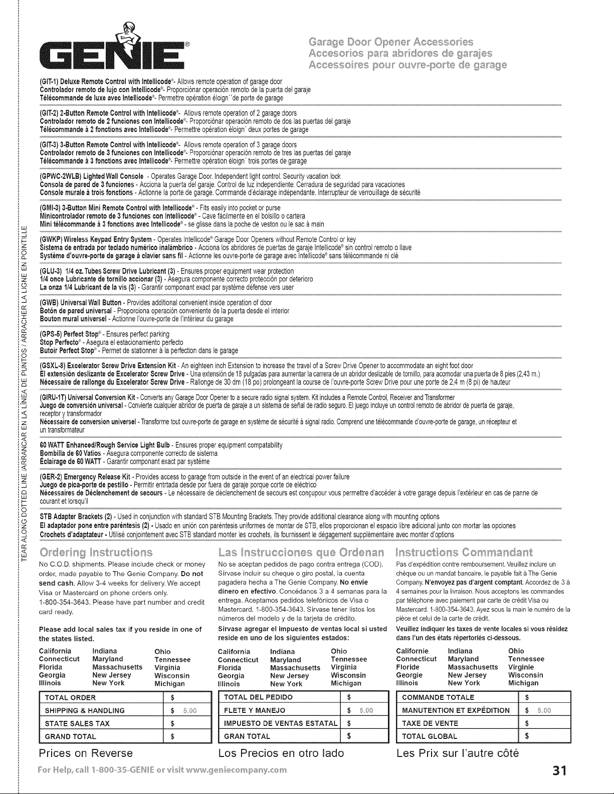
Aco@so os pss sI'x <1o®s de as ;,0,_ss_,,_,_,,,..,
Asc@sso ®s pou_ our ®-pc t@ d@gssg@
(GIT-1)DeluxeRemoteControlwithIntelliaode°- Allowsremoteoperationof garagedoor
Controladorremotode lujo con Intellicode®-ProporciCnaroperacJCnremotodelapuertadelgaraje
Telecommandede luxeavecIntellicode°- Permettreop@atJoneloign"deportede garage
(GIT-2)2-ButtonRemoteControlwith Intellicode®-Allowsremoteoperationof2 garagedoors
Controladorremotede 2 funcionescon Intellioode_-'-ProporciCnaroperaciCnremotode doslaspuertasdeigaraje
Telecommande& 2 fonctJonsaveoIntellJcode®-Permettreop@ationeJoign'deuxportesde garage
(GIT-3)3-ButtonRemoteControlwith Intellicode®-Allowsremoteoperationof3 garagedoors
Controladorremotede 3 funcionescon Intellioode_-'-ProporciCnaroperaciCnremotode treslaspuertasdelgaraje
Telecommande& 3 fonctJonsavecIntellJcode®-Permettreop@ationeloign'troisportesdegarage
(GPWC-2WLB)LightedWallConsole - OperatesGarageDoor.IndependentlightcontrolSecurityvacationlock
Consoladeparedde 3 funcJones- Accionalapuertadelgaraje.Controlde tuzindependiente.Cerraduradeseguridadparavacaciones
Consolemurale&troisfonctions - Actionneia portede garage•Commanded'@lairageind@endante,tnterrupteurdeverrouilagedes@urite
®
(GMI4) 3.ButtonMini RemoteOontrotwith Intellicode - Fitseasilyintopocketor purse
MJnJoontroladorremotede 3 funcionescon Intellicode®- Cavefaotmenteen elbotsiloo cartera
Miniteleoommandea 3 fonctionsaveoIntellicode®-seglissedanslapoohede vestonoule saca main
_- (6WKP)WirelessKeypadEntrySystem-OperatesIntelicode®GarageDoorOpenerswithoutRemoteControlorkey
z $istemade entradaperteoladonumericoJnalambrico- Accionalos abridoresde puertasdegarajeIntetJcode_sincontrolremotoo lave
Bystemed'ouvre-porfede garage&claviersans fil- Actionneies ouvre-portede garageavectntelicode®sanstel@ommandenicie
z
w (6LU-3) 1/4oz,TubesScrewDriveLubricant(3)- Ensuresproperequipmentwearprotection
1/4onceLubricantede tornJlloacoionar(3)- AseguracomponentecorrectoprotecciCnpordeterioro
co Laonza1!4Lubricantde la vJs(3)- GarantJrcomponantexactparsystemedefenseversuser
z
(GWB)UniversalWallButton- Providesadditionalconvenientinsideoperationof door
BotChde pareduniversal- ProporcionaoperacJCnconvenientedela puertadesdeelinterior
Boutonmuraluniversel-Actionnei'ouvre-portede Ilnt@ieurdu garage
<
(6P8-5)Perfect8top®-Ensuresperfectparking
®
_< StopPerfecto_- Asegurael estacionamientoperfecto
co ButoirPerfect8tol? - Permetde statJonnera ta perfectiondansIegarage
O
p-
(GSXL°8)ExceleratorScrewDriveExtensionKit- AneighteeninchExtensionto increasethetravelofa ScrewDriveOpenerto accommodateaneightfootdoor
ElextensiondeslJzantede Excelerator8crewDrive- UnaextensiCnde18pulgadasparaaumentarlacarreradeunabridordestzabledetomito,paraacomodarunapuertade8 pies(2,43m.)
NecessaJrede rallongedu I-:xceleratorScrewDrive- Ratongede 30dm(18 pc)proIongeantta coursede I'ouvre-porteScrewDrivepouruneportede 2,4m (8 pi)dehauteur
<
(GIRU.1T)UniversalConversionKit- ConvertsanyGarageDoorOpenertoa secureradiosignalsystem.Kitincludesa RemoteControl,ReceiverandTransformer
='z JuegcdeconversiCnuniversal-Conviertecuatquierabridordepuertadegarajea unsistemadeseBalderadioseguro.Eljuegoincluyeuncontrolremotodeabridordepuertadegaraje,
receptorytransformador
z Necessairedeconversionuniversel- Transformetoutouvre-portede garageensystemedes@uritea signalradio.Comprendunetetecommanded'ouvre-portedegarage,unr@epteuret
'" untransformateur
n,,"
<
60WATTEnhanced/RoughServiceLight Bulb- Ensuresproperequipmentcompatabilty
,Bombillade 60Vatios- Aseguracomponentecorrectodesistema
Eclairagede 60WATT-Garantircomponantexactparsysteme
(6ER-2)EmergencyReleaseKit- Providesaccessto garagefromoutsideintheeventof anelectricalpowerfailure
z Juego depica-portede pestillo- Permitirentrtadadesdeporfuerade garajeporquecortede el@trico
NecessaJresde Deolenchementde secours- Len@essairede d@bnchementdesecoursestcon£upourvouspermettred'accedera votregaragedepuisI'ext@ieurencasde pannede
_- courantet torsqull
F--
O
8TB AdapterBrackets(2)- Usedin conjunctionwithstandardSTBMountingBrackets.Theyprovideadditionalclearancealongwithmountingoptions
Eladaptadorponeentre parentesis(2)- Usadoenuni6nconpar@testsuniformesde montardeSTB,elos proporcionanel espaciolbre adicionaljuntoconmortarlasopciones
o, Crochetsd'adaptateur- UtilseconjointementavecSTBstandardmonterles crochets,is fournissentiedegagementsupplementaireavecmonterd'options
<
n,,"
uJ
I--
No C.O.D. shipments. Please include check or money
order, made payable to The Genie Company•Do not
send cash. Allow 3-4 weeks for delivery.We accept
Visa or Mastercard on phone orders only.
1-800-354-3643•Please have part number and credit
card ready,
Please add local sales tax if you reside in one of
the states listed,
California Indiana California indiana
Connecticut Maryland Connecticut Maryland
Florida Massachusetts Florida Massachusetts
Georgia New Jersey Georgia New Jersey
Illinois New York Iinois New York
TOTAL ORDER
SHIPPING & HANDLING
STATE SALES TAX
GRAND TOTAL
Prices on Reverse
Ohio
Tennessee
Virginia
Wisconsin
Michigan
$
$ ::£oo
$
$
No se aoeptanpedidosde page oontra entrega (COD).
Sirvase incluir su cheque o gird postal, ta cuenta
pagadera hecha a The Genie Company.No envie
dinero en efectivo. Concedanos 3 a 4 semanas parala
entrega.Aceptames pedidos telef6nicosde Visa o
Mastercard. 1-800-354-3643.Sirvasetener listos tos
nL_merosdel modeloy de la tarjetade cr_dito.
Sirvase agregar el impuesto de ventas local si usted
reside en uno de los siguientes estados:
Ohio
Tennessee
Virginia
Wisconsin
Michigan
TOTAL DEL PEDIDO $
FLETE Y MANEJO $ 500
IMPUESTO DE VENTAS ESTATAL $
GRAM TOTAL $
Los Precios en otro lado
/_st_'uctio_,;s Comma_sdast
Pas d'exp_dition contre remboursement. Veuilez indure un
ch£queou un mandatbancaire,lepayablefait£ The Genie
Company.N'envoyezpasd'argentcomptant.Accordezde 3
4 semainespourlalivraison.Nousacceptonsles commandes
partel@honeavecpaiementpar cartede creditVisaou
Mastercard.1-800-354-3643.Ayezsousla mainlenum@ode la
pieceet celuide lacartede credit.
VeuJlezindiquer les taxes devente locales si vous residez
dartsFundes etatsrepertoriesci-dessous.
Californie Indiana Ohio
Connecticut Maryland Tennessee
Floride Massachusetts Virginie
GeorgJe New Jersey Wisconsin
Illinois New York Michigan
COMMANDETOTALE $
MANUTENTION ETEXPEDITION $ 5.00
TAXE DE VENTE $
TOTAL GLOBAL $
Les Prix sur I'autre c6te
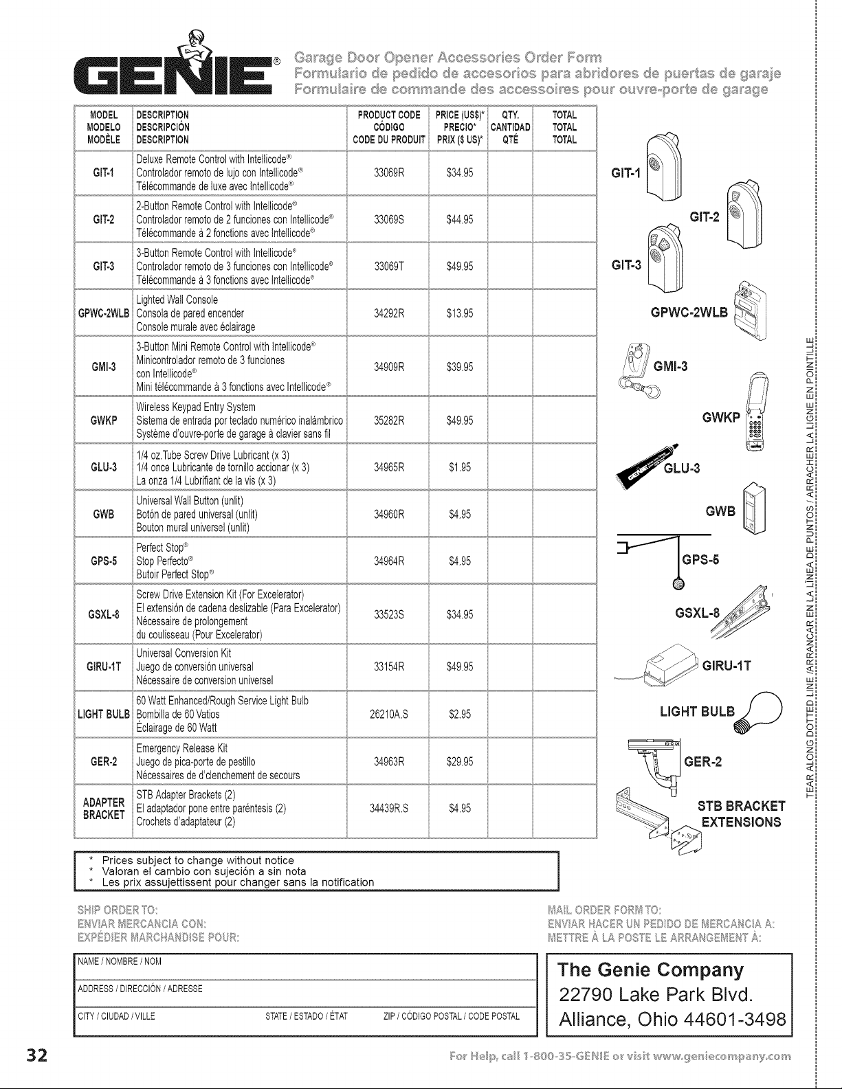
MODEL
MODELO
MODELE
GIT-I
Gff-2
GIT-3
GPWC-2WLB
GMI-3
GWKP
GLU-3
GWB
GPS-5
GSXL-8
GIRU-IT
LIGHTBULB
GER-2
® Garbage Dee_ Opene Aocesso es Odes l';_em _
1"o_ u_a e pedide _,.¢..,_e e,s pa_8 _J"_ do ._:_de..........pue tas d__,,9a_,de_"_*_
DESCRIPTION
DESCRtPCt6N
i
DESCRIPTION
i
DeluxeRemoteControlwithIntelicode®
ControladorremotodelujoconIntelicode®
Tel6commandedeluxeavecIntellcode®
2-ButtonRemoteControlwithtntellcode®
Controladorremotode2fundonesconIntelicode®
Tel@ommande£ 2fonclonsavecIntellcode®
3-ButtonRemoteControlwithtntellcode®
Controladorremotode3fundonesconIntellicode®
Tel@ommandea 3fonclonsavecIntellcode®
LightedWallConsole
Consoladeparedencender
Consolemuraleavec@lairage
3-ButtonMiniRemoteControlwithtntellcode®
Minicontroladorremotode3 funciones
con Intelicode®
Mini tel@ommande£ 3fonctionsavecIntellicode®
WirelessKeypadEntrySystem
Sistemadeentradapottecladonumericoinal£mbrico
Systemed'ouvre-portedegarage£claviersansfil
1/4oz.TubeScrewDriveLubricant(x3)
1/4onceLubricantedetornilloaccionar(x3)
La onza1/4Lubrifiantdelavis(x3)
UniversalWallButton(unlit)
Bot6ndepareduniversal(unlit)
Boutonmuraluniversel(unlit)
PerfectStop®
StopPerfecto®
ScrewDriveExtensionKit(ForExcelerator)
Elextensi6ndecadenadeslizabie(ParaExcelerator)
N@essairedeprolongement
du coulisseau(PourExcelerator)
UniversalConversionKit
Juegodeconversi6nuniversal
N@essairedeconversionuniversel
60WattEnhanced/RoughServiceLightBulb
Bombillade60Vatos
Eclairagede60Watt
EmergencyReleaseKit
Juegodepica-portedepestillo
N@essairesded'clenchementdesecours
PRODUCTCODE
CODIGO
CODEDUPRODUIT
33069R
33069S
33069T
34292R
34909R
35282R
PREClO*
PRIX($ US)*
PRICE(US$)*i QTY.
iCANTIDAD
QTE
$34.95
TOTAL
TOTAL
TOTAL
$44.95
$49.95
$13.95
$39.95
34965R
$49.95
$1.95
34960R $4.95
34964R $4.95
$34.95
$49.95
33523S
33154R
26210A.S
6 i
$2.95
$29.9534963R
ADAPTER STBAdapterBrackets(2)
BRACKET Eladaptadorponeentrepar@tesis(2) 34439R.S $4.95
Crochetsd'adaptateur(2)
GIT-1
GITo2
GIT-3
GPWC-2WLB
GWKP
GWB
GPS-5
GSXLM'
GIRU-1T
LIGHT BULB
GER=2
STB BRACKET
EXTENSIONS
i * Prices subject to change without notice
• Valoran el cambJo con sujeci6n a sin nota
• Les prix assujettissent pour changer sans la notification
t'% _) sy"_, _ _%
M,_L ,,Ru R
_/!E f sc _ .A POSY' .._ ,,,
w:
F--'
zl
oi
zl
wl
wl
z:
©I
<i
-41
rr'l
Wl
II
<i
oi
zl
0-i
w:
,_zl
<I
-J I
zl
wl
ii
rr':
Sl
wl
zl
O:
n:
sl
<I
NAME/NOMBRE/ NOM
ADDRESS/ DIRECCION/ ADRESSE
CITY/ CIUDAD/VILLE STATE/ ESTADO/ ETAT ZIP/ CODIGOPOSTAL/ CODEPOSTAL
The Genie Company
22790 Lake Park Blvd.
Alliance, Ohio 44601=3498