
Loading ...
Loading ...
Loading ...
4
ENGLISH
Dwg Name: VDV500-820-1390301ART
Dwg No: 1390301 Rev: G
Pkg Dwg Ref: 1790 ECO No: 041011
Finish Coat Requirements: N/A
WARNINGS
To ensure safe operations and service of the instruments, follow these instructions. Failure to observe these
warnings can result in re, electric shock, severe injury or death.
•
The Toner-Pro and Probe-Pro are designed for use on extra-low voltage cabling systems (less than 60
volts) for testing when NOT energized.
•
The maximum voltage across ABN Test Clips of the Toner-Pro is 60 volts in Test mode, and 20 volts in
Continuity mode. Connecting the Probe-Pro to live mains AC power may damage it and pose a safety hazard
for the user.
•
DO NOT use instruments if they are wet, as it could pose a shock hazard.
•
DO NOT use instruments if they are damaged in any way.
•
Turn off instruments and disconnect all ABN Test Clips before attempting to replace batteries.
•
The battery door must be in place and secure before you operate the instrument.
•
DO NOT open the case, other than the battery compartment.
OPERATING INSTRUCTIONS
READ ALL INSTRUCTIONS BEFORE OPERATING AND RETAIN INSTRUCTIONS FOR FUTURE REFERENCE
CONTINUITY TEST
The Toner-Pro transmits frequencies on non-energized wires only. When the Toner-Pro is turned on, a continuity
test will be performed to determine if the 2 wires to be traced are in close proximity to each other, without a
conductive path between them. The "CONT" Indicator
T4
wIll illuminate green to indicate pass. Attach the
red and black ABN Test Clips
T14
to the wires to be tested. If the resistance of the circuit is less than 10kΩ, the
"CONT" Indicator
T4
will illuminate red, indicating a short, and no toning can occur. If the ‘CONT’ Indicator is
illuminated green, a tone can be generated and you may proceed.
SELECTING TONE FREQUENCY
The Toner-Pro defaults to the 800Hz frequency setting when powered on. Use the Tone Mode Up
T8
and Tone
Mode Down
T7
selector buttons to change the frequency. The Tone Frequency Indicators
T6
will display the
frequency being transmitted. If an alternating tone is selected, the two respective Tone Frequency Indicators
T6
will blink.
Tones will cycle through the available frequencies in a continuous loop when a selector button is pressed
repeatedly.
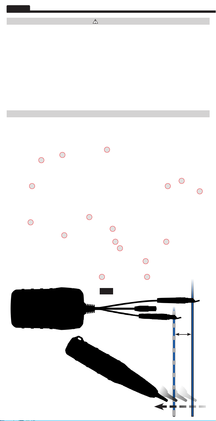
TRACING PAIRED WIRES (FIG. 1)
1. Connect the Toner-Pro’s red ABN Test Clip
T14
to one of the wires of the pair to be traced. Connect the black ABN
Test Clip
T14
to the other wire to be traced.
2. Turn Toner-Pro on by pressing the Power On/Off button
T9
.
3. Check the “CONT” Indicator
T4
. If illuminated green, you may proceed.
4. Select the preferred tone setting using the
Tone Mode Up
T8
and/or
Tone Mode Down
T7
selector buttons.
5. Turn the Probe-Pro on by pressing the Power On/Off button
P5
.
6. At the far end of the cable, spread the wires apart at least 2" (51 mm), if possible.
7. Use the Probe-Pro to scan the cable’s wire pairs. Move the Probe-Pro's tip
P1
slowly across the wires (FIG. 1).
The Probe-Pro’s volume will increase as it approaches the toned pair. When the Probe-Pro’s volume is high over
the first wire, low in the middle (between) the two wires, and high over the second wire, you have located the pair
of wires you are tracing. Use the
Volume Increase
P6
and
Volume Decrease
P7
buttons to adjust the volume.
2"
(51 mm)
FIG. 1
VDV500-820-1390301ART - Pro Tone and Probe Kit.indd 4VDV500-820-1390301ART - Pro Tone and Probe Kit.indd 4 7/30/21 10:26 AM7/30/21 10:26 AM
Loading ...
Loading ...
Loading ...