Loading ...
Loading ...
MODELS
L400KL • L500KL
Page 3
;;yy
;;;yyy
21½"
9
1
/
2" to
10
1
/
2"
;;yy
;;;yyy
21½"
10
3
/
4
" to
11
3
/
4
"
MOUNTING OPTIONS
WIRING OPTIONS
DUCTING OPTIONS
;y
;;;yyy
21½"
1
1
/
8
"
MAX.
Mounting brackets in
factory-shipped position.
(Outlet parallel to joists.)
(
New construction)
;;;yyy
;;;yyy
12¼"
¼-20 hex nuts secure mounting brackets to housing. Loosen and
re-tighten or remove and replace nuts as necessary for desired
mounting bracket position.
Mounting brackets mounted
to outlet sides of housing.
(Outlet perpendicular to joists.)
(
New construction)
Mounting brackets flipped
over and mounted to top of
sides of housing.
(Outlet parallel to joists.)
(
New or existing construction)
1
1
/
2
"
to
2
1
/
2
"
;y
;;;yyy
21½"
Mounting brackets flipped
over to give approx. 1”
more clearance.
(Outlet parallel to joists.)
(
New construction)
Mounting brackets mounted
to top of sides of housing.
(Outlet parallel to joists.)
(
New or existing construction)
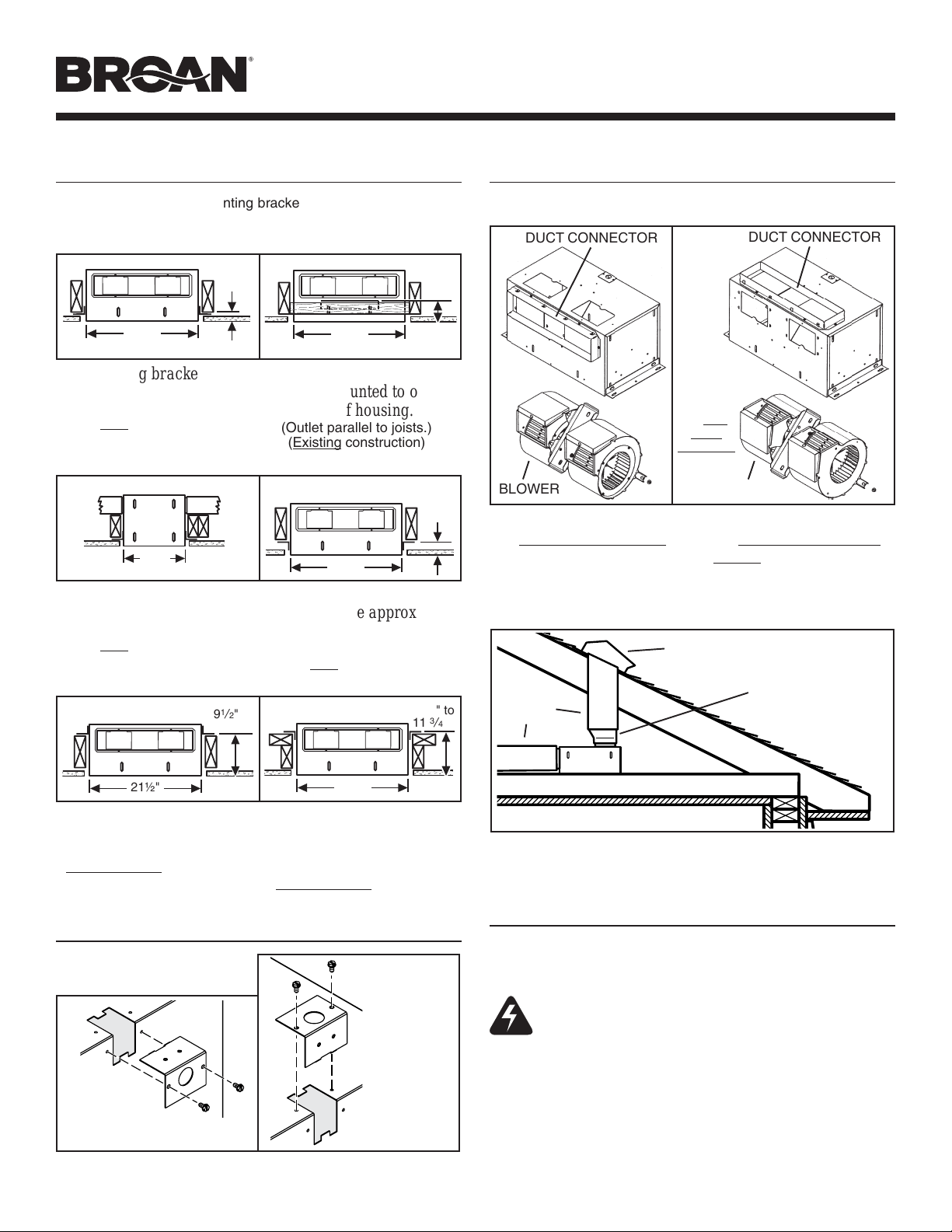
BLOWER DISCHARGE POSITIONS
WIRING PLATE
POSITION
Wiring plate mounts to side or top of housing.
HORIZONTAL POWER
CABLE CONNECTION
VERTICAL
POWER
CABLE
CONNECTION
Blower and duct connector
in
right angle discharge
position.
Blower and duct connector
in
straight-through dis-
charge position. (Factory
shipped)
BLOWER
Change
blower
& duct
connector
positions
for right
angle
discharge.
DUCTING
(Right angle blower discharge)
Typical ductwork connection to a ventilator converted to
right angle discharge.
ROOF CAP
10”
ROUND
DUCT
WARNING: To reduce the risk of electric shock,
disconnect from power supply before servicing.
To clean blower assembly: Remove access panel, unplug blower
from housing, remove blower mounting nuts, and carefully remove
blower from housing. Use appropriate vacuum attachment or a soft
cloth and mild soap or detergent to clean blower discharge area
and wheel. DO NOT ALLOW WATER TO ENTER MOTOR. Make
sure blower assembly is completely dry before reinstalling.
Motor is permanently lubricated. Do not oil or disassemble motor.
USE AND CARE
Ventilator is designed for continuous operation. If desired, it may
be controlled using an on/off switch or a solid-state, variable speed
control. Follow wiring instructions packed with control, and adhere
to all local and state codes, and the National Electrical Code.
4½” X 18½”
TO 10” ROUND
TRANSITION
;;yy
;;;yyy
21½"
1½"
to
2½"
;;;
;;;
@@@
@@@
;;;
;;;
@@@
@@@
;;;
;;;
@@@
@@@
;;;
;;;
@@@
@@@
;;;
;;;
@@@
@@@
;;;
;;;
@@@
@@@
;;;
;;;
yyy
yyy
;;@@
;;@@
;;@@
;;@@
;;@@
;;@@
;;yy
Mounting brackets flipped
over and mounted to outlet
sides of housing.
(Outlet parallel to joists.)
(
Existing construction)
DUCT CONNECTOR
BLOWER
DUCT CONNECTOR
Loading ...
Loading ...
Loading ...