Loading ...
Loading ...
Loading ...
RGBlink vue PTZ camera User Manual
8
Chapter 2 Install Your Product
2.1 Camera Interface Explanation
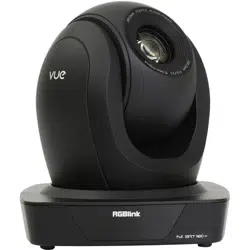
Figure 2.1 Camera Interface
Interface explanation
1
、
Camera Lens
6
、
Network Interface
11、3G-SDI Interface
2
、
Camera Base
7
、
RS232 Control Interface (input )
12、HDMI Interface
3
、
Bottom Dial Switch
4
、
Tripod Screw Hole
8、 RS232 Control Interface (output)
9、 RS485 Input (left +,right-)
13、USB Interface
5 、 DC12V Input Power Supply
Socket
10、Audio Input Interface
2.1.1 External Interface
External interface: LAN, RS232 Input /Output, RS485 Input, Audio Input, 3G-SDI Output, HDMI Output, USB
Interface, DC12V Power Interface.
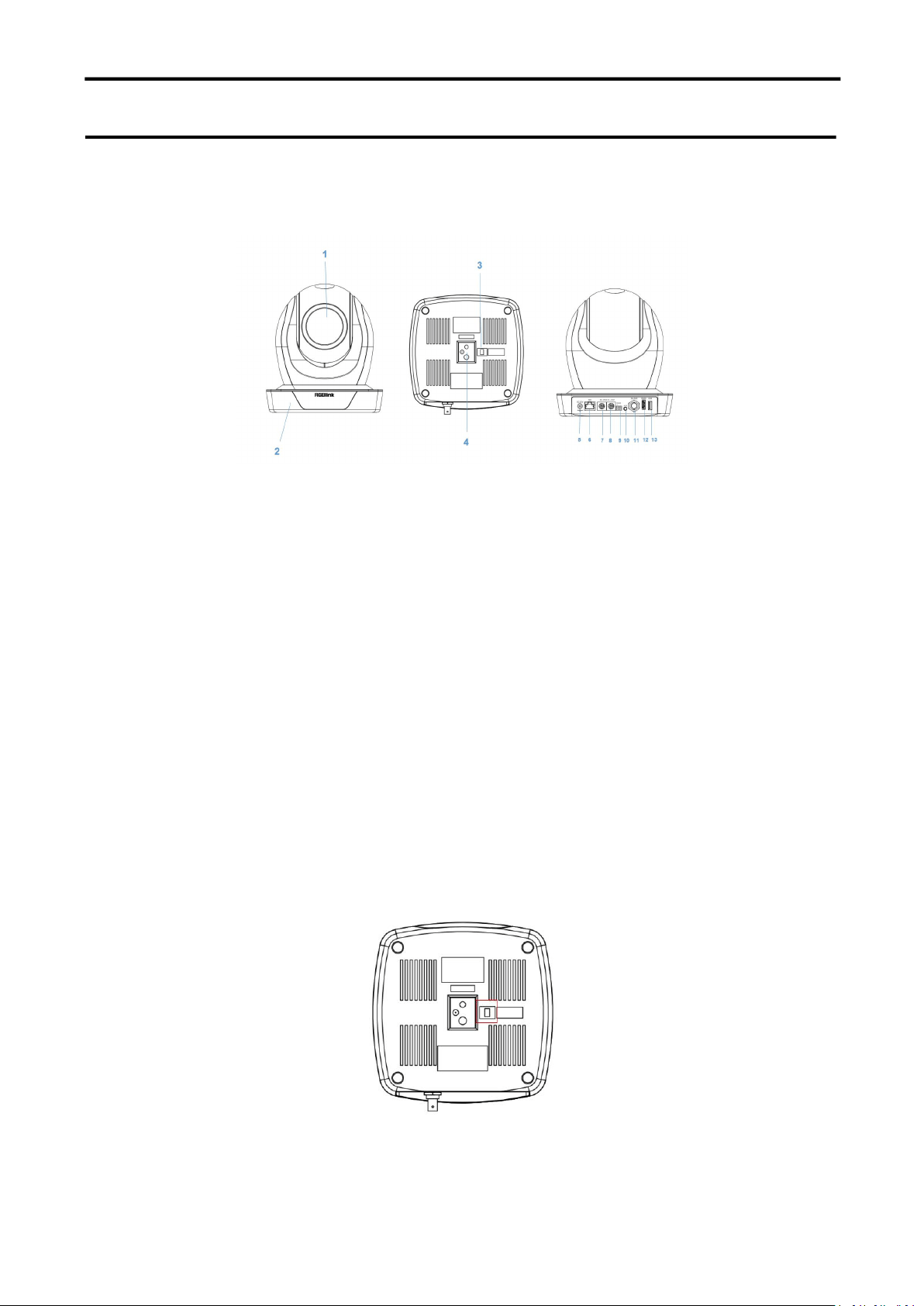
2.1.2 Bottom Dial Switch
Broadcast PTZ Camera Camera Bottom Dial Switch diagram shown in Figure 2.2
Figure 2.2 Bottom Dial Switch Diagram
Loading ...
Loading ...
Loading ...