Loading ...
Loading ...
Loading ...
9
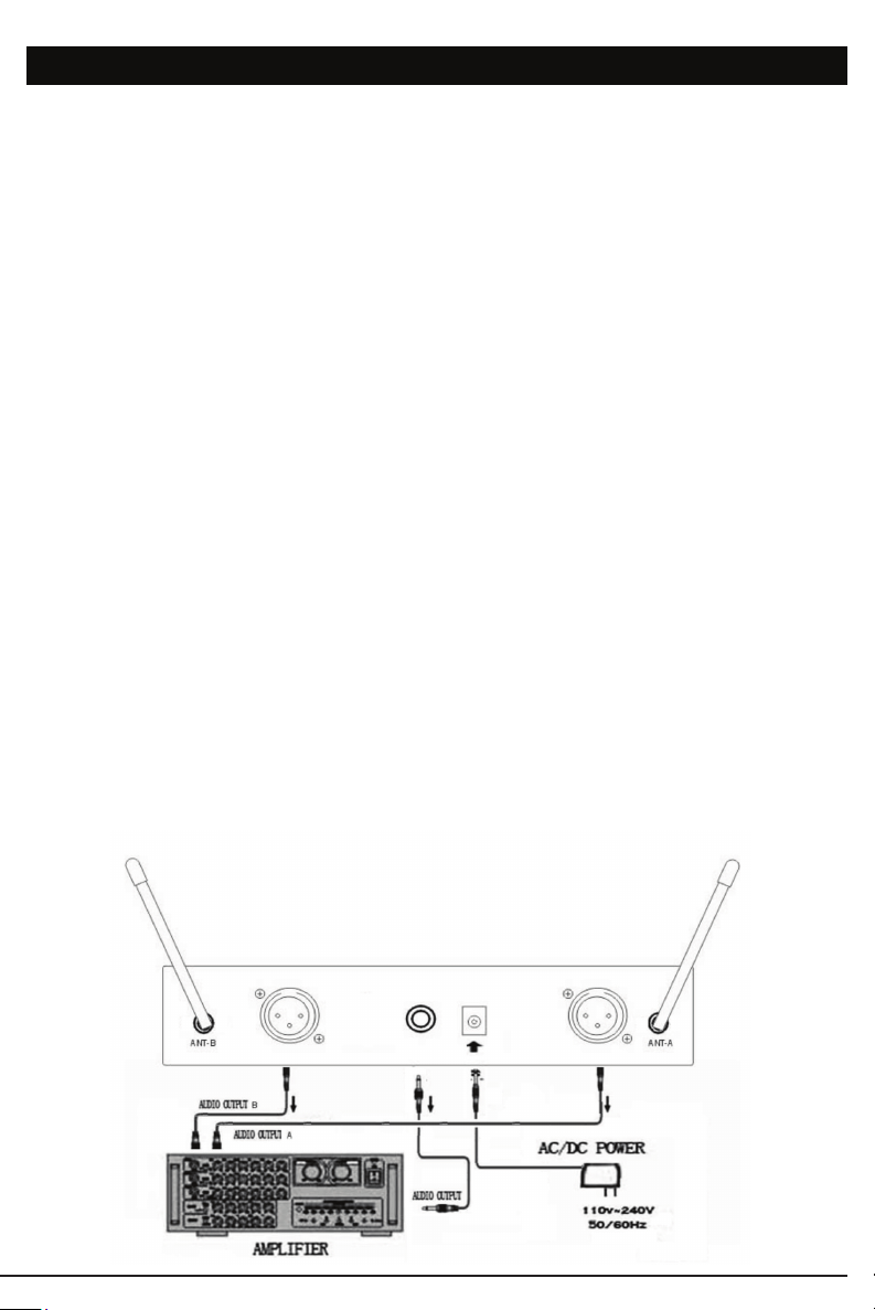
DW-11 and DW-22 Receiver Back
( showing the connection )
DIGITAL LT/HM
TM
BODYPACK TRANSMITTER
4. The DIGITAL LT™ is provided with a 3.5 mm LOCKING JACK (18) for connecting
the audio input selected. Connect either HEADWORN MIC or LAVALIER MIC CORD
(23) as desired, according to the model selected.
[ Note: Use only the input selected or the audio will not be optimal–a muddy or distorted
sound may result. To secure the connection, turn the slip ring on the plug clockwise to
thread it on the jack. To unplug, reverse the process.]
Slip the transmitter into a pocket or BELT CLIP (20) on to your clothes.
5. Microphone Use (with either a Lavalier or Headworn microphone)
Secure the connection from the LAVALIER or HEADWORN MIC CORD(23) by turning
the slip ring on the plug into the transmitter clockwise to thread it onto the jack. To
unplug, reverse the process. To use the Lavalier Mic, attach it at chest level. Do not
place it too close to the mouth–a distance of about six inches usually works best. To
use the head worn Mic, place it on the head and adjust the boom so that the Mic is
about one inch to the side of the front of the mouth.
[ Note: Observe care in selecting P.A. volume, transmitter location and speaker placement
so that acoustic feedback (howling and screeching) is avoided. Also note the pickup pattern
characteristics of the microphone selected: Omnidirectional mics pick up sound equally
from all directions and are prone to feedback if not used carefully. Unidirectional Mics are
more resistant to feedback, but pick up sound sources best that are directly in front of the
Mic. Mics that are farther from the sound source, such as lavaliers, require more acoustic
gain and thus are also more prone to feedback than close-source Mics such as handheld
or headworn models that are used close to the mouth. ]
6. Sample Connections: Connect ¼” output for A and B Channels to Mixer inputs.
Use the volume to set for optimum output. VOLUME CONTROL (6) is for LINE/MIX
1/4” jack (8) AUDIO OUTPUT only. For separate control, use XLR outputs to each
Mixer input, control the level from the Mixer. Power adapter connection as shown in
the picture below.
Loading ...
Loading ...
Loading ...