NEED HELP? CONTACT US!
Have product questions? Need technical support?
Please feel free to contact us:
This is the original instruction, please read all manual instructions carefully before operating.
VEVOR reserves clear interpretation of our user manual. The appearance of the product shall
be subject to the product you received. Please forgive us that we won't inform you again if
there is any technology or software updates on our product.
RV-30A
030201
TOUGH TOOLS, HALF PRICE
Installation Instructions
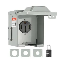
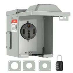
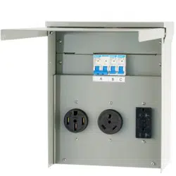
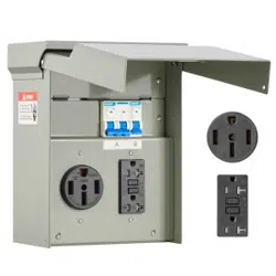
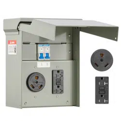
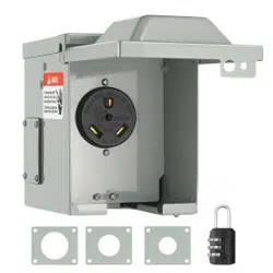
Power Outlet Box
Sku#: DGNRV30ATT30RA943V0
Model: RV-30A
Desc: AC 30A 125/250V
NEMA: XD-010(TT-30R)
WARNINGI: ELECTRICAL SHOCK AND FIRE
HAZARD!
The outlet is not to be connected to power prlor to
installation. Fallure to comply with thisinstruction could
result in an electrical failure, fire and electrocution.
IMPORTANT: Installation of this power outlet box and
related wiring must be done by aqualified electrician in
compliance with all applicable electrical codes, When
being used ttpower a structure, this outlet must be used
in conjunctlon with a transfer switch, Not forindoor use,
When using an engine driven generator, locate away
from doors and windows toavoid the build-up of carbon
monoxide from the engine exhaust in enclosed areas.
Installing the Power Outlet Box:
Mount the power outlet box on the outside of the
building in a convenient location, using thethree holes
provided in the back of the cabinet, Using copper wire
only and approved wiringmethods, run the wiring
through one of the knockouts in the cabinet to a
junction boxlocated near the transfer switch, If using
conduit, pull at least four colors.
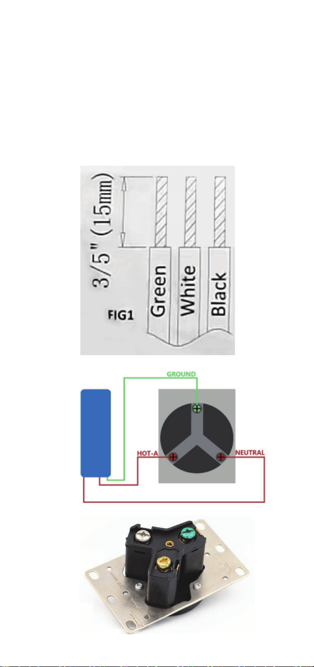
WireGauge: 6AWG~10AWG. Strip the wire insulation
3/5"(15mm,FIG1) (do not tin conductors) and connect
the wires inthe power outlet box as follows. Making
sure there ls no wire insulatlon in any terminal ancthe
outlet terminal screws are tightened to 35 inch-pounds
torque using Electric flat Screwdriver.
Cable Color Scheme:
Black/Red=Load (250 Vlot),the terminals marked
“Black”
White=W-Neutral Conductor connected to “White"mark-
ing terminal”
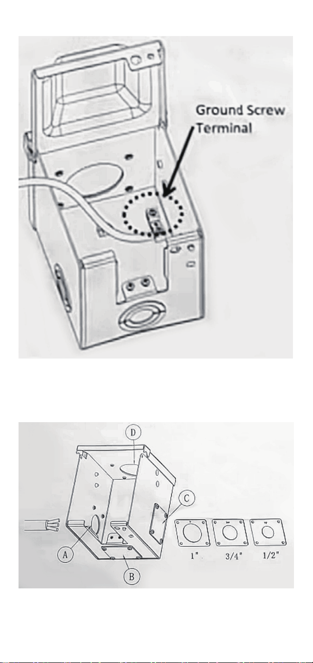
Green=Green power inlet wire to green ground screw
terminal on inside of cabinet. If required, green wire to
green ground screw terminal on inside of cabinet.(-
FIG2)

NEED HELP? CONTACT US!
Have product questions? Need technical support?
Please feel free to contact us:
This is the original instruction, please read all manual instructions carefully before operating.
VEVOR reserves clear interpretation of our user manual. The appearance of the product shall
be subject to the product you received. Please forgive us that we won't inform you again if
there is any technology or software updates on our product.
RV-30A
030201
TOUGH TOOLS, HALF PRICE
Installation Instructions
Power Outlet Box
Sku#: DGNRV30ATT30RA943V0
Model: RV-30A
Desc: AC 30A 125/250V
NEMA: XD-010(TT-30R)
WARNINGI: ELECTRICAL SHOCK AND FIRE
HAZARD!
The outlet is not to be connected to power prlor to
installation. Fallure to comply with thisinstruction could
result in an electrical failure, fire and electrocution.
IMPORTANT: Installation of this power outlet box and
related wiring must be done by aqualified electrician in
compliance with all applicable electrical codes, When
being used ttpower a structure, this outlet must be used
in conjunctlon with a transfer switch, Not forindoor use,
When using an engine driven generator, locate away
from doors and windows toavoid the build-up of carbon
monoxide from the engine exhaust in enclosed areas.
Installing the Power Outlet Box:
Mount the power outlet box on the outside of the
building in a convenient location, using thethree holes
provided in the back of the cabinet, Using copper wire
only and approved wiringmethods, run the wiring
through one of the knockouts in the cabinet to a
junction boxlocated near the transfer switch, If using
conduit, pull at least four colors.
WireGauge: 6AWG~10AWG. Strip the wire insulation
3/5"(15mm,FIG1) (do not tin conductors) and connect
the wires inthe power outlet box as follows. Making
sure there ls no wire insulatlon in any terminal ancthe
outlet terminal screws are tightened to 35 inch-pounds
torque using Electric flat Screwdriver.
Cable Color Scheme:
Black/Red=Load (250 Vlot),the terminals marked
“Black”
White=W-Neutral Conductor connected to “White"mark-
ing terminal”
Green=Green power inlet wire to green ground screw
terminal on inside of cabinet. If required, green wire to
green ground screw terminal on inside of cabinet.(-
FIG2)
TOUGH TOOLS, HALF PRICE
Technical Support and E-Warranty Certificate
www.vevor.com/support
Power Outlet Box
We continue to be committed to provide you tools with competitive price.
"Save Half", "Half Price" or any other similar expressions used by us only
represents an estimate of savings you might benefit from buying certain tools
with us compared to the major top brands and doses not necessarily mean to
cover all categories of tools offered by us.
You are kindly reminded to verify carefully when you are placing an order with
us if you are actually saving half in comparison with the top major brands.
Technical Support and E-Warranty Certificate
www.vevor.com/support
Enter installation considerations:
Choose one threading hole that suits you the best.
(A,B,C,or D)
Made In China
04