Loading ...
Loading ...
Loading ...
– 13 – – 14 – – 15 – – 16 –
–
17 – – 18 –
– 19 – – 20 –
– 21 – – 22 – – 23 –
Out-of-Beam Indication
The receiver has an out-of-beam (OOB) function. When it is turned on, the LED
grade display indicates that the receiver has moved beyond the vertical laser-reception
range. A sequence of LEDs indicates which direction to move the blade or cutting
edge to pick up the laser beam. If the receiver is above the beam, move the edge down.
If the receiver is below the beam, move the edge up. The sequence stops as soon as a
laser signal is received. Otherwise, the function shuts off after two minutes.
The factory default setting is for the out-of-beam function to be on. The LED display
sequences inward toward on-grade to indicate that the function is on. To turn the
function off, press the two outside buttons (Blade Tilt and Display Brightness) at the
same time. The LED display sequences outward from on-grade to indicate that the
function is off.
Slope Matching
The blade-tilt indicator can be nulled or set to zero for a blade slope other than
level. This function is used for matching an existing slope or setting the blade to a
predetermined slope.
The factory default setting for the blade-tilt indicator is level.
To change the blade-tilt indicator at a slope other than level:
1. Position the blade at the desired slope. Make sure the receiver is properly aligned
with the blade from side to side and front to back.
2. With the receiver on, press and hold the power button and immediately press
and hold both the blade-tilt button and the display-brightness button. Continue
holding all three buttons until a “0” symbol followed by a “Y” symbol briefly
displays. The blade slope is now nulled at the existing slope.
3. To reset the blade-tilt indication back to level, position the blade to level using a
four-foot level or other method. Repeat the above procedure with the blade level.
This procedure may also be used to correct the display when a mast is not aligned
properly to the blade.
Excavating
When an excavator or backhoe is being used, the dipper arm should be vertical or near
vertical and the bucket positioned so that it can easily be put in the same position each
time a grade reading is taken. The bucket can be fully extended or curled as long as
the position is consistent when grade readings are taken. The receiver can be set up in
the trench or out of the trench if the cut elevation can be determined.
In-Trench Setup
7. Mount the receiver on the mast, and adjust the dipper arm so that the receiver is
within the plumb range—LEDs solid. Adjust the plumb-accuracy indication if
desired.
8. Slide the receiver up or down until you get a solid on-grade display.
9. Select the desired deadband and begin excavating.
10. Take grade readings with the bucket in the grade-checking position and the grade-
display LEDs solid.
11. Take a sample reading with the bucket “on-grade” and check to make sure the
elevation is correct.
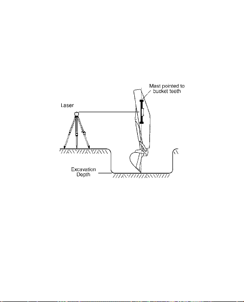
Out of Trench Set-Up
3. Determine the distance from the laser to the bottom of the trench (L). This is the
setup length. The length is the height of the instrument (HI) plus the depth of cut
from the benchmark to the bottom of the trench (C).
4. Mount the mast on the side of the dipper arm.
5. Point the mast at the bucket teeth as illustrated if checking grade with the bucket
fully extended. (If checking grade with the bucket curled or other position, point
the mast to the point of the bucket that makes contact with the ground.)
6. Position the receiver so the setup length (L) is the distance from the point of the
bucket that makes contact with the ground to the offset on-grade symbol on the
back label. (Set up to center on-grade symbol if center on-grade is being used).
7. Turn on the receiver and select offset on-grade and the desired deadband.
8. Adjust the plumb-accuracy indication if desired. (Select center on-grade if set to
center symbol).
9. Begin excavating.
10. Take grade readings with the bucket in the grade-checking position and the grade-
display LEDs solid.
11. Take a sample reading with the bucket “on-grade” and check to make sure the
elevation is correct.
Installation
General
WARNING: Follow all safety precautions as discussed in the machine’s user
guide. Also follow all excavation and safety requirements and practices.
1. Set up the laser in an appropriate location for receiver visibility and efficient
machine operation. For more information about laser setup, please refer to the
laser’s user guide. Turn on the laser.
Note: Operating distances depend on the rotating laser power. The receiver can
pick up the beam from all directions (360°), but it requires a clear line of sight to
the laser.
2. If your laser has selectable rotation speeds, select a high rotation speed. The receiver
can process speeds up to 1200 RPM.
3. To mount the receiver on the mast, turn the top and bottom mounting knobs
counterclockwise until the clamps in back open enough to fit around the mounting
mast. Place the receiver on the mast. Turn the knobs clockwise to tighten the
clamps.
Note: The receiver will mount to round tubing that has a 42 mm to 50 mm
(1.66 in. to 2.00 in.) outside diameter or to 38 mm (1
1
/2 in.) square tubing.
4. To remove the receiver from the mast, loosen the two clamps.
The blade-tilt and plumb indications are measured
inside the receiver. The blade tilt indicates side-to-side
position. Plumb indicates front-to-back position. Masts
and receivers must be properly aligned to the machinery
for accurate indications.
2. Set up the laser in an appropriate location for receiver visibility and efficient
machine operation. Turn on the laser.
3. Turn on the receiver, select center on-grade (grading mode), and select the smallest
deadband.
4. To mount the receiver on the mast, turn the top and bottom mounting knobs
counterclockwise until the clamps in back open enough to fit around the mounting
mast. Place the receiver on the mast.
5. Slide the receiver up or down until on-grade is indicated. Adjusting the height of
the laser may be necessary.
Note: Alternatively, if the height of instrument (laser beam) to finished elevation
length is known, the receiver can be set by measuring this distance from the cutting
edge of the blade to the center on-grade mark on the back of the receiver label.
6. Face the LED grade display toward the machine and turn the mounting knobs
clockwise to tighten the clamps
7. Select the desired deadband and brightness.
Note: The LED grade display indicates which way to move the blade using the
machine’s controls to maintain an on-grade reading.
8. Make a sample pass with the blade “on-grade” and check to make sure the
elevation is correct.
Specifications
Beam Reception Range 360 degrees
Operating Range Over 460 m (1500 ft) radius, laser dependent
Laser RPM Minimum: 105; Maximum: 1200
Vertical Reception 171 mm (6.75 in.)
Accuracy: Fine Standard Wide
Center On-Grade
(Grading)
5 mm
(0.20 in.)
10 mm
(0.40 in.)
20 mm
(0.80 in.)
Offset On-Grade
(Excavation)
12 mm
(0.50 in.)
25 mm
(1.0 in.)
50 mm
(2.0 in.)
Blade-Tilt & Plumb-Swing Accuracy
± 0.5°, ± 1.5°, ± 2.5°
Display Output Bright or Dim
Automatic Control Capability Yes, with CB20, CB25 and CB30 Control Box
Power Options Alkaline – 4 x “C” Cell – Standard
Nickel Metal Hydride – 4 x “C” Cell
Power Cable – 10 –30 V dc
LR50 Battery Life – Alkaline
LR50W Battery Life – Alkaline
(Continuous in beam)
60 hours, Display Dim / 45 Hours, Display Bright
30 hours, Display Dim / 20 Hours, Display Bright
LR50 Battery Life – Ni-MH
LR50W Battery Life – Ni-MH
(Continuous in beam)
45 hours, Display Dim / 30 hours, Display Bright
20 hours, Display Dim / 15 hours, Display Bright
Battery Recharge Time 3 – 4 hours
Automatic Shutoff 75 minutes with no laser beam
Out-of-Beam Indication High and Low, Selectable On or Off
Remote Display Option Yes
Dimensions (LxWxD)
343 mm x 142 mm x 149 mm
(13.50 in. x 5.58 in. x 5.88 in.)
Mounting Pipe
Round Tube (Outside Diameter)
Square Tube
42 mm to 50 mm (1.66 in. to 2.00 in.)
38 mm (1 ½ in.)
Operating Temperature –20 °C to +60 °C (–4 °F to 140 °F)
*Specifications subject to change without notice
Declaration of Conformity
This receiver to which this declaration relates is in conformity with the essential
requirements and other relevant requirements of the Directive 2004/108/EC (EMC),
Directive 2006/95/EC (LVD) and Council Directive 1999/5/EC R&TTE.
Safety: (article 3.1a) BS EN60950-1: 2006/A12:2011
EN 62311:2008
EMC: (article 3.1b) ETSI EN 301 489-1 V1.9.2 (2011-09) in accordance with
the specific requirements of CISPR22 Class A
ETSI EN 301 489-17 V2.1.1 (2009-05)
Spectrum: (article 3.2) ETSI EN 300 328 V1.7.1 (2006-10), EN61000-9-2,
EN61000-9-3, EN61000-9-6, EN61000-9-8
We hereby declare that the equipment specified above conforms to the above
Directive(s).
Trimble Navigation Ltd. August 24, 2012
5475 Kellenburger Road
Dayton, OH 45424-1099 U.S.A.
Warranty
Trimble warrants the receiver to be free of defects in material and workmanship for a
period of two years.
Trimble or its authorized service center will repair or replace, at its option, any
defective part for which notice has been given during the warranty period. If required,
travel and per diem expenses to and from the place where repairs are made will be
charged to the customer at the prevailing rates.
Customers should send the product to the nearest authorized service center for
warranty repairs, freight prepaid. In countries with Trimble subsidiary service centers,
the repaired product will be returned to the customer, freight prepaid.
Any evidence of negligent, abnormal use, accident, or any attempt to repair the
product by other than factory-authorized personnel using Trimble certified or
recommended parts, automatically voids the warranty.
The foregoing states the entire liability of Trimble regarding the purchase and use of its
equipment. Trimble will not be held responsible for any consequential loss or damage
of any kind.
This warranty is in lieu of all other warranties, except as set forth above, including
any implied warranty merchantability of fitness for a particular purpose, are hereby
disclaimed. This warranty is in lieu of all other warranties, expressed or implied.
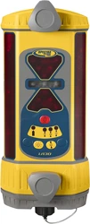
Low-Battery Warning
The receiver has low-battery warning LEDs. During
normal operation with good batteries, the LEDs
are off. When the batteries are low, the LEDs begin
flashing. When the warning occurs, the receiver
continues to operate as normal, but about 90
minutes of battery life remain. When the batteries are too low for normal operation,
the LEDs remain on, the four corner grade-display LEDs flash, and the receiver no
longer receives laser signals. Replace the batteries (or recharge them if you’re using
rechargeable batteries). The warning does not operate when the receiver is connected
to machine power via a power cable.
Grading
1. Position the machine and dig to the desired finished elevation.
2. Position the bucket in the grade-checking position at the finished elevation.
3. Set up the laser in an appropriate location for receiver visibility and efficient
machine operation. Turn on the laser.
4. Mount the mast on the side of the dipper arm.
5. Point the mast at the bucket teeth as illustrated if checking grade with the bucket
fully extended. (If checking grade with the bucket curled or other position, point
the mast to the point of the bucket that makes contact with the ground.)
6. Turn on the receiver, and select the offset on-grade and the smallest deadband.
Sequence to
lower implement
Sequence to
raise implement
Out of Beam Indication ON
Typical excavator
installation
Typical dozer
installation
1. Position the machine so the blade can be set to the desired finished elevation
(typically on a benchmark or hub stake).
Laser
Center
On-grade
Finished Elevation
Benchmark
"Y" symbol "O" symbol
1. Set the laser up in an appropriate location for receiver visibility and efficient
machine operation and turn it on.
2. Place the bucket in the grade-checking position and situate the machine so a
measurement can safely be obtained on the dipper arm. The dipper arm may be
set more horizontal to the ground for convenient measurements if necessary.
Notice to Our European Union Customers
For product recycling instructions and more information,
please go to: www.trimble.com/environment/summary.html
Recycling in Europe
To recycle Trimble WEEE,
call: +31 497 53 2430, and
ask for the ÒWEEE associate,Ó or
mail a request for recycling instructions to:
Trimble Europe BV
c/o Menlo Worldwide Logistics
Meerheide 45
5521 DZ Eersel, NL
Make sure dozer mast is vertically aligned with the blade (both front-to-back and side-
to-side) when the blade is in its normal operating position.
For excavation, the mast typically points towards the bucket teeth. For additional
installation details, see “Slope Matching.”
Plumb axis
rotation
Blade tilt
axis rotation
Trimble
Spectra Precision Division
5475 Kellenburger Road
Dayton, Ohio 45424-1099
U.S.A.
+1-937-245-5600 Phone
www.trimble.com
© 2005-2013, Trimble Navigation Limited. All rights reserved.
Reorder PN 0312-0450 (04/13)
Loading ...
Loading ...
Loading ...