Analog 4-Wire Video Intercom
Quick Start Guide
V1.
1.1

I
Foreword
General
This manual mainly introduces structure, installation, wiring and menu operations of the analog 4-wire
video intercom. Read carefully before using the device, and keep the manual safe for future reference.
Model
VTH1020J, and VTH1020J-T
Safety Instructions
The following categorized signal words with defined meaning might appear in the manual.
Signal Words Meaning
DANGER
Indicates a high potential hazard which, if not avoided, will result in
death or serious injury.
WARNING
Indicates a medium or low potential hazard which, if not avoided,
could result in slight or moderate injury.
CAUTION
Indicates a potential risk which, if not avoided, could result in
property damage, data loss,
reductions in performance, or
unpredictable results.
TIPS
Provides methods to help you solve a problem or save time.
NOTE
Provides additional information as a supplement to the text.
Revision History
Version Revision Content Release Time
V1.1.1 Revised wiring description. November 2022
V1.1.0
A
dded description of the functions of
VTH1020J-T.
Added Factory Reset function.
March 2021
V1.0.0 First release. August 2020
Privacy Protection Notice
As the device user or data controller, you might collect the personal data of others such as their face,
fingerprints, and license plate number. You need to be in compliance with your local privacy protection
laws and regulations to protect the legitimate rights and interests of other people by implementing
measures which include but are not limited: Providing clear and visible identification to inform people
of the existence of the surveillance area and provide required contact information.

II
About the Manual
The manual is for reference only. Slight differences might be found between the manual and the
product.
We are not liable for losses incurred due to operating the product in ways that are not in
compliance with the manual.
The manual will be updated according to the latest laws and regulations of related jurisdictions.
For detailed information, see the paper user’s manual, use our CD-ROM, scan the QR code or visit
our official website. The manual is for reference only. Slight differences might be found between
the electronic version and the paper version.
All designs and software are subject to change without prior written notice. Product updates
might result in some differences appearing between the actual product and the manual. Please
contact customer service for the latest program and supplementary documentation.
There might be errors in the print or deviations in the description of the functions, operations and
technical data. If there is any doubt or dispute, we reserve the right of final explanation.
Upgrade the reader software or try other mainstream reader software if the manual (in PDF
format) cannot be opened.
All trademarks, registered trademarks and company names in the manual are properties of their
respective owners.
Please visit our website, contact the supplier or customer service if any problems occur while
using the device.
If there is any uncertainty or controversy, we reserve the right of final explanation.

III
Important Safeguards and Warnings
This section introduces content covering the proper handling of the device, hazard prevention, and
prevention of property damage. Read carefully before using the device, comply with the guidelines
when using it.
Operation Requirements
●
Check whether the power supply is correct before use.
●
Do not unplug the power cord on the side of the device while the adapter is powered on.
●
Operate the device within the rated range of power input and output.
●
Transport, use and store the device under allowed humidity and temperature conditions.
●
Do not drop or splash liquid onto the device, and make sure that there is no object filled with liquid
on the device to prevent liquid from flowing into it.
●
Do not disassemble the device without professional instruction.
Installation Requirements
●
Do not connect the power adapter to the device while the adapter is powered on.
●
Strictly comply with the local electric safety code and standards. Make sure the ambient voltage is
stable and meets the power supply requirements of the device.
●
Do not connect the device to two or more kinds of power supplies, to avoid damage to the device.
●
Improper use of the battery might result in a fire or explosion.
●
Personnel working at heights must take all necessary measures to ensure personal safety including
wearing a helmet and safety belts.
●
Do not place the device in a place exposed to sunlight or near heat sources.
●
Keep the device away from dampness, dust, and soot.
●
Install the device on a stable surface to prevent it from falling.
●
Install the device in a well-ventilated place, and do not block its ventilation.
●
Use an adapter or cabinet power supply provided by the manufacturer.
●
Use the power cords that are recommended for the region and conform to the rated power
specifications.
●
The power supply must conform to the requirements of ES1 in IEC 62368-1 standard and be no
higher than PS2. Please note that the power supply requirements are subject to the device label.
●
The device is a class I electrical appliance. Make sure that the power supply of the device is
connected to a power socket with protective earthing.

IV
Table of Contents
Foreword ............................................................................................................................................................ I
Important Safeguards and Warnings ............................................................................................................. III
1 Structure ........................................................................................................................................................ 1
Introduction ................................................................................................................................................................................. 1
Features ......................................................................................................................................................................................... 1
Front Panel .................................................................................................................................................................................... 1
Rear Panel ..................................................................................................................................................................................... 3
2 Installation ..................................................................................................................................................... 4
VTH .................................................................................................................................................................................................. 4
VTO .................................................................................................................................................................................................. 4
3 Wiring ............................................................................................................................................................. 6
Preparations ................................................................................................................................................................................. 6
3.1.1 Port Connection Rules ................................................................................................................................................ 6
3.1.2 Cord Specification......................................................................................................................................................... 7
Wiring One VTO and One VTH ............................................................................................................................................... 7
Wiring One VTO and Three VTHs .......................................................................................................................................... 8
Wiring Two VTOs and Three VTHs ........................................................................................................................................ 9
4 Menu Operations ......................................................................................................................................... 10
Snapshots.................................................................................................................................................................................... 10
Time ............................................................................................................................................................................................... 12
Restoring to Default Settings .............................................................................................................................................. 12
1
1 Structure
Introduction
The analog 4-wire video intercom consists of a door station ("VTO") and an indoor monitor ("VTH"). It
is applicable to buildings, such as residential buildings, for people to do voice and video calls. The VTO
is installed outdoors and VTH is installed indoors.
Features
VTH
Real-time video/voice communication
Can be connected to three VTOs
Can be connected to cameras (CVBS)
Plug-and-play
VTO
Real-time voice communication
Self-adaptive IR illumination
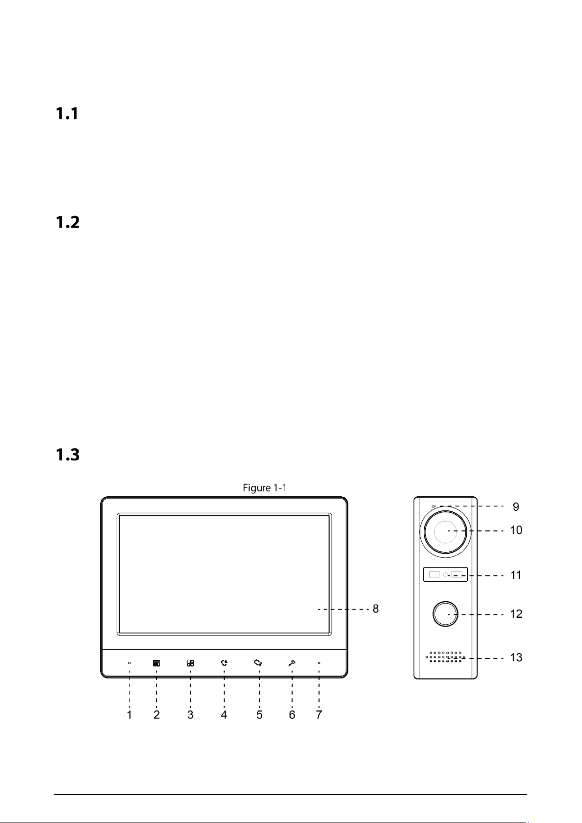
Front Panel
Front panel

2
Table 1-1 Front panel
No. Icon Description
1
–
Microphone.
2
Press to hang up the incoming call.
Take snapshots during monitoring (only supported by VTH1020J-T).
3
Wake up the screen, and bring up the menu.
For how to operate the menu, see "4 Menu Operations".
4
When someone is calling from the VTO:
Press once to do voice communication with the person.
Press twice quickly to hang up.
5
When someone is calling from the VTO:
Press to talk to the person (only supported by VTH1020J).
Press to take snapshots (only supported by VTH1020J-T).
When no one is calling:
Press once, twice, three times and four times to view live video of: VTO1,
VTO2, analog camera 1 and analog camera 2 respectively.
On any live video, press to take snapshots (only supported by VTH1020J-T).
6
When someone is calling, press to open the door where the VTO is installed.
7 – Power indicator.
8 – LCD screen.
9 – Microphone.
10 – Built-in camera.
11 – Power indicator.
12 –
Call button.
Press once to call the VTH.
Press and hold for 10 seconds to change the bell type of the VTO. The power
indicator will flash.
Press and hold for 15 seconds to turn up the bell volume of the VTO. The
power indicator will flash. When the volume reaches maximum, this step will
set it to minimum. Repeat this step to set appropriate volume.
Press and hold for 20 seconds to change to DWDR (digital wide dynamic
range)/normal mode for the VTO. The power indicator will flash.
13 – Speaker.

3
Rear Panel
Rear panel
Table 1-2 Rear panel
No. Description No. Description
1 Analog camera port 1. 6 VTH cascading port 1.
2 VTO port 1. 7 VTH cascading port 2.
3 VTO port 2. 8 VTO hanging slot.
4 Power input. 9 Wires.
5 Analog camera port 2. – –

4
2 Installation
VTH
Fix the bracket on the wall by screws, hang the VTH on the bracket, and then apply silicone sealant to
the gap between the device and the wall.
VTH installation
VTO
Install the VTO bracket on the wall, and then hang the VTO on the bracket; or install the VTO cover on
the wall, and then hang the VTO on the cover. Finally, apply silicone sealant to the gap between the
device and the wall.
VTO installation
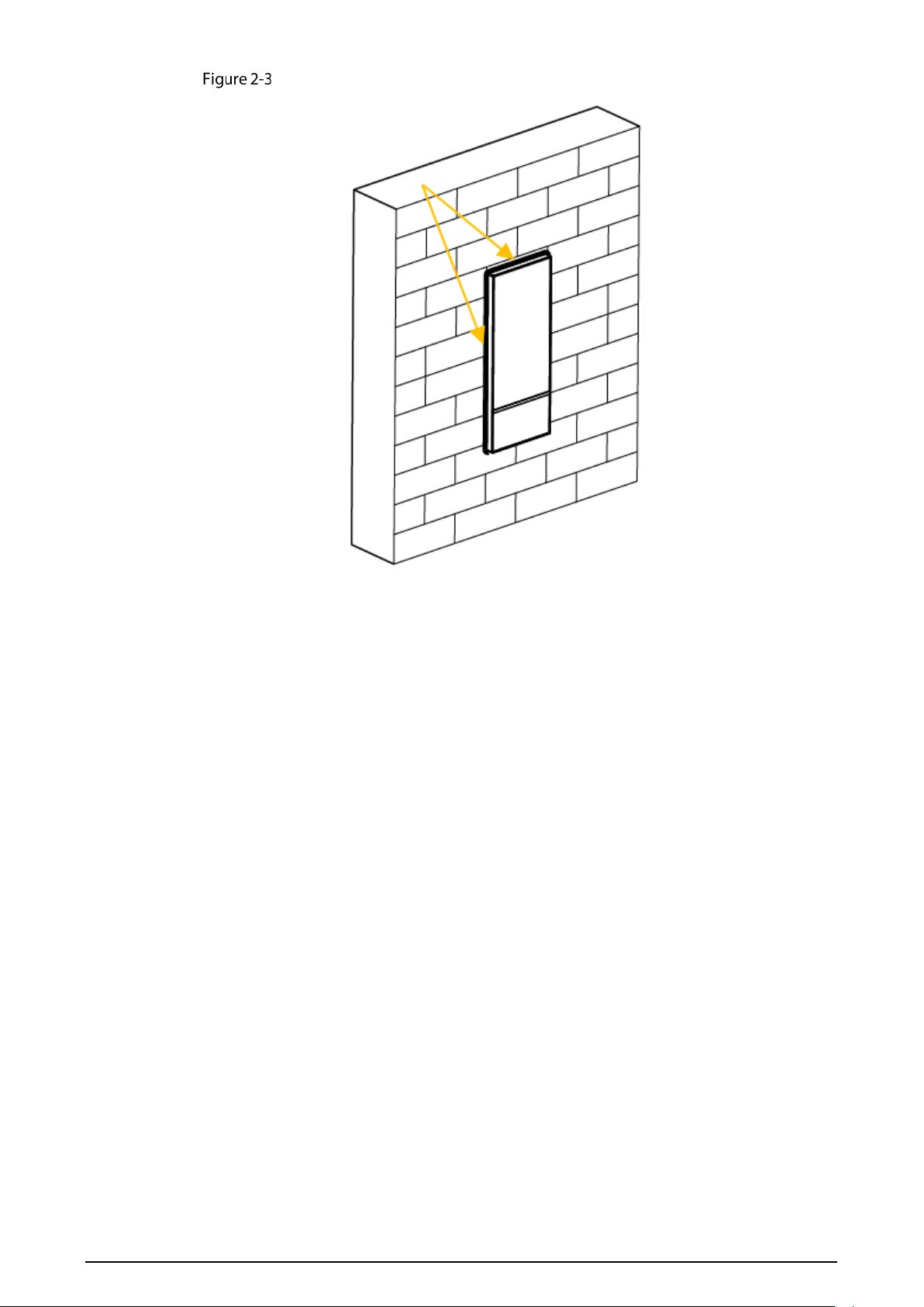
5
Apply silicone sealant to the gap between the device and the wall
6
3 Wiring
At most 2 VTOs and 3 VTHs can be wired in one communication system.
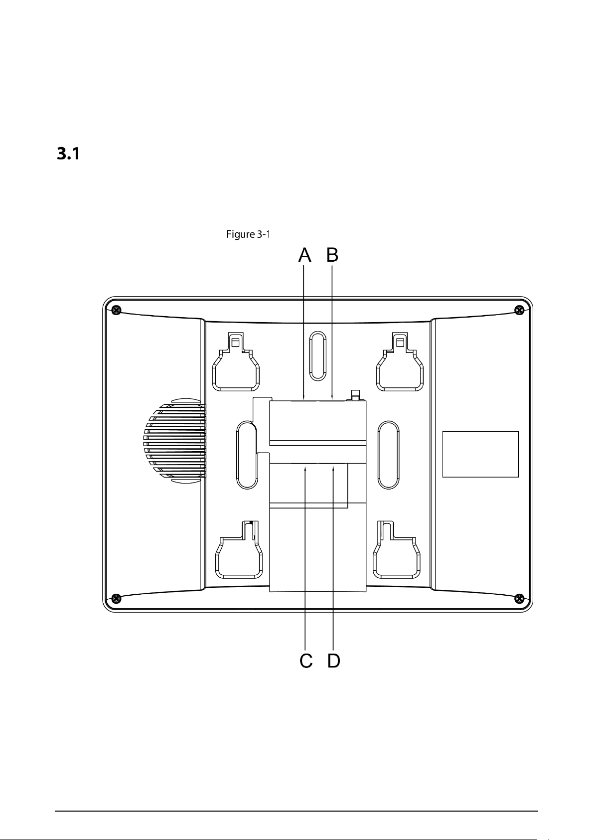
Preparations
3.1.1 Port Connection Rules
Port connection rules
Port A of an VTH can be connected to Port C of another VTH to do data communication.
Port B of an VTH can be connected to Port D of another VTH to do data communication.
Port A of an VTH cannot be connected to Port B or D of another VTH to do data communication.
Port C of an VTH cannot be connected to Port B or D of another VTH to do data communication.

7
3.1.2 Cord Specification
Depending on the distance between the VTO and VTH, you need to select RVV4 cords of different
specifications.
Table 3-1 Cord specification
Transmission Distance (TD) RVV4 Cord Specification
TD ≤ 10 m RVV4 × 0.3 mm²
10 m < TD ≤ 30 m RVV4 × 0.5 mm²
30 m < TD ≤ 50 m RVV4 × 0.75 mm²
If the distance between the VTO and VTH is more than 50 m, use coaxial cables.
Do not pull the cords violently.
During wiring, wrap the cord joints with insulated rubber tape to prevent short circuit.
Wiring One VTO and One VTH
Wiring (1)

8
Wiring One VTO and Three VTHs
Wiring (2)

9
Wiring Two VTOs and Three VTHs
Wiring (3)
The recommended analog cameras (CVBS) are HAC 1230 series.
10
4 Menu Operations
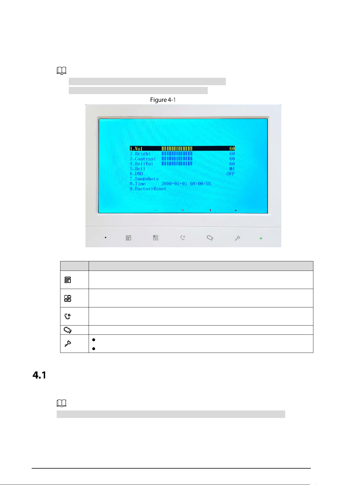
You can configure the functions of the VTH, such as volume, brightness, and more.
Only VTH1020J-T supports the Snapshots and Time functions.
All configurations will be saved after you exit the menu.
Menu
Table 4-1 Menu operations
Icon Function
Used to confirm your operation when you are using the Snapshots and Time
functions (only supported by VTH1020J-T).
Adjust Vol (volume), Bright (brightness), Contrast and BellVol (bell volume), change
Bell and turn off DND (do not disturb).
Turn up Vol (volume), Bright (brightness), Contrast and BellVol (bell volume), change
Bell, turn off DND (do not disturb), and adjust the time.
Select an item.
Exit the menu and lock the screen.
Go back to the previous interface.
Snapshots
You can take snapshots during monitoring, and view the snapshots you have taken.
The VTH can store up to 200 snapshots. If storage is full, the earlier ones will be overwritten.
Taking Snapshots
During monitoring.
11
Press to go to the monitoring image that you want.
Press , and then Successful will appear on the screen.
When a VTO is calling or in a call with a VTO, press , and then Successful will appear on the
screen.
If the calling lasts more than 1 second, a snapshot will be automatically taken.
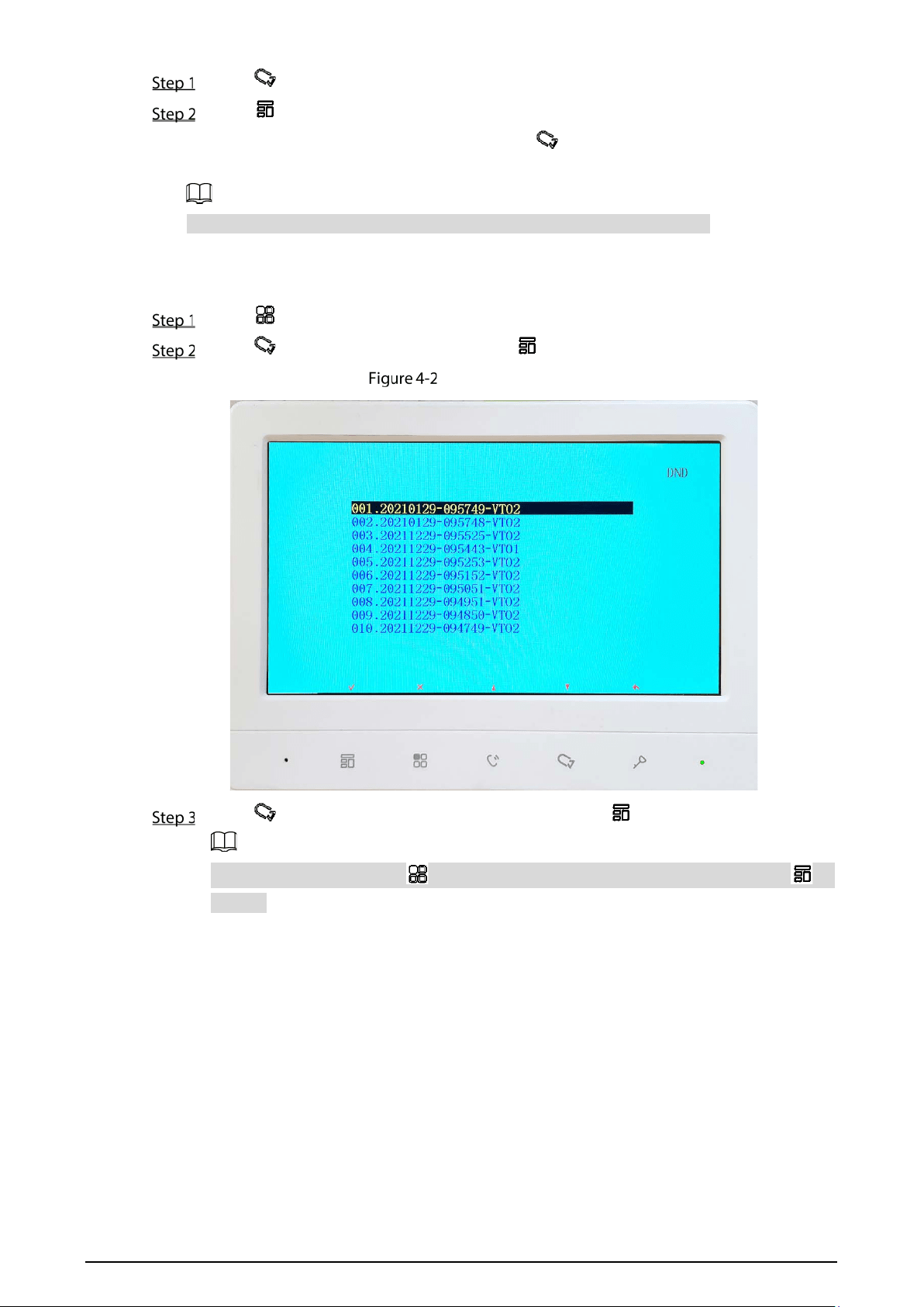
Viewing Snapshots
Press to bring up the menu.
Press , select Snapshots, and then press .
List of snapshots
Press to select the one that you need, and then press .
To delete a snapshot, press , Detele? will appear on the screen, and then press to
confirm.

12
Viewing a snapshot
Press or to view the previous or next snapshot. Or you can press to go back to
the list of snapshots, and then select the one that you need.
To delete a snapshot, press , Detele? will appear on the screen, and then press to
confirm.
Time
Press to bring up the menu.
Press to select the part of the time that you want.
Press to or to adjust the number.
Restoring to Default Settings
Press to bring up the menu.
Press to select FactoryReset.

13
Confirm your operation
Press , and then the device will restart.