Loading ...
Loading ...
Loading ...
12 49-2000733 Rev. 1
Installation Preparation
INSTALLATION INSTRUCTIONS
VENTING OPTIONS
• The downdraft vent is shipped with the discharge
outlet pointing straight down and can be changed to
the left or right side. To avoid interference problems,
the downdraft vent cannot be vented to the right
when installed with a GE or Monogram gas cooktop,
or with a GE or Monogram non-induction electric
cooktop.
• The blower outlet is sized for 3-1/4” x 10” and can
be transitioned to 6” round.
The blower is shipped with its discharge facing
DOWN. Follow these steps ONLY if:
• the position of the blower discharge needs to be
moved so ductwork does not interfere with floor
joists, plumbing or wiring below.
• it is necessary to rotate the blower discharge to the
RIGHT or LEFT.
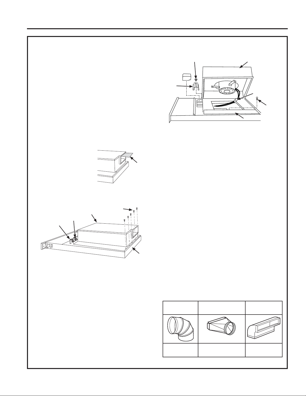
Place the unit on its back on
a table or work surface.
Pull out the bubble wrap
sheet. Make sure nothing is
left inside.
DOWN DISCHARGE - MOVING BLOWER LEFT OR
RIGHT
1. Loosen the 4 nuts and 2 clamp channels.
2. Remove the 5 screws on the bottom. These 5
screws are for shipping and do not need to be
re-tightened.
3. Slide blower to desired position.
4. Use supplied cover plate to close open space (if
any).
5. Tighten wing nuts to secure top of blower and use
sheet metal screws through bottom flange to secure
bottom of blower.
LEFT OR RIGHT DISCHARGE
1. Remove the 4 nuts and 2 clamp channels.
2. Remove the 5 screws on the bottom. These 5
screws are for shipping and do not need to be
re-tightened.
3. Carefully lift blower and disconnect motor plug if
necessary. Reposition blower and RECONNECT
MOTOR PLUG.
4. Use supplied cover plate to close open space (if
any).
5. Replace clamp channels and use nuts to secure the
blower in its new position.
6. Use sheet metal screws through bottom flange to
secure bottom of blower.
For best performance: Choose the ducting option
which allows the shortest length of ductwork and a
minimum number of elbows and transitions. Check
location of floor joists, wall studs, electrical wiring or
plumbing for possible interference.
NOTE: The unit is shipped with the 3-1/4" x 10"
discharge facing DOWN. See “CHANGING BLOWER
DIRECTION” on page 3, if necessary.
The system will operate most efficiently when the
ductwork does not exceed 40 feet of equivalent duct.
The chart, below, shows equivalent feet of elbows and
transitions. The number of feet of straight duct plus the
equivalent feet of transitions and/or elbows to be used
should equal 40 feet or less.
Nut
Blower
Motor Plug
Sheet
Metal
Screw
Cover Plate
Clamp
Channel
Nuts
Blower
Clamp
Channel
Sheet Metal
Screws
Bottom
Flange
6" Round
Elbow
3-1/4"x10" to 6"
Round Transition
3-1/4"x10"
90° Elbow
equals 6 ft. of
straight duct
equals 2 ft. of
straight duct
equals 8 ft. of
straight duct
Bubble
Wrap Sheet
Loading ...
Loading ...
Loading ...