Loading ...
Loading ...
Loading ...
16
E
Checking Laser Accuracy
The laser tools are sealed and calibrated at the factory.
It is recommended that you perform an accuracy check
prior to using the laser for the rst time (in case the
laser was exposed to extreme temperatures) and then
regularly to ensure the accuracy of your work. When
performing any of the accuracy checks listed in this
manual, follow these guidelines:
• Use the largest area/distance possible, closest to the
operating distance. The greater the area/distance,
the easier to measure the accuracy of the laser.
• Place the laser on a smooth, at, stable surface that
is level in both directions.
• Mark the center of the laser beam.
Horizontal Beam - Scan Direction
Checking the horizontal scan calibration of the laser
requires two walls 30′ (9m) apart. It is important to
conduct a calibration check using a distance no shorter
than the distance of the applications for which the tool
will be used.
1.
Place the laser against the end of the wall on a
smooth, at, stable surface that is level in both
directions (Figure
D
1
).
2.
Move the Power/Transport Lock switch to the right
to turn the laser ON.
3.
Press to turn on the horizontal beam.
4.
At least 30′ (9m) apart along the laser beam, mark
a
and
b
.
5.
Turn the laser 180º.
6.
Adjust the height of the laser so the center of the
beam is aligned with
a
(Figure
D
2
).
7.
Directly above or below
b
, mark
c
along the laser
beam (Figure
D
3
).
8.
Measure the vertical distance between
b
and
c
.
9.
If your measurement is greater than the Allowable
Distance Between
b
and
c
for the
corresponding Distance Between Walls in the
following table, the laser must be serviced at an
authorized service center.
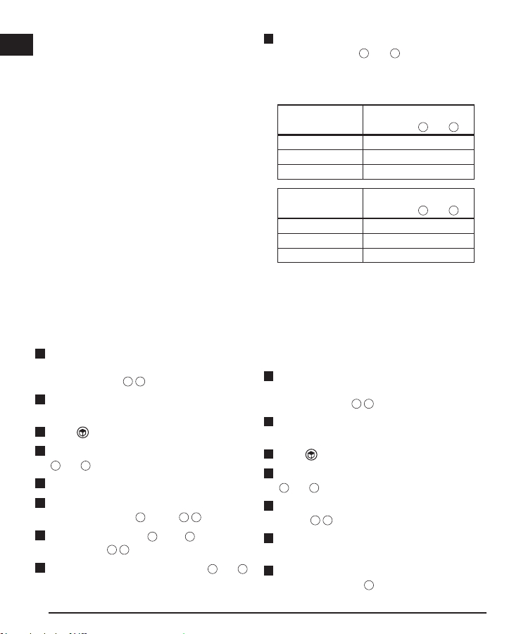
Distance
Between Walls
Allowable Distance
Between
b
and
c
30’ 1/4”
40’ 5/16”
50’ 13/32”
Distance
Between Walls
Allowable Distance
Between
b
and
c
9.0 m 6.2 mm
12.0 m 8.3 mm
15.0 m 10.4 mm
Horizontal Beam - Pitch Direction
Checking the horizontal pitch calibration of the
laser requires a single wall at least 30′ (9m) long.
It is important to conduct a calibration check using
a distance no shorter than the distance of the
applications for which the tool will be used.
1.
Place the laser against the end of the wall on a
smooth, at, stable surface that is level in both
directions (Figure
E
1
).
2.
Move the Power/Transport Lock switch to the right
to turn the laser ON.
3.
Press to turn on the horizontal beam.
4.
At least 30′ (9m) apart along the laser beam, mark
a
and
b
.
5.
Move the laser to the opposite end of the wall
(Figure
E
2
).
6.
Position the laser toward the rst end of the same
wall and parallel to the adjacent wall.
7.
Adjust the height of the laser so the center of the
beam is aligned with
b
.
V
Checking the vertical (plumb) calibration of the
laser can be most accurately done when there is a
substantial amount of vertical height available, ideally
30’ (9m), with one person on the oor positioning
the laser and another person near a ceiling to mark
the position of the beam. It is important to conduct a
calibration check using a distance no shorter than the
distance of the applications for which the tool will be
used.
Place the laser on a smooth, at, stable surface
Loading ...
Loading ...
Loading ...