
Projector
PA803U/PA723U/PA653U/
PA853W/PA703W/PA903X
User’s Manual
Please visit our web site for User’s Manual in the latest version:
http://www.nec-display.com/dl/en/pj_manual/lineup.html
• ThePA723UandPA703WarenotdistributedinNorthAmerica.
ModelNo.
NP-PA803U/NP-PA723U/NP-PA653U/NP-PA853W/NP-PA703W/NP-PA903X

Ver.24/17
• Apple,Mac,MacOS,andMacBookaretrademarksofAppleInc.registeredintheU.S.andothercountries.
• Microsoft,Windows,WindowsVista,Internet Explorer,.NET FrameworkandPowerPointareeither a registered
trademarkortrademarkofMicrosoftCorporationintheUnitedStatesand/orothercountries.
• MicroSaverisaregisteredtrademarkofKensingtonComputerProductsGroup,adivisionofACCOBrands.
• AccuBlend,NaViSet,andVirtualRemotearetrademarksorregisteredtrademarksofNECDisplaySolutions,Ltd.
inJapan,intheUnitedStateandothercountries.
• ThetermsHDMIandHDMIHigh-DenitionMultimediaInterface,andtheHDMILogoaretrademarksorregistered
trademarksofHDMILicensing,LLCintheUnitedStatesandothercountries.
• DisplayPortandDisplayPortComplianceLogoaretrademarksownedbytheVideoElectronicsStandardsAssocia-
tion.
• HDBaseT™isatrademarkofHDBaseTAlliance.
• TrademarkPJLinkisatrademarkappliedfortrademarkrightsinJapan,theUnitedStatesofAmericaandother
countries and areas.
• Blu-rayisatrademarkofBlu-rayDiscAssociation.
• CRESTRONandROOMVIEWareregisteredtrademarksofCrestronElectronics,Inc.intheUnitedStatesandother
countries.
• ExtronandXTPareregisteredtrademarksofRGBSystems,Inc.intheUnitedStates.
• EthernetiseitheraregisteredtrademarkortrademarkofFujiXeroxCo.,Ltd.
• Otherproductandcompanynamesmentionedinthisuser’smanualmaybethetrademarksorregisteredtrademarks
of their respective holders.
• VirtualRemoteToolusesWinI2C/DDClibrary,©NicomsoftLtd.
NOTES
(1)Thecontentsofthisuser’smanualmaynotbereprintedinpartorwholewithoutpermission.
(2)Thecontentsofthisuser’smanualaresubjecttochangewithoutnotice.
(3)Greatcarehasbeentakeninthepreparationofthisuser’smanual;however,shouldyounoticeanyquestionable
points,errorsoromissions,pleasecontactus.
(4)Notwithstandingarticle(3),NECwillnotberesponsibleforanyclaimsonlossofprotorothermattersdeemed
toresultfromusingtheProjector.
i
Important Information
Safety Cautions
Precautions
PleasereadthismanualcarefullybeforeusingyourNECprojectorandkeepthemanualhandyforfuturereference.
CAUTION
Toturnoffmainpower,besuretoremovetheplugfrompoweroutlet.
Thepoweroutletsocketshouldbeinstalledasneartotheequipmentaspossible,andshouldbeeasily
accessible.
CAUTION
TOPREVENTSHOCK,DONOTOPENTHECABINET.
THEREAREHIGH-VOLTAGECOMPONENTSINSIDE.
REFERSERVICINGTOQUALIFIEDSERVICEPERSONNEL.
Thissymbolwarnstheuserthatuninsulatedvoltagewithintheunitmaybesufficienttocauseelectrical
shock.Therefore,itisdangeroustomakeanykindofcontactwithanypartinsideoftheunit.
Thissymbolalertstheuserthatimportantinformationconcerningtheoperationandmaintenanceofthis
unit has been provided.
Theinformationshouldbereadcarefullytoavoidproblems.
WARNING:TOPREVENTFIREORSHOCK,DONOTEXPOSETHISUNITTORAINORMOISTURE.
DONOTUSETHISUNIT’SPLUGWITHANEXTENSIONCORDORINANOUTLETUNLESSALLTHEPRONGS
CANBEFULLYINSERTED.
DOC Compliance Notice (for Canada only)
ThisClassBdigitalapparatuscomplieswithCanadianICES-003.
Machine Noise Information Regulation - 3. GPSGV,
Thehighestsoundpressurelevelislessthan70dB(A)inaccordancewithENISO7779.
CAUTION
Avoiddisplayingstationaryimagesforaprolongedperiodoftime.
DoingsocanresultintheseimagesbeingtemporarilysustainedonthesurfaceoftheLCDpanel.
Ifthisshouldhappen,continuetouseyourprojector.Thestaticbackgroundfrompreviousimageswill
disappear.
Disposing of your used product
In the European Union
EU-widelegislationasimplementedineachMemberStaterequiresthatusedelectricalandelectronicprod-
uctscarryingthemark(left)mustbedisposedofseparatelyfromnormalhouseholdwaste.Thisincludes
projectorsandtheirelectricalaccessories.Whenyoudisposeofsuchproducts,pleasefollowtheguidance
ofyourlocalauthorityand/orasktheshopwhereyoupurchasedtheproduct.
Aftercollectingtheusedproducts,theyarereusedandrecycledinaproperway.Thiseffortwillhelpusreduce
thewastesaswellasthenegativeimpacttothehumanhealthandtheenvironmentattheminimumlevel.
ThemarkontheelectricalandelectronicproductsonlyappliestothecurrentEuropeanUnionMemberStates.
Outside the European Union
IfyouwishtodisposeofusedelectricalandelectronicproductsoutsidetheEuropeanunion,pleasecontact
yourlocalauthorityandaskforthecorrectmethodofdisposal.
For EU:Thecrossed-outwheeledbinimpliesthatusedbatteriesshouldnotbeputtothegeneralhousehold
waste!Thereisaseparatecollectionsystemforusedbatteries,toallowpropertreatmentandrecyclingin
accordancewithlegislation.
According the EU directive 2006/66/EC, the battery can’t be disposed improperly. The battery shall be sepa-
rated to collect by local service.

ii
Important Information
WARNING TO CALIFORNIA RESIDENTS:
Handlingthecablessuppliedwiththisproductwillexposeyoutolead,achemicalknowntotheStateofCalifornia
tocausebirthdefectsorotherreproductiveharm.WASHHANDSAFTERHANDLING.
RF Interference (for USA only)
WARNING
The Federal Communications Commission does not allow any modications or changes to the unit EXCEPT
thosespeciedbyNECDisplaySolutionsofAmerica,Inc.inthismanual.Failuretocomplywiththisgovernment
regulationcouldvoidyourrighttooperatethisequipment.Thisequipmenthasbeentestedandfoundtocomply
withthelimitsforaClassBdigitaldevice,pursuanttoPart15oftheFCCRules.Theselimitsaredesignedto
providereasonableprotectionagainstharmfulinterferenceinaresidentialinstallation.Thisequipmentgenerates,
uses,andcanradiateradiofrequencyenergyand,ifnotinstalledandusedinaccordancewiththeinstructions,
maycauseharmfulinterferencetoradiocommunications.However,thereisnoguaranteethatinterferencewill
not occur in a particular installation.
Ifthisequipmentdoescauseharmfulinterferencetoradioortelevisionreception,whichcanbedeterminedby
turningtheequipmentoffandon,theuserisencouragedtotrytocorrecttheinterferencebyoneormoreofthe
followingmeasures:
• Reorientorrelocatethereceivingantenna.
• Increasetheseparationbetweentheequipmentandreceiver.
• Connecttheequipmentintoanoutletonacircuitdifferentfromthattowhichthereceiverisconnected.
• Consultthedealeroranexperiencedradio/TVtechnicianforhelp.
ForUKonly:InUK,aBSapprovedpowercordwithmouldedplughasaBlack(veAmps)fuseinstalledforusewith
thisequipment.Ifapowercordisnotsuppliedwiththisequipmentpleasecontactyoursupplier.
Important Safeguards
Thesesafetyinstructionsaretoensurethelonglifeofyourprojectorandtopreventreandshock.Pleasereadthem
carefullyandheedallwarnings.
Installation
• Donotplacetheprojectorinthefollowingconditions:
- onanunstablecart,stand,ortable.
- nearwater,baths,ordamprooms.
- indirectsunlight,nearheaters,orheatradiatingappliances.
- inadusty,smokyorsteamyenvironment.
- onasheetofpaperorcloth,rugsorcarpets.
• Donotinstallandstoretheprojectorinthebelowcircumstances.Failuretodosomaycauseofmalfunction.
- Inpowerfulmagneticelds
- Incorrosivegasenvironment
- Outdoors
• Ifyouwishtohavetheprojectorinstalledontheceiling:
- Donotattempttoinstalltheprojectoryourself.
- Theprojectormustbeinstalledbyqualiedtechniciansinordertoensureproperoperationandreducetherisk
of bodily injury.
- Inaddition,theceilingmustbestrongenoughtosupporttheprojectorandtheinstallationmustbeinaccordance
withanylocalbuildingcodes.
- Please consult your dealer for more information.
iii
Important Information
WARNING
• Donotcoverthelenswiththelenscaporequivalentwhiletheprojectorison.Doingsocanleadtomeltingof
thecapduetotheheatemittedfromthelightoutput.
• Donotplaceanyobjects,whichareeasilyaffectedbyheat,infrontoftheprojectorlens.Doingsocouldlead
totheobjectmeltingfromtheheatthatisemittedfromthelightoutput.
Thebelowpictogramindicatedonthecabinetmeanstheprecautionforavoidingtoplaceobjectsinfrontofthe
projector lens.
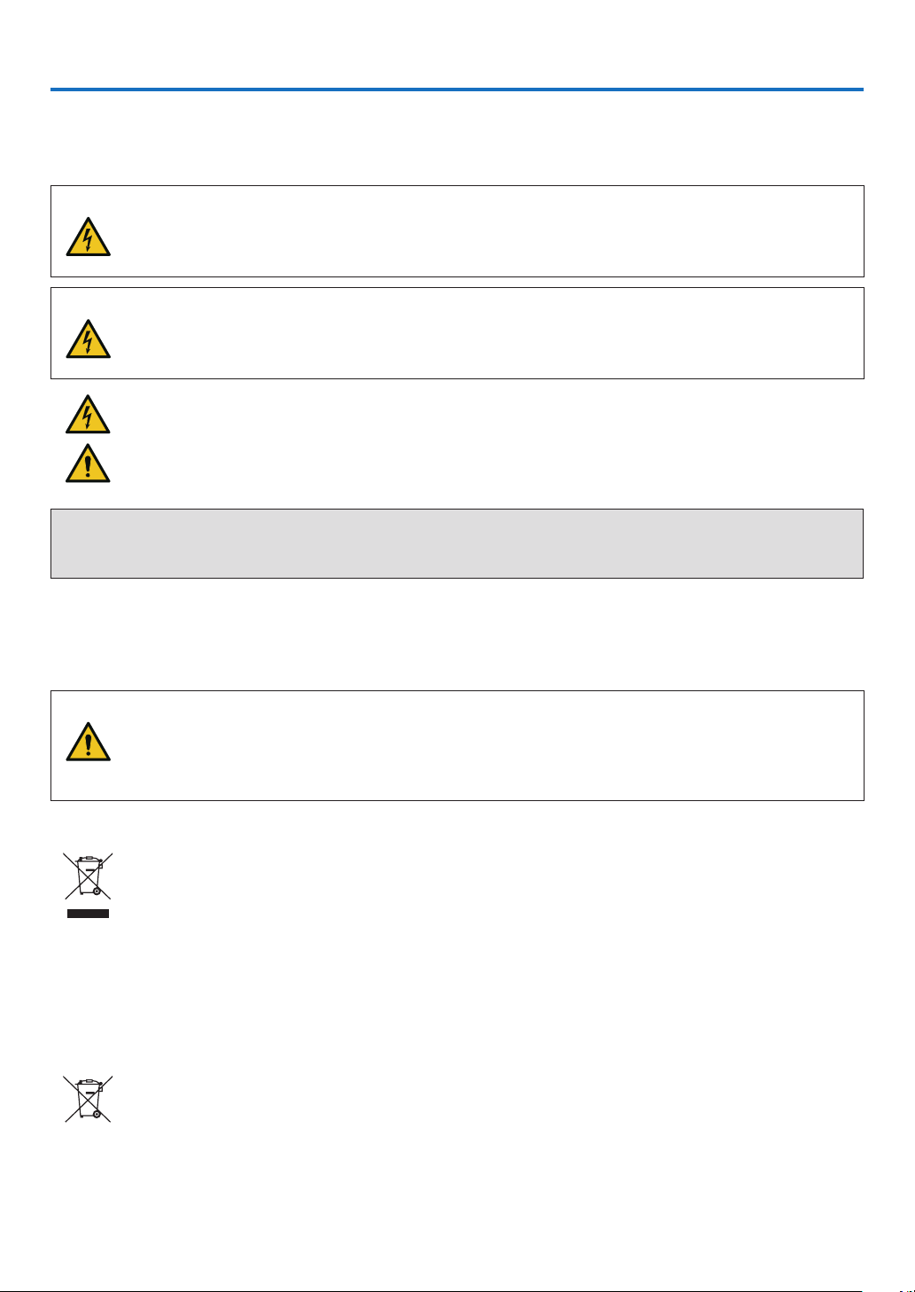
Thisprojectorcanbeinstalledanyanglewithinvertical.
Forportraitinstallation,installtheprojectorwiththeintakeventatthebottom.Observeprecautionsforportraitinstallation.
* Acustomizedstandisrequiredtobeattachedtotheprojector.(→page150)
130 mm or more
Fire and Shock Precautions
• Ensurethatthereissufficientventilationandthatventsareunobstructedtopreventthebuild-upofheatinsideyour
projector.Allowenoughspacebetweenyourprojectorandawall.(→pageviii)
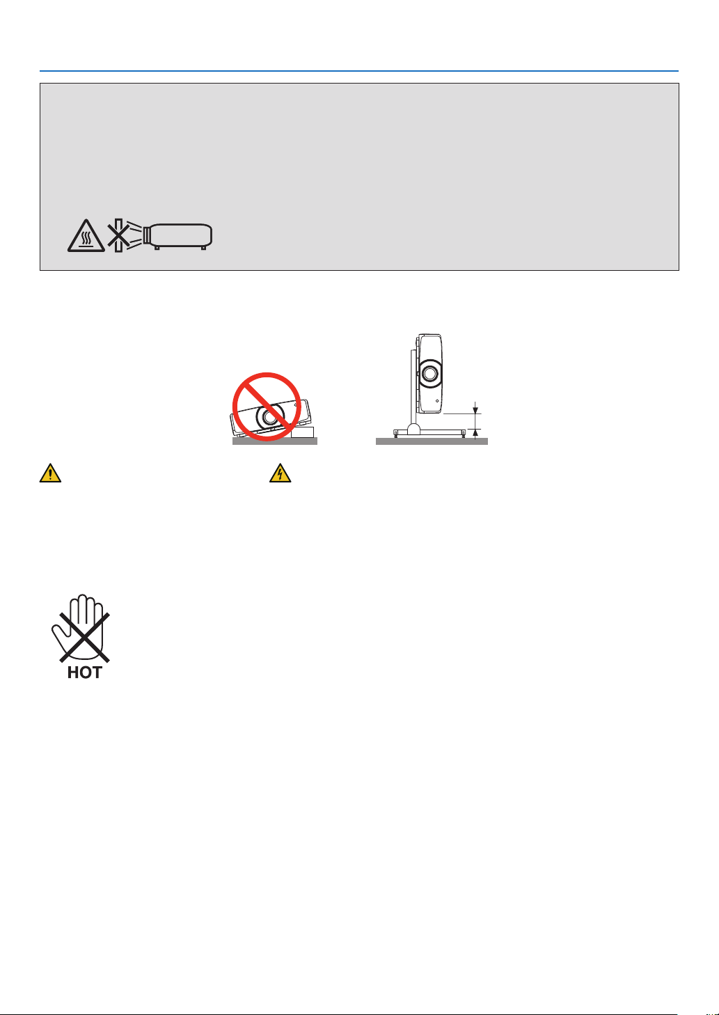
• Donottrytotouchtheexhaustventsontheleftrearandtherear(whenseenfromthefront)asitcanbecomeheated
while the projector is turned on and immediately after the projector is turned off. Parts of the projector may become
temporarilyheatediftheprojectoristurnedoffwiththePOWERbuttonoriftheACpowersupplyisdisconnected
duringnormalprojectoroperation.Usecautionwhenpickinguptheprojector.
Thebelowpictogrammeansthecautiontohotarea.
• Preventforeignobjectssuchaspaperclipsandbitsofpaperfromfallingintoyourprojector.Donotattempttoretrieve
anyobjectsthatmightfallintoyourprojector.Donotinsertanymetalobjectssuchasawireorscrewdriverintoyour
projector.Ifsomethingshouldfallintoyourprojector,disconnectitimmediatelyandhavetheobjectremovedbya
qualiedservicepersonnel.
• Donotplaceanyobjectsontopoftheprojector.
• Donottouchthepowerplugduringathunderstorm.Doingsocancauseelectricalshock.
• Theprojectorisdesignedtooperateonapowersupplyof100-240VAC50/60Hz.Ensurethatyourpowersupply
tsthisrequirementbeforeattemptingtouseyourprojector.
• Makesuretomountthepowercordstopperbeforeattemptingtouseyourprojector.Pleaserefertopage15 about
the power cord stopper.

iv
Important Information
• Donotlookintothelenswhiletheprojectorison.Seriousdamagetoyoureyescouldresult.Thefollowinglabel,
thatisindicatedatthelens-mounting-sectionontheprojectorcabinet,describesthisprojectoriscategorizedinthe
riskgroup2ofIEC62471-5:2015.Aswithanybrightlightsource,donotstareintothebeam,RG2IEC62471-5:
2015.
• Performtheadjustmentfrombehindorfromthesideoftheprojector.Adjustingfromthefrontcouldexposeyour
eyestostronglightwhichcouldinjurethem.
• Keepanyitems(magnifyingglassetc.)outofthelightpathoftheprojector.Thelightpathbeingprojectedfromthe
lensisextensive,thereforeanykindofabnormalobjectsthatcanredirectlightcomingoutofthelens,cancause
anunpredictableoutcomesuchasareorinjurytotheeyes.
• Donotplaceanyobjects,whichareeasilyaffectedbyheat,infrontofaprojectorexhaustvent.
Doingsocouldleadtotheobjectmeltingorgettingyourhandsburnedfromtheheatthatisemittedfromtheexhaust
vent.
• Handlethepowercordcarefully.Adamagedorfrayedpowercordcancauseelectricshockorre.
- Donotuseanypowercordotherthantheonesuppliedwiththeprojector.
Ifthesuppliedpowercorddoesnotsatisfyrequirementsofyourregion'ssafetystandard,andvoltageandcurrent
foryourregion,makesuretousethepowercordthatconformstoandsatisesthem.
- Donotbendortugthepowercordexcessively.
- Donotplacethepowercordundertheprojector,oranyheavyobject.
- Donotcoverthepowercordwithothersoftmaterialssuchasrugs.
- Donotheatthepowercord.
- Donothandlethepowerplugwithwethands.
• Turnofftheprojector,unplugthepowercordandhavetheprojectorservicedbyaqualiedservicepersonnelunder
thefollowingconditions:
- Whenthepowercordorplugisdamagedorfrayed.
- Ifliquidhasbeenspilledintotheprojector,orifithasbeenexposedtorainorwater.
- Iftheprojectordoesnotoperatenormallywhenyoufollowtheinstructionsdescribedinthisuser’smanual.
- Iftheprojectorhasbeendroppedorthecabinethasbeendamaged.
- Iftheprojectorexhibitsadistinctchangeinperformance,indicatinganeedforservice.
• Disconnectthepowercordandanyothercablesbeforecarryingtheprojector.
• Turnofftheprojectorandunplugthepowercordbeforecleaningthecabinetorreplacingthelamp.
• Turnofftheprojectorandunplugthepowercordiftheprojectorisnottobeusedforanextendedperiodoftime.
• WhenusingaLANcable:
Forsafety,donotconnecttotheconnectorforperipheraldevicewiringthatmighthaveexcessivevoltage.

v
Important Information
CAUTION
• Donotusethetilt-footforpurposesotherthanoriginallyintended.Misusessuchasgrippingthetilt-footorhang-
ingonthewallcancausedamagetotheprojector.
• Donotholdthecablecoverwhilemovingtheprojectorordonotapplyexcessiveforcetothecablecover.Doing
somaydamagethecablecover,resultingininjury.
• Besuretotightenthescrewsafterattachingthecablecover.Failuretodosomaycausethecablecovertocome
offandfall,resultingininjuryordamagetothecablecover.
• Donotputbundledcablesinthecablecover.Doingsomaydamagethepowercord,resultinginare.
• Select[HIGH]inFanmodeifyoucontinuetousetheprojectorforconsecutivedays.(Fromthemenu,select
[SETUP]→[OPTIONS(1)]→[FANMODE]→[MODE]→[HIGH].)
• Donotmovetheprojectorbyholdingthecablecover.Doingsomayresultintheprojectorfallingorcausing
injury.
• Donotunplugthepowercablefromthewalloutletorprojectorwhentheprojectorispoweredon.Doingsocan
causedamagetotheACINterminaloftheprojectorand(or)theprongplugofthepowercable.
ToturnofftheACpowersupplyunderthestatetheprojectorisON,useapowerstripequippedwithaswitch
andabreaker.
• DonotturnofftheACpowerfor60secondsafterthelampisturnedonandwhilethePOWERindicatorisblink-
ingblue.Doingsocouldcauseprematurelampfailure.
• Thepowerplugmaybeunpluggedfromthesocketafterturningoffthepowersupplyoftheprojector.
ImmediatelyafterturningofftheACpowersupplyduringvideoprojection,orafterturningoffthepowersupply
oftheprojector,theprojectorcabinetmaybecomeveryhotmomentarily.Pleasehandlewithcare.
Caution on Handling the Optional Lens
Whenshippingtheprojectorwiththelens,removethelensbeforeshippingtheprojector.Alwaysattachthedustcap
tothelenswheneveritisnotmountedontheprojector.Thelensandthelensshiftmechanismmayencounterdam-
agecausedbyimproperhandlingduringtransportation.
Donotholdthelenspartwhencarryingtheprojector.
Doingsocouldcausethefocusringtorotate,resultinginaccidentaldroppingoftheprojector.
Intheconditiontheprojectorisnolensmounted,donotputyourhandsinthelensmountopeningforcarryingthe
projector.
Keephandsawayfromthelensmountingportionwhileperformingalensshift.Failuretodosocouldresultinngers
beingpinchedbythemovinglens.
Remote Control Precautions
• Handletheremotecontrolcarefully.
• Iftheremotecontrolgetswet,wipeitdryimmediately.
• Avoidexcessiveheatandhumidity.
• Donotshort,heat,ortakeapartbatteries.
• Donotthrowbatteriesintore.
• Ifyouwillnotbeusingtheremotecontrolforalongtime,removethebatteries.
• Ensurethatyouhavethebatteries’polarity(+/−)alignedcorrectly.
• Donotusenewandoldbatteriestogether,orusedifferenttypesofbatteriestogether.
• Disposeofusedbatteriesaccordingtoyourlocalregulations.
• Replacetwobatteriesatthesametimewiththequitesameonesthathasbeeninstalledintheremotecontrolor
AAsizedalkalisbatterythatisconformedtoIEC60086-5.
Note for Canadian Environmental Protection Act, 1999
Thelamp(s)inthisproductcontainsmercury.Pleasedisposeaccordingtoyourlocalauthoritylaw.
FORMOREINFORMATION,CONTACT:
NECDisplaySolutionsofAmerica,Inc.
500ParkBoulevard,Suite1100,Itasca,Illinois60143-1248
TELEPHONE800-836-0655
www.necdisplay.com

vi
Important Information
Note for US Residents
Thelampinthisproductcontainsmercury.PleasedisposeaccordingtoLocal,StateorFederalLaws.
Lamp Replacement
• Usethespeciedlampforsafetyandperformance.
• Toreplacethelamp,followallinstructionsprovidedonpage156.
• Besuretoreplacethelampandlterwhenthemessage[THE LAMP HAS REACHED THE END OF ITS USABLE
LIFE. PLEASE REPLACE THE LAMP. USE THE SPECIFIED LAMP FOR SAFETY AND PERFORMANCE.]
appears.Ifyoucontinuetousethelampafterthelamphasreachedtheendofitsusablelife,thelampbulbmay
shatter,andpiecesofglassmaybescatteredinthelampcase.Donottouchthemasthepiecesofglassmaycause
injury.
Ifthishappens,contactyourdealerforlampreplacement.
A Lamp Characteristic
Theprojectorhasadischargelampforspecialpurposesasalightsource.
Alamphasacharacteristicthatitsbrightnessgraduallydecreaseswithage.Alsorepeatedlyturningthelampon
andoffwillincreasethepossibilityofitslowerbrightness.
CAUTION:
• DONOTTOUCHTHELAMPimmediatelyafterithasbeenused.Itwillbeextremelyhot.Turntheprojectoroff
andthendisconnectthepowercord.Allowatleastonehourforthelamptocoolbeforehandling.
• Whenremovingthelampfromaceiling-mountedprojector,makesurethatnooneisundertheprojector.Glass
fragmentscouldfallifthelamphasbeenburnedout.
About High Altitude mode
• Set[FANMODE]to[HIGHALTITUDE]whenusingtheprojectorataltitudesapproximately5500feet/1700meters
orhigher.
Usingtheprojectorataltitudesapproximately5500feet/1700metersorhigherwithoutsettingto[HIGHALTITUDE]
cancausetheprojectortooverheatandtheprotectorcouldshutdown.Ifthishappens,waitacoupleminutesand
turn on the projector.
• Usingtheprojectorataltitudeslessthanapproximately5500feet/1700metersandsettingto[HIGHALTITUDE]
cancausethelamptoovercool,causingtheimagetoicker.Switch[FANMODE]to[AUTO].
• Usingtheprojectorataltitudesapproximately5500feet/1700metersorhighercanshortenthelifeofopticalcom-
ponents such as the lamp.
About Copyright of original projected pictures:
Pleasenotethatusingthisprojectorforthepurposeofcommercialgainortheattractionofpublicattentioninavenue
suchasacoffeeshoporhotelandemployingcompressionorexpansionofthescreenimagewiththefollowingfunc-
tionsmayraiseconcernabouttheinfringementofcopyrightswhichareprotectedbycopyrightlaw.
[ASPECTRATIO],[KEYSTONE],Magnifyingfeatureandothersimilarfeatures.
Turkish RoHS information relevant for Turkish market
EEE Yönetmeliğine Uygundur.

vii
Important Information
Health precautions to users viewing 3D images
Beforeviewing,besuretoreadhealthcareprecautionsthatmaybefoundintheuser’smanualincludedwithyour3D
eyeglassesoryour3DcompatiblecontentsuchasBlu-rayDiscs,videogames,computer’svideolesandthelike.
Toavoidanyadversesymptoms,heedthefollowing:
• Donotuse3Deyeglassesforviewinganymaterialotherthan3Dimages.
• Allowadistanceof2m/7feetorgreaterbetweenthescreenandauser.Viewing3Dimagesfromtooclosea
distance can strain your eyes.
• Avoidviewing3Dimagesforaprolongedperiodoftime.Takeabreakof15minutesorlongeraftereveryhour
ofviewing.
• Ifyouoranymemberofyourfamilyhasahistoryoflight-sensitiveseizures,consultadoctorbeforeviewing3D
images.
• Whileviewing3Dimages,ifyougetsicksuchasnausea,dizziness,queasiness,headache,eyestrain,blurry
vision,convulsions,andnumbness,stopviewingthem.Ifsymptomsstillpersist,consultadoctor.
• View3Dimagesfromthefrontofthescreen.Viewingfromananglemaycausefatigueoreyestrain.
AUTO POWER OFF Function
Thefactorydefaultsettingfor[AUTOPOWEROFF]is15minutes.Ifnoinputsignalisreceivedandnooperationis
performedontheprojectorduring15minutes,theprojectorisautomaticallypoweredoffforsavingthepowercon-
sumption.Inordertocontroltheprojectorbyanexternaldevice,setthe[AUTOPOWEROFF]to[OFF].Pleaserefer
page133 for details.
viii
Important Information
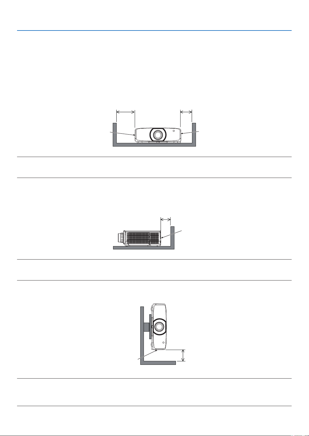
Clearance for Installing the Projector
Allowampleclearancebetweentheprojectoranditssurroundingsasshownbelow.
Thehightemperatureexhaustcomingoutofthedevicemaybesuckedintothedeviceagain.
AvoidinstallingtheprojectorinaplacewhereairmovementfromtheHVACisdirectedattheprojector.
HeatedairfromtheHVACcanbetakeninbytheprojector'sintakevent.Ifthishappens,thetemperatureinsidethe
projectorwillrisetoohighcausingtheover-temperatureprotectortoautomaticallyturnofftheprojectorspower.
Example 1 – If there are walls on both sides of the projector.
20 cm/7.9" or greater 13 cm/5.1" or greater
Filter cover
(Intake vent)
Lamp cover
NOTE:
The drawing shows the proper clearance required for the left and right of the projector assuming sufficient clearance has been kept
for the front, back and top of the projector.
Example 2 – If there is a wall behind the projector.
10 cm/3.9" or greater
Exhaust vent
NOTE:
The drawing shows the proper clearance required for the back of the projector assuming sufficient clearance has been kept for the
right, left and top of the projector.
Example 3 – In the case of portrait projection.
Filter cover
(Intake vent)
13 cm/5.1" or greater
NOTE:
• Thedrawingshowstheproperclearancerequiredforundertheprojectorassumingsufcientclearancehasbeenkeptforthe
front, rear and top of the projector.
• Seepage150 for an installation example on portrait projection.

ix
Table of Contents
Important Information ............................................................................................i
1. Introduction ...........................................................................................................1
❶What’sintheBox? ..........................................................................................................1
❷IntroductiontotheProjector ............................................................................................ 2
CongratulationsonYourPurchaseoftheProjector ...................................................2
Installation ................................................................................................................. 2
Videos .......................................................................................................................2
Network .....................................................................................................................3
Energy-saving ...........................................................................................................3
Maintenance .............................................................................................................4
Aboutthisuser’smanual ........................................................................................... 5
❸PartNamesoftheProjector ...........................................................................................6
Front/Top ...................................................................................................................6
Rear ..........................................................................................................................8
Controls/IndicatorPanel ............................................................................................9
Terminals ................................................................................................................ 10
❹PartNamesoftheRemoteControl ............................................................................... 11
BatteryInstallation ..................................................................................................12
RemoteControlPrecautions ...................................................................................12
OperatingRangeforWirelessRemoteControl .......................................................13
2. Projecting an Image (Basic Operation) ...............................................14
❶FlowofProjectinganImage .........................................................................................14
❷ConnectingYourComputer/ConnectingthePowerCord ..............................................15
Usingthepowercordstopper .................................................................................15
❸TurningontheProjector ................................................................................................17
PerformingLensCalibration ...................................................................................17
NoteonStartupscreen(MenuLanguageSelectscreen) ....................................... 18
❹SelectingaSource .......................................................................................................19
Selectingthecomputerorvideosource ..................................................................19
❺AdjustingthePictureSizeandPosition ........................................................................21
Adjustingtheverticalpositionofaprojectedimage(Lensshift) .............................22
Focus ......................................................................................................................23
Applicablelens:NP30ZL ......................................................................................... 24
Applicablelens:NP11FL .........................................................................................25
Applicablelens:NP40ZL/NP41ZL ...........................................................................26
Applicablelens:NP43ZL ......................................................................................... 27
Zoom ....................................................................................................................... 28
AdjustingtheTiltFoot ..............................................................................................29
❻OptimizingComputerSignalAutomatically ...................................................................30
AdjustingtheImageUsingAutoAdjust ...................................................................30
❼TurningUporDownVolume .........................................................................................30
❽TurningofftheProjector ................................................................................................31
❾AfterUse .......................................................................................................................32

x
Table of Contents
3. Convenient Features ......................................................................................33
❶TurningofftheImageandSound .................................................................................. 33
❷ShifttheOn-ScreenMenudisplayingposition ..............................................................34
❸FreezingaPicture ......................................................................................................... 35
❹EnlargingaPicture .......................................................................................................35
❺ChangingEcoMode/CheckingEnergy-SavingEffectUsingEcoMode[ECOMODE] .36
CheckingEnergy-SavingEffect[CARBONMETER] ...............................................37
❻CorrectingHorizontalandVerticalKeystoneDistortion[CORNERSTONE] ..................38
❼OperationfortheOn-ScreenMenubyacommerciallyavailableUSBmouse ..............40
Menu operation .......................................................................................................40
Menu position control ..............................................................................................41
Geometriccorrection ...............................................................................................41
❽
PreventingtheUnauthorizedUseoftheProjector[SECURITY] ........................................43
❾Projecting3Dvideos .....................................................................................................46
Proceduretowatch3Dvideosusingthisprojector .................................................46
Whenvideoscannotbeviewedin3D .....................................................................48
❿ControllingtheProjectorbyUsinganHTTPBrowser ...................................................49
⓫StoringChangesforLensShift,Zoom,andFocus[LENSMEMORY]..........................56
Tostoreyouradjustedvaluesin[REF.LENSMEMORY]: .......................................56
Tocallupyouradjustedvaluesfrom[REF.LENSMEMORY]: ................................59
4. Multi-Screen Projection ...............................................................................62
❶Thingsthatcanbedoneusingmulti-screenprojection ................................................62
Case1.Usingasingleprojectortoprojecttwotypesofvideos[PIP/PICTURE
BYPICTURE]..........................................................................................................62
Case2.Usingfourprojectors(liquidcrystalpanel:WUXGA)toprojectvideos
witharesolutionof3840×2160pixels[TILING] ....................................................63
Thingstonotewheninstallingprojectors ................................................................65
❷DisplayingTwoPicturesattheSameTime ...................................................................66
Projectingtwoscreens ............................................................................................67
Switchingthemaindisplaywiththesub-displayandviceversa .............................68
Restrictions .............................................................................................................69
❸DisplayingaPictureUsing[EDGEBLENDING] ...........................................................70
Settingtheoverlapofprojectionscreens ................................................................71
[BLENDCURVE].....................................................................................................73
BlackLevelAdjustment ........................................................................................... 74
5. Using On-Screen Menu ................................................................................. 76
❶UsingtheMenus ...........................................................................................................76
❷
MenuElements .............................................................................................................77
❸ListofMenuItems ........................................................................................................78
❹MenuDescriptions&Functions[INPUT] ......................................................................84
❺MenuDescriptions&Functions[ADJUST] ...................................................................88
[PICTURE] ..............................................................................................................88
[IMAGEOPTIONS] .................................................................................................92
[VIDEO] ................................................................................................................... 96
[3DSETTINGS] ......................................................................................................98
UsingtheLensMemoryFunction[LENSMEMORY] .............................................. 99

xi
Table of Contents
❻MenuDescriptions&Functions[DISPLAY] ................................................................ 101
[PIP/PICTUREBYPICTURE] ............................................................................... 101
[GEOMETRICCORRECTION] ............................................................................. 103
[EDGEBLENDING] ..............................................................................................108
[MULTISCREEN]..................................................................................................109
❼MenuDescriptions&Functions[SETUP] ....................................................................111
[MENU(1)] ..............................................................................................................111
[MENU(2)] ............................................................................................................. 113
[INSTALLATION] ................................................................................................... 114
[CONTROL] .......................................................................................................... 118
[NETWORKSETTINGS] .......................................................................................125
[SOURCEOPTIONS] ...........................................................................................130
[POWEROPTIONS] .............................................................................................132
ReturningtoFactoryDefault[RESET] ..................................................................134
❽MenuDescriptions&Functions[INFO.] .....................................................................136
[USAGETIME] ......................................................................................................136
[SOURCE(1)] ........................................................................................................137
[SOURCE(2)] ........................................................................................................137
[SOURCE(3)] ........................................................................................................137
[SOURCE(4)] ........................................................................................................138
[WIREDLAN] ........................................................................................................ 138
[VERSION] ............................................................................................................ 138
[OTHERS] .............................................................................................................139
[CONDITIONS] .....................................................................................................139
[HDBaseT] ............................................................................................................140
6. Connecting to Other Equipment ...........................................................141
❶Mountingalens(soldseparately) ...............................................................................141
Mountingthelens..................................................................................................141
Removingthelens ................................................................................................142
❷MakingConnections ...................................................................................................143
AnalogRGBsignalconnection .............................................................................143
DigitalRGBsignalconnection ..............................................................................144
ConnectingComponentInput ...............................................................................146
ConnectingHDMIInput .........................................................................................147
ConnectingtoaHDBaseTtransmissiondevice(soldcommercially) ....................148
Connectingseveralprojectors .............................................................................. 149
Portraitprojection(verticalorientation) .................................................................150
ConnectingtoaWiredLAN ................................................................................... 152
7. Maintenance .....................................................................................................153
❶CleaningtheFilters .....................................................................................................153
❷CleaningtheLens.......................................................................................................155
❸CleaningtheCabinet ..................................................................................................155
❹ReplacingtheLamp ....................................................................................................156
❺Replacingthelters ....................................................................................................160

xii
Table of Contents
8. Appendix ..............................................................................................................162
❶Throwdistanceandscreensize .................................................................................162
Lenstypesandthrowdistance .............................................................................162
Tablesofscreensizesanddimensions .................................................................166
Lensshiftingrange ................................................................................................167
❷CompatibleInputSignalList ....................................................................................... 169
❸Specications .............................................................................................................172
❹CabinetDimensions ...................................................................................................175
❺Mountingthecablecover(soldseparately) ................................................................176
❻Pinassignmentsandsignalnamesofmainconnectors .............................................177
❼ChangingtheBackgroundLogo(VirtualRemoteTool) ...............................................179
❽Troubleshooting ..........................................................................................................180
Featureofeachindicator ......................................................................................180
IndicatorMessage(Statusmessage) ...................................................................180
IndicatorMessage(Errormessage) ......................................................................182
ExplanationonthePOWERindicatorandstandbystate ......................................183
CommonProblems&Solutions ............................................................................185
Ifthereisnopicture,orthepictureisnotdisplayedcorrectly. ...............................187
❾PCControlCodesandCableConnection ..................................................................188
❿TroubleshootingCheckList .........................................................................................191
⓫REGISTERYOURPROJECTOR!(forresidentsintheUnitedStates,Canada,and
Mexico) .................................................................................................................193
1
1. Introduction
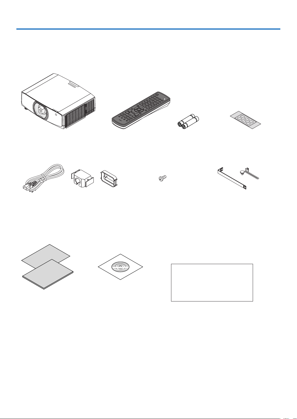
❶ What’s in the Box?
Makesureyourboxcontainseverythinglisted.Ifanypiecesaremissing,contactyourdealer.
Pleasesavetheoriginalboxandpackingmaterialsifyoueverneedtoshipyourprojector.
Projector
Dust cap for lens (24F53241)
* The projector is shipped without
a lens. For the types of lens and
throw distances, see page 162.
Remote control
(7N901081)
AA alkaline batteries
(x2)
Input selection char-
acter sticker
Power cord
(US: 7N080241)
(EU: 7N080022)
Power cord stopper
(24F53221/24F53231)
For the preventive mea-
sure from dropping off
the power cord.
Lens theft prevention screw
(24V00941)
This screw makes it difficult to
remove the lens mounted on
the projector. (→ page 142)
Straps (for preventing the lamp
cover and the lter cover from fall-
ing down) (24F54161, 24F54151)
Attaching the straps to the lamp
cover and the lter cover prevents
them from falling when the projec-
tor is suspended from the ceiling.
For North America only
Limited warranty
For customers in Europe:
You will nd our current valid Guar-
antee Policy on our Web Site:
www.nec-display-solutions.com
• ImportantInfomation(ForNorth
America: 7N8N7661)
• QuickSetupGuide(ForNorth
America: 7N8N7672) (For Other
countries than North America:
7N8N7672 and 7N8N7681)
NEC Projector CD-ROM
User’s manual (PDF)
(7N952552)

2
1. Introduction
❷ Introduction to the Projector
Thissectionintroducesyoutoyournewprojectoranddescribesthefeaturesandcontrols.
Congratulations on Your Purchase of the Projector
Thisprojectorisoneoftheverybestprojectorsavailabletoday.Theprojectorenablesyoutoprojectpreciseimages
upto500inchesacross(measureddiagonally)fromyourPCorMaccomputer(desktopornotebook),VCR,Blu-ray
player,ordocumentcamera.
Youcanusetheprojectoronatabletoporcart,youcanusetheprojectortoprojectimagesfrombehindthescreen,
andtheprojectorcanbepermanentlymountedonaceiling*
1
.Theremotecontrolcanbeusedwirelessly.
*
1
Donotattempttomounttheprojectoronaceilingyourself.
Theprojectormustbeinstalledbyqualiedtechniciansinordertoensureproperoperationandreducetherisk
of bodily injury.
Inaddition,theceilingmustbestrongenoughtosupporttheprojectorandtheinstallationmustbeinaccordance
withanylocalbuildingcodes.Pleaseconsultyourdealerformoreinformation.
Installation
• Liquidcrystaltypehighbrightness/highresolutionprojector
Model Brightness Resolution AspectRatio
PA803U 8000lm WUXGA(1920×1200) 16:10
PA723U
7200lm WUXGA(1920×1200) 16:10
PA653U
6500lm WUXGA(1920×1200) 16:10
PA853W
8500lm WXGA(1280×800) 16:10
PA703W
7000lm WXGA(1280×800) 16:10
PA903X
9000lm XGA(1024×768) 4:3
• Widerangeofoptionallensesselectableaccordingtotheplaceofinstallation
Thisprojectorsupportseighttypesofoptionallenses,providingaselectionoflensesadaptedtoavarietyofplaces
of installation and projection methods.
Inaddition,thelensescanbemountedandremovedinonetouch.
Notethatnolensismounteduponshipmentfromthefactory.Pleasepurchaseoptionallensesseparately.
• Motorizedlenscontrolfunctionforeasilyadjustingthepositionoftheprojectedimage
Thepositionoftheprojectedimage(lensshift)canbeadjustedbybuttonseitheronthecontrolpanelontheside
face of the cabinet or the remote control.
• 360°installationangle(tilt-free)
Theprojectorcanbeinstalledatanyangle(360°)however,theprojectorcannotbeinstalledtiltedtotheleftor
right.
• Portraitprojectionispossible
Thisprojectorcanperformportraitprojectionwiththeprojectionscreenturned90°.
Videos
• Widerangeofinput/outputterminals(HDMI,DisplayPort,HDBaseT,etc.)
Theprojectorisequippedwithavarietyofinput/outputterminals:HDMI(input×2),DisplayPort,HDBaseT(input
x1,outputx1),computer(analog),etc.
Theprojector’sHDMIinput,DisplayPortinputterminalsandHDBaseTPortssupportHDCP.
• HDMIandHDBaseTsupportHDCP2.2/1.4
• DisplayPortsupportsHDCP1.4

3
1. Introduction
• Simultaneousdisplayof2images(PIP/PICTUREBYPICTURE)
Twoimagescanbeprojectedsimultaneouslywithasingleprojector.
Therearetwotypesoflayoutsforthetwoimages:“picture-in-picture”inwhichasub-pictureisdisplayedonthe
mainpicture,and“picture-by-picture”inwhichthemainandsubpicturesaredisplayednexttoeachother.
• Multi-screenprojectionusingmultipleprojectors
ThisprojetorequipstheHDBaseTIN/EthernetandHDBaseTOUT/Ethernetports.Multipleprojectorsinsame
brightnessandresolutionuptofourunitscanbeconnetedinadaisychainbyaLAN*
1
cable via these terminals
withoutavideocable.Ahighqualitypictureisachievedbydividingandprojectinghighresolutionvideosamong
the various projectors.
Furthermore,theboundariesofthescreensaresmoothedusinganedgeblendingfunction.
*
1
UseacommerciallyavailableCAT5eSTPcableoroneinahigherspecication.
• Seamlessswitchfunctionforsmootherscreenchangeswhenswitchingthesignal
Whentheinputconnectorisswitched,theimagedisplayedbeforeswitchingisheldsothatthatthenewimagecan
beswitchedtowithoutabreakduetoabsenceofasignal.
• SupportsHDMI3Dformat
Thisprojectorcanbeusedtowatchvideosin3Dusingcommercially-availableactiveshutter-type3Deyewearand
3DemittersthatsupportXpand3D.
Network
• SupportswiredLAN
EquipstheLANandHDBaseT/Ethernet(RJ-45)ports.UtilizingawiredLANconnectedwiththeseports,itenables
to control the projector by a computer.
• CRESTRONROOMVIEWandExtronXTPcompatibility
Theprojectorsupports CRESTRON ROOMVIEWand ExtronXTP,allowingmultipledevicesconnectedin the
networktobemanagedandcontrolledfromacomputerMoreover,itenablestooutputandcontrolimageviaan
ExtronXTPtransmitterconnectedwiththeprojector..
• Convenientutilitysoftware(UserSupportware)providedasstandard
Thisprojectorsupportsourutilitysoftware(NaViSetAdministrator2,VirtualRemoteTool,etc.).
NaViSetAdministrator2helpsyoucontroltheprojectorbyacomputerviawiredLANconnection.
VirtualRemoteToolhelpsyouperformoperationsbyavirtualremotecontrolsuchasprojector'spoweronoroff
andsignalselectionviawiredLANconnection.Moreover,ithasfunctiontosendanimagetotheprojectorand
registeritasthelogodata.
Pleasevisitourwebsitefordownloadingeachsoftware.
URL:http://www.nec-display.com/dl/en/index.html
Energy-saving
• Energy-savingdesignwithastandbypowerconsumptionof0.15W(100-130VAC)/0.21W(200-240VAC)
Whentheon-screenmenu’sstandbymodeissetto“NORMAL”,thepowerconsumptioninthestandbymodeac-
tivatingthePowerManagementis0.15W(100-130VAC)/0.21W(200-240VAC)and0.11W(100-130VAC)/
0.16W(200-240VAC)whenLANisineffective.
• “Ecomode”forlowpowerconsumptionand“CarbonMeter”display
The projector is equipped with an “eco mode” for reducingpower consumption during use. Furthermore, the
power-savingeffectwhentheecomodeissetisconvertedintotheamountofreductionsofCO
2
emissions and
thisisindicatedontheconrmationmessagedisplayedwhenthepoweristurnedoffandat“Information”onthe
on-screenmenu(CARBONMETER).

4
1. Introduction
Maintenance
• Maximumreplacementtimeforthelampis5000hoursandforthelteris10000hours.
Whenusedintheecomode,thelampreplacementtime*isextendedtoamaximumof5000hours.
*Thistimeisnotguaranteed.
Atthesametime,themaximumusagetimeforthelteris10000hours.**
**Itisvarydependingontheprojectorinstallationcircumstances.
* Actualmenusmaybedifferentfromthemenuimagesinthisuser’smanual.
5
1. Introduction
About this user’s manual
Thefastestwaytogetstartedistotakeyourtimeanddoeverythingrightthersttime.Takeafewminutesnowto
reviewtheuser’smanual.Thismaysaveyoutimelateron.Atthebeginningofeachsectionofthemanualyou’llnd
anoverview.Ifthesectiondoesn’tapply,youcanskipit.
Notation by Resolution
Theseindicatethedescriptionsofthemodelgroupsaccordingtotheresolutionoftheliquidcrystalpanels.
WUXGAType
ApplicabletomodelsPA803U/PA723U/PA653U.
WXGAType
ApplicabletomodelsPA853W/PA703W.
XGAType
ApplicabletomodelsPA903X.
*Thedescriptionappliestoallmodelsifthetypenameisnotindicated.
How to Differentiate the Model Group
P A 8 0 3 U
“U”referstoaWUXGAtype.
“W”referstoaWXGAtype.
“X”referstoaXGAtype.
ModelNameSymbol
Example:PA803U
“NP-”isnotindicatedontopofthecabinet.
6
1. Introduction
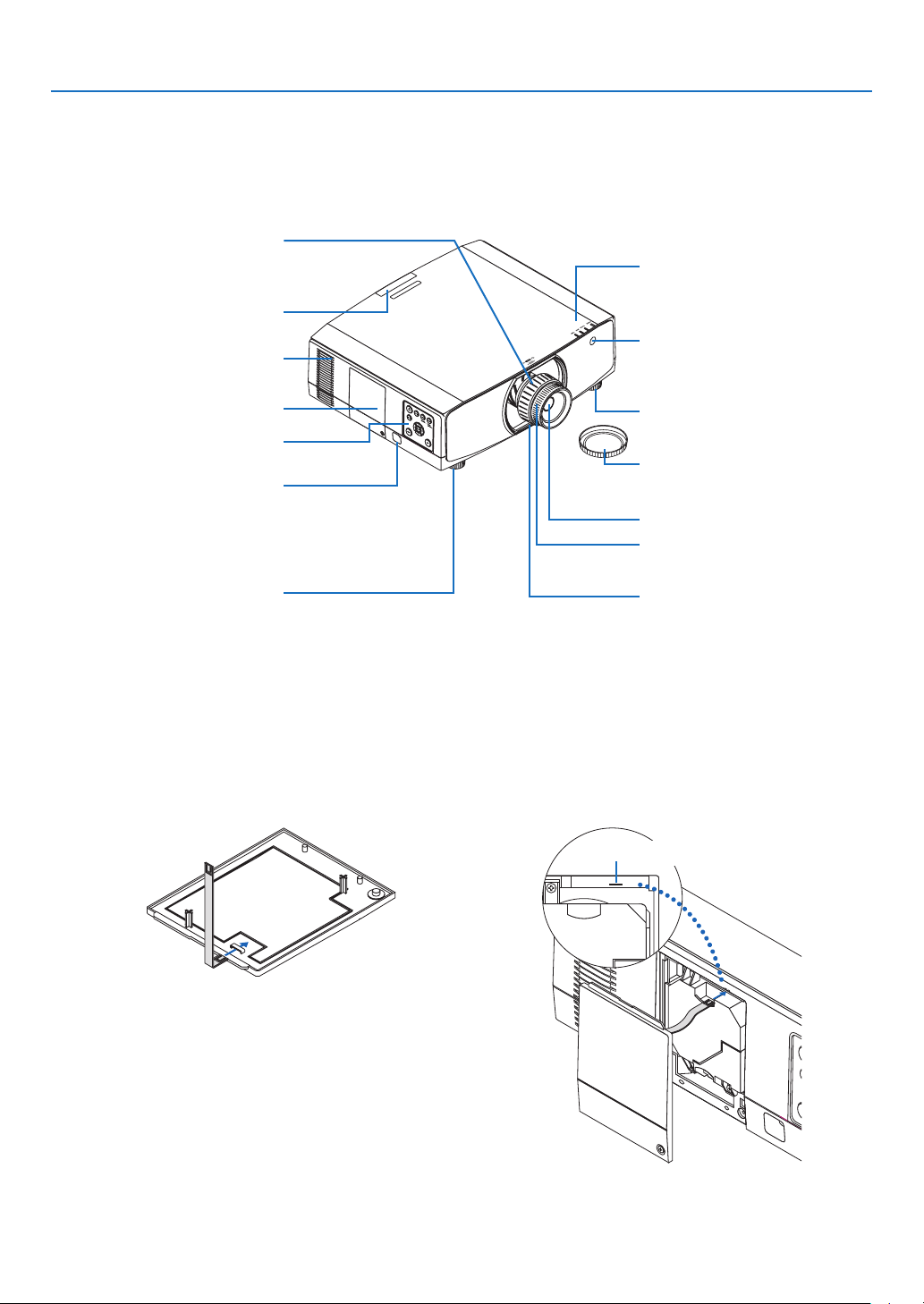
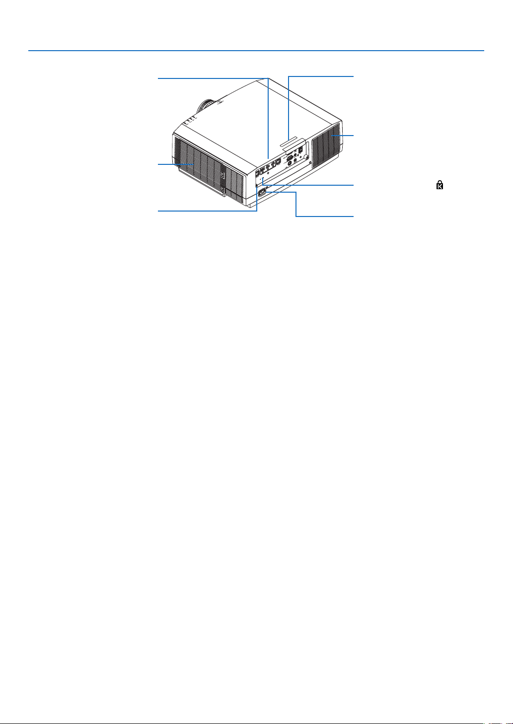
❸ Part Names of the Projector
Front/Top
Thelensissoldseparately.ThedescriptionbelowisforwhentheNP13ZLlensismounted.
Controls
(→ page 9)
Lens
Remote Sensor (located on the
front and the rear)
(→ page 13)
Remote Sensor
(→ page 13)
Zoom Lever/Zoom Ring (→ page
28)
Lens Cap
(The optional lens is shipped with
the lens cap.)
Focus Ring
(→ page 23)
Adjustable Tilt Foot
(→ page 29)
Indicator Section
(→ page 9)
Lens Release Button
(→ page 142)
Adjustable Tilt Foot
(→ page 29)
Exhaust vent
Heated air is exhausted from here.
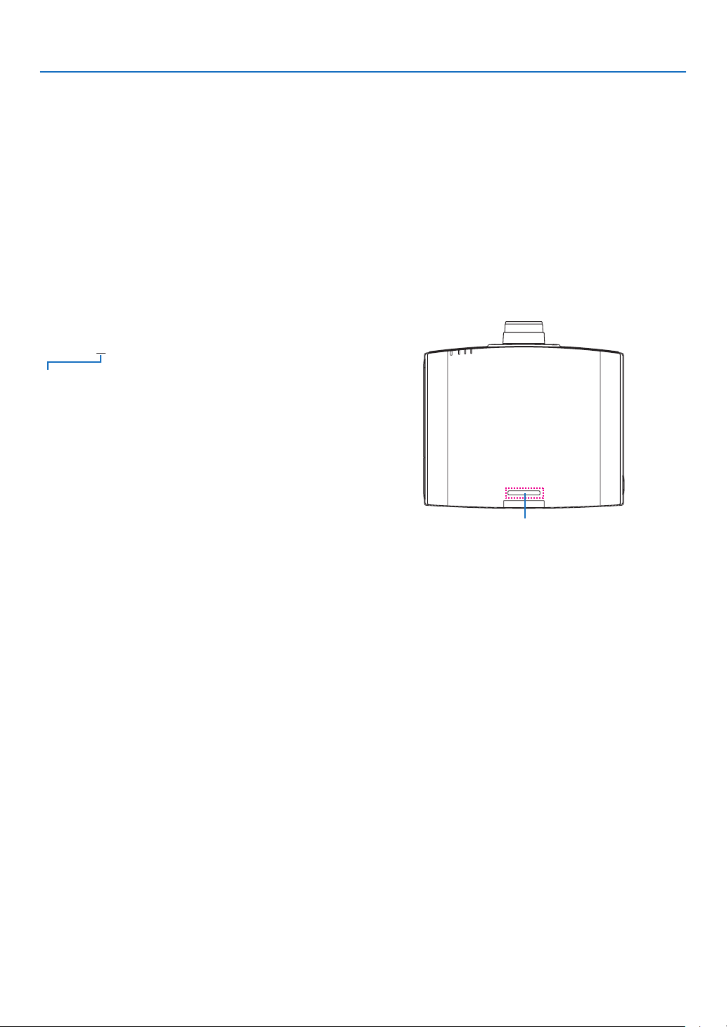
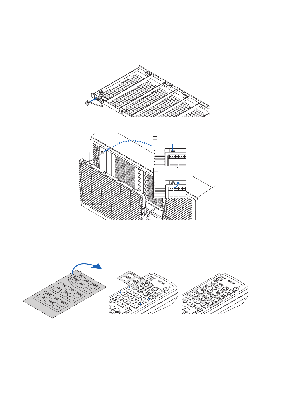
Mounting the strap
Beforestartingtouse,mountthestrapstothelampcoverandtheltercoverforpreventingthemfromdroppingdown.
Lamp cover
Preparation:Removethelampcoverfromtheprojector.
Refertotheclause“Replacingthelamp”onpage156 about the lamp cover installation.
1. Insert the L-shaped part of the lamp cover strap (flat resinoid strap) to the protruded section on the rear
face of the lamp cover as the below illustration.
Hole for xing the strap
2. Insert the opposite side of the lamp cover strap to the hole on the projector body.
Lamp Cover (→ page 156)
Security Bar
Attach an anti-theft device.
The security bar accepts security
wires or chains up to 0.18 inch/4.6
mm in diameter.
7
1. Introduction
Filter cover
Preparation:Removetheltercoverfromtheprojector.
Refertotheclause“Replacingthelter”onpage160abouttheltercoverinstallation.
1. Insert the round protrusion at the filter cover strap end (resinoid strap) to the hole on the filter cover.
2. Insert the square protrusion at the opposite end of the filter cover strap to the hole on the projector body
and rotate the strap 90°for fixation. It becomes easier to fix the strap if you remove the filter once.
Hole for xing the strap
Rotate the strap 90°
How to paste the input selection character sticker of the remote control
• PeeloffthecoverofthestickerandalignthestickerholeswithButtons1to6beforepasting.
• Pleasetakecarenottoletthestickercontactthebuttonswhenpasting.
• Theexplanationsandillustrationsinthismanualareprovidedwiththestickerpasted.
8
1. Introduction
Terminals
(→ page 10)
Rear
Remote Sensor (located on the
front and the rear)
(→ page 13)
AC IN Terminal
Connect the supplied power cord’s
three-pin plug here, and plug the
other end into an active wall outlet.
(→ page 15)
* ThissecurityslotsupportstheMicroSaver
®
SecuritySystem.
Built-in Security Slot ( )*
Cable cover connection
(right and left)
Screw holes and grooves for the
optional cable cover
(→ page 176)
Intake vent / Filter
(→ page 153, 160)
Exhaust vent
Heated air is exhausted from here.
9
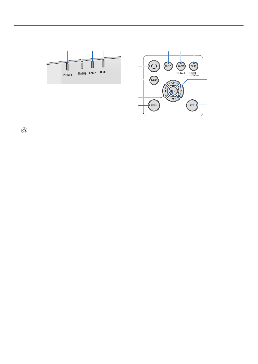
1. Introduction
Controls/Indicator Panel
2 3 4 5
10
7
8
1
6
9
11 12 13
1. (POWER)Button
(→page17,31)
2. POWER Indicator
(→page16,17,31,180,183)
3. STATUS Indicator
(→page180)
4. LAMPIndicator
(→page156,180)
5. TEMP.Indicator
(→page36,180)
6. INPUT Button
(→page19)
7. MENU Button
(→page76)
8. ▲▼◀▶/VolumeButtons◀▶
(→page30,76)
9. ENTER Button
(→page76)
10.EXITButton
(→page76)
11. FOCUS Button
(→page26)
12. ZOOM/L-CALIB. Button
(→page28)
13. SHIFT/HOME POSITION Button
(→page22)
10
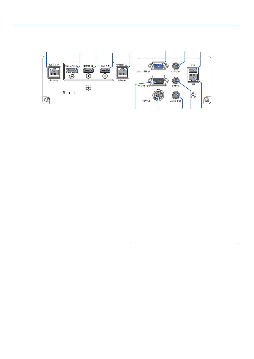
1. Introduction
Terminals
2 73 1
4
5
811
12
13 10
6
9
1. HDMI1INTerminal(TypeA)
(→page144,145,147)
2. HDMI2INTerminal(TypeA)
(→page144,145,147)
3. DisplayPort IN Terminal
(→page144)
4. COMPUTERIN/ComponentInputTerminal(Mini
D-Sub15Pin)
(→page143,146)
5. COMPUTERAUDIOINMiniJack(StereoMini)
(→page143,145)
6. HDBaseTIN/EthernetPort(RJ-45)
(→page148,149)
7. HDBaseT OUT/EthernetPort(RJ-45)
(→page63,149)
8. AUDIOOUTMiniJack(StereoMini)
(→page143,145,147)
9. USB-APort(TypeA)
(→page122)
10. LANPort(RJ-45)
(→page152)
11. 3DSYNCTerminal(MiniDIN3Pin)
(→page46)
12.PCCONTROLPort(D-Sub9Pin)
(→page178)
Use this port to connect a PC or control system.
Thisenablesyoutocontroltheprojectorusingserial
communicationprotocol.Ifyouarewritingyourown
program,typicalPCcontrolcodesareonpage188.
13.REMOTETerminal(StereoMini)
Use this terminal for wired remote control of the pro-
jectorusingtheNECremotecontrol,RD-465E.
Connectthe projector and our remote control,RD-
465E,usinga commercially availablewiredremote
control cable.
NOTE:
• WhenaremotecontrolcableisconnectedtotheREMOTE
terminal, infrared remote control operations cannot be per-
formed.
• When [HDBaseT]is selected in the[REMOTE SENSOR]
and the projector is connected to a commercially-available
transmissiondevicethatsupportsHDBaseT,remotecontrol
operations in infra-red cannot be carried out if transmission
of remote control signals has been set up in the transmission
device.However,remotecontrolusinginfraredrayscanbe
carried out when the power supply of the transmission device
is switched off.
11
1. Introduction
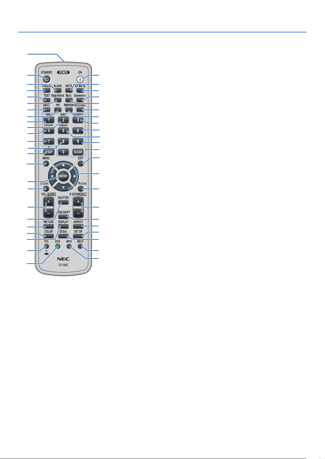
❹ Part Names of the Remote Control
9. Edge Blend. Button
(→page71)
10. Multi. Button
(→page109)
11. Geometric. Button
(→page38,103)
12. INPUT Button
(→page19)
13. PIP Button
(→page67)
14.PBP/POPButton
(→page67)
15.AUTOADJ.Button
(→page30)
16.1(HDMI1)Button
(→page19)
17. 2(HDMI2)Button
(→page19)
18.3(DisplayPort)Button
(→page19)
19.4(Computer)Button
(→page19)
20.5(HDBaseT)Button
(→page19)
21. 6 Button
(not available on this series of
projectors)
22. 7 Button
(not available on this series of
projectors)
23. 8 Button
(not available on this series of
projectors)
24.9Button
(not available on this series of
projectors)
25.IDSETButton
(→page123)
26. Numeric Keypad Button/
CLEAR Button
(→page123)
27. MENU Button
(→page76)
1. Infrared Transmitter
(→page13)
2. POWER ON Button
(→page17)
3. STANDBY Button
(→page31)
4. FREEZEButton
(→page35)
5. BLANKButton
(→page33)
6. MUTE Button
(→page33)
7. AV-MUTEButton
(→page33)
8. TEST Button
(→page84)
28.EXITButton
(→page76)
29. ▲▼◀▶ Button
(→page76)
30. ENTER Button
(→page76)
31. L-CLICK Button*
32. R-CLICK Button*
33.VOL./FOCUS(+)(−)Button
(→page26)
(Works only when NP40ZL,
NP41ZL,orNP43ZLismounted)
34.D-ZOOM/ZOOM(+)(−)Button
(→page35)
(Works only when NP40ZL,
NP41ZL,orNP43ZLismounted)
35.SHUTTERButton
(not available on this series of
projectors)
36. LENS SHIFT Button
(→page22)
37. PICTURE Button
(→page88)
38. DISPLAY Button
(→page101)
39. ASPECT Button
(→page94)
40.COLORButton
(→page90)
41.3DSet.Button
(→page46)
42.SETUPButton
(→page111)
43.CTLButton
(→page26,28,34)
44.ECOButton
(→page36)
45.INFOButton
(→page137)
46.HELPButton
(→page136)
1
3
5
4
8
9
12
13
2
6
7
11
10
15
14
16
19
22
25
23
17
27
31
33
35
30
21
28
29
20
32
24
26
18
34
36
43
44
46
45
37
40
38
42
41
39
* The▲▼◀▶,L-CLICKandR-CLICKbuttonsworkonlywhenaUSBcableisconnectedwithyourcomputer.
12
1. Introduction
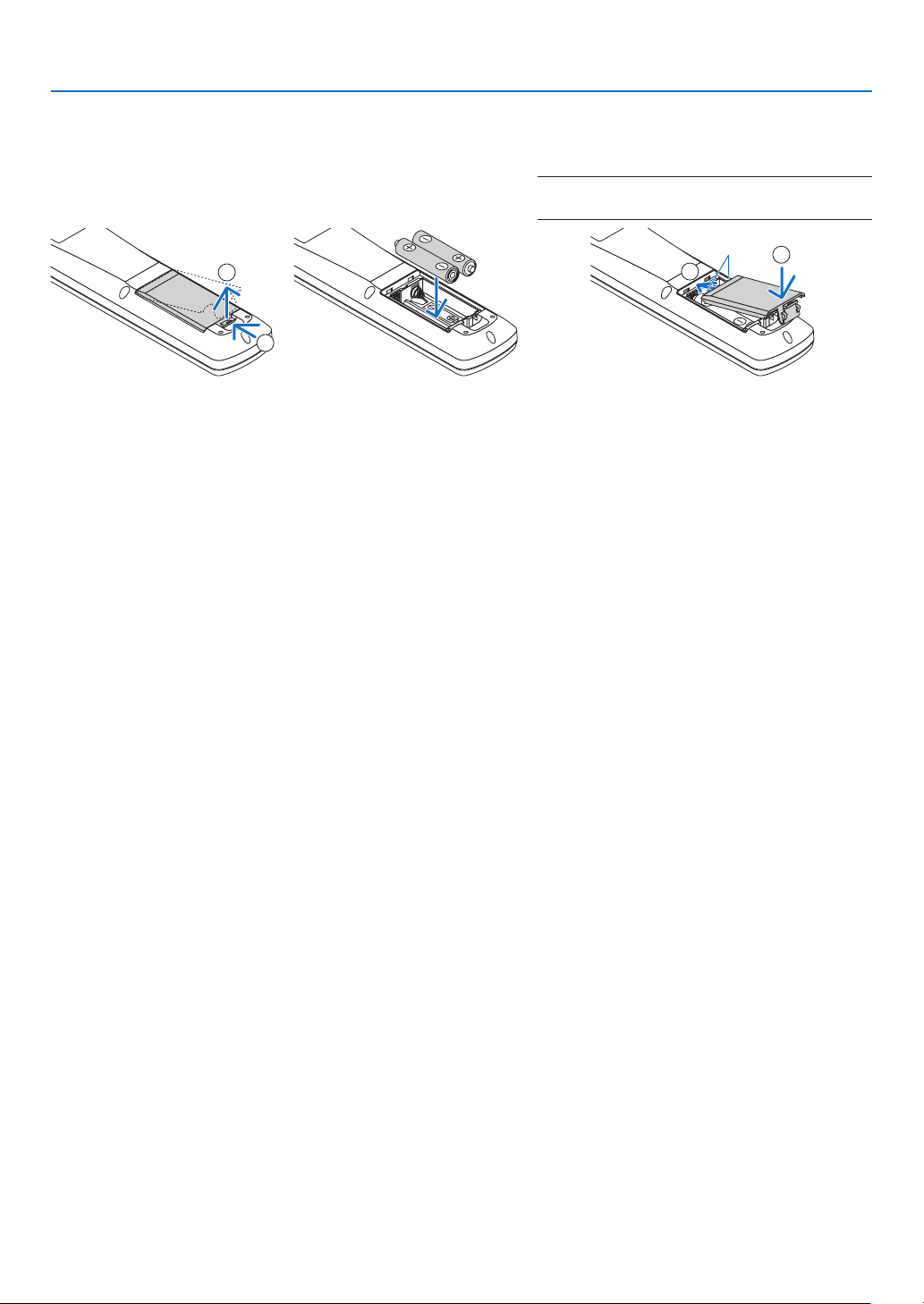
Battery Installation
1. Press the catch and remove
the battery cover.
2. Install new ones (AA). En-
sure that you have the bat-
teries’polarity(+/−)aligned
correctly.
3. Slipthecoverbackoverthebatteriesuntil
it snaps into place.
NOTE:Donotmixdifferenttypesofbatteriesornew
and old batteries.
1
2
1
2
Remote Control Precautions
• Handletheremotecontrolcarefully.
• Iftheremotecontrolgetswet,wipeitdryimmediately.
• Avoidexcessiveheatandhumidity.
• Donotshort,heat,ortakeapartbatteries.
• Donotthrowbatteriesintore.
• Ifyouwillnotbeusingtheremotecontrolforalongtime,removethebatteries.
• Ensurethatyouhavethebatteries’polarity(+/−)alignedcorrectly.
• Donotusenewandoldbatteriestogether,orusedifferenttypesofbatteriestogether.
• Disposeofusedbatteriesaccordingtoyourlocalregulations.
• Replacetwobatteriesatthesametimewiththequitesameonesthathasbeeninstalledintheremotecontrolor
AAsizedalkalisbatterythatisconformedtoIEC60086-5.
13
1. Introduction
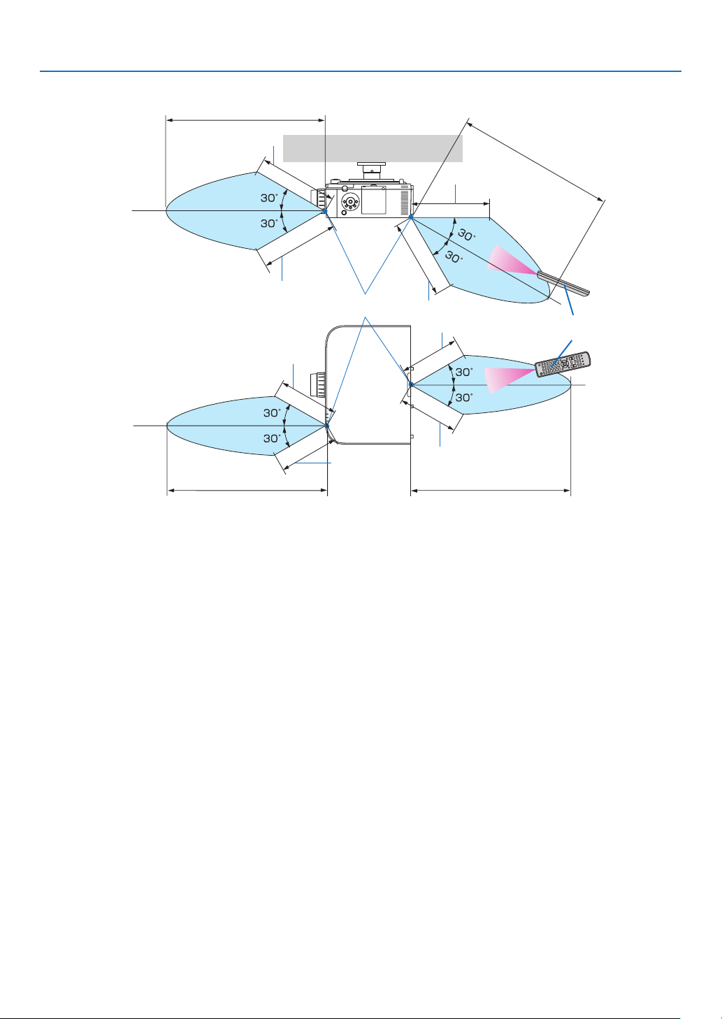
Operating Range for Wireless Remote Control
40 m/1575 inch
40 m/1575 inch
Remote control
Remote sensor on projector cabinet
40 m/1575 inch
40 m/1575 inch
20 m/787 inch
20 m/787 inch
20 m/787 inch
20 m/787 inch
15 m/591 inch
15 m/591 inch
15 m/591 inch
15 m/591 inch
• Theinfraredsignaloperatesbyline-of-sightuptoadistanceofabovemetersandwithina60-degreeangleofthe
remote sensor on the projector cabinet.
• Theprojectorwillnotrespondifthereareobjectsbetweentheremotecontrolandthesensor,orifstronglightfalls
onthesensor.Weakbatterieswillalsopreventtheremotecontrolfromproperlyoperatingtheprojector.

14
Thissectiondescribeshowtoturnontheprojectorandtoprojectapictureontothescreen.
❶ Flow of Projecting an Image
Step 1
• Connectingyourcomputer/Connectingthepowercord(→page15)
Step 2
• Turningontheprojector(→page17)
Step 3
• Selectingasource(→page19)
Step 4
• Adjustingthepicturesizeandposition(→page21)
• Correctingkeystonedistortion[CORNERSTONE](→page38, 103)
Step 5
• Adjustingapictureandsound
- Optimizing a computer signal automatically (→ page 30)
- Turning up or down volume (→ page 30)
Step6
• Makingapresentation
Step 7
• Turningofftheprojector(→page31)
Step 8
• Afteruse(→page32)
2. Projecting an Image (Basic Operation)
15
2. Projecting an Image (Basic Operation)
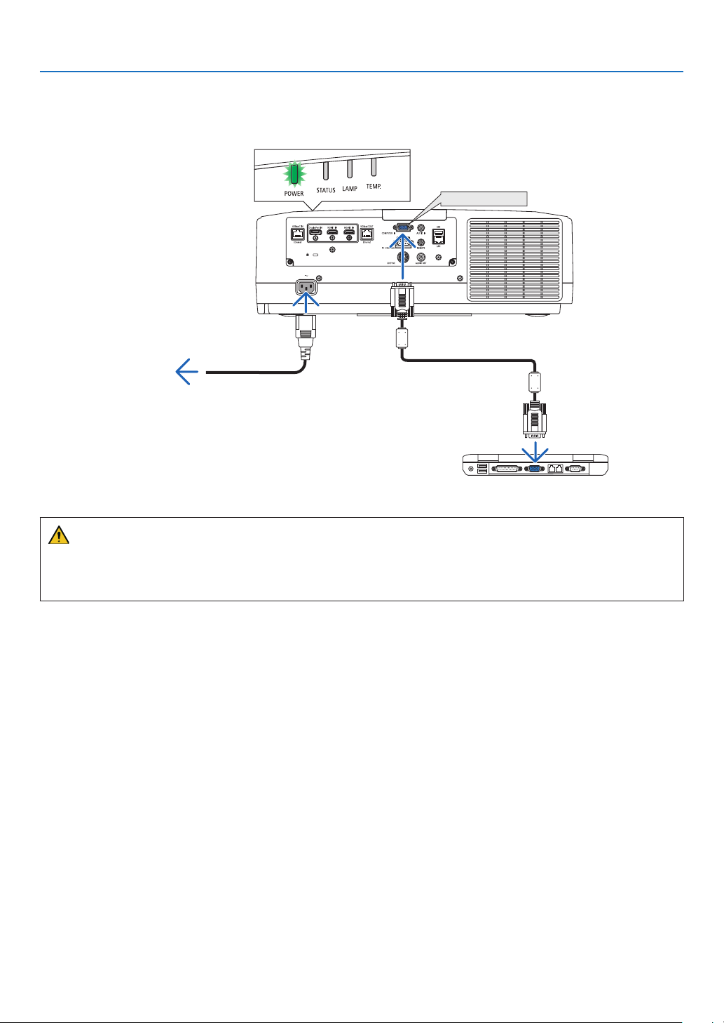
❷ Connecting Your Computer/Connecting the Power Cord
1. Connectyourcomputertotheprojector.
This section will show you a basic connection to a computer. For information about other connections, see “(2)
Making Connections” on page 143.
Connect the display output terminal (mini D-sub 15 pin) on the computer to the computer video input terminal
on the projector with a commercially-available computer cable (with ferrite core) and then turn the knobs of the
connectors to secure them.
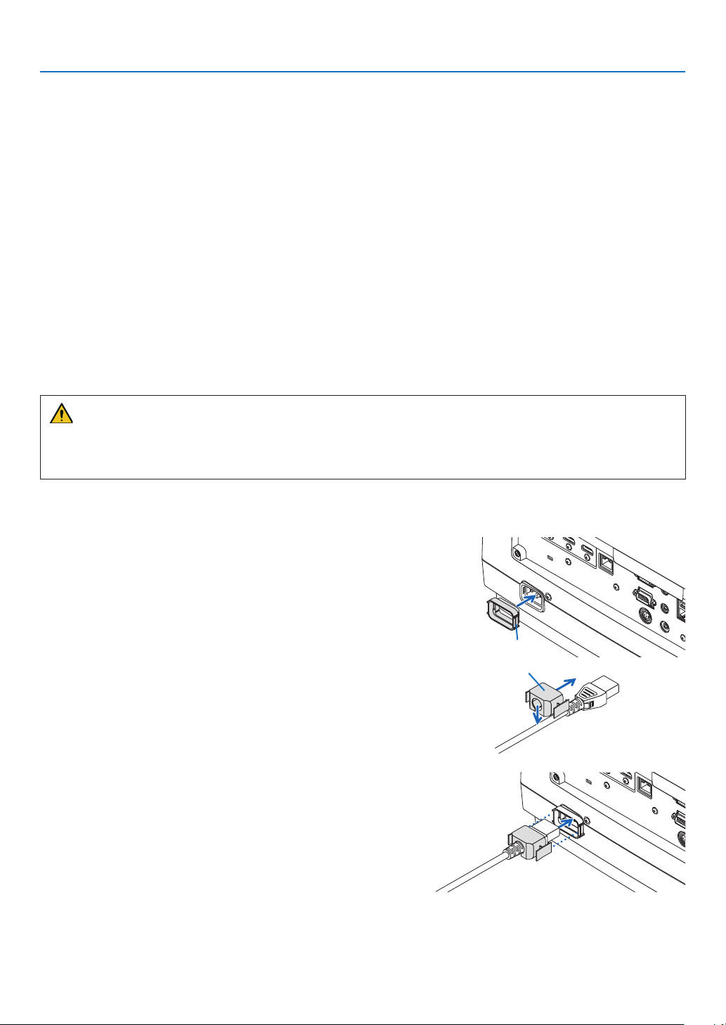
2. Connectthesuppliedpowercordtotheprojector.
First connect the supplied power cord’s three-pin plug to the AC IN terminal of the projector, and then connect
another plug of the supplied power cord directly in the wall outlet. Do not use any plug converter.
Using the power cord stopper
TopreventthepowercordfromaccidentlyremovingfromtheACINoftheprojector,usethepowercordstopper.
CAUTION
• Topreventthepowercordfromcomingloose,makesurethatalltheprongsofthepowercordplugarefullyin-
sertedintotheACINterminaloftheprojectorbeforeusingthepowercordstopper.Aloosecontactofthepower
cordmaycauseareorelectricshock.
Thepowercordstopperisconsistedfromthepart(A)thatshouldbeinstalledontheprojectorandthepart(B)that
should be installed on the power cord.
1. Fixthepart(A)totheACINterminalontheprojector
cabinet.
Part (A)
2. Fixthepart(B)tothepowercord.
Part (B)
3. InsertthepowercordplugtotheACINterminaluntil
the power cord stopper is fastened completely and
clicksoundisheard.
16
2. Projecting an Image (Basic Operation)
Upon connecting the power cable, the POWER indicator of the projector will light in green. If there are no input
signals, the device will go into the standby state.
(In the state, standby mode is NORMAL.) (→ page 183)
COMPUTER IN
Make sure that the prongs are fully inserted into
both the AC IN and the wall outlet.
To wall outlet
Computer cable (with ferrite core)
(sold commercially)
CAUTION:
PartsoftheprojectormaybecometemporarilyheatediftheprojectoristurnedoffwiththePOWERbuttonorifthe
ACpowersupplyisdisconnectedduringnormalprojectoroperation.
Usecautionwhenpickinguptheprojector.
17
2. Projecting an Image (Basic Operation)
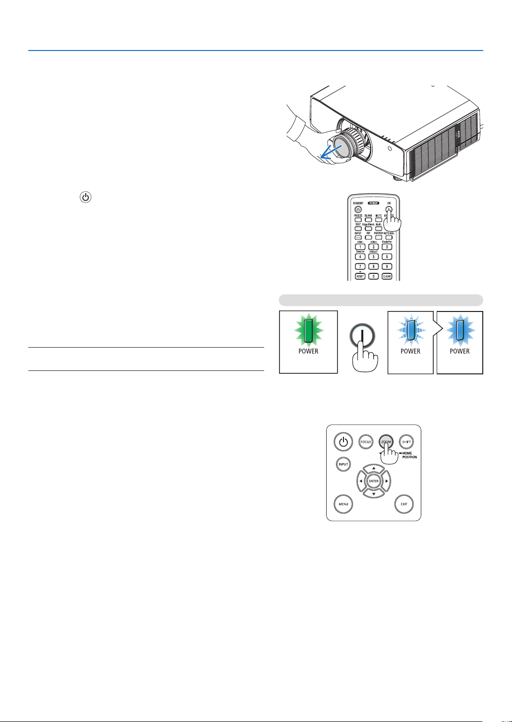
❸ Turning on the Projector
1. Removethelenscap.
2. Press the (POWER)buttonontheprojectorcabinet
orthePOWERONbuttonontheremotecontrol.
The POWER indicator lit in green will start to blink in blue.
After that, the image will be projected onto the screen.
TIP:
• Whenthemessage“PROJECTORISLOCKED!ENTERYOUR
PASSWORD.” is displayed, it means thatthe [SECURITY]
feature is turned on. (→ page 43)
• Whenthe ECO message isdisplayed, it meansthat [ON] is
selectedfor[ECOMESSAGE].(→ page 112)
After you turn on your projector, ensure that the computer
or video source is turned on.
NOTE: A blue screen (blue background) is displayed when no signal
is being input (by factory default menu settings).
Sleep state Blinking Power On
Blinking in green
Blinking blue
light
Steady blue
light
(→page180)
Performing Lens Calibration
Aftermountingtheseparatelyavailablelensunitorreplacing
alensunit,perform[LENSCALIBRATION]byholdingtopress
ZOOM/L-CALIB.buttononthecabinetovertwoseconds.
Calibration corrects the adjustable zoom, shift, and focus
range.Ifcalibrationisnotperformed,youmaynotbeableto
getthebestfocusandzoomevenifyouadjustthefocusand
zoomforthelens.
18
2. Projecting an Image (Basic Operation)
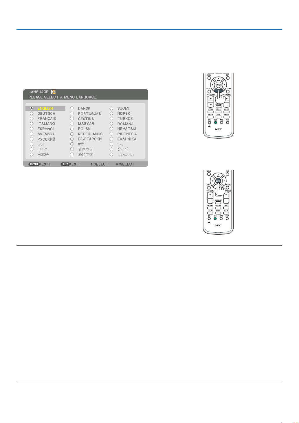
Note on Startup screen (Menu Language Select screen)
Whenyourstturnontheprojector,youwillgettheStartupmenu.Thismenugivesyoutheopportunitytoselectone
ofthe29menulanguages.
To select a menu language, follow these steps:
1. Use the ▲, ▼, ◀ or ▶ button to select one of the 30
languagesfromthemenu.
2. PresstheENTERbuttontoexecutetheselection.
After this has been done, you can proceed to the menu
operation.
Ifyouwant,youcanselectthemenulanguagelater.
(→[LANGUAGE]onpage80 and 111)
NOTE:
• Ifthemessage,[PLEASESET"DATEANDTIME".]isshown,pleasesetthecurrentdateandtime.(→ page 122)
• Inthecasethismessageisnotshown,the[DATEANDTIMESETTING]isrecommendedtocomplete.
• Duringprojection,aftershuttingdownthepowersupply(directpoweroff),waitforabout1minuteorlongerbeforeturningon
the power again.
• Keepthelenscapoffthelenswhiletheprojector’spowerison.
If the lens cap is on, it could be warped due to high temperature.
• Ifoneofthefollowingthingshappens,theprojectorwillnotturnon.
- If the internal temperature of the projector is too high, the projector detects abnormal high temperature. In this condition the
projectorwillnotturnontoprotecttheinternalsystem.Ifthishappens,waitfortheprojector’sinternalcomponentstocool
down.
- IftheSTATUSindicatorlightsorangewiththepowerbuttonpressed,itmeansthatthe[CONTROLPANELLOCK]isturnedon.
Cancelthelockbyturningitoff.(→ page 122)
- Ifthelampfailstolight,andifthePOWERindicatorblinksinredandtheLAMPindicatorlightsinred,waitafullminuteand
then turn on the power.
• WhilethePOWERindicatorisblinkingblueinshortcycles,thepowercannotbeturnedoffbyusingthepowerbutton.
• Immediatelyafterturningontheprojector,screenickermayoccur.Thisisnormal.Wait3to5minutesuntilthelamplightingis
stabilized.
• Whentheprojectoristurnedon,itmaytakesometimebeforethelamplightbecomesbright.
• Ifyouturnontheprojectorimmediatelyafterthelampisturnedofforwhenthetemperatureishigh,thefansrunwithoutdisplay-
ing an image for some time and then the projector will display the image.
19
2. Projecting an Image (Basic Operation)
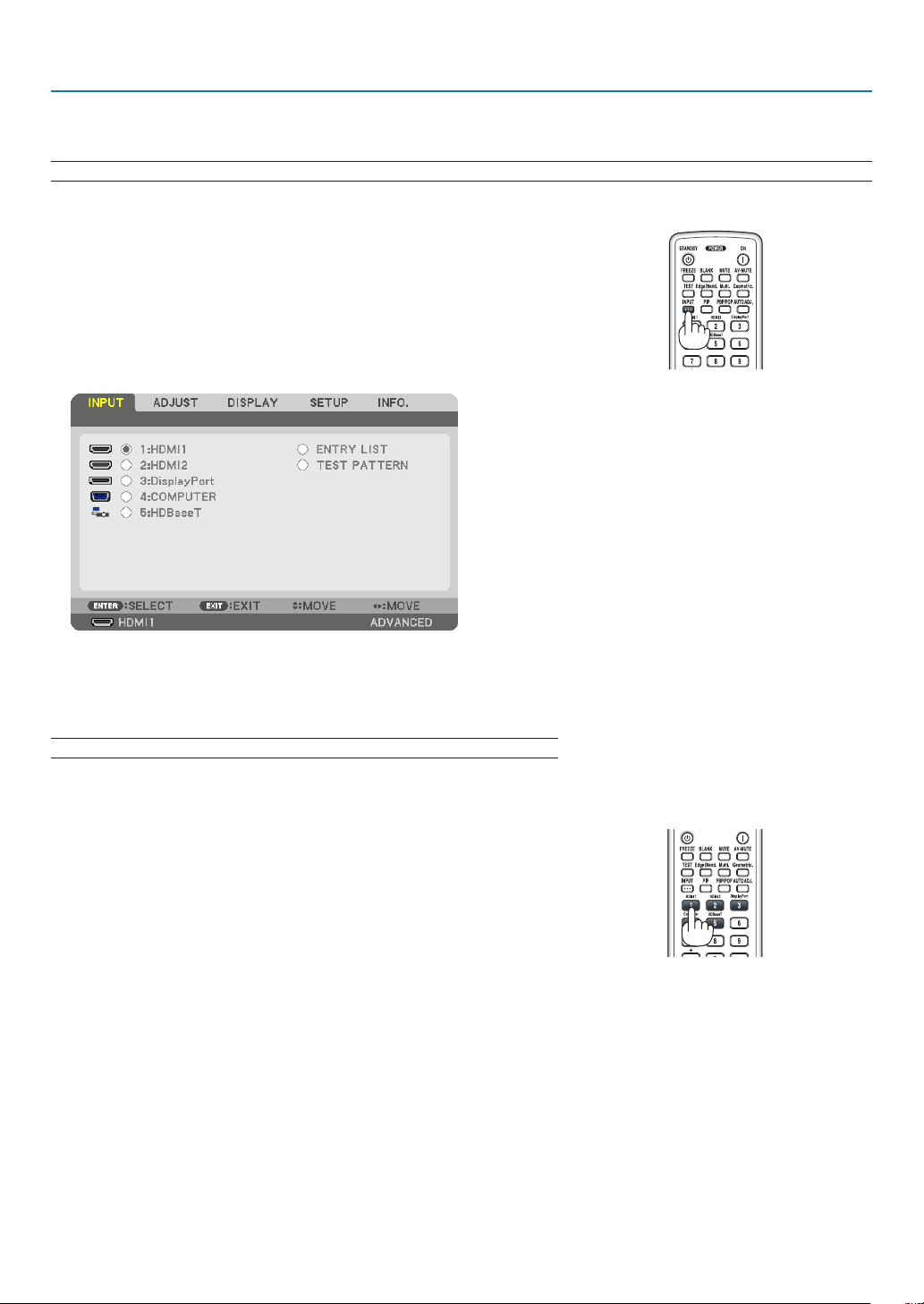
❹ Selecting a Source
Selecting the computer or video source
NOTE: Turn on the computer or video source equipment connected to the projector.
Detecting the Signal Automatically
PresstheINPUTbuttonfor1secondorlonger.Theprojectorwillsearch
fortheavailableinputsourceanddisplayit.Theinputsourcewillchange
as follows:
HDMI1→HDMI2→DisplayPort→COMUPTER→HDBaseT→HDMI1
→ …
• Pressitbrieytodisplaythe[INPUT]screen.
Press the ▼/▲buttonstomatchthetargetinputterminalandthenpress
theENTERbuttontoswitchtheinput.Todeletethemenudisplayin
the[INPUT]screen,presstheMENUorEXITbutton.
TIP: If no input signal is present, the input will be skipped.
Using the Remote Control
Pressanyoneofthe1/HDMI1,2/HDMI2,3/DisplayPort,4/Computer,
or5/HDBaseTbutton.
20
2. Projecting an Image (Basic Operation)
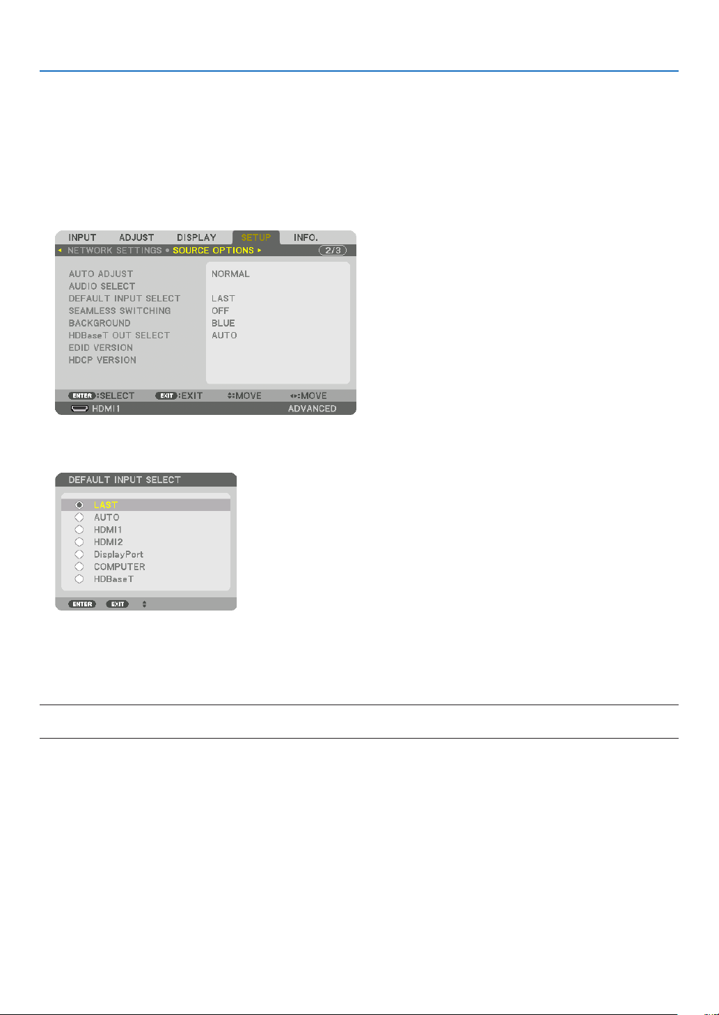
Selecting Default Source
Youcansetasourceasthedefaultsourcesothatitwillbedisplayedeachtimetheprojectoristurnedon.
1. Press the MENU button.
The menu will be displayed.
2. Press the ▶buttontoselect[SETUP]andpressthe▼buttonortheENTERbuttontoselect[BASIC].
3. Press the ▶buttontoselect[SOURCEOPTIONS]andpressthe▼buttonortheENTERbutton.
4. Press the ▼buttonthreetimestoselect[DEFAULTINPUTSELECT]andpresstheENTERbutton.
The [DEFAULT INPUT SELECT] screen will be displayed.
(→ page 130)
5. Selectasourceasthedefaultsource,andpresstheENTERbutton.
6. PresstheEXITbuttonafewtimestoclosethemenu.
7. Restarttheprojector.
The source you selected in step 5 will be projected.
NOTE:Evenwhen[AUTO]isturnedon,the[HDBaseT]willnotbeautomaticallyselected.Tosetyournetworkasthedefaultsource,
select[HDBaseT].
TIP:
• WhentheprojectorisinStandbymode,applyingacomputersignalfromacomputerconnectedtotheCOMPUTERINinputwill
powerontheprojectorandsimultaneouslyprojectthecomputer’simage.
([AUTOPOWERONSELECT]→ page 132)
• OntheWindows7keyboard,acombinationoftheWindowsandPkeysallowsyoutosetupexternaldisplayeasilyandquickly.
21
2. Projecting an Image (Basic Operation)
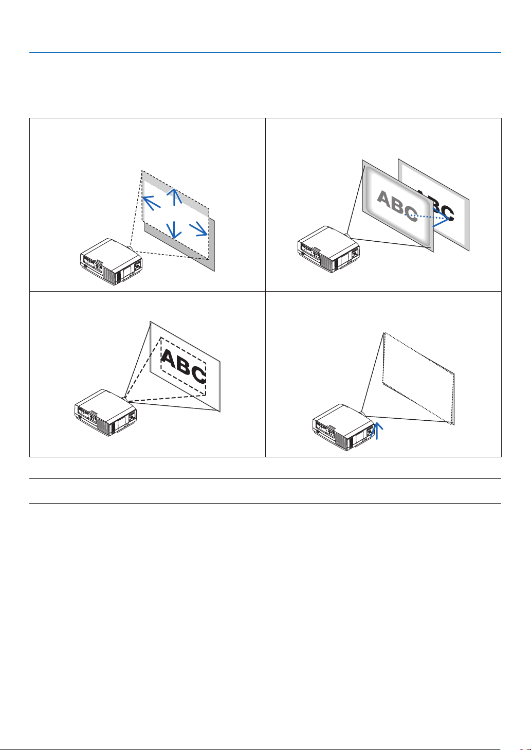
❺ Adjusting the Picture Size and Position
Usethelensshiftdial,theadjustabletiltfootlever,thezoomandthefocusringtoadjustthepicturesizeandposition.
In this chapter drawings and cables are omitted for clarity.
Adjustingtheprojectedimage’sverticalandhorizontal
position
[Lensshift]
(→page22)
Adjustingthefocus
[Focusring]
(→page23)
Finelyadjustingthesizeofanimage
(→page28)
Adjustingtheprojectedimage’sinclination
[Tiltfoot]*¹
(→page29)
NOTE*
1
:Adjusttheprojectedimage’sheightusingthetiltfeetwhenyouwanttoprojecttheimageatapositionhigherthanthelens
shift adjustment range.
22
2. Projecting an Image (Basic Operation)
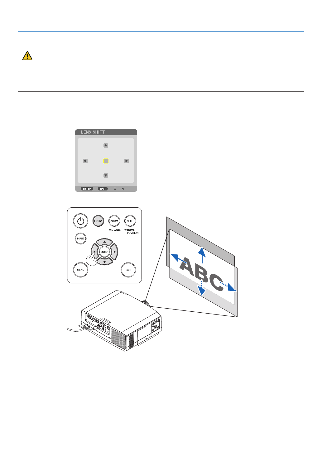
Adjusting the vertical position of a projected image (Lens shift)
CAUTION
• Performtheadjustmentfrombehindorfromthesideoftheprojector.Adjustingfromthefrontcouldexposeyour
eyestostronglightwhichcouldinjurethem.
• Keephandsawayfromthelensmountingportionwhileperformingalensshift.Failuretodosocouldresultin
ngersbeingpinchedbythemovinglens.
1. PresseitherSHIFT/HOMEPOSITIONbuttononthecabinetorLENS
SHIFTBUTTONontheremotecontrol.
The [LENS SHIFT] screen will be displayed.
2. Press the ▼▲◀▶buttonstomovetheprojectedimage.
• Tosetbackthelenstothehomeposition
Press and hold the SHIFT/HOME POSITION button over 2 seconds. The lens mounted on the projector goes
back to the home position. (roughly to the center position)
NOTE:
• Ifthelensisshiftedtothemaximuminthediagonaldirection,thescreenperipheralareawillbedarkorshaded.
• UseNP11FLatthehomeposition.
23
2. Projecting an Image (Basic Operation)
TIP:
• Thediagrambelowshowsthelensshiftadjustmentrange(projectionformat:desk/front)oftheWUXGAtype(excludingthelens
unitNP30ZL).
• RefertoPage167forthelensshiftadjustmentrangeoftheWXGAtype/XGAtypeandforceilinghanging/frontprojection.
100%V
50%V
10%V
100%H
30%H 30%H
10%H 10%H
Height of projected image
Width of projected image
NP803U/PA723U/PA653U
Descriptionofsymbols:Vindicatesvertical(heightoftheprojectedimage),Hindicateshorizontal(widthoftheprojectedimage).
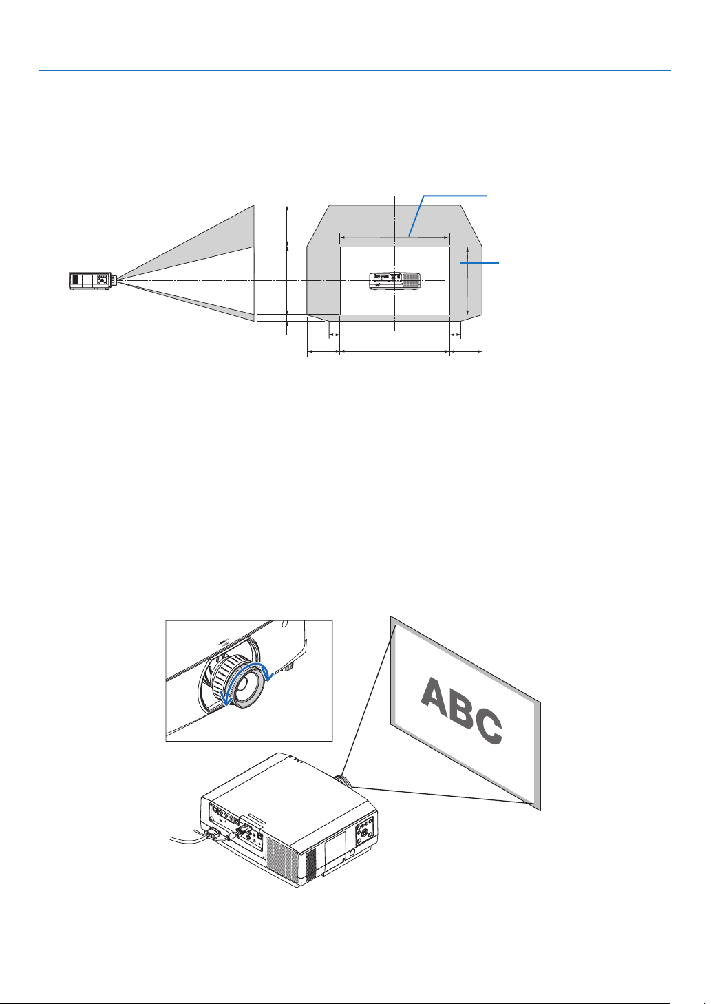
Focus
RecommendtoperformthefocusadjustmentafterleavingtheprojectorunderthestatetheTESTPATTERNhas
beenprojectedforover30minutes.
Pleaserefertopage87intheUser’sManualabouttheTESTPATTERN.
Applicablelens:NP12ZL/NP13ZL/NP14ZL
Usethefocusringtoobtainthebestfocus.
Focus ring
24
2. Projecting an Image (Basic Operation)
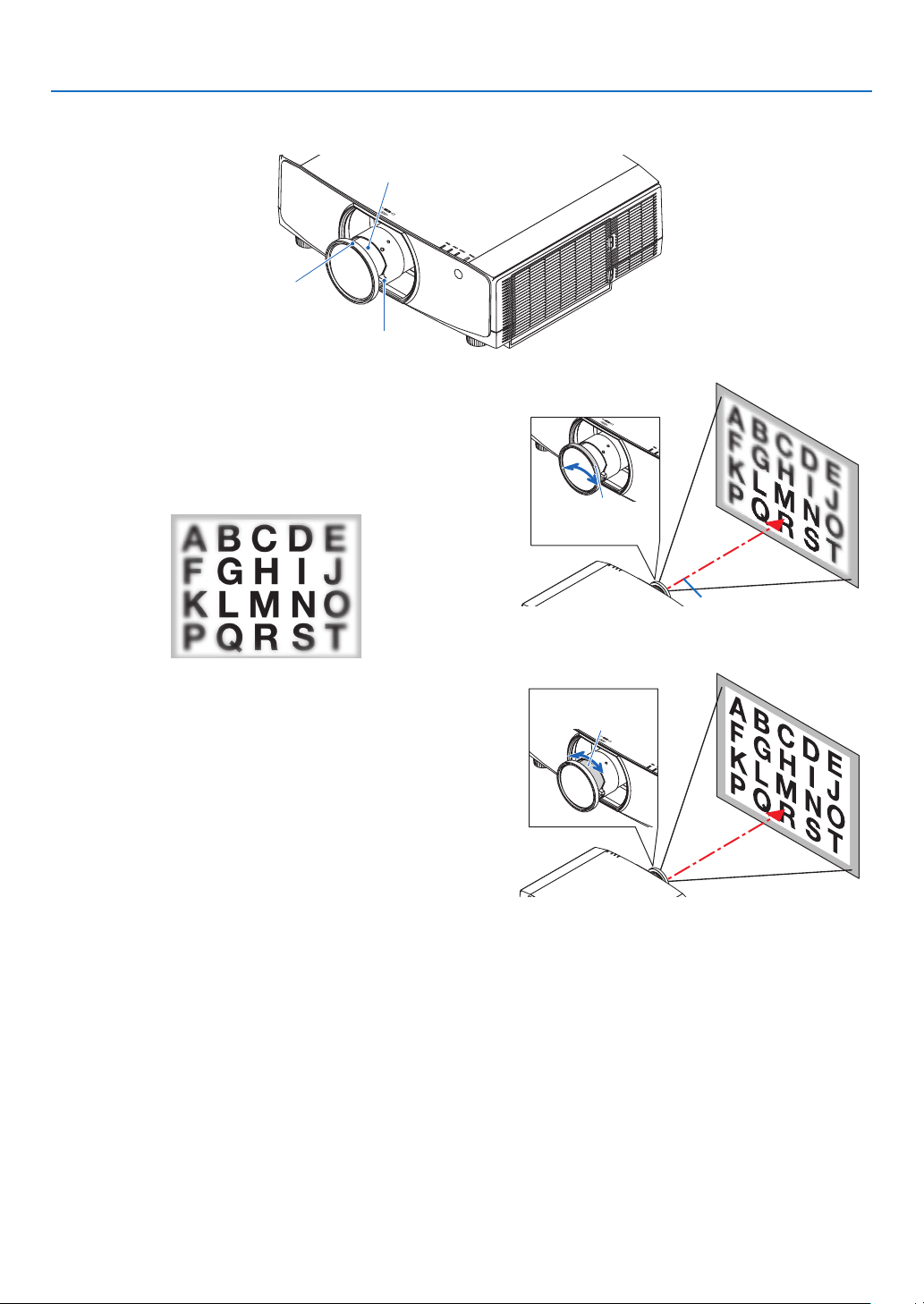
Applicable lens: NP30ZL
TheNP30ZLlensunitalignstheperipheralfocusaroundtheopticalaxis.
Peripheral focus ring
Focus Ring
Zoom Lever
1. Turn the focus ring left and right to align the focus
around the optical axis.
* The diagram shows an example when the lens shift is
moved upward. The bottom of the screen is adjusted.
When the lens is in the center, the center of the screen
is adjusted.
Focus Ring
Optical axis
2. Turntheperipheralfocusringtotheleftandrightto
alignthefocusofthescreenperipheralarea.
At this point, the focus around the optical axis adjusted in
(1) remains unchanged.
Peripheral focus
ring
25
2. Projecting an Image (Basic Operation)
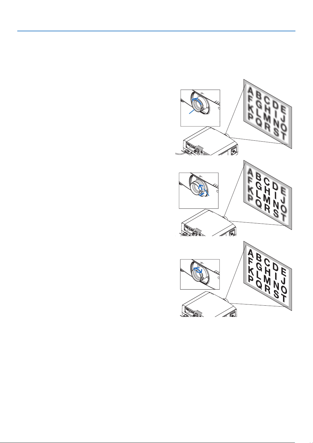
Applicable lens: NP11FL
WiththeNP11FLlens,adjustthefocusandpicturedistortion.
Preparations:
PressandholdtheSHIFT/HOMEPOSITIONbuttononthecabinetlongerthan2secondsforshiftingbackthelens
to the home position.
1.Turnthedistortionringtotheleftedge.
Distortion ring
2. Turnthefocusleverclockwiseandcounterclockwise
to adjust the focus at the center of the screen.
Focus lever
3. Usethedistortionringtocorrectthescreen’sdistortion.
(This also brings the screen peripheral area into focus.)
4. Use the focus lever to adjust the screen’s overall focus.
* If the focus at the center of the screen is off, turn the
distortion ring a little counterclockwise. The focus at the
center of the screen can now be adjusted with the focus
lever.
26
2. Projecting an Image (Basic Operation)
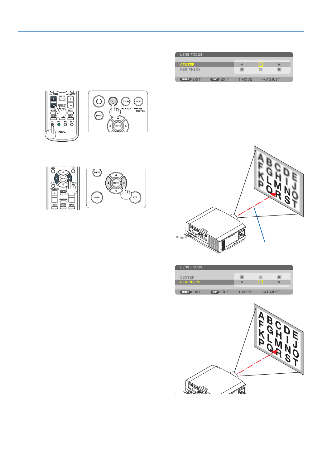
Applicable lens: NP40ZL/NP41ZL
1.PresstheFOCUSbuttononthecabinet.
The LENS FOCUS control screen will be displayed on.
* Press ◀▶ buttons to adjust focus. In another way, press
and hold the CTL button and then press VOLUME/
FOCUS +/- button on the remote control
2. WhenthecursorisontheCENTERonon-screenmenu,
press either ◀ or ▶buttontoalignfocusaroundthe
optical axis.
* The picture shows and example when the lens shift
is moved upward. The focus for the lower part of the
screen is aligned.
When the lens is at the center, the focus for the center
of the screen is aligned.
Optical axis
3. Press ▼ button to select the PERIPHERY on the on-
screen menu, and then press either ◀ or ▶ button to
alignthefocusofscreenperipheralarea.Duringthis
operation, the focus for around the optical axis will be
maintained.
27
2. Projecting an Image (Basic Operation)
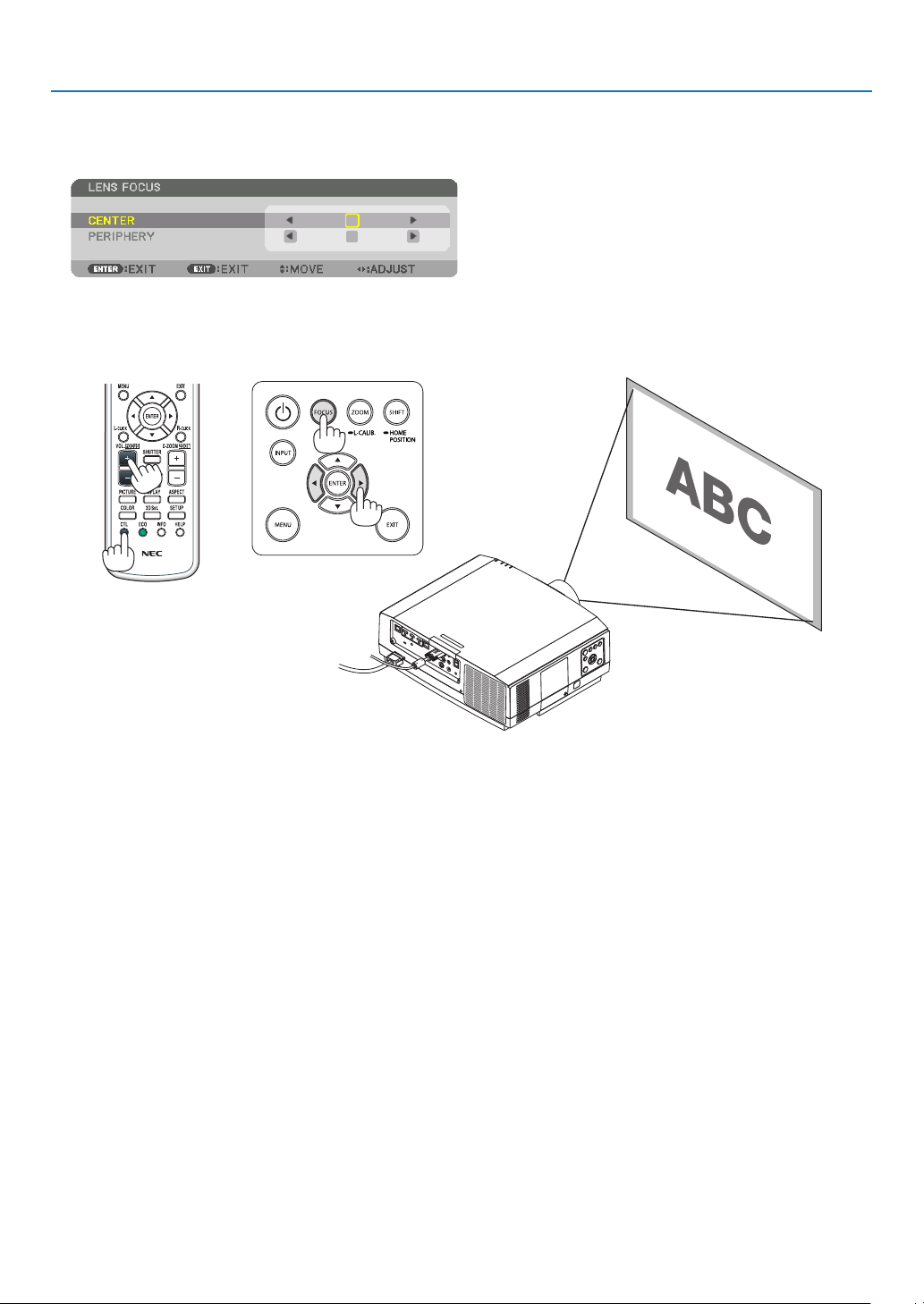
Applicable lens: NP43ZL
1. PresstheFOCUSbuttononthecabinet.
Press ◀▶ buttons to adjust focus. In another way, press and hold the CTL button and then press VOLUME/
FOCUS +/- button on the remote control.
* PERIPHERY LENS FOCUS is not available for this lens unit.
28
2. Projecting an Image (Basic Operation)
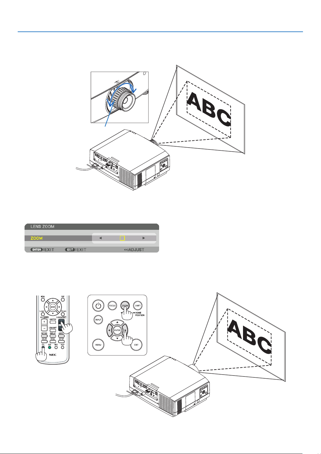
Zoom
Applicablelens:NP12ZL/NP13ZL/NP14ZL/NP30ZL
Turnthezoomringclockwiseandcounterclockwise.
Zoom ring
Applicablelensunits:NP40ZL/NP41ZL/NP43ZL
1. PressZOOM/L-CALIB.button.
The ZOOM adjustment screen will be displayed on.
• ◀ or ▶ buttons on the cabinet or the remote control are available to adjust ZOOM while the ZOOM adjustment
screen is displayed on.
• Ontheremotecontrol,whilepressingontheCTLbutton,presstheD-ZOOM/ZOOM(+)or(−)button.
The zoom is adjusted.
29
2. Projecting an Image (Basic Operation)
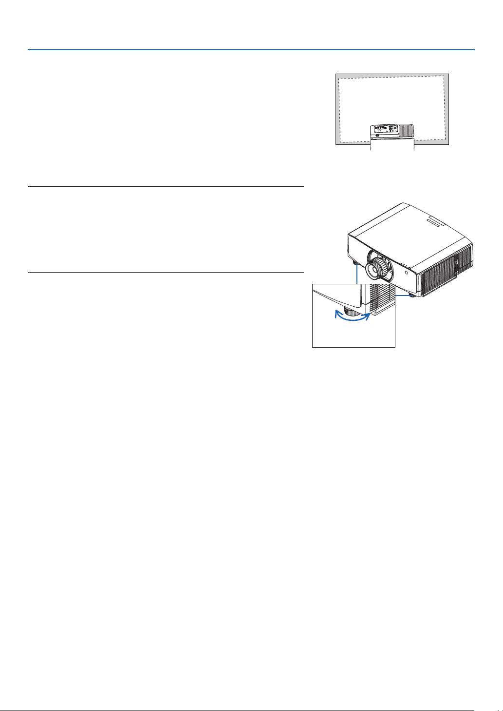
Adjusting the Tilt Foot
1.Turntheleftandrighttiltfoottoadjust.
The tilt foot lengthen and shorten when turned.
Turn one of the tilt foot to adjust the image so that it is level.
• Iftheprojectedimageisdistorted,see“3-6CorrectingHorizontal
and Vertical Keystone Distortion [CORNERSTONE]” (→ page 38)
and “[GEOMETRIC CORRECTION]” (→ page 103).
• Thetiltfootcanbelengthenedbyamaximumof20mm.
• Thetiltfootcanbeusedtotilttheprojectorbyamaximumof4°.
NOTE:
• Donotlengthenthetiltfootanymorethan20mm/0.8".Doingsowillmakethe
tiltfoot’smountsectionunstableandcouldcausethetiltfoottocomeoffthe
projector.
• Donotusethetiltfootforanypurposeotherthanadjustinginclinationofthe
projector installation angle.
Handlingthetiltfootimproperly,suchascarryingtheprojectorbygraspingthe
tilt foot or hooking it onto a wall using the tilt foot, could damage the projector.
Up
Tilt foot
Down
30
2. Projecting an Image (Basic Operation)
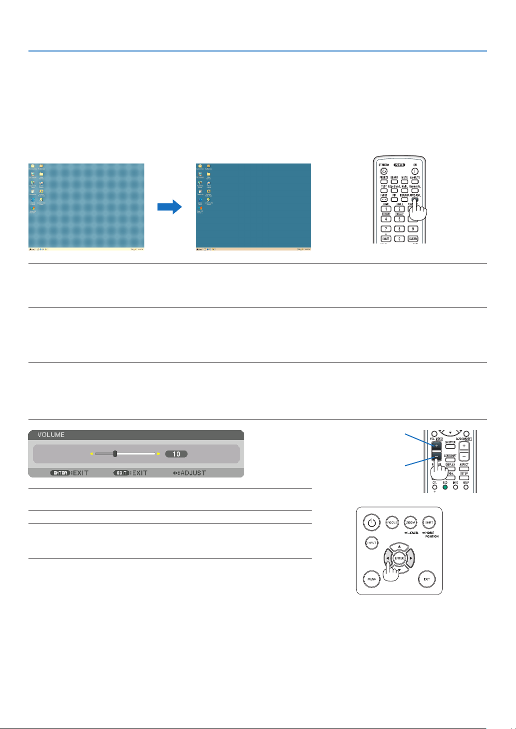
❻ Optimizing Computer Signal Automatically
Adjusting the Image Using Auto Adjust
Whenprojectingasignalfromthecomputervideoinputterminal,HDMI1inputterminal,HDMI2inputterminal,Dis-
playPortinputterminal,HDBaseTIN/Ethernetport,adjustthepicturequalitywithasingletouchofthebuttonifthe
edgesofthescreenarecutofforiftheprojectionqualityisbad.
PresstheAUTOADJ.buttontooptimizeacomputerimageautomatically.
Thisadjustmentmaybenecessarywhenyouconnectyourcomputerforthersttime.
[Poor picture] [Normal picture]
NOTE:
Somesignalsmaytaketimetodisplayormaynotbedisplayedcorrectly.
• IftheAutoAdjustoperationcannotoptimizethecomputersignal,trytoadjust[HORIZONTAL],[VERTICAL],[CLOCK],and[PHASE]
manually. (→ page 92, 93)
❼ Turning Up or Down Volume
SoundlevelfromtheAUDIOOUTterminalcanbeadjusted.
Important:
• DonotturnupthevolumetothemaximumlevelontheexternalspeakersystemconnectedtotheAUDIOOUToftheprojector.
Doingsomayproduceanunexpected,loudsoundatthetimeofturningonorofftheprojector,causingdamagetoyourhearing.
Whenadjustingthevolumeontheexternalspeakersystem,setvolumelevelofthespeakersystemtolessthanhalfitsratingand
adjust the volume on the projector to get appropriate sound level.
TIP:Whennomenusappear,the◀ and ▶ buttons on the projector cabinet work
as a volume control.
NOTE:
• Volumecontrolisnotavailablewiththe◀ or ▶ button when an image is enlarged
byusingtheD-ZOOM(+)buttonorwhenthemenuisdisplayed.
Increase volume
Decrease volume
31
2. Projecting an Image (Basic Operation)
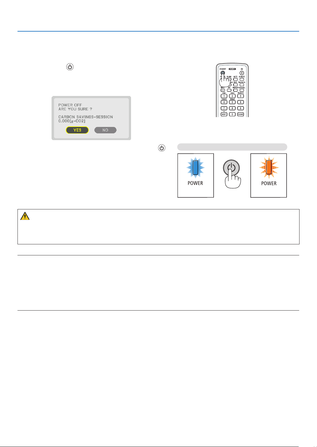
❽ Turning off the Projector
To turn off the projector:
1. First, press the (POWER) button onthe projector
cabinetortheSTANDBYbuttonontheremotecontrol.
The [POWER OFF / ARE YOU SURE ? / CARBON SAV-
INGS- SESSION 0.000[g-CO2]] message will appear.
2. Secondly, press the ENTER button or press the
(POWER)ortheSTANDBYbuttonagain.
The lamp will go off and the power supply will be cut. If
no operation is performed on the projector and no signal
is input to the projector, the projector will be in standby
state. The POWER indicator will light in orange (In the state,
the standby mode is NORMAL and the PROFILE for the
WIRED LAN is available.).
Power On
Steadily lights in
blue
Sleep
Blinks in orange
CAUTION:
PartsoftheprojectormaybecometemporarilyheatediftheprojectoristurnedoffwiththePOWERbuttonorifthe
ACpowersupplyisdisconnectedduringnormalprojectoroperation.
Usecautionwhenpickinguptheprojector.
NOTE:
• WhilethePOWERindicatorisblinkingblueinshortcycles,thepowercannotbeturnedoff.
• Youcannotturnoffthepowerfor60secondsimmediatelyafterturningitonanddisplayinganimage.
• Donotunplugthepowercordfromtheprojectororfromthepoweroutletwhileanimageisbeingprojected.Doingsocould
deterioratetheprojector’sACINterminalorthepowerplug’scontact.ToturnofftheACpowerwhileanimageisbeingprojected,
usethepowerstrip’sswitch,thebreaker,etc.
• DonotdisconnecttheACpowersupplytotheprojectorwithin10secondsofmakingadjustmentorsettingchangesandclosing
themenu.Doingsocancauselossofadjustmentsandsettings.

32
2. Projecting an Image (Basic Operation)
❾ After Use
Preparation: Make sure that the projector is turned off.
1. Unplugthepowercord.
Forpullingoutthepowerplug,pressandholdtheprotrudedsection
ontheleftandrightsidesofthepart(B).
2. Disconnectanyothercables.
3. Mount the lens cap on the lens.
4. Beforemovingtheprojector,screwinthetiltfeetiftheyhavebeenlengthened.
33
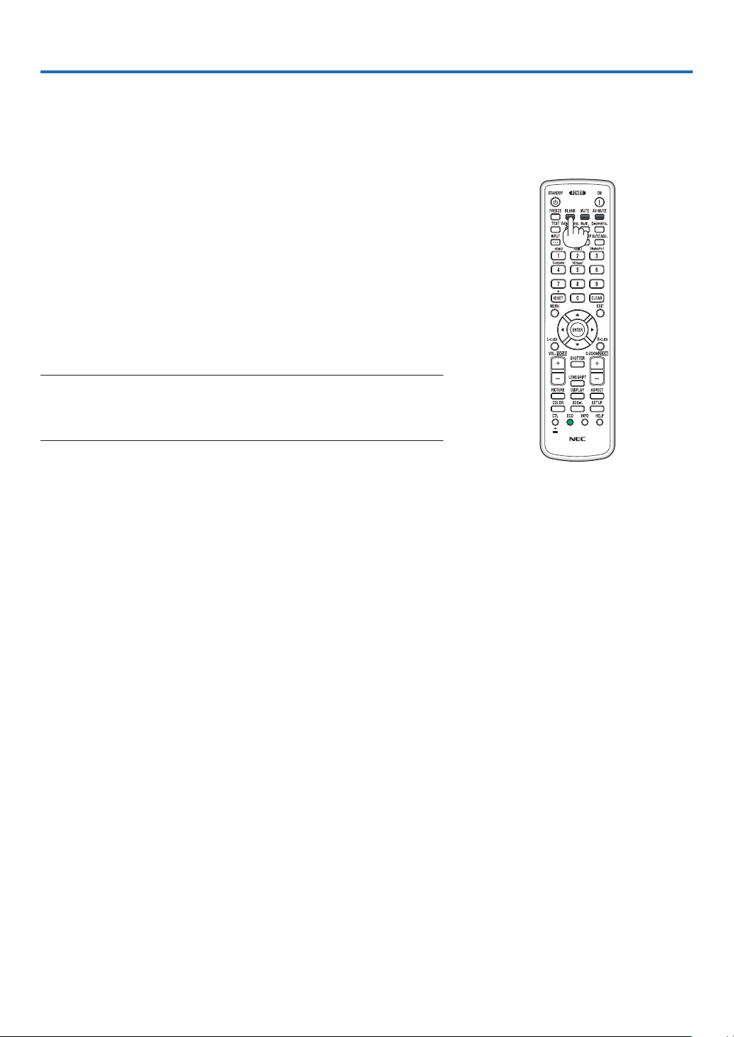
❶ Turning off the Image and Sound
Theprojectedvideoandtheoutputsoundfromthesoundoutputterminal
will disappear momentarily.
Press the BLANK button.
Theprojectedvideowillbecutoff.
Press the MUTE button.
Theaudiowillbecutoff.
PresstheAV-MUTEbutton.
Theprojectedvideoandaudiowillbecutoff.
• Pressthebuttonsonemoretimeforthecancelledvideoandaudioto
appearagain.
WhenAV-MUTEandBLANKarecontinuedforsometime,theenergy-
savingfunctionwillactivatetolowerthelamppower.
NOTE:
• Whenthe AV-MUTE and BLANK buttons are pressed immediately afterthe
energy-saving function is activated, sometimes the brightness may not return
to normal immediately.
TIP:
• Thevideowilldisappearbutnotthemenudisplay.
3. Convenient Features
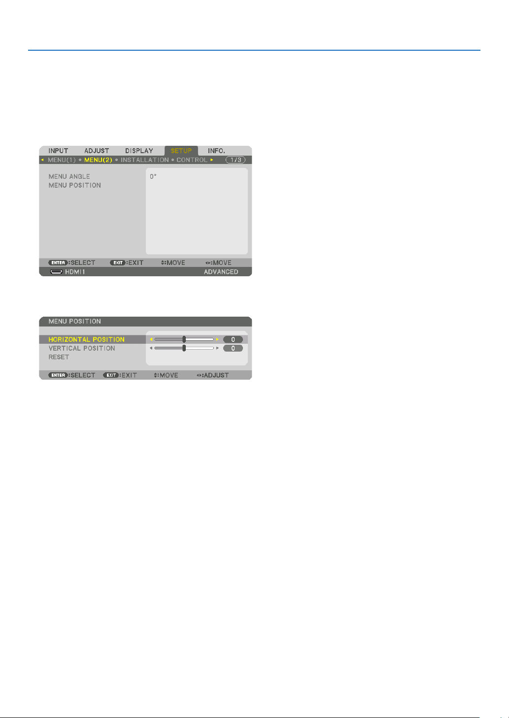
34
3. Convenient Features
❷ Shift the On-Screen Menu displaying position
1. Press the MENU button.
The On-Screen Menu will be displayed on.
2. Move the cursor by the ▶buttontothe[SETUP]andthenpresstheENTERbutton.
The cursor will move to the [MENU1].
3. Move the cursor by the ▶buttontothe[MENU2].
4. Move the cursor by the ▼buttontothe[MENUPOSITION]andthenpresstheENTER.
The On-Screen Menu will go into the MENU POSITION setup screen.
5. MovethecursoreitherTO[HORIZONTALPOSITION]or[VERTICALPOSITION]bypressing▼ or ▲ button
and then press ◀/▶
buttontoshifttheOn-ScreenMenu.
For finishing the setting on the On-Screen Menu, press the MENU button on the remote control.
TIP:
• Oncetheprojectorispoweredoff,theOn-ScreenMenudisplayingpositionwillberesettothedefaultfactorysettingposition.
• Thisfunctiondoesnotinuencetothedisplaypositionofinputterminalinformationandmessage.
• ItenablestomovethemenubymouseclickwhenacommerciallyavailableUSBmouseisconnected.
• Itenablestomovethemenupositionbythe▼▲◀ and ▶buttonsholdingtopresstheCTLbuttonontheremotecontrolor
mouse click.
• WhiletheMENUPOSITIONoftheon-screenmenuisdisplayedonandthemenuismovedbythe▼▲◀ and ▶ buttons holding
topresstheCTLbuttonontheremotecontrol,theindicationofadjustedvalueonthemenuwillnotbechanged.Inthiscase,
closetheMENUPOSITIONmenuonceanddisplayitagainforindicatingtheadjustedvalueproperly.
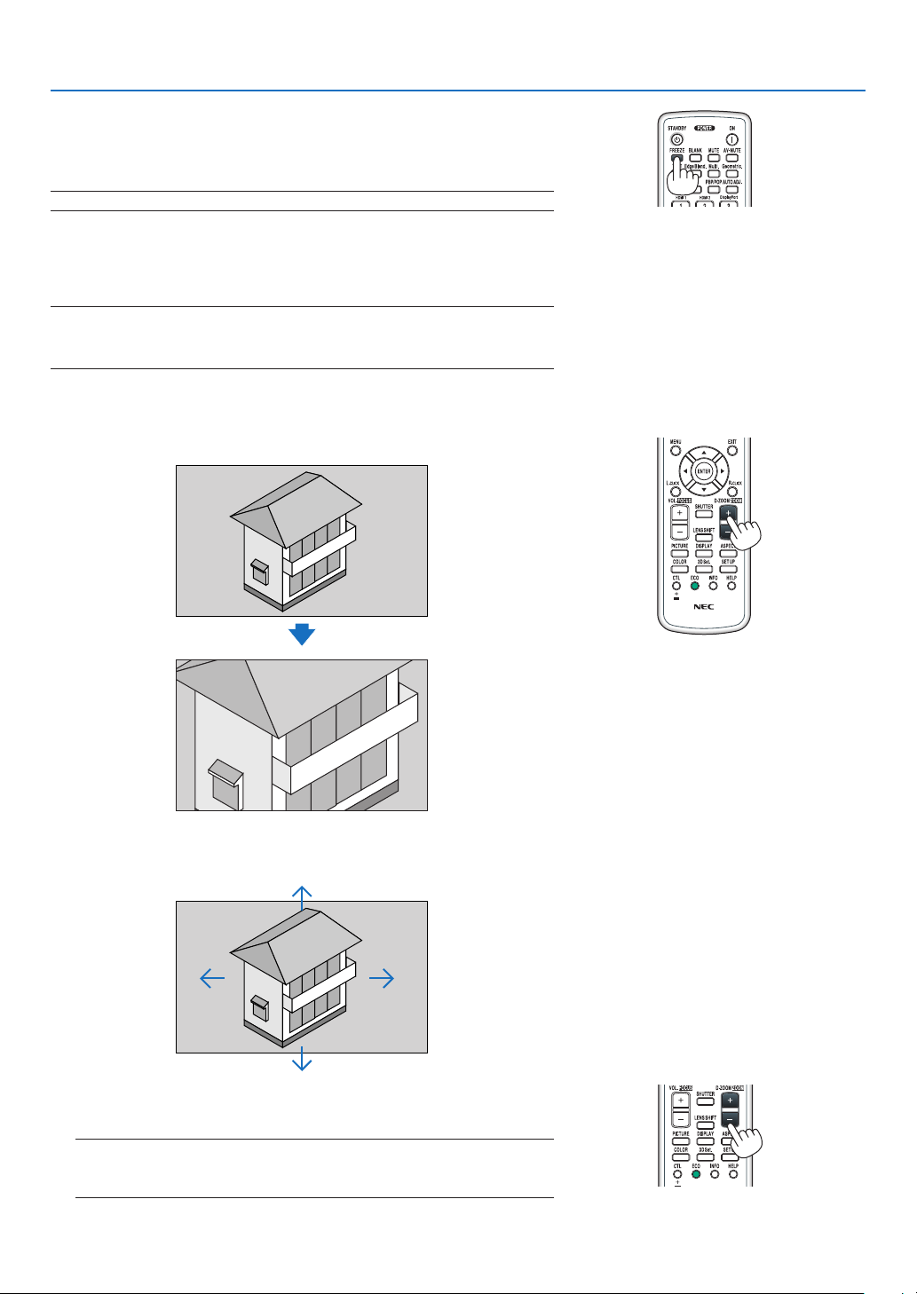
35
3. Convenient Features
❸ Freezing a Picture
PresstheFREEZEbutton to freezeapicture.Pressagain to resume
motion.
NOTE: The image is frozen but the original video is still playing back.
❹ Enlarging a Picture
Youcanenlargethepictureuptofourtimes.
NOTE:
• Dependingonaninputsignal,themaximummagnicationmaybelessthan
four times, or the function may be restricted.
Todoso:
1. PresstheD-ZOOM(+)buttontomagnifythepicture.
2. Press the ▲▼◀▶ button.
The area of the magnified image will be moved
3. PresstheD-ZOOM(−)button.
EachtimetheD-ZOOM(−)buttonispressed,theimageisreduced.
NOTE:
• Theimagewillbeenlargedorreducedatthecenterofthescreen.
• Displayingthemenuwillcancelthecurrentmagnication.

36
3. Convenient Features
❺ Changing Eco Mode/Checking Energy-Saving Effect Using
Eco Mode [ECO MODE]
Thisfeatureenablesyoutoselecttwobrightnessmodesofthelamp:
OFFandONmodes.Thelamplifecanbeextendedbyturningonthe[ECOMODE].
[ECOMODE] Description
[OFF]
Thisisthedefaultsetting(100%Brightness).
[ON] Lowlamppowerconsumption(approx.70%Brightness).
Toturnonthe[ECOMODE],dothefollowing:
1. PresstheECObuttonontheremotecontroltodisplay[LIGHTMODE]screen.
2. Use the ▲ or ▼buttontoselect[ECOMODE].
3. Use the ▲ or ▼buttontoselect[ON].
4. PresstheENTERbutton.
To change from [ON] to [OFF], Go back to Step 2 and select [OFF]. Repeat Step 3.
NOTE:
• The[ECOMODE]canbechangedbyusingthemenu.
Select[SETUP]→[INSTALLATION]→[LIGHTMODE]→[ECOMODE].
• Thelampliferemainingandlamphoursusedcanbecheckedin[USAGETIME].Select[INFO.]→[USAGETIME].
• [ECOMODE]isalwayssetto[OFF]for1minuteimmediatelyafterthelampisturnedon.Thelampconditionwillnotbeaffected
evenwhen[ECOMODE]ischanged.
• Afteralapseof1minutefromwhentheprojectordisplaysablue,blackorlogoscreen,[ECOMODE]willautomaticallyswitchto
[ON].
• Iftheprojectorisoverheatedin[OFF]mode,theremaybeacasewherethe[ECOMODE]automaticallychangesto[ON]mode
toprotecttheprojector.Thisiscalled“ForcedECOMode”.WhentheprojectorisintheForcedEcoMode,thepicturebrightness
decreasesslightlyandtheTEMP.indicatorlightsupinorange.AtthesametimetheThermometersymbol[ ]isdisplayedat
the bottom right of the screen.
Whentheprojectorcomesbacktonormaltemperature,theForcedEcoModeiscancelledandthe[ECOMODE]returnsto[OFF]
mode.
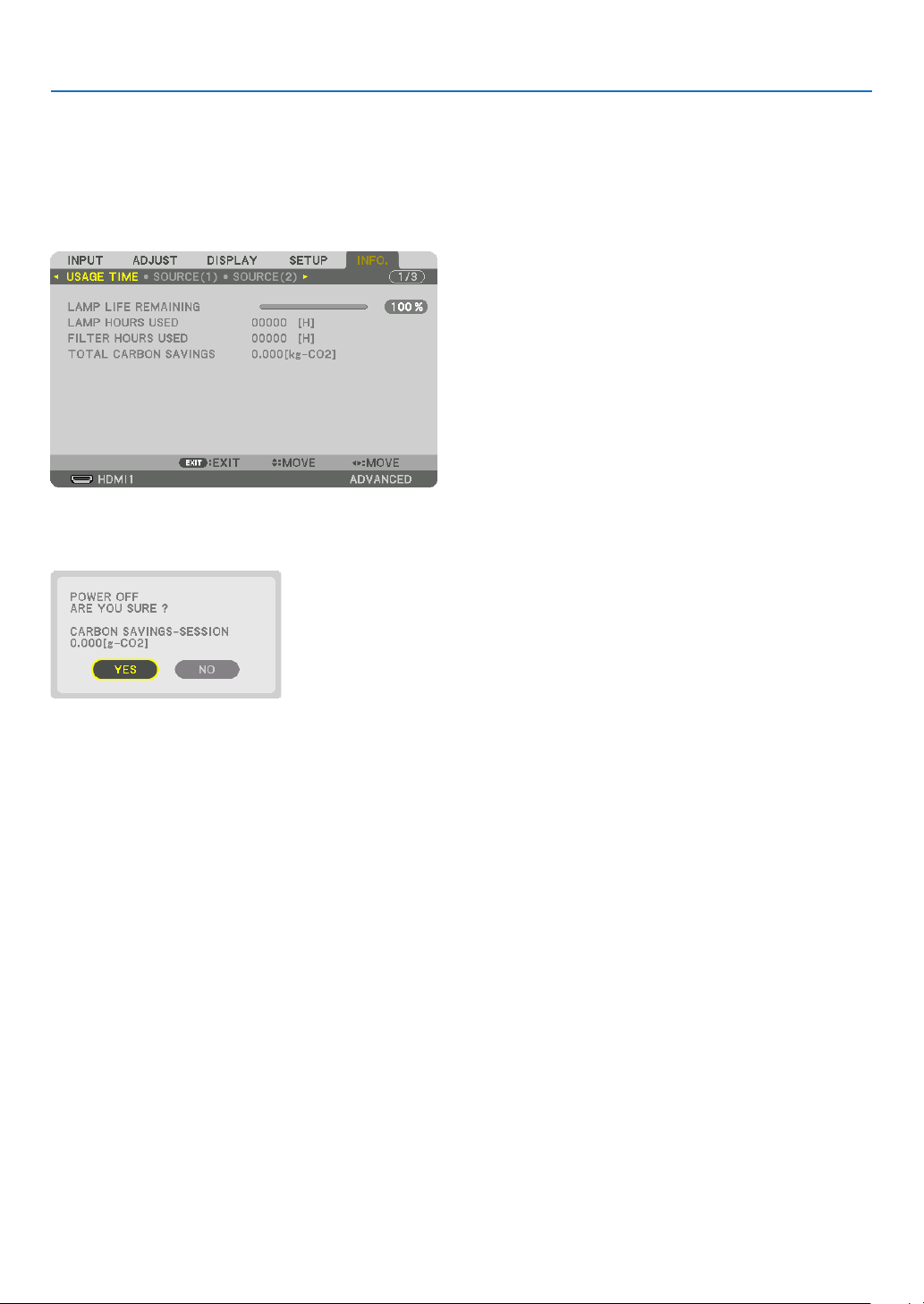
37
3. Convenient Features
Checking Energy-Saving Effect [CARBON METER]
Thisfeaturewillshowenergy-savingeffectintermsofCO
2
emissionreduction(kg)whentheprojector’s[ECOMODE]
issetto[OFF],or[ON].Thisfeatureiscalledas[CARBONMETER].
Therearetwomessages:[TOTALCARBONSAVINGS]and[CARBONSAVINGS-SESSION].The[TOTALCARBON
SAVINGS]messageshowsthetotalamountofCO
2
emissionreductionfromthetimeofshipmentuptonow.Youcan
checktheinformationon[USAGETIME]from[INFO.]ofthemenu.(→page136)
The[CARBONSAVINGS-SESSION]messageshowstheamountofCO
2
emission reduction between the time of
changingtoECOMODEimmediatelyafterthetimeofpower-onandthetimeofpower-off.The[CARBONSAVINGS-
SESSION]messagewillbedisplayedinthe[POWEROFF/AREYOUSURE?]messageatthetimeofpower-off.
TIP:
• TheformulaasshownbelowisusedtocalculatetheamountofCO
2
emission reduction.
AmountofCO
2
emissionreduction=(PowerconsumptioninOFFforECOMODE−PowerconsumptioninONforECOMODE)×
CO
2
conversionfactor.*WhentheimageisturnedoffwiththeAV-MUTEbuttontheamountofCO
2
emmission reduction will also
increase.
* CalculationforamountofCO
2
emissionreductionisbasedonanOECDpublication“CO
2
EmissionsfromFuelCombustion,
2008Edition”.
• The[TOTALCARBONSAVINGS]iscalculatedbasedonsavingsrecordedin15minutesintervals.
• Thisformulawillnotapplytothepowerconsumptionwhichisnotaffectedbywhether[ECOMODE]isturnedonoroff.
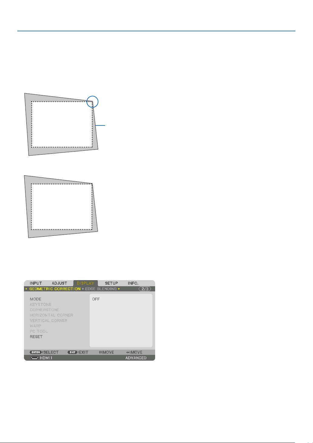
38
3. Convenient Features
❻ Correcting Horizontal and Vertical Keystone Distortion
[CORNERSTONE]
Usethe[CORNERSTONE]featuretocorrectkeystone(trapezoidal)distortiontomakethetoporbottomandtheleft
orrightsideofthescreenlongerorshortersothattheprojectedimageisrectangular.
1. Projectanimagesothatthescreenissmallerthantheareaoftheraster.
Projected image
The drawing shows the upper right corner.
2. Pickupanyoneofthecornersandalignthecorneroftheimagewithacornerofthescreen.
3. PresstheGeometric.buttoneitheronthecabinetortheremotecontrol.
Display the [GEOMETRIC CORRECTION] screen of the on-screen menu.
4. Movethecursoronto[MODE]by▼buttonandpresstheENTER.
The mode selection screen will displayed on.
5. Select[CORNERSTONE]andpresstheENTER.
Go back to display the [GEOMETRIC CORRECTION] screen of the on-screen menu.
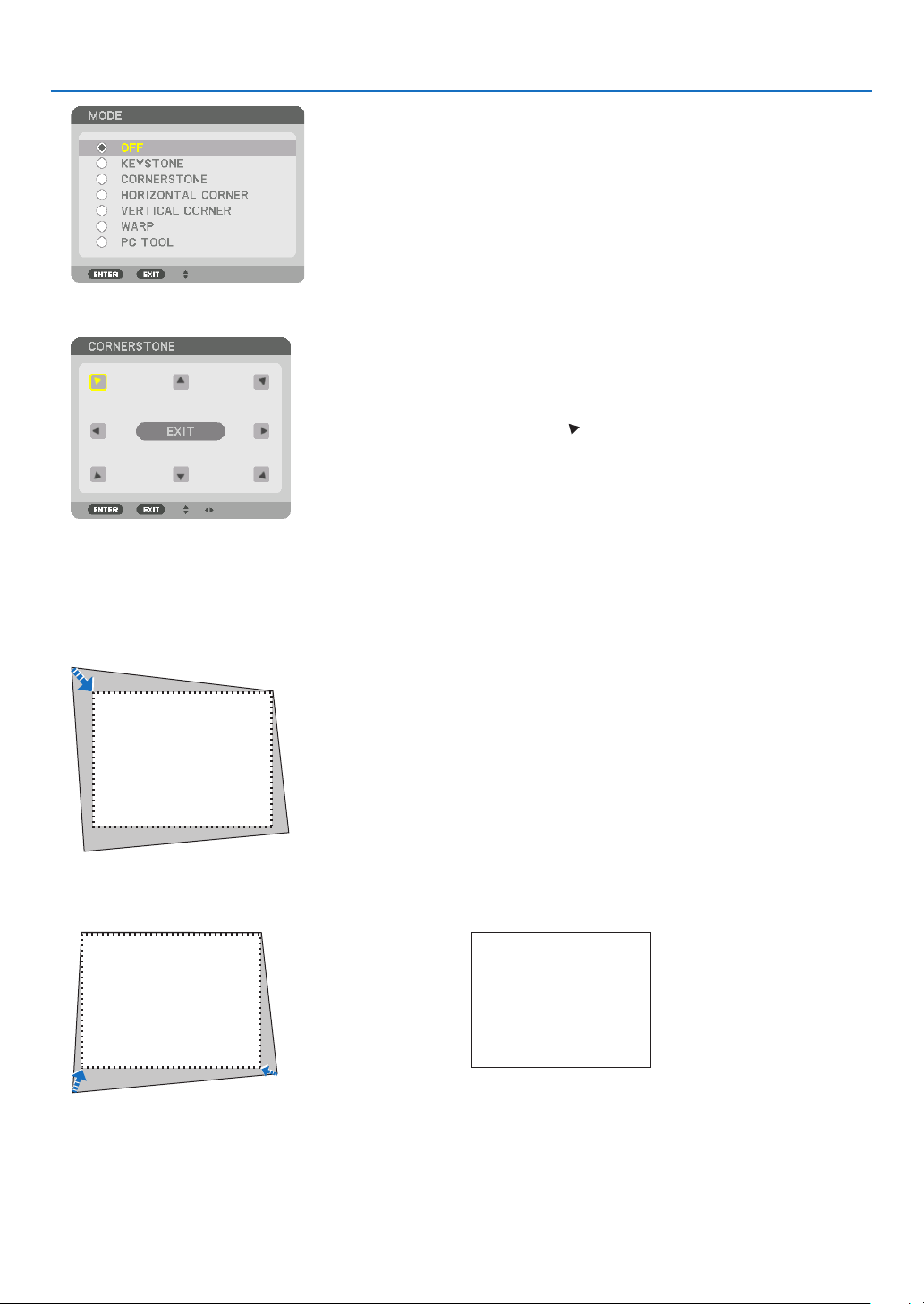
39
3. Convenient Features
6. Pressthe▼buttontoalignwiththe[CORNERSTONE]andthenpresstheENTERbutton.
The drawing shows the upper left icon ( ) is selected.
The screen will switch to the [CORNERSTONE] screen.
7. Use the ▲▼◀▶ button to select one icon (▲) which points in the direction you wish to move the projected
imageframe.
8. PresstheENTERbutton.
9. Use the ▲▼◀▶buttontomovetheprojectedimageframeasshownontheexample.
10
.PresstheENTERbutton.
11
. Use the ▲▼◀▶ button to select another icon which points in the direction.
On the [CORNERSTONE] screen, select [EXIT] or press the EXIT button on the remote control.

40
3. Convenient Features
The confirmation screen is displayed.
12
. Press the ◀ or ▶buttontohighlightthe[OK]andpresstheENTERbutton.
This completes the [CORNERSTONE] correction.
• Select[CANCEL]andpresstheENTERbuttontoreturntothe[CORNERSTONE]screen.
Selecting[CANCEL]willreturntotheadjustmentscreenwithoutsavingchanges(Step3).
Selecting[RESET]willreturntothefactorydefault.
Selecting[UNDO]willexitwithoutsavingchanges.
NOTE:
• Evenwhentheprojectoristurnedon,thelastusedcorrectionvaluesareapplied.
• Carryouteitheroneofthefollowingactionstocleartheadjustmentvalueof[CORNERSTONE].
• InStep11,select[RESET]andthenpresstheENTERbutton.
• Inthestate[CORNERSTONE]hasbeenselectedfor[MODE]inthe[GEOMETRICCORRECTION]:
• PresstheGeometric.buttonfor2ormoreseconds.
• Run[DISPLAY]→[GEOMETRICCORRECTION]→[RESET]intheon-screenmenu.
• UsingCORNERSTONEcorrectioncancausetheimagetobeslightlyblurredbecausethecorrectionismadeelectronically.
• AcommerciallyavailableUSBmouseisavailableforCORNERSTONEcorrection.
❼ Operation for the On-Screen Menu by a commercially
available USB mouse
OnceacommerciallyavailableUSBmouseisconnectedtothisprojector,itenablestoperformtheoperationforthe
on-screenmenuandthegeometriccorrectioneasily.
NOTE:
• NotguaranteetheperformanceofallUSBmouseavailableonthemarket.
Menu operation
① Displaytheon-screenmenubyrightclick.
② Selectadesiredmenuandperformadjustmentbyleftclick.
Theadjustmentbarcanbecontrolbydraganddrop.
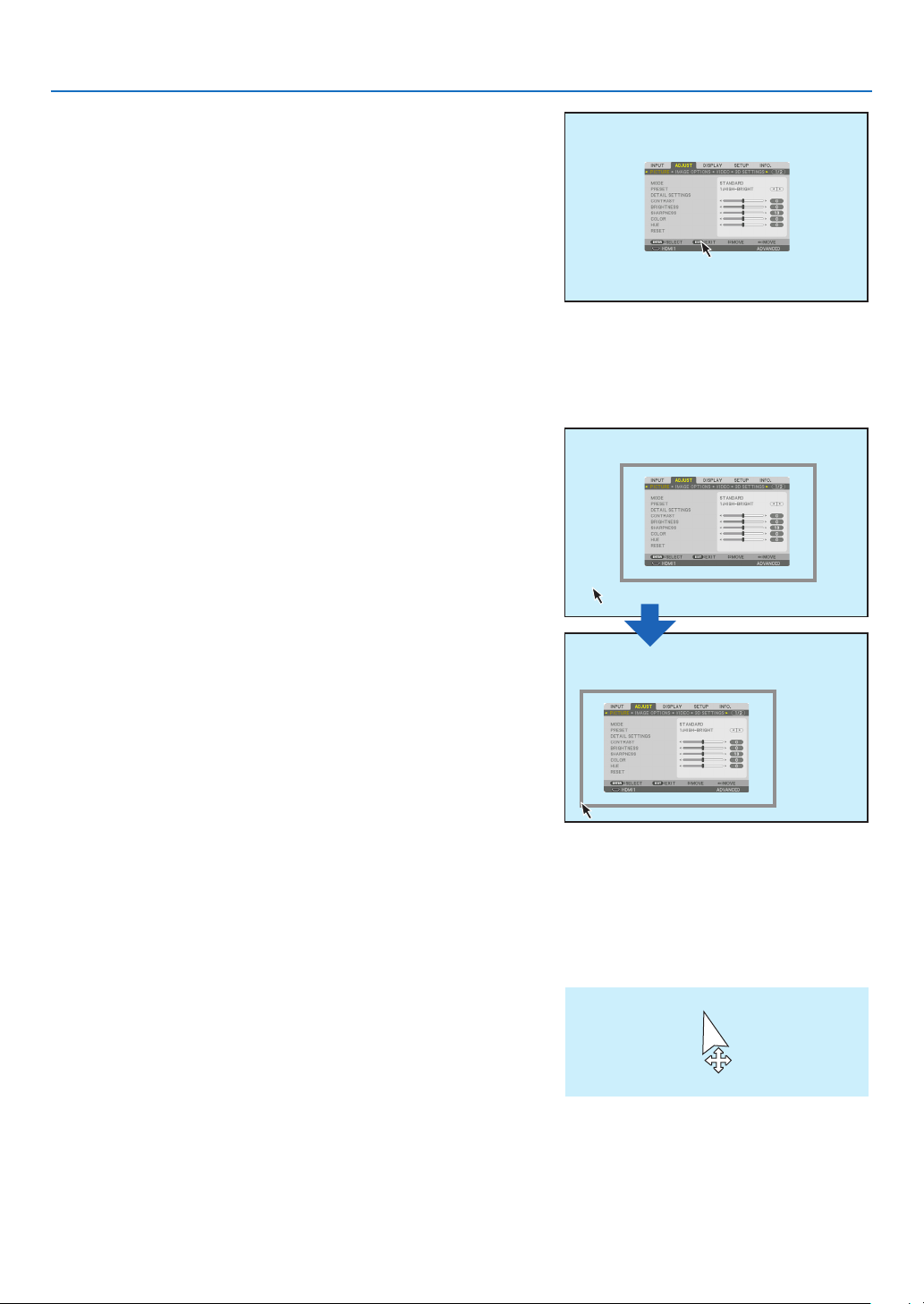
41
3. Convenient Features
③ Select[EXIT]displayedatthebottomofthemenubyleftclickfor
goingbacktothepreviouslevel.Ifthecursorisonthemainmenu
option,itworksforclosingthemenu.(Itworksasthesameperfor-
mancewiththe[EXIT]buttonontheremotecontrol.
Menu position control
① Clickthe wheel buttontodisplaytheon-screenmenuindication
frame.
②
Leftclickatthepositionontheprojectionscreenwhereyouwant
toshifttheon-screenmenu.Thenearestcorneroftheon-screen
menuindicationframewillshifttotheclickedposition.
③ Clickthewheelbuttontoclosethemenuindicationframe.
Geometric correction
TheUSBmousecanbeusedforCORNERSTONECORRECTION,HORIZONTALCORNER,VERTICALCORNER
andWARP.Inthisclause,theCORNERSTONECORRECTIONbyanUSBmouseisexplainedasanexample.
① WhiletheadjustmentscreenoftheCORNERSTONE
CORRECTION is displayed, right click on the pro-
jection screen.The shape of mouse pointerwill be
changedandthecorrectionwillbecomeavailable.
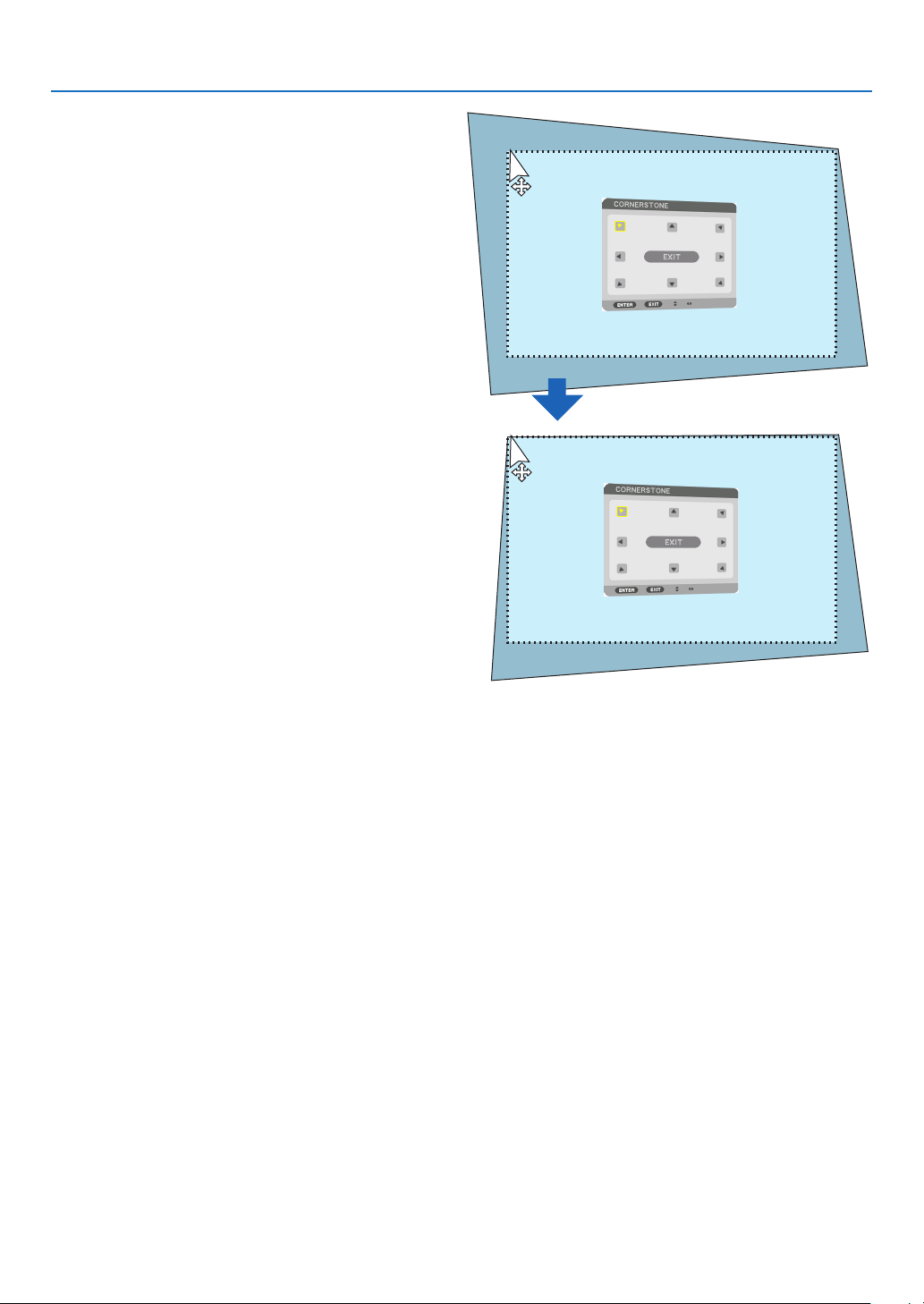
42
3. Convenient Features
② Leftclickatthescreencorner.Theprojectionscreen
cornerwillmovetothemouseclickedposition.
③ Repeatthestep②forcorrectingalldistortion.After
completionofdistortioncorrection,rightclickonthe
projectionscreen.Theshapeofmousepointerwillbe
changedtonormal.
④ Leftclick[EXIT]onthecorrectionscreentonish.
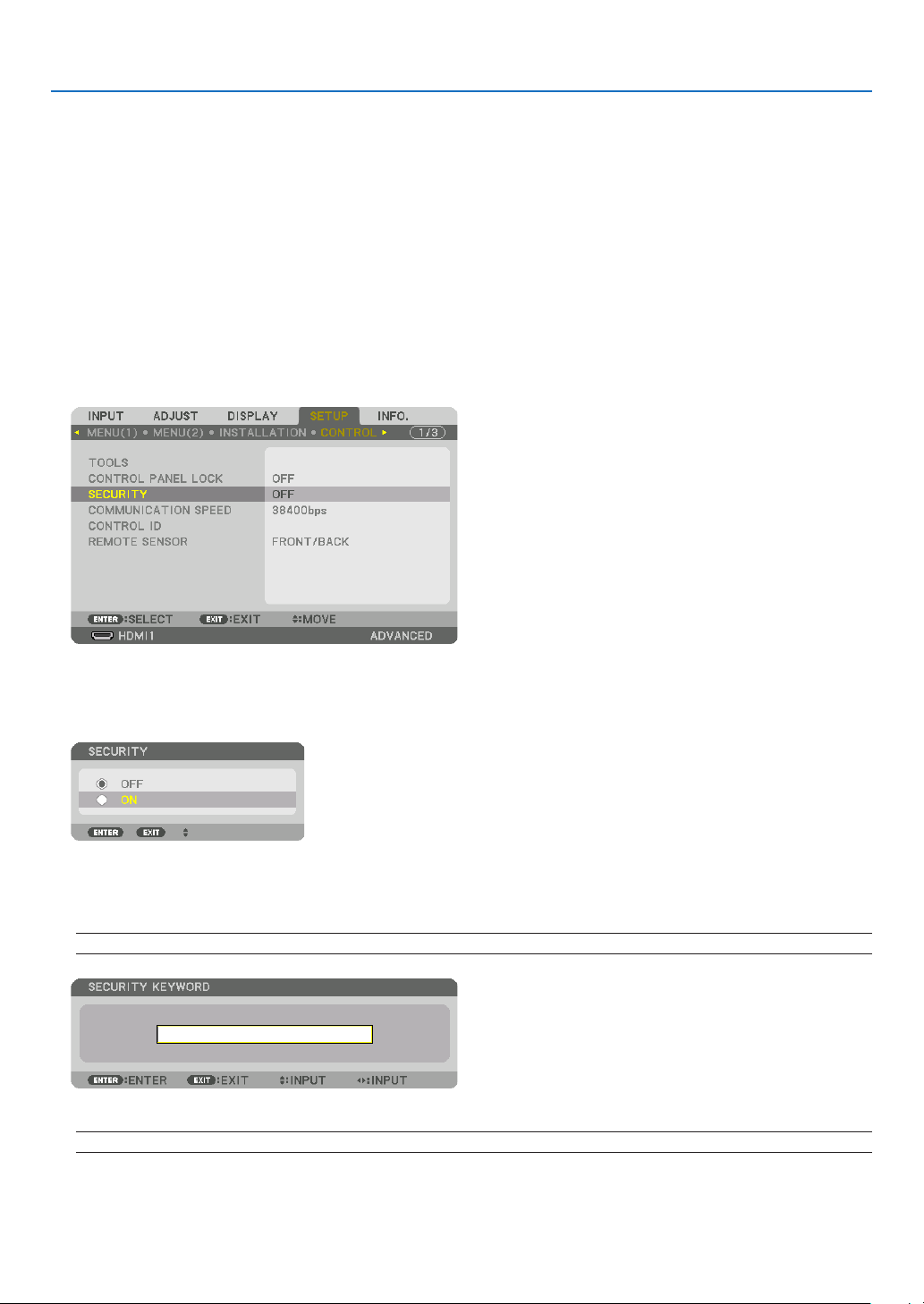
43
3. Convenient Features
❽
Preventing the Unauthorized Use of the Projector [SECURITY]
AkeywordcanbesetforyourprojectorusingtheMenutoavoidoperationbyanunauthorizeduser.Whenakeyword
isset,turningontheprojectorwilldisplaytheKeywordinputscreen.Unlessthecorrectkeywordisentered,thepro-
jectorcannotprojectanimage.
•The[SECURITY]settingcannotbecancelledbyusingthe[RESET]ofthemenu.
To enable the Security function:
1. Press the MENU button.
The menu will be displayed.
2. Press the ▶buttontwicetoselect[SETUP]andpressthe▼buttonortheENTERbuttontoselect[MENU(1)].
3. Press the ▶buttontoselect[CONTROL].
4. Press the ▼buttonthreetimestoselect[SECURITY]andpresstheENTERbutton.
The OFF/ON menu will be displayed.
5. Press the ▼buttontoselect[ON]andpresstheENTERbutton.
The [SECURITY KEYWORD] screen will be displayed.
6. Typeinacombinationofthefour▲▼◀▶buttonsandpresstheENTERbutton.
NOTE: A keyword must be 4 to 10 digits in length.
The [CONFIRM KEYWORD] screen will be displayed.
NOTE:Makeanoteofyourpasswordandstoreitinasafeplace.
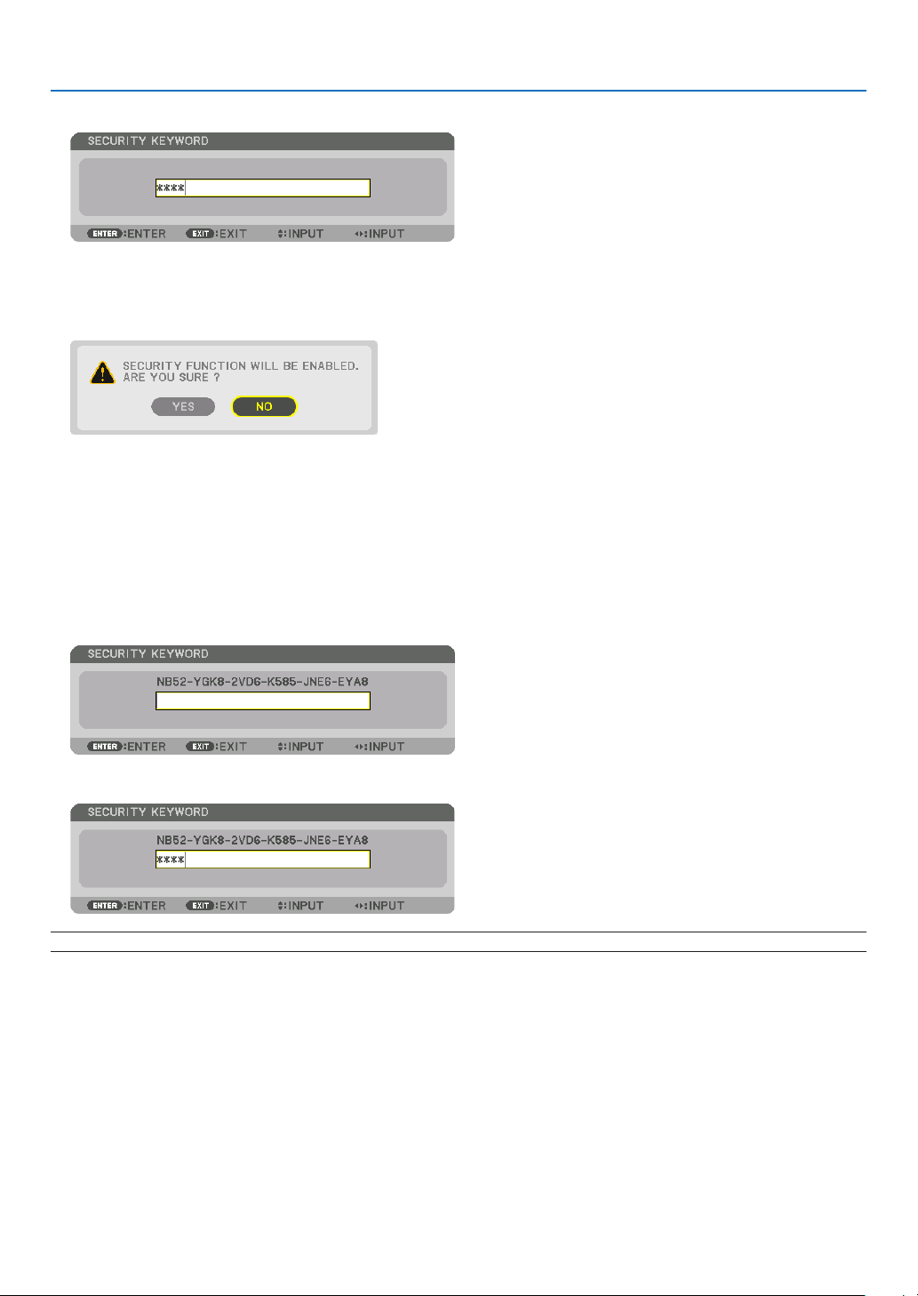
44
3. Convenient Features
7. Typeinthesamecombinationof▲▼◀▶buttonsandpresstheENTERbutton.
The confirmation screen will be displayed.
8. Select[YES]andpresstheENTERbutton.
The SECURITY function has been enabled.
To turn on the projector when [SECURITY] is enabled:
1. PressthePOWERbutton.
The projector will be turned on and display a message to the effect that the projector is locked.
2. Press the MENU button.
3. TypeinthecorrectkeywordandpresstheENTERbutton.Theprojectorwilldisplayanimage.
NOTE: The security disable mode is maintained until the main power is turned off or unplugging the power cord.
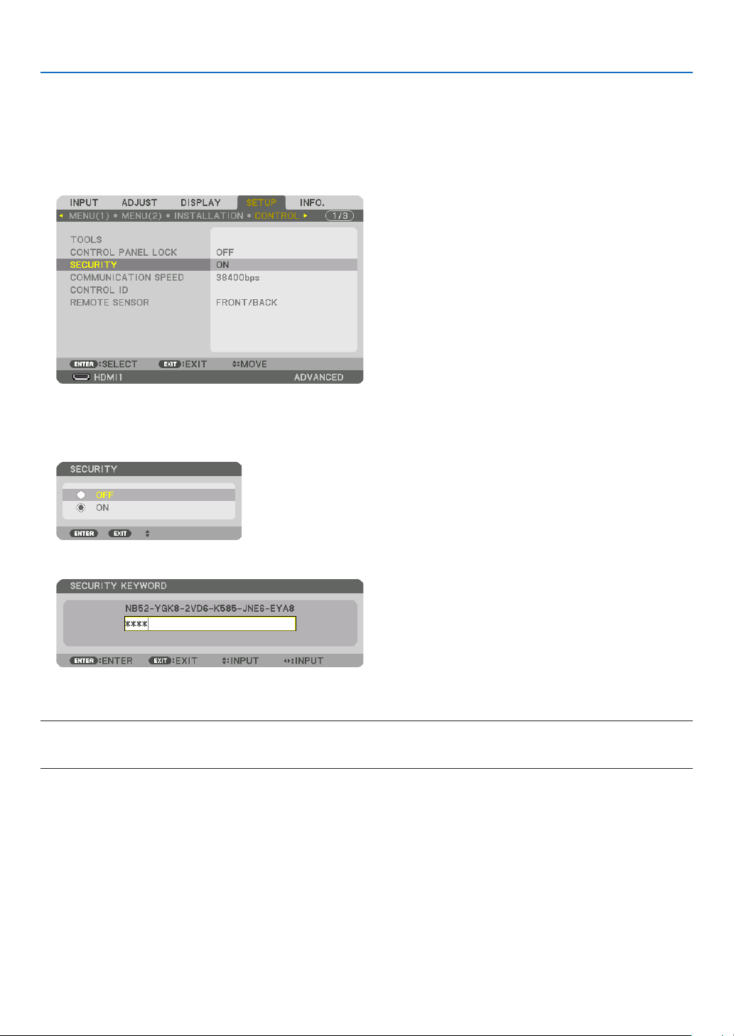
45
3. Convenient Features
To disable the SECURITY function:
1. Press the MENU button.
The menu will be displayed.
2.Select[SETUP]→[CONTROL]→[SECURITY]andpresstheENTERbutton.
The OFF/ON menu will be displayed.
3. Select[OFF]andpresstheENTERbutton.
The SECURITY KEYWORD screen will be displayed.
4. TypeinyourkeywordandpresstheENTERbutton.
When the correct keyword is entered, the SECURITY function will be disabled.
NOTE:Ifyouforgetyourkeyword,contactyourdealer.Yourdealerwillprovideyouwithyourkeywordinexchangeforyourrequest
code.YourrequestcodeisdisplayedintheKeywordConrmationscreen.Inthisexample[NB52-YGK8-2VD6-K585-JNE6-EYA8]
is a request code.

46
3. Convenient Features
❾ Projecting 3D videos
Thisprojectorcanbeusedtowatchvideosin3Dusingcommercially-availableactiveshutter-type3Deyewear.In
ordertosynchronizethe3Dvideoandeyewear,acommercially-available3Demitterneedstobeconnectedtothe
projector(ontheprojectorside).
The3Deyewearreceivesinformationfromthe3Demitterandperformsopeningandclosingontheleftandright.
CAUTION
Health precautions
Beforeuse,pleasemakesuretoreadanyhealthprecautionsthatmaybestatedintheoperatingmanualsenclosed
withthe3Deyewearand3Dvideosoftware(Blu-rayplayer,games,computeranimationles,etc.).
Pleasetakenoteofthefollowinginordertoavoidadversehealtheffects.
• Pleasedonotusethe3Deyewearforpurposesotherthantowatch3Dvideos.
• Pleasekeepadistanceofatleast2mawayfromthescreenwhenwatchingvideos.Watchingavideotooclose
tothescreenwillincreaseeyefatigue.
• Pleasedonotwatchvideoscontinuouslyforalongperiodoftime.Pleasetakea15minutes’breakafterevery
hourofwatching.
• Pleaseconsultadoctorbeforewatchingifyouoranyofyourfamilymembershaveahistoryofsufferingfrom
seizurescausedbylightsensitivity.
• Pleasestopwatchingimmediatelyandtakearestwhenyoufeelphysicallyunwellwhilewatching(vomiting,gid-
diness,nausea,headaches,soreeyes,blurredvision,crampsanddumbnessinthelimbs,etc.).Pleaseconsult
a doctor if the symptoms persist.
• Pleasewatcha3Dvideodirectlyinfrontofthescreen.Ifyouwatcha3Dvideoobliquelyfromthesides,this
mayresultinphysicalandeyefatigue.
3D eyewear and 3D emitter preparations
Pleaseuseanactiveshutter-type3DeyewearthatconformswiththeVESAstandard.
Acommercially-availableRFtypemadebyXpandisrecommended.
3D eyewear ������������ Xpand X105-RF
3D emitter
�������������� Xpand AD025-RF-X1
Procedure to watch 3D videos using this projector
1. Connectthevideodevicetotheprojector.
2. Switch on the power supply to the projector.
3. Runthe3Dvideosoftwareandprojectthevideousingtheprojector.
This has been automatically set up when shipped from the factory. When a 3D video cannot be projected, it may
be because the 3D detection signals are not included or because they are not detectable by the projector.
Please manually select the format.
4. Selectthe3Dvideoformat.
(1) Press the “3D Set.” button on the remote control.

47
3. Convenient Features
The [3D SETTINGS] screen will be displayed.
(2) Press the ▼ button to align the cursor with the [FORMAT] and press the ENTER button.
The format screen will be displayed.
(3) Select the input signal format using the ▼ button and then press the ENTER button.
The 3D settings screen will disappear and the 3D video will be projected.
Press the MENU button and the on-screen menu will disappear.
The 3D caution message screen will be displayed when switching to a 3D video (default factory setting when
shipped). Please read the “Health Precautions” on the previous page to watch videos in the correct manner. The
screen will disappear after 60 seconds or when the ENTER button is pressed. (→ page 112)
5. Turnonthepowersupplyofthe3Deyewearandweartheeyeweartowatchthevideo.
A normal video will be shown when a 2D video is input.
To watch a 3D video in 2D, select [OFF(2D)] in the [FORMAT] screen mentioned above in (3).
NOTE:
• Uponswitchingto3Dimage,thefollowingfunctionswillbecancelledanddisabled.[BLANKING],[PIP/PICTUREBYPICTURE],
[GEOMETRICCORRECTION],[EDGEBLENDING]([GEOMETRICCORRECTION]and[EDGEBLENDING]adjustmentvalueswill
be maintained.)
• Theoutputmaynotautomaticallyswitchtoa3Dvideodependingonthe3Dinputsignal.
• ChecktheoperatingconditionsdescribedintheusermanualoftheBlu-rayplayer.
• PleaseconnecttheDINterminalofthe3Demittertothe3DSYNCofthemainprojector.
• The3Deyewearallowsvideostobeviewedin3Dbyreceivingsynchronizedopticalsignalsoutputfromthe3Demitter.
Asaresult,the3Dimagequalitymaybeaffectedbyconditionssuchasthebrightnessofthesurroundings,screensize,viewing
distance, etc.
• Whenplayinga3Dvideosoftwareonacomputer,the3DimagequalitymaybeaffectedifthecomputerCPUandgraphicschip
performance are low. Please check the required operating environment of the computer that is stated in the operating manual
attachedtothe3Dvideosoftware.
• Dependingonthesignal,[FORMAT]and[L/RINVERT]maynotbeabletobeselected.Pleasechangethesignalinthatcase.

48
3. Convenient Features
When videos cannot be viewed in 3D
Pleasecheckthefollowingpointswhenvideoscannotbeviewedin3D.
Pleasealsoreadtheoperatingmanualattachedtothe3Deyewear.
Possible reasons Solutions
The selected signal does not support 3D output� Please change the video signal input to one that supports 3D�
The format for the selected signal is turned to [OFF(2D)]� Please change the format in the on-screen menu to [AUTO] or a
format that supports 3D�
A eyewear that is not supported by the projector is being used� Please purchase a commercially-available 3D eyewear or 3D emitter
(recommended)� (→ page 46)
Please check the following points when a video cannot be viewed in
3D using a 3D eyewear that is supported by the projector�
The power supply of the 3D eyewear is turned off� Please turn on the power supply of the 3D eyewear�
The internal battery of the 3D eyewear is flat� Please charge or replace the battery�
The viewer is located too far away from the screen� Please get closer to the screen until the video can be seen in 3D�
Please turn the L/R INVERT in the on-screen menu to [OFF]�
Due to multiple 3D projectors working at the same time in the vi-
cinity, the projectors may interfere with one another� Alternatively,
there may be a bright light source near the screen�
Please maintain sufficient distance between the projectors�
Please keep the light source away from the screen�
Please turn the L/R INVERT in the on-screen menu to [OFF]�
There is an obstacle between the optical receiver of the 3D eyewear
and the 3D emitter�
Please remove the obstacle�
The 3D format of the 3D video contents is not supported� Please check with the company selling the 3D video contents�

49
3. Convenient Features
❿ Controlling the Projector by Using an HTTP Browser
Overview
Usingthewebbrowseronthecomputer,theHTTPserverscreenoftheprojectorcanbedisplayedtooperatethe
projector.
Possible operations on the HTTP server screen
• Congurethesettingsrequiredforconnectingtheprojectortothenetwork(wiredLAN).(NETWORKSETTINGS)
• Conguretheemailnotication.(ALERTMAIL)
Whentheprojectorisconnectedtoanetwork(wiredLAN),noticationsonthelampreplacementperiodandvari-
ous errors are sent to the email address that has been set up.
• Operatetheprojector.
Operationssuchpoweron/offoftheprojector,inputterminalswitchover,volumecontrol,picturecontrol,andlens
control etc. can be carried out.
• Congurethe[PJLinkPASSWORD],[AMXBEACON],and[CRESTRON]etc.
To view the HTTP server screen
1. ConnecttheprojectortothecomputerwithaLANcablesoldcommercially.(→page152)
2. Select[SETUP]→[NETWORKSETTINGS]→[WIREDLAN]intheon-screenmenutoconfigurethenetwork
settings.(→page126)
3. StartupthewebbrowseronyourcomputerandentertheaddressorURLintheinputfield.
Specify the address or URL as “http://<IP Address of Projector>/index.html”.
The basic HTTP server screen will be displayed.
TIP:ThefactorysettingIPaddressis[DHCPON].
NOTE:
• Tousetheprojectorinanetwork,consultwithyournetworkadministratoraboutnetworksettings.
• Thedisplay’sorbutton’sresponsecanbesloweddownoroperationmaynotbeaccepteddependingthesettingsofyournetwork.
Shouldthishappen,consultyournetworkadministrator.Theprojectormaynotrespondifitsbuttonsarerepeatedlypressedin
rapidintervals.Shouldthishappen,waitamomentandrepeat.Ifyoustillcan’tgetanyresponse,turnoffandbackontheprojec-
tor.
• IfthePROJECTORNETWORKSETTINGSscreendoesnotappearinthewebbrowser,presstheCtrl+F5keystorefreshyourweb
browser (or clear the cache).
• Thisprojectoruses“JavaScript”and“Cookies”andthebrowsershouldbesettoacceptthesefunctions.Thesettingmethodwill
vary depending on the version of browser. Please refer to the help files and the other information provided in your software.
Preparation before Use
ConnecttheprojectortoacommerciallyavailableLANcablebeforeengaginginbrowseroperations.(→page152)
Operationwithabrowserthatusesaproxyservermaynotbepossibledependingonthetypeofproxyserverandthe
settingmethod.Althoughthetypeofproxyserverwillbeafactor,itispossiblethatitemsthathaveactuallybeenset
willnotbedisplayeddependingontheeffectivenessofthecache,andthecontentssetfromthebrowsermaynotbe
reectedinoperation.Itisrecommendedthataproxyservernotbeusedunlessitisunavoidable.
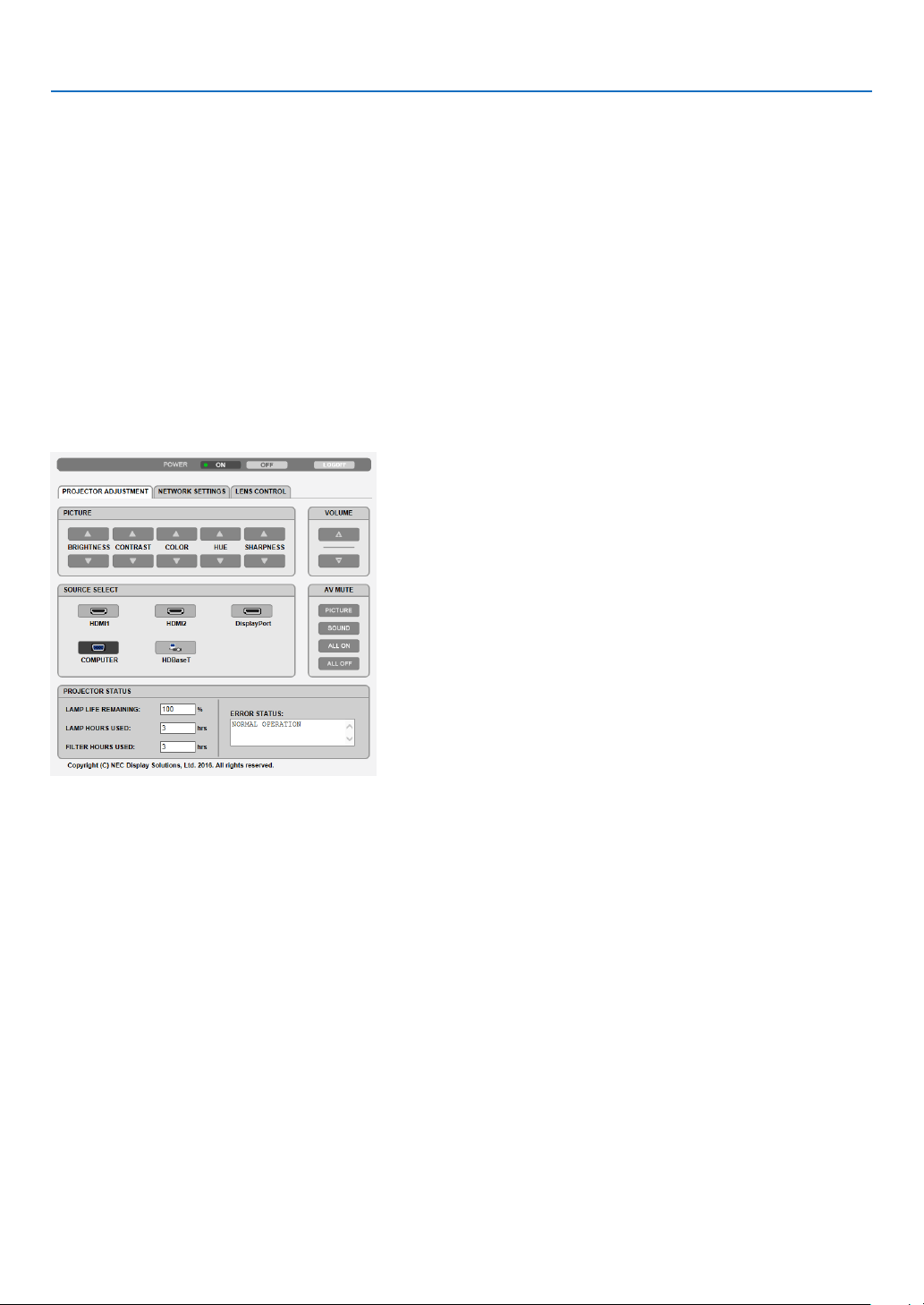
50
3. Convenient Features
Handling of the Address for Operation via a Browser
RegardingtheactualaddressthatisenteredfortheaddressorenteredtotheURLcolumnwhenoperationofthe
projectorisviaabrowser,thehostnamecanbeusedasitiswhenthehostnamecorrespondingtotheIPaddress
oftheprojectorhasbeenregisteredtothedomainnameserverbyanetworkadministrator,orthehostnamecor-
respondingtotheIPaddressoftheprojectorhasbeensetinthe“HOSTS”leofthecomputerbeingused.
Example1:Whenthehostnameoftheprojectorhasbeensetto“pj.nec.co.jp”,accessisgainedtothenetwork
settingbyspecifying
http://pj.nec.co.jp/index.html
fortheaddressortheentrycolumnoftheURL.
Example2:WhentheIPaddressoftheprojectoris“192.168.73.1”,accessisgainedtothenetworksettingby
specifying
http://192.168.73.1/index.html
fortheaddressortheentrycolumnoftheURL.
PROJECTOR ADJUSTMENT
POWER:Thiscontrolsthepoweroftheprojector.
ON ������������������������� Power is switched on�
OFF ������������������������ Power is switched off�
VOLUME:Thiscontrolsthevolumeoftheprojector.
▲ ��������������������������� Increases the volume adjustment value for the AUDIO OUT terminal�
▼ ��������������������������� Decreases the volume adjustment value for the AUDIO OUT terminal�
AV-MUTE:Thiscontrolsthemutefunctionoftheprojector.
PICTURE ON ���������� Mutes the video�
PICTURE OFF ��������� Cancels the video muting�
SOUND ON ������������ Mutes the audio from the AUDIO OUT terminal�
SOUND OFF ����������� Cancels the audio muting from the AUDIO OUT terminal�
ALL ON ������������������ Mutes each of the video, and audio functions for the AUDIO OUT terminal�
ALL OFF ����������������� Cancels the muting of each of the video, and audio functions for the AUDIO OUT terminal�

51
3. Convenient Features
PICTURE:Controlsthevideoadjustmentoftheprojector.
BRIGHTNESS ▲ ���� Increases the brightness adjustment value�
BRIGHTNESS ▼ ���� Decreases the brightness adjustment value�
CONTRAST ▲ �������� Increases the contrast adjustment value�
CONTRAST ▼ �������� Decreases the contrast adjustment value�
COLOR ▲ �������������� Increases the color adjustment value�
COLOR ▼ �������������� Decreases the color adjustment value�
HUE ▲ ������������������� Increases the hue adjustment value�
HUE ▼ ������������������� Decreases the hue adjustment value�
SHARPNESS ▲ ����� Increases the sharpness adjustment value�
SHARPNESS ▼ ����� Decreases the sharpness adjustment value�
• Thefunctionsthatcanbecontrolledwillvarydependingonthesignalbeinginputtotheprojector.(→page90,
91)
SOURCESELECT:Thisswitchestheinputconnectoroftheprojector.
HDMI1 ������������������� Switches to the HDMI 1 IN connector�
HDMI2 ������������������� Switches to the HDMI 2 IN connector�
DisplayPort ������������ Switches to the DisplayPort�
COMPUTER ����������� Switches to the COMPUTER IN connector�
HDBaseT ���������������� Switch to image input sent from a transmission device that supports HDBaseT�
PROJECTORSTATUS:Thisdisplaystheconditionoftheprojector.
LAMP LIFE REMAINING �����Displays the remaining life of the lamp as a percentage�
LAMP HOURS USED �����������Displays how many hours the lamp has been used�
FILTER HOURS USED ���������Displays how many hours the filter has been used�
ERROR STATUS ������������������Displays the status of errors occurring within the projector�
LOGOFF:Loggingoffyourprojectorandreturningtotheauthenticationscreen(LOGONscreen).

52
3. Convenient Features
NETWORK SETTINGS
http://<IPAddressofProjector(Basic)>/index.html
•SETTINGS
WIRED LAN
INTERFACE Select[LAN]forconnectingLANbywirethrutheLANport.
Select[HDBaseT]forconnectingLANbywirethrutheHDBaseTIN/Ethernetport.
SETTING SetforwiredLAN.
PROFILE1/PROFILE2 TwosettingscanbesetforwiredLANconnection.SelectPROFILE1orPROFILE2.
DISABLE TurnoffwiredLANconnection.ThePOWERindicatorthatisinformingtheSTANDBY
statewillstarttoblinkinorangelonginterval(→page180).
DHCPON AutomaticallyassignIPaddress,subnetmask,andgatewaytotheprojectorfromyour
DHCPserver.
DHCPOFF SetIPaddress,subnetmask,andgatewaytotheprojectorassignedbyyournetwork
administrator.
IPADDRESS SetyourIPaddressofthenetworkconnectedtotheprojector.
SUBNETMASK Setyoursubnetmasknumberofthenetworkconnectedtotheprojector.
GATEWAY Setthedefaultgatewayofthenetworkconnectedtotheprojector.
AUTODNSON DHCPserver willautomatically assign IPaddress ofDNS serverconnected to the
projector.
AUTODNSOFF SetyourIPaddressassignedbyyournetworkadministrator.
DNS SetyourIPaddressofDNSserverconnectedtotheprojector.
APPLY ApplyyoursettingstowiredLAN.

53
3. Convenient Features
•NAME
PROJECTORNAME Enteranameforyourprojectorsothatyourcomputercanidentifytheprojector.A
projectornamemustbe16charactersorless.
TIP:Projectornamewillnotbeaffectedevenwhen[RESET]isdonefromthemenu.
HOSTNAME Enterthehostnameofthenetworkconnectedtotheprojector.Ahostnamemustbe
16orless.
DOMAINNAME Enterthedomainnameofthenetworkconnectedtotheprojector.Adomainname
mustbe60charactersorless.
SAVE Clickthisbuttontosaveyoursettingstotheprojector'smemory.
•ALERTMAIL
ALERTMAIL Thisoptionwillnotifyyourcomputeroflampreplacetimeorerrormessagesviae-mail
whenusingwiredLAN.
PlacingacheckmarkwillturnontheAlertMailfeature.
ClearingacheckmarkwillturnofftheAlertMailfeature.
Sampleofamessagetobesentfromtheprojector:
Thelamphasreachedtheendofitsusablelife.
Please replace the lamp.
Usethespeciedlampforsafetyandperformance.
ProjectorName:xxxx
LampHoursUsed:xxxx[H]
SENDER’SADDRESS Entersender’saddress.
SMTPSERVERNAME EntertheSMTPservernametobeconnectedtotheprojector.
RECIPIENT’SADDRESS
1,2,3
Enteryourrecipient’saddress.Uptothreeaddressescanbeentered.
TESTMAIL Sendatestmailtocheckwhetheryoursettingsarecorrectornot
NOTE:
• Ifyouexecuteatest,youmaynotreceiveanAlertmail.Shouldthishappen,checkifnetwork
settings are correct.
• Ifyouenteredanincorrectaddressinatest,youmaynotreceiveanAlertmail.Shouldthis
happen,checkiftheRecipient’sAddressiscorrect.
SAVE Clickthisbuttontosaveyoursettingstotheprojector’smemory.

54
3. Convenient Features
•NETWORKSERVICE
PJLinkPASSWORD SetapasswordforPJLink*.Apasswordmustbe32charactersorless.Donotforget
yourpassword.However,ifyouforgetyourpassword,consultwithyourdealer.
HTTPPASSWORD SetapasswordforHTTPserver.Apasswordmustbe10charactersorless.
Whenapasswordissetup,youwillbepromptedforyourusername(arbitrary)and
passwordduringLOGON.
AMXBEACON TurnonorofffordetectionfromAMXDeviceDiscoverywhenconnectingtothenetwork
supportedbyAMX’sNetLinxcontrolsystem.
TIP:
WhenusingadevicethatsupportsAMXDeviceDiscovery,allAMXNetLinxcontrolsystemwill
recognizethedeviceanddownloadtheappropriateDeviceDiscoveryModulefromanAMXserver.
PlacingacheckmarkwillenabledetectingtheprojectorfromAMXDeviceDiscovery.
ClearingacheckmarkwilldisabledetectingtheprojectorfromAMXDeviceDiscovery.
ExtronXTP SetforconnectingthisprojectortotheExtronXTPtransmitter.ONwillenabletocon-
nectwiththeXTPtransmitter.OFFwilldisabletoconnectwiththeXTPtransmitter.
SAVE Clickthisbuttontosaveyoursettingstotheprojector'smemory.
NOTE:Ifyouforgetyourpassword,contactyourdealer.Pleasecheck24digitsserialnumber(XXXX-XXXX-XXXX-XXXX-XXXX-XXXX)
displayed on the column for the password.
*WhatisPJLink?
PJLinkisastandardizationofprotocolusedforcontrollingprojectorsofdifferentmanufacturers.Thisstandard
protocolisestablishedbyJapanBusinessMachineandInformationSystemIndustriesAssociation(JBMIA)in2005.
TheprojectorsupportsallthecommandsofPJLinkClass1.
SettingofPJLinkwillnotbeaffectedevenwhen[RESET]isdonefromthemenu.
•CRESTRON
ROOMVIEWformanagingfromthecomputer.
DISABLE DisablesROOMVIEW.
ENABLE EnablesROOMVIEW.
CRESTRON CONTROL for managing from the controller.
DISABLE DisablesCRESTRONCONTROL.
ENABLE EnablesCRESTRONCONTROL.
IPADDRESS SetyourIPaddressofCRESTRONSERVER.
IPID SetyourIPIDofCRESTRONSERVER.
SAVE Clickthisbuttontosaveyoursettingstotheprojector'smemory.
TIP:TheCRESTRONsettingsarerequiredonlyforusewithCRESTRONROOMVIEW.
Formoreinformation,visithttp://www.crestron.com
•INFORMATION
WIREDLAN DisplayalistofsettingsofwiredLANconnection.
UPDATE Reectsettingswhentheyarechanged.
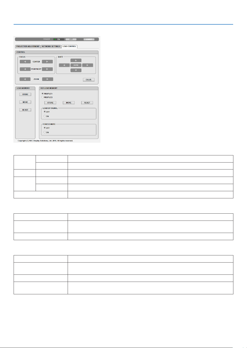
55
3. Convenient Features
LENS CONTROL
•CONTROL
FOCUS CENTER Alignthefocusaroundtheopticalaxis.
PERIPHERY Alignthefocusforthescreenperipheralarea.
ZOOM
◀/▶
Finelyadjustingthesizeofanimage.
SHIFT
▼▲◀▶
Adjusttheprojectedimage’sverticalandhorizontalposition.
HOME Returnthelensshiftpositiontothehomeposition.
CALIB. Correcttheadjustablezoom,focusandlesshiftrange.
•LENSMEMORY
STORE Storethecurrentadjustedvaluesinmemoryforeachinputsignal.
MOVE AppliestheadjustedvaluesofLENSSHIFT,motorizedZOOM,andmotorizedFO-
CUStothecurrentsignal.
RESET Returntheadjustedvaluedtothelastcondition.
•REF.LENSMEMORY
PROFILE1/PROFILE2 Selectastored[PROFILE]number.
STORE StoreeachadjustedvalueofLENSSHIFT,motorizedZOOMandmotorizedFOCUS
fortheselectedproleasthecommonvaluesforeveryinputsignal.
MOVE Movethelenstothestoredvaluesfortheselectedprole.
RESET Resetselected[REF.LENSMEMORY]fortheselected[PROFILE]tothedefault
factorysettings.
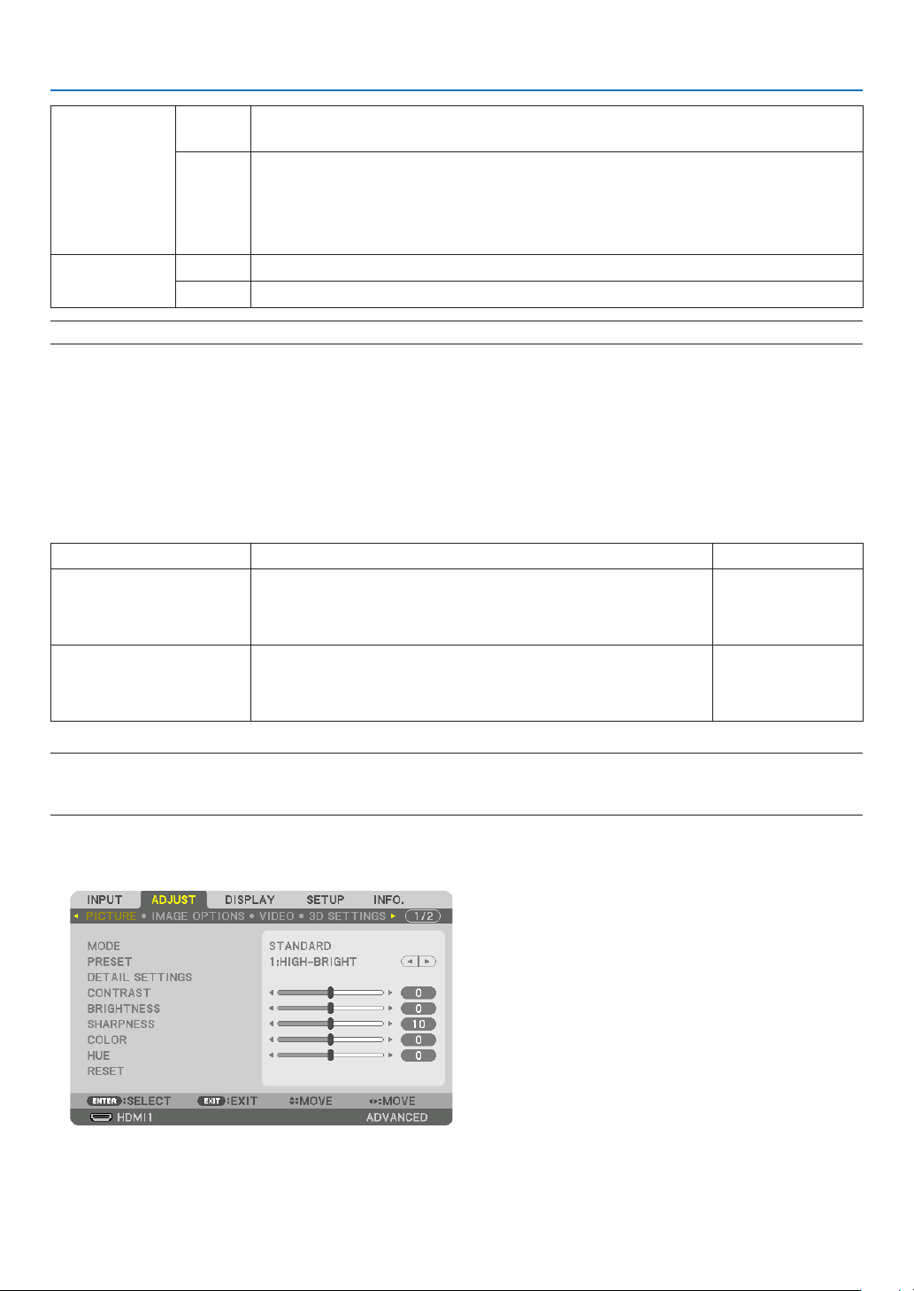
56
3. Convenient Features
LOADBY
SIGNAL
OFF Ifinputsignalisswitched,thelenswillnotshifttothelesshift,zoomandfocusval-
uesfortheselected[PROFILE]number.
ON Ifinputsignalisswitched,thelenswillshifttothevaluesfortheselected[PROFILE]
number.
Ifnoadjustedvalueshavebeenstoredto[LENSMEMORY],thelenswillapply
[REF.LENSMEMORY]adjustedvalues.Alternatively,ifnoadjustedvalueshave
beenstoredto[REF.LENSMEMORY],thelenswillstayunmoved.
FORCED
MUTE
OFF Notturnofftheimageduringlesshift.
ON Turnofftheimageduringlesshift.
NOTE:LENSMEMORYandREF.LENSMEMORYarefutureexpansionfunctions.
⓫ Storing Changes for Lens Shift, Zoom, and Focus [LENS
MEMORY]
ThisfunctionservestostoretheadjustedvalueswhenusingtheLENSSHIFT,motorizedZOOMandmotorizedFO-
CUSbuttonsoftheprojector.Adjustedvaluescanbeappliedtothesignalyouselected.Thiswilleliminatetheneed
toadjustlensshift,focus,andzoomatthetimeofsourceselection.Therearetwowaystosaveadjustedvaluesfor
lensshift,zoom,andfocus.
Functionname Description page
REF.LENSMEMORY Adjustedvaluescommontoallinputsignals.Atthetimeofinstallation,
twokindsofadjustedvaluescanbestored.
Ifnoadjustedvalueshavebeensavedto[LENSMEMORY],thelens
willapply[REF.LENSMEMORY]adjustedvalues.
→page117
LENSMEMORY Adjustedvaluesforeachinputsignal.
Usetheadjustedvaluesforthesignalwithadifferentaspectratioor
resolution.Theadjustedvaluescanbeappliedatthetimeofsource
selection.
→page99
NOTE:
• The[LENSMEMORY]featureisnotavailableforthelensunit,NP11FL/NP12ZL/NP13ZL/NP14ZL/NP30ZL.
• Besuretocarryout[LENSCALIBRATION]afterreplacingthelens.
To store your adjusted values in [REF. LENS MEMORY]:
1. Press the MENU button.
The menu will be displayed.
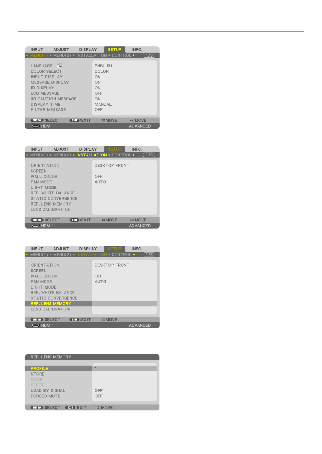
57
3. Convenient Features
2. Press the ▶buttontoselect[SETUP]andpresstheENTERbutton.
3. Press the ▶buttontoselect[INSTALLATION].
4. Press the ▼buttontoselect[REF.LENSMEMORY]andpresstheENTERbutton.
The [REF. LENS MEMORY] screen will be displayed.
5. Makesure[PROFILE]ishighlighted,thenpresstheENTERbutton.
The [PROFILE] selection screen appears.

58
3. Convenient Features
6. Pressthe▼/▲buttonstoselectthe[PROFILE]number,thenpresstheENTERbutton.
Return to the [REF. LENS MEMORY] settings screen.
7. Select[STORE]andpresstheENTERbutton.
The confirmation screen will be displayed.
8. Press the ◀buttontoselectand[YES]andpresstheENTERbutton.
Select a [PROFILE] number and save the adjusted [LENS SHIFT], [ZOOM], and [FOCUS] values to it.
9. Press the MENU button.
The menu will be closed.
TIP:
• Tostoreadjustedvaluesforeachinputsource,usetheLensMemoryfunction.(→ page 99)
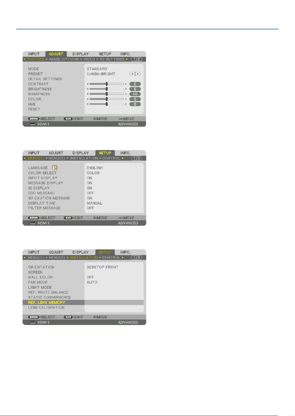
59
3. Convenient Features
To call up your adjusted values from [REF. LENS MEMORY]:
1. Press the MENU button.
The menu will be displayed.
2. Press the ▶buttontoselect[SETUP]andpresstheENTERbutton.
3. Press the ▶buttontoselect[INSTALLATION].
4. Press the ▼buttontoselect[REF.LENSMEMORY]andpresstheENTERbutton.
The [REF. LENS MEMORY] screen will be displayed.
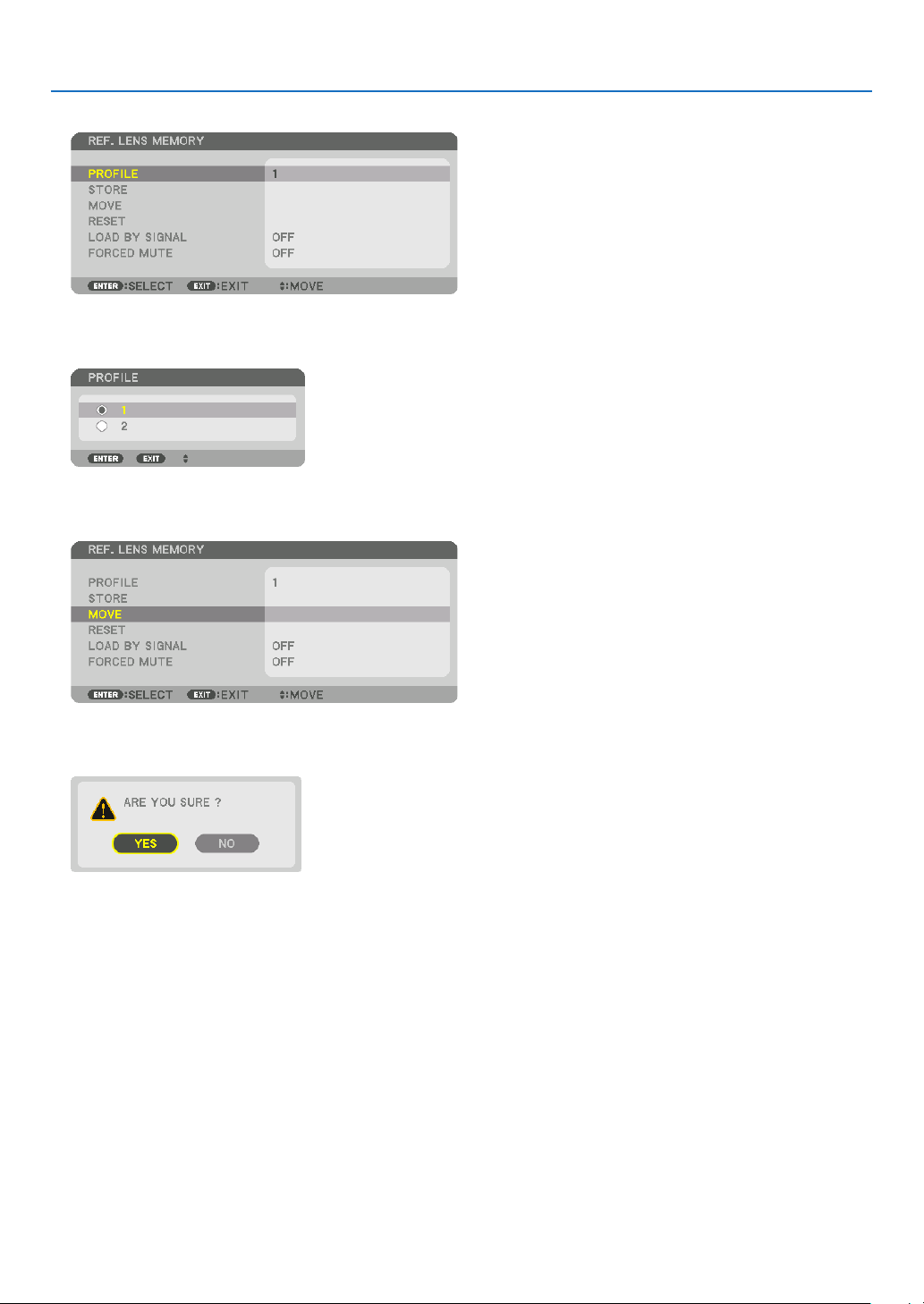
60
3. Convenient Features
5. Makesure[PROFILE]ishighlighted,thenpresstheENTERbutton.
The [PROFILE] selection screen appears.
6. Pressthe▼/▲buttonstoselectthe[PROFILE]number,thenpresstheENTERbutton.
Return to the [REF. LENS MEMORY] settings screen.
7. Select[MOVE]andpresstheENTERbutton.
The lens will shift based on the adjusted values stored in the selected [PROFILE].
8. Press the ◀buttontoselectand[YES]andpresstheENTERbutton.
The adjusted values will be applied to the current signal. .
9. Press the MENU button.
The menu will be closed.
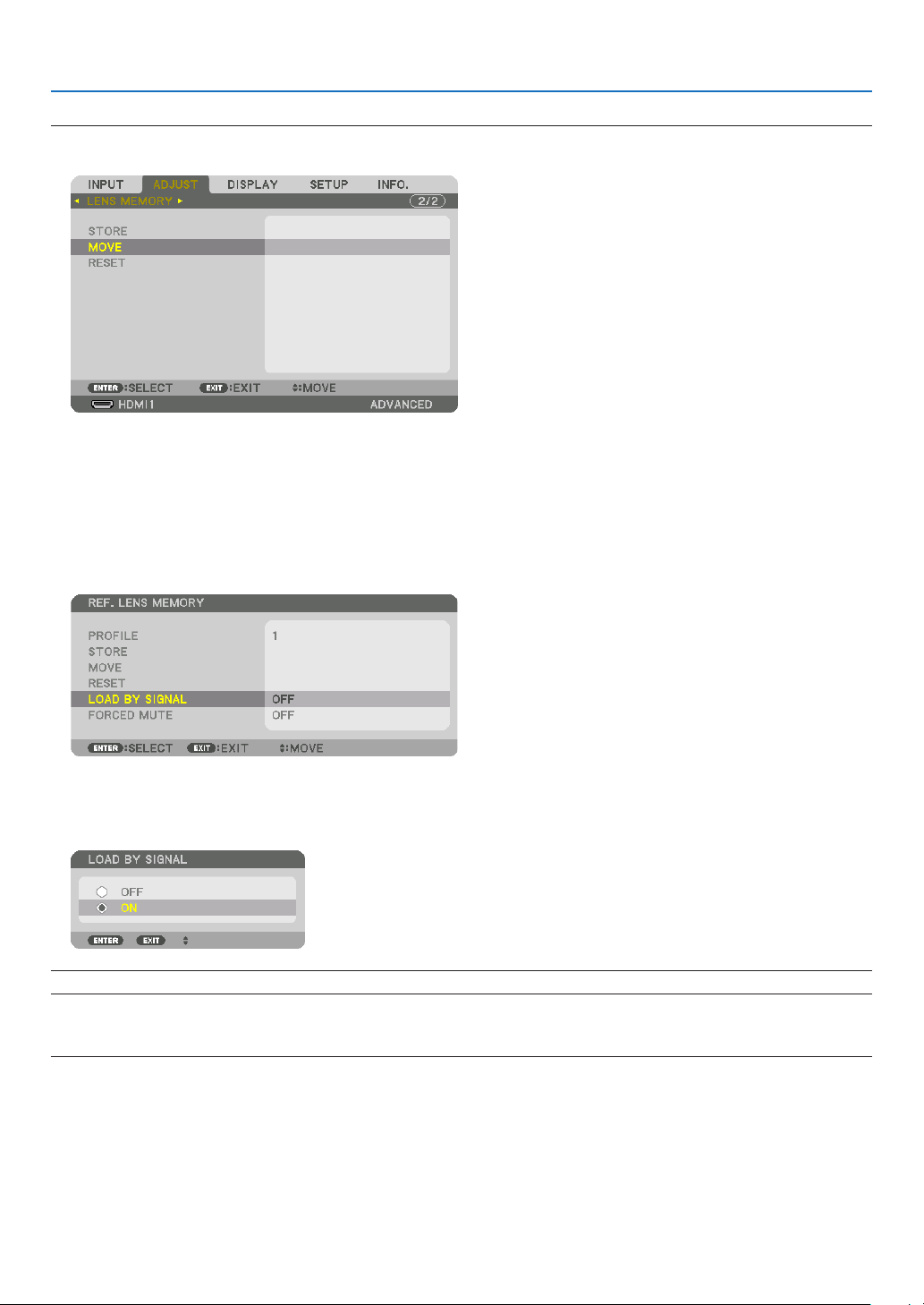
61
3. Convenient Features
TIP:
Tocallupthestoredvaluesfrom[LENSMEMORY]:
1. Fromthemenu,select[ADJUST]→[LENSMEMORY]→[MOVE]andpresstheENTERbutton.
The confirmation screen will be displayed.
2. Press the ◀buttontoselectand[YES]andpresstheENTERbutton.
During projection, if the adjusted values for an input signal have been saved, the lens will shift. If not, the lens will
shift according to the adjusted values stored in the selected [REF. LENS MEMORY] [PROFILE] number.
Toautomaticallyapplythestoredvaluesatthetimeofsourceselection:
1. Fromthemenu,select[SETUP]→[REF.LENSMEMORY]→[LOADBYSIGNAL]andpresstheENTERbutton.
2. Press the ▼buttontoselectand[ON]andpresstheENTERbutton.
This will move the lens automatically to the position at the time of source selection according to the adjusted
values.
NOTE:TheLensMemoryfunctionmaynotproduceacompletelyalignedimage(duetotolerancesinthelenses)usingtheadjusted
valuesstoredintheprojector.AftercallingupandapplyingthestoredvaluesfromtheLensMemoryfunction,nelyadjustthelens
shift, zoom and focus to produce the best possible image.
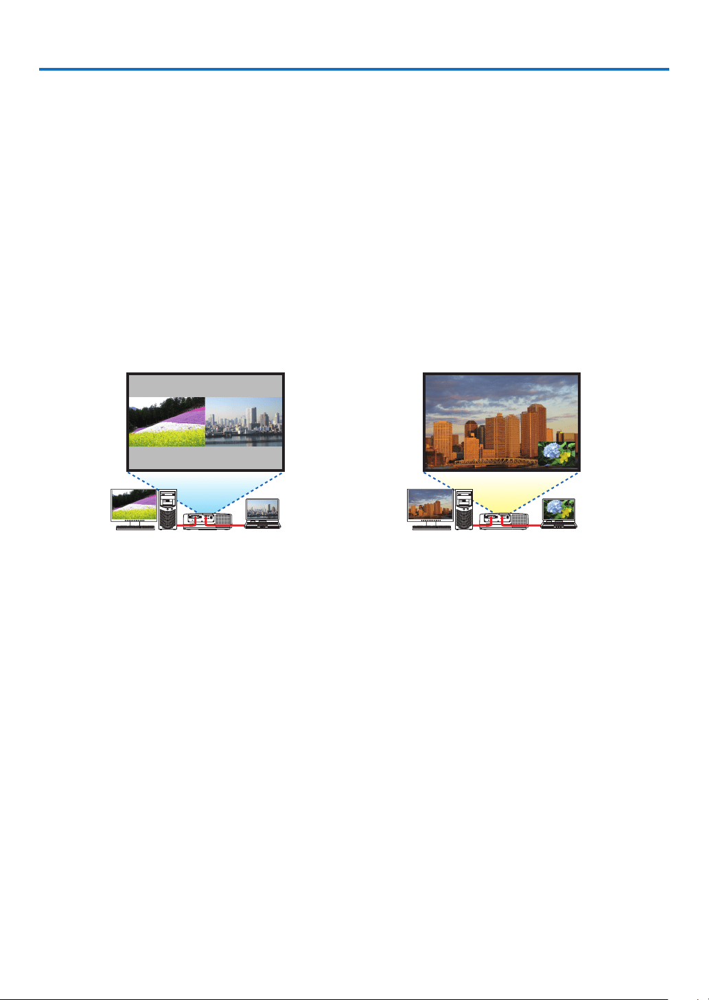
62
4. Multi-Screen Projection
❶ Things that can be done using multi-screen projection
Thisprojectorcanbeusedsinglyorarrangedinmultipleunitsformulti-screenprojection.
Wewillintroduceanexampleusingtwoprojectionscreenshere.
Case 1
Usingasingleprojectortoprojecttwotypesofvideosatthesametime
[PIP/PICTUREBYPICTURE]
Case 2
Usingfourprojectors(liquidcrystalpanel:WUXGA)toprojectvideowitharesolutionof3840×2160pixels
[TILING]
Case 1. Using a single projector to project two types of videos [PIP/PICTURE BY
PICTURE]
Connection example and projection image
In the case of [PICTURE BY PICTURE] In the case of [PIP]
On-screen menu operations
Display[DISPLAY]→[PIP/PICTUREBYPICTURE]→[MODE]screenintheon-screenmenuandselect[PIP]or
[PICTUREBYPICTURE].
Fordetails,pleasereferto“4-2DisplayingTwoPicturesattheSameTime”.(→page66)
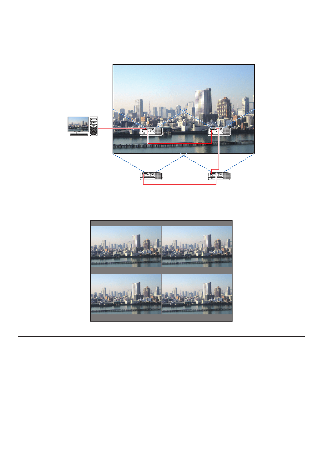
63
4. Multi-Screen Projection
Case 2. Using four projectors (liquid crystal panel: WUXGA) to project videos with a
resolution of 3840 × 2160 pixels [TILING]
Connection example and projection image
On-screen menu operations
1 Four similar videos are displayed when four projectors are projected.
Please request the retail store to adjust the projection position of each projector.
NOTE:
• Whensettinguptheprojector,assignauniquecontrolIDtoeachprojector.
• Setthe“Colorsetting”and“DeepColorsetting”onyourBlu-rayplayerorcomputerto“Auto”.Refertotheowner’smanualac-
companiedwithyourBlu-rayplayerorcomputerformoreinformation.
• ConnectanHDMIoutputofyourBlu-rayplayerorcomputertotherstprojectorandthenconnecttoHDBaseTIN/Ethernetport
of the second and subsequent projectors.
• SelectinganotherinputsourceonthesecondandsubsequentprojectorswilldisabletheHDBaseTrepeaterfunction.
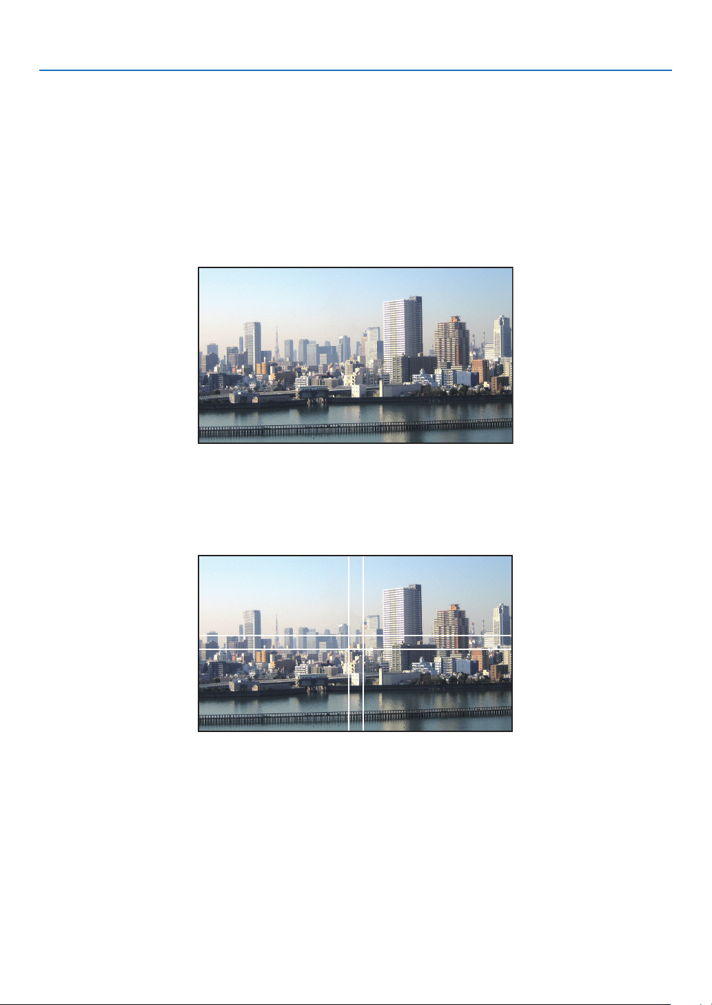
64
4. Multi-Screen Projection
2 Operatetheon-screenmenuusingthefourrespectiveprojectorstodividetheimageintofourportions.
Display [DISPLAY] → [MULTI SCREEN] → [PICTURE SETTING] Screen in the on-screen menu and select [TIL-
ING].
(1) In the screen for setting the number of horizontal units, select [2 UNITS]. (number of units in the horizontal
direction)
(2) In the screen for setting the number of vertical units, select [2 UNITS]. (number of units in the vertical direction)
(3) In the screen for setting the horizontal order, select [1st UNIT] or [2nd UNIT].
(look at the screens, the one on the left is the [1st UNIT] while the one on the right is the [2nd UNIT])
(4) In the screen for setting the vertical order, select the [1st UNIT] or the [2nd UNIT].
(look at the screens, the one at the top is the [1st UNIT] while the one at the bottom is the [2nd UNIT])
3 Adjust the lens shift of each projector to fine-tune the boundaries of the screen.
For further fine-tuning, adjust using [DISPLAY] → [EDGE BLENDING] in the on-screen menu for each projector.
For details, please refer to “4-3 Displaying a Picture Using [EDGE BLENDING]”.
(→ page 70)
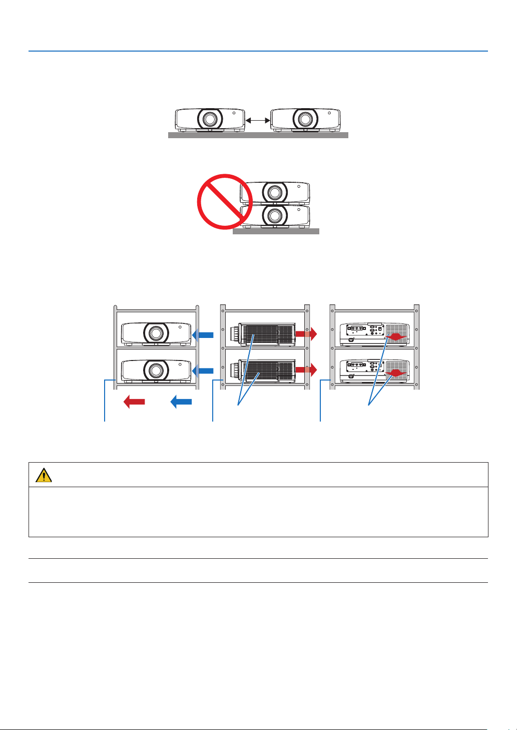
65
4. Multi-Screen Projection
Things to note when installing projectors
• Leavesufficientspaceontheleftandrightoftheprojectorsothattheintakeandexhaustventsoftheprojectorare
notobstructed.Whentheintakeandexhaustventsareobstructed,thetemperatureinsidetheprojectorwillrise
and this may result in a malfunction.
• Pleasedonotpileuptheprojectorsdirectlyontopofoneanotherwheninstallingthem.Whentheprojectorsare
piledupontopofoneanother,theymayfalldown,resultingindamageandfailure.
• Installationexamplewhenusingtwoprojectors
Thefollowinginstallationisrecommendedwhencombiningtheinstallationoftwoprojectorsformulti-screenprojec-
tion.Pleaseleaveaspaceofatleast10cmbetweenthetheintake/exhaustventandthewall.
[Installationexample]
Intake vent Exhaust vent
CabinetCabinetCabinet
Air dis-
charge
Air intake
Front Right side Back
WARNING
Pleaserequesttheretailstoreforspecialinstallationservicessuchaswhenmountingtheprojectortotheceiling.
Nevercarryouttheinstallationbyyourself.Theprojectormayfalldownandresultininjury.Pleaseuseasturdy
cabinetthatcanwithstandtheweightoftheprojectorfortheinstallation.Pleasedonotpileuptheprojectorsdirectly
on top of one another.
NOTE:
• Fortherangeoftheprojectiondistance,pleaserefertotheAppendix“Throwdistanceandscreensize”.(→ page 162)
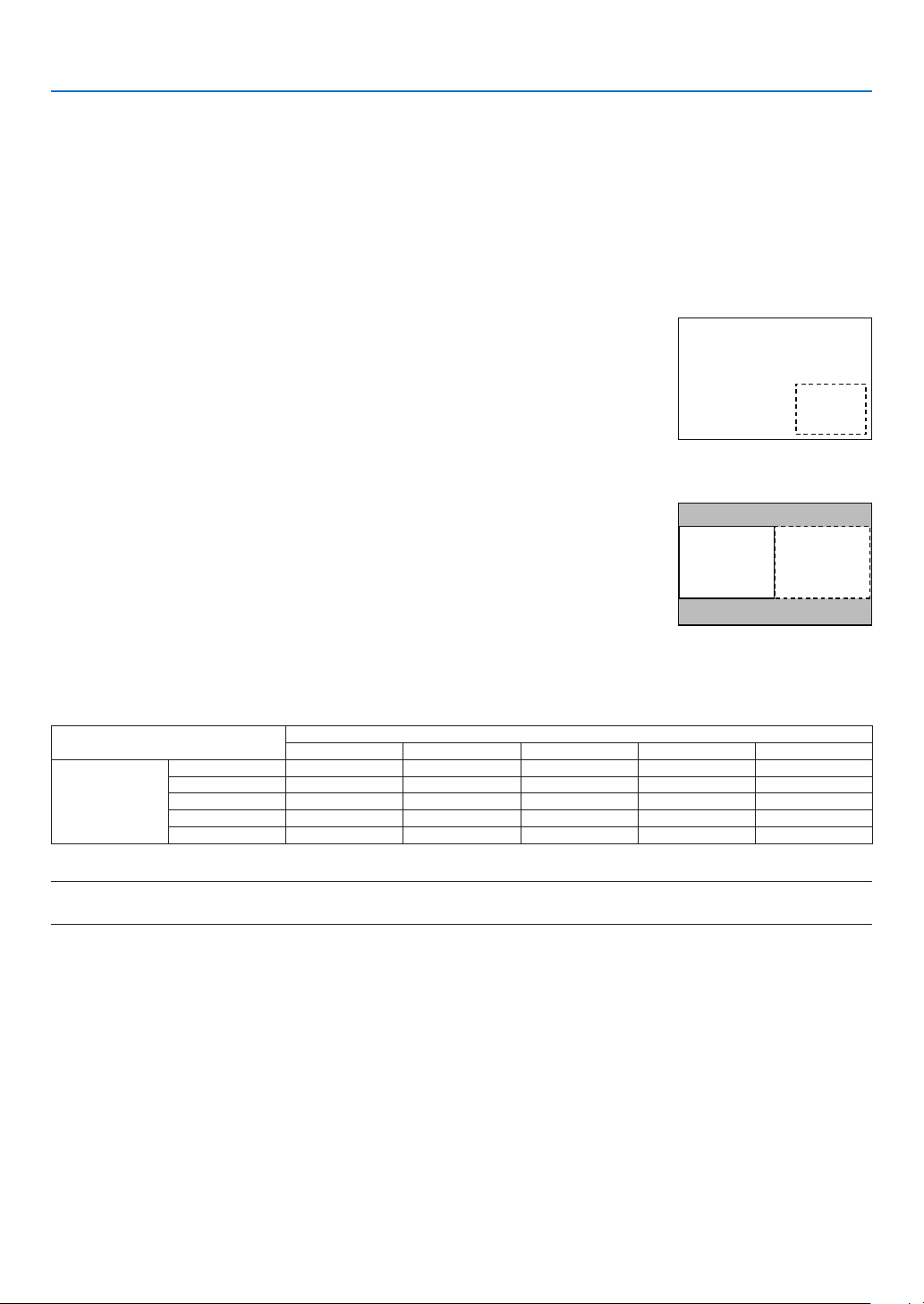
66
4. Multi-Screen Projection
❷ Displaying Two Pictures at the Same Time
Theprojectorhasafeaturethatallowsyoutoviewtwodifferentsignalssimultaneously.Youhavetwomodes:PIP
modeandPICTUREBYPICTUREmode.
Theprojectionvideointherstscreendisplayisknownasthemaindisplaywhiletheprojectionvideothatiscalled
outsubsequentlyisknownasthesub-display.
Selecttheprojectionfunctionunder[DISPLAY]→[PIP/PICTUREBYPICTURE]→[MODE]intheon-screenmenu
(thedefaultfactorysettingwhenshippedisPIP).(→page101)
• Asinglescreenisprojectedwhenpoweristurnedon.
Picture in Picture function
Asmallsub-displayisdisplayedinsidethemaindisplay.
Thesub-displaycanbesetupandadjustedasfollows.(→page101)
• Selectwhethertodisplaythesub-displayatthetopright,topleft,bottomright
orbottomleftofthescreen(thesizeofthesub-displaycanbeselectedand
thepositioncanbene-tuned)
• Switchthemaindisplaywiththesub-display
Main Display
Sub-Display
Picture by picture function
Displaythemaindisplayandsub-displaysidebyside.
Themaindisplayandsub-displaycanbesetupandadjustedasfollows.(→
page102)
• Selectingthedisplayboundary(ratio)ofthemaindisplayandsub-display
• Switchthemaindisplayandsub-display
Main Display Sub-Display
Input terminals that can be used for the main screen and sub-screen.
Themainscreenandsub-screencanprovidethefollowinginputterminals.
• Themaindisplayandsub-displaysupportcomputersignalsuptoWUXGA@60HzRB.
Sub-Display or additional display
HDMI1 HDMI2 DisplayPort COMPUTER HDBaseT
Main Display
HDMI1 No Yes Yes Yes Yes
HDMI2 Yes No Yes Yes Yes
DisplayPort Yes Yes No Yes Yes
COMPUTER Yes Yes Yes No Yes
HDBaseT Yes Yes Yes Yes No
NOTE:
• Somesignalsmaynotappeardependingontheresolution.
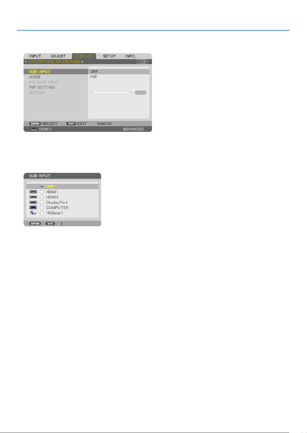
67
4. Multi-Screen Projection
Projecting two screens
1. PresstheMENUbuttontodisplaytheon-screenmenuandselect[DISPLAY]→[PIP/PICTUREBYPICTURE].
This displays the [PIP/PICTURE BY PICTURE] screen in the on-screen menu.
2. Select[SUBINPUT]usingthe▼/▲buttons,andpresstheENTERbutton.
This displays the [SUB INPUT] screen.
3. Selecttheinputsignalusingthe▼/▲buttons,andpresstheENTERbutton.
* This screen belongs to a HDBaseT model.
The [PIP] (PICTURE IN PICTURE) or [PICTURE BY PICTURE] screen set up under [MODE] is projected. (→
page 101)
• Whenthesignalnameisdisplayedingrey,thismeansthatitcannotbeselected.
• ThesignalcanalsobeselectedbypressingthePIPbuttonorPBP/POPbuttonontheremotecontrol.
4. Press the MENU button.
The on-screen menu will disappear.
5. Whenreturningtosinglescreen,displaythe[PIP/PICTUREBYPICTUE]screenonemoretimeandselect
[OFF]inthe[SUBINPUT]screenoftheStep3.
TIP:
• Duringdual-screenprojection,iftheselectedinputisnotsupportedbythesub-screen,thesub-screenwillappearasablack
screen.
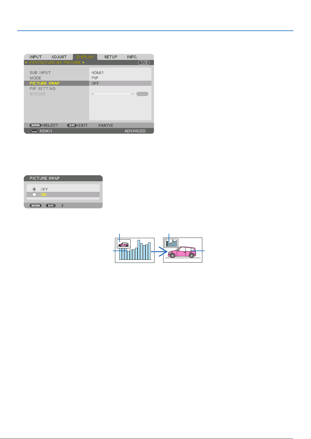
68
4. Multi-Screen Projection
Switching the main display with the sub-display and vice versa
1. PresstheMENUbuttontodisplaytheon-screenmenuandselect[DISPLAY]→[PIP/PICTUREBYPICTURE].
This displays the [PIP/PICTURE BY PICTURE] screen in the on-screen menu.
2. Select[PICTURESWAP]usingthe▼/▲buttonsandthenpresstheENTERbutton.
Display the screen for switching the display positions.
3. Select[ON]usingthe▼buttonandthenpresstheENTERbutton.
The video of the main display will switch with that of the sub-display.
When turned “OFF” When turned “ON”
Sub-display video
Main display video Sub-display video
Main display video
The signal output from the HDBaseT OUT/Ethernet terminal does not change even if the display positions are
switched.
4. Press the menu button.
The on-screen menu will disappear.

69
4. Multi-Screen Projection
Restrictions
• Thefollowingoperationsareenabledonlyforthemaindisplay.
• Audio-visualadjustments
• Videomagnication/compressionusingthepartialD-ZOOM/ZOOM+/−buttons.
However,magnication/compressionisuptothepositionssetin[PICTUREBYPICTUREBORDER]only.
• TESTPATTERN
• Thefollowingoperationsareenabledforboththemaindisplayandsub-display.Theseoperationscannotbeap-
plied individually.
• Momentarydeletionofvideo/audio
• Videopause
• [PIP/PICTUREBYPICTURE]cannotbeusedwhena3Dvideoisbeingdisplayed.
• Whenusingthe[PIP/PICTUREBYPICTURE]function,[DYNAMICCONTRAST]cannotbeused.
• [PIP/PICTUREBYPICTURE]cannotbeusedwhenthesignalinputhasaresolutionof1920×1200ormore.
• TheHDBaseTOUT/Ethernetporthasarepeaterfunction.Theoutputresolutionislimitedbythemaximumresolu-
tion of the connected monitor and projector.
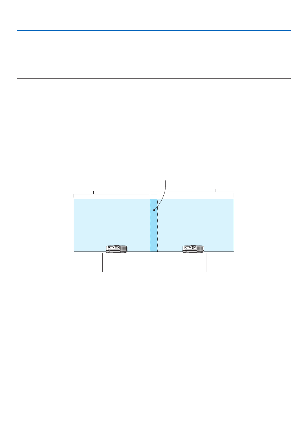
70
4. Multi-Screen Projection
❸ Displaying a Picture Using [EDGE BLENDING]
Ahighresolutionvideocanbeprojectedonanevenbiggerscreenbycombiningmultipleprojectorsontheleft,right,
top and bottom.
Thisprojectorisequippedwithan“EDGEBLENDINGFunction”thatmakestheedges(boundaries)oftheprojection
screenindistinguishable.
NOTE:
• Forprojectorthrowdistances,referto“Throwdistanceandscreensize”onpage162.
• BeforeperformingtheEdgeBlendingfunction,placetheprojectorinthecorrectpositionsothattheimagebecomessquarein
the appropriate size, and then make optical adjustments (lens shift, focus, and zoom).
• Adjustthebrightnessofeachprojectorusing[REF.LIGHT]under[LIGHTMODE].Inaddition,use[REF.WHITEBALANCE]to
adjustthe[CONTRAST],[BRIGHTNESS]and[UNIFORMITY].
Before explaining use of the Edge Blending function
Thissectionexplainsthecasefor“Example:Placingtwoprojectorssidebyside”.Asshown,theprojectedimageon
theleftisreferredtoas“ProjectorA”andtheprojectedimageontherightisreferredto“ProjectorB”.Unlessotherwise
speciedhereinafter,the“projector”isusedtomeanbothAandB.
Example: Placing two projectors side by side
Edge Blending area
Projected area
Projected area
Projector A Projector B
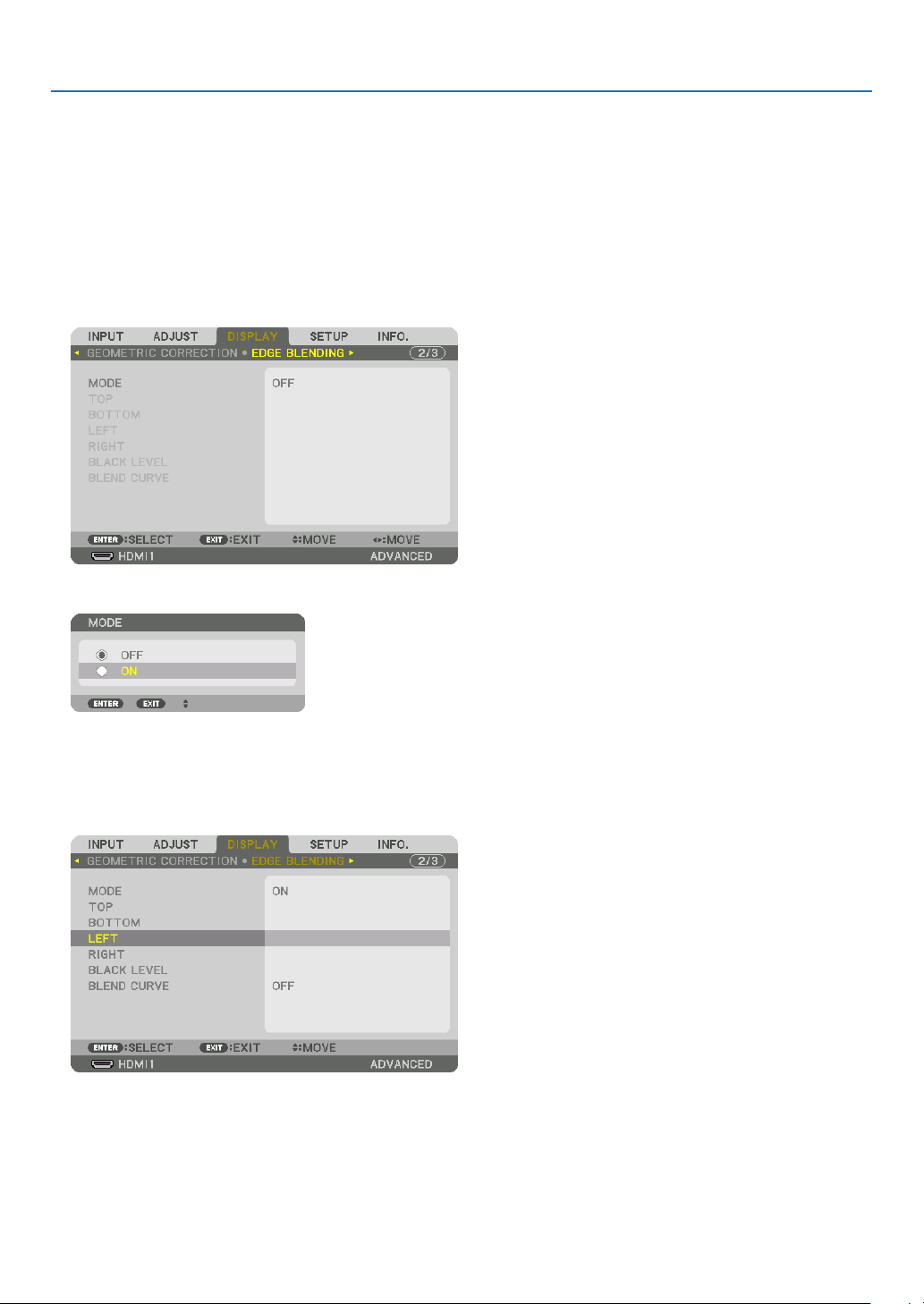
71
4. Multi-Screen Projection
Preparation:
• Turnontheprojectoranddisplayasignal.
• Whenperformingsettingsoradjustmentsusingoneremotecontrol,enablethe[CONTROLID]forassigningIDto
each projector so as not to activate the other projectors. (→page123)
Setting the overlap of projection screens
① Enable [EDGE BLENDING].
1 Pressthe“EdgeBlend.”button.
The [EDGE BLENDING] screen will be displayed. Align the cursor with [MODE] and then press the ENTER but-
ton. The mode screen will be displayed.
2 Select[MODE]→[ON]andpresstheENTERbutton.
This enables the Edge Blending function. The following menu items are available:
[TOP], [BOTTOM], [LEFT], [RIGHT], [BLACK LEVEL], and [BLEND CURVE]
3 Select[RIGHT]forProjectorAand[LEFT]forProjectorB.
Press the ENTER button.
The following items are available:
[CONTROL], [MARKER], [RANGE], and [POSITION]
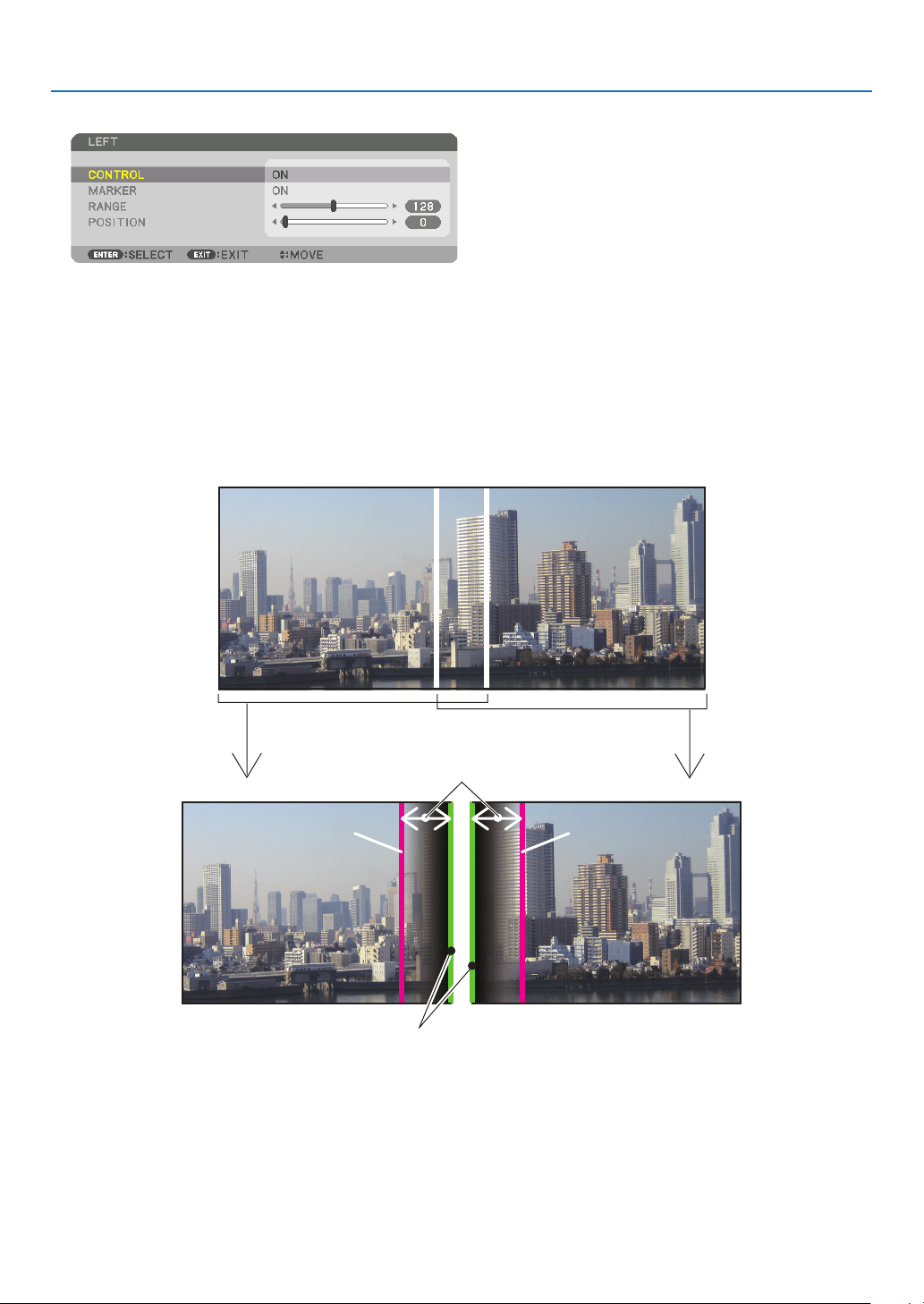
72
4. Multi-Screen Projection
4 Select[CONTROL]→[ON]andpresstheENTERbutton.
Each [TOP], [BOTTOM], [LEFT], [RIGHT], and [BLACK LEVEL] has its own [CONTROL], [MARKER], [RANGE],
and [POSITION].
• ForProjectorA,setthe[CONTROL]forthe[TOP],[LEFT]and[BOTTOM]to[OFF].SimilarlyforProjectorB,
set the [CONTROL] for the [TOP], [RIGHT] and [BOTTOM] to [OFF].
② Adjust [RANGE] and [POSITION] to determine an area of overlapped edges of images
projected from each projector.
Turningon[MARKER]willdisplaymarkersinmagentaandgreen.
Themagentamarkerisusedfor[RANGE]andgreenonefor[POSITION].
[RANGE]
(Determine an area of overlapped edges of
images.)
[POSITION]
(Determine the position of overlapped edges of images.)
Green marker
Turn on [RIGHT]
Magenta marker
Turn on [LEFT]
Magenta marker
* The2screensareseparatedinthediagramforexplanatorypurposes.
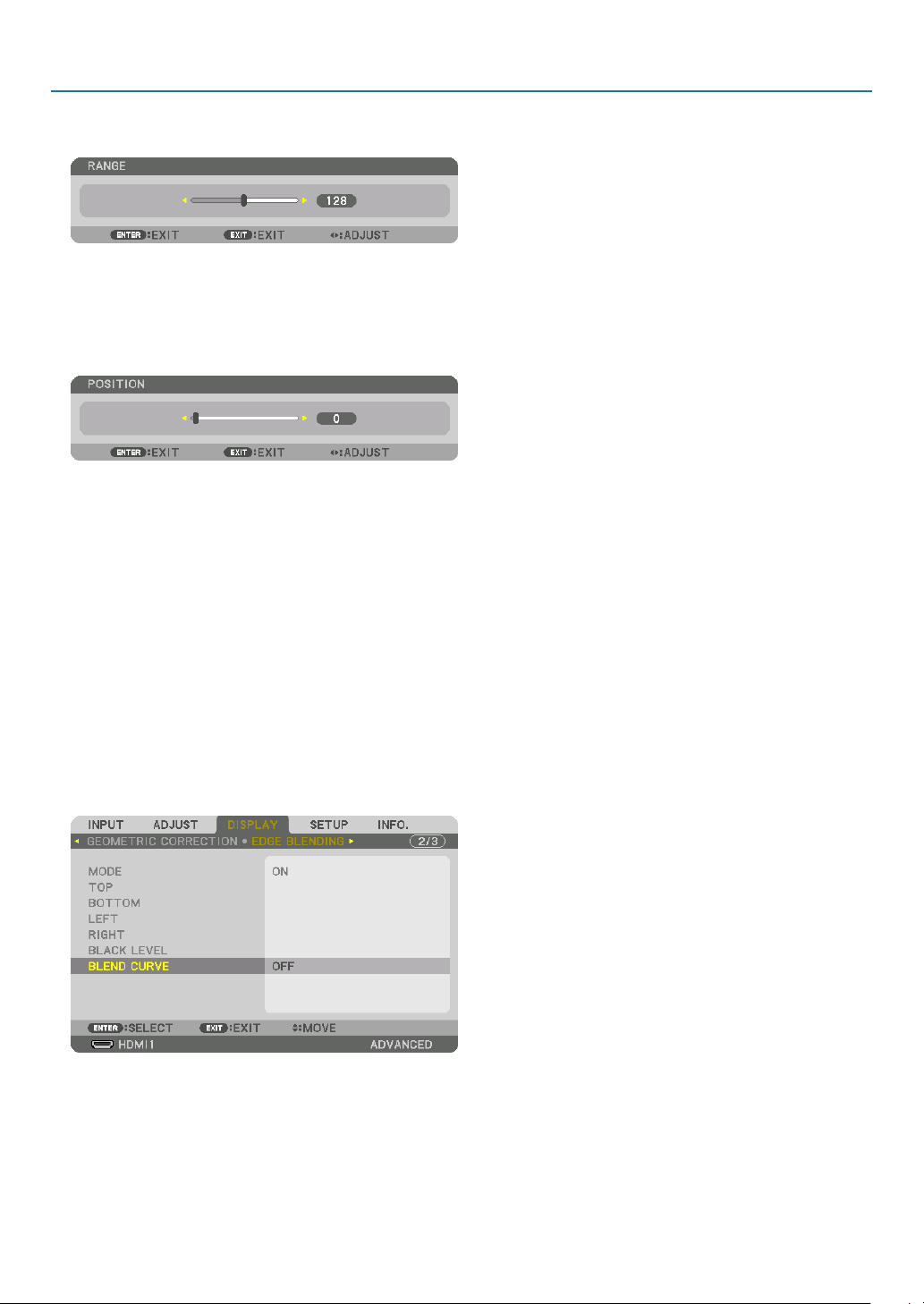
73
4. Multi-Screen Projection
1 Adjust[RANGE].
Use the ◀ or ▶ button to adjust the overlapped area.
TIP:
• Adjusttooverlaponeprojector’markerwiththeotherprojector’smarker.
2 Adjust[POSITION].
Use the ◀ or ▶ button to align one edge with the other edge of overlapped images.
TIP:
• Whendisplayingasignalwithadifferentresolution,performtheEdgeBlendingfunctionfromthestart.
• Settingof[MARKER]willnotbesavedandreturnto[OFF]whentheprojectoristurnedoff.
• Todisplayorhidethemarkerwhiletheprojectorisrunning,turnonoroff[MARKER]fromthemenu.
[BLEND CURVE]
Adjustthebrightnessoftheoverlappedsectiononthescreens.Accordingtothenecessity,adjustthebrightnessof
theoverlappedsectiononthescreensbythe[BLENDCURVE]AND[BLACKLEVEL].
• Setthe[MODE]to[ON]forselecting[BLENDCURVE]and[BLACKLEVEL].
Selectinganoptionforthe[BLENDCURVE]
Bycontrollingthegraduationoftheoverlappedsectiononthescreens,itmakestheborderontheprojectedscreens
inconspicuous.Selecttheoptimaloptionamongnine.
1. OntheOn-ScreenMenu,movethecursorontothe[DISPLAY]→[EDGEBLENDING]→[BLENDCURVE]and
thenpresstheENTER.Theoptionsettingscreenforthe[BRENDCURVE]isdisplayedon.
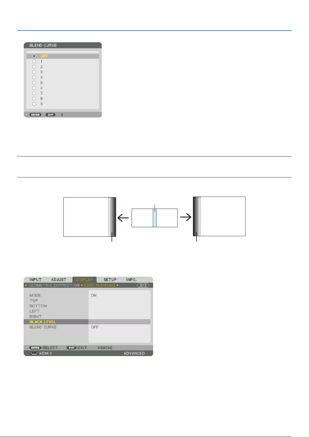
74
4. Multi-Screen Projection
2. Selectoneoptionamongnineby▲ or ▼.
Black Level Adjustment
Thisadjuststheblackleveloftheoverlappingareaandthenon-overlappingareaofthemulti-screen(EDGEBLENDING).
Adjustthebrightnesslevelifyoufeelthedifferenceistoolarge.
NOTE:
Thisfunctionisenabledonlywhen[MODE]isturnedon.
Adjustableareavariesdependingonwhatcombinationof[TOP],[BOTTOM],[LEFT]and[RIGHT]areturnedon.
Example: Adjusting the Black Level when placing two projectors side by side
Width of overlap
Adjust [CENTER] Adjust [CENTER]
Projector A’s
image
Projector B’s
image
Adjust [CENTER-RIGHT] Adjust [CENTER-LEFT]
1. Select[DISPLAY]→[EDGEBLENDING]→[BLACKLEVEL]andpresstheENTERbutton.
The screen will switch to the black level adjustment screen.
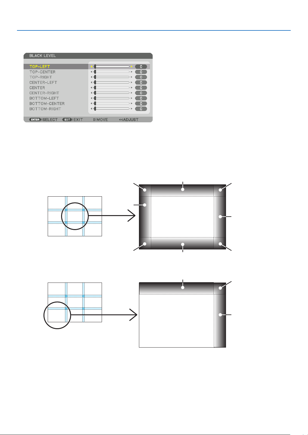
75
4. Multi-Screen Projection
2. Use the ▼ or ▲ button to select an item and use the ◀ or ▶toadjusttheblacklevel.
Do this for the other projector if necessary.
9-segmented portions for Black Level adjustment
Thecenterprojector
Thisfunctionadjuststhebrightnesslevelof9-segmentedportionsforthecenterprojectorand4-segmentedportions
for the left bottom projector as shown below.
TOP-LEFT
BOTTOM-LEFT
CENTER-
LEFT
TOP-RIGHT
CENTER-RIGHT
BOTTOM-RIGHT
TOP-CENTER
CENTER
CENTER
BOTTOM-CENTER
TOP-RIGHT
CENTER-RIGHT
TOP-CENTER
TIP:
• Thenumberofblackleveldivisionscreens(maximumofninedivisions)changesdependingonthenumberofedgeblending
positionsselected(top,bottom,right,left).Inaddition,whenthetop/bottomandleft/rightendsareselected,thecornerdivision
screen appears.
• Theedgeblendingwidthisthewidthsetintherangeandthecornerisformedbytheintersectingareaofthetop/bottomends
orleft/rightends.
• The[BLACKLEVEL]canbeadjustedtomakeitbrighteronly.
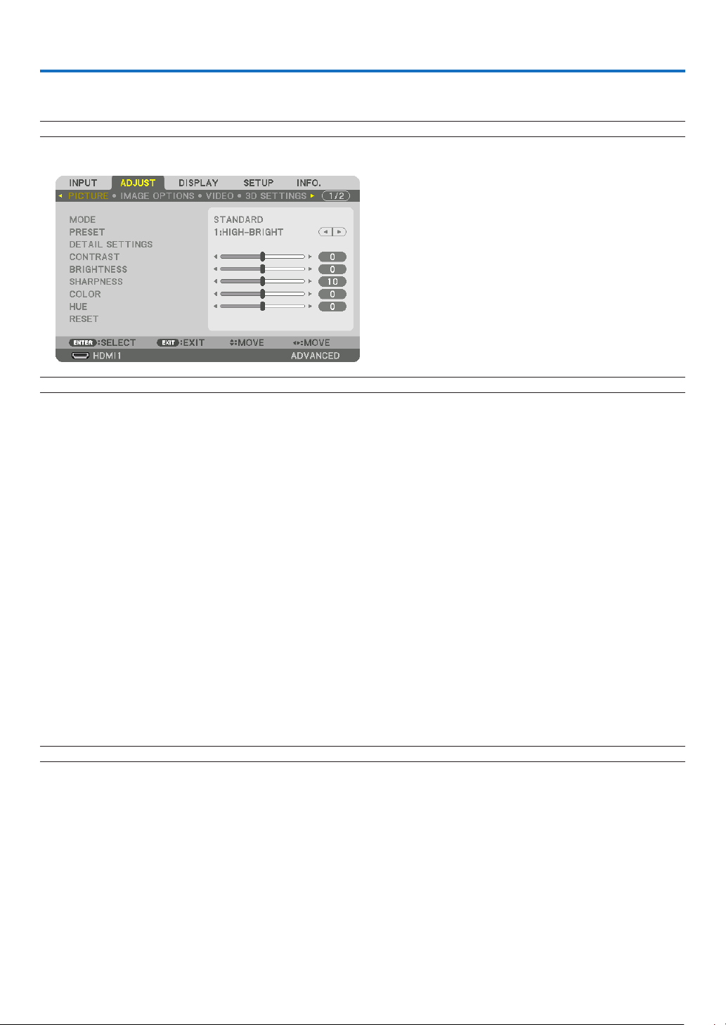
76
5. Using On-Screen Menu
❶ Using the Menus
NOTE: The on-screen menu may not be displayed correctly while interlaced motion video image is projected.
1. Press the MENU button on the remote control or the projector cabinet to display the menu.
NOTE: The commands such as ENTER,EXIT,▲▼, ◀▶ in the bottom show available buttons for your operation.
2. Press the ◀▶ buttons on the remote control or the projector cabinet to display the submenu.
3. PresstheENTERbuttonontheremotecontrolortheprojectorcabinettohighlightthetopitemorthefirst
tab.
4. Use the ▲▼ buttons on the remote control or the projector cabinet to select the item you want to adjust or
set.
Youcanusethe◀▶ buttons on the remote control or the projector cabinet to select the tab you want.
5. PresstheENTERbuttonontheremotecontrolortheprojectorcabinettodisplaythesubmenuwindow.
6. Adjustthelevelorturntheselecteditemonoroffbyusingthe▲▼◀▶ buttons on the remote control or the
projector cabinet.
Changes are stored until adjusted again.
7. Repeatsteps2-6toadjustanadditionalitem,orpresstheEXITbuttonontheremotecontrolortheprojector
cabinet to quit the menu display.
NOTE:Whenamenuormessageisdisplayed,severallinesofinformationmaybelost,dependingonthesignalorsettings.
8. Press the MENU button to close the menu.
Toreturntothepreviousmenu,presstheEXITbutton.
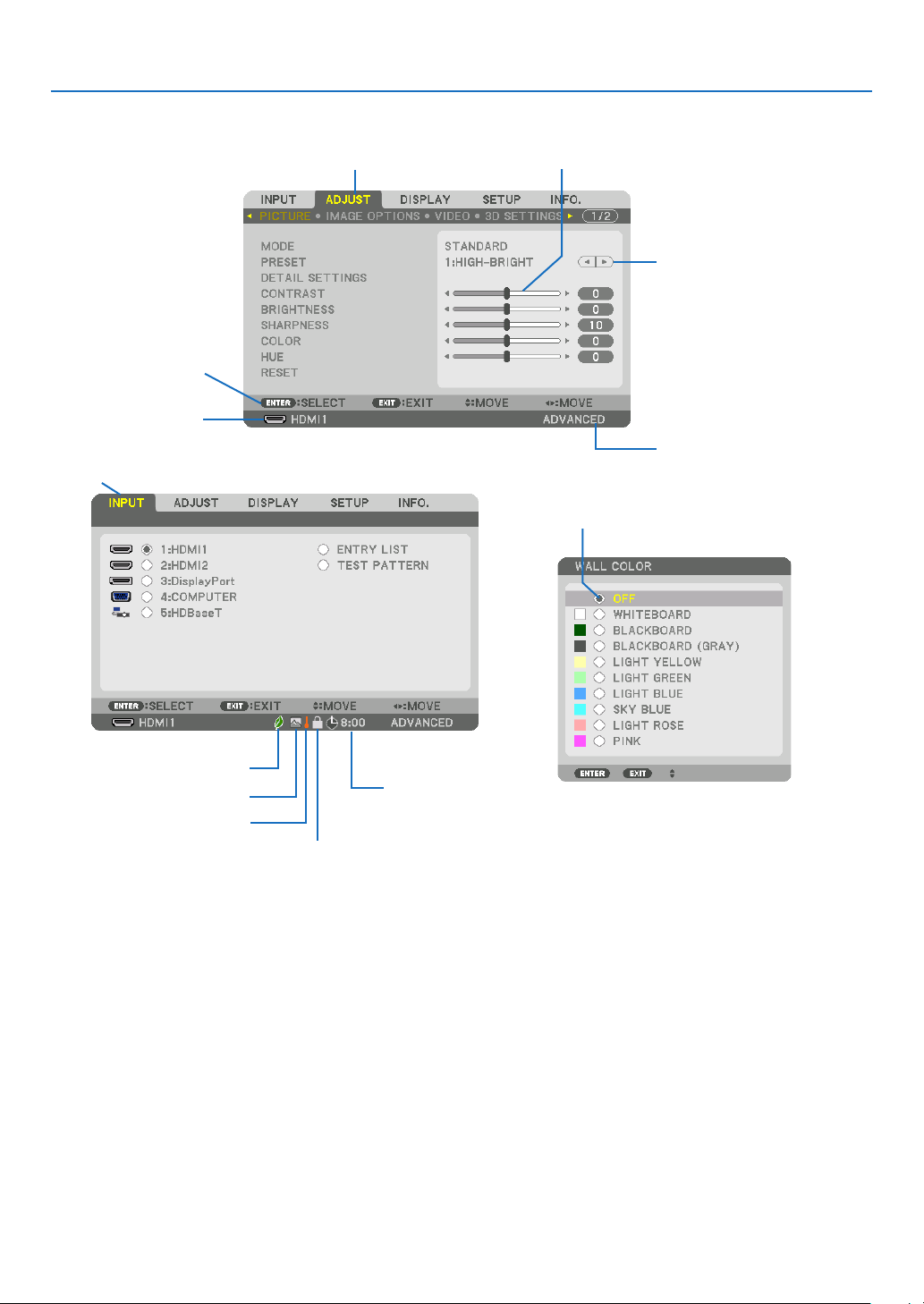
77
5. Using On-Screen Menu
❷
Menu Elements
Slide bar
Solid triangle
Menu mode
Ta b
Radio button
High Altitude symbol
ECO mode symbol
Menu windows or dialog boxes typically have the following elements:
Highlight ����������������������������� Indicates the selected menu or item�
Solid triangle ����������������������Indicates further choices are available� A highlighted triangle indicates the item is active�
Tab ��������������������������������������Indicates a group of features in a dialog box� Selecting on any tab brings its page to the front�
Radio button ����������������������� Use this round button to select an option in a dialog box�
Source ��������������������������������Indicates the currently selected source�
Menu mode ������������������������Indicates the current menu mode: BASIC or ADVANCED�
Off Timer remaining time ���� Indicates the remaining countdown time when the [OFF TIMER] is preset�
Slide bar �����������������������������Indicates settings or the direction of adjustment�
ECO mode symbol ��������������Indicates [ECO MODE] is set�
Key Lock symbol ����������������Indicates the [CONTROL PANEL LOCK] is enabled�
Thermometer symbol ���������Indicates the [ECO MODE] is forcibly set to [ON] mode because the internal temperature is too high�
High Altitude symbol ����������Indicates the [FAN MODE] is set to [HIGH ALTITUDE] mode�
Source
Available buttons
Thermometer symbol
Key Lock symbol
Off Timer remaining
time
Highlight
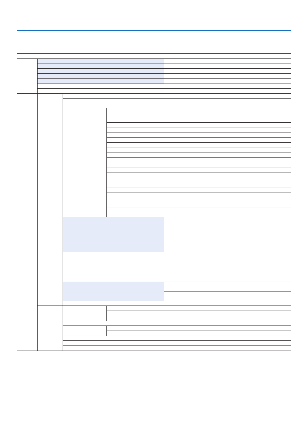
78
5. Using On-Screen Menu
* Theasterisk(*)indicatesthatthedefaultsettingvariesdependingonthesignal.
*1 The[GAMMACORRECTION]itemisavailablewhenanitemotherthan[DICOMSIM.]isselectedfor[REFERENCE].
*2 The[SCREENSIZE]itemisavailablewhen[DICOMSIM.]isselectedfor[REFERENCE].
*3 When[PRESENTATION]or[HIGH-BRIGHT]isselectedin[REFERENCE],the[COLORTEMPERATURE]isnotavailable.
*4 The[INPUTRESOLUTION]itemcanbeselectedforCOMPUTERinput.
*5 The[HDRMODE]itemisavailableexclusivelyfor4Ksignal.
•Basicmenuitemsareindicatedbyshadedarea.
❸ List of Menu Items
Somemenuitemsarenotavailabledependingontheinputsource.
Menu Item Default Options
INPUT
1:HDMI1 *
2:HDMI2 *
3:DisplayPort *
4:COMPUTER *
5:HDBaseT
ENTRY LIST
TEST PATTERN
ADJUST
PICTURE
MODE STANDARD STANDARD, PROFESSIONAL
PRESET *
HIGH-BRIGHT, PRESENTATION, VIDEO, MOVIE, GRAPHIC, sRGB,
DICOM SIM�
DETAIL SETTINGS
GENERAL
REFERENCE *
AUTO, HIGH-BRIGHT, PRESENTATION, VIDEO, MOVIE, GRAPHIC,
sRGB, DICOM SIM�
GAMMA CORRECTION*
1
DYNAMIC, NATURAL, BLACK DETAIL
SCREEN SIZE*
2
* LARGE, MEDIUM, SMALL
COLOR TEMPERATURE*
3
*
DYNAMIC CONTRAST * OFF, MOTION IMAGE, STILL IMAGE
LIGHT ADJUST *
WHITE BALANCE
CONTRAST R 0
CONTRAST G 0
CONTRAST B 0
BRIGHTNESS R 0
BRIGHTNESS G 0
BRIGHTNESS B 0
COLOR CORRECTION
RED 0
GREEN 0
BLUE 0
YELLOW 0
MAGENTA 0
CYAN 0
CONTRAST 50
BRIGHTNESS 50
SHARPNESS 10
COLOR 50
HUE 0
VOLUME
RESET
IMAGE
OPTIONS
CLOCK *
PHASE *
HORIZONTAL *
VERTICAL *
BLANKING * TOP, BOTTOM, LEFT, RIGHT
OVERSCAN AUTO, 0[%], 5[%], 10[%]
ASPECT RATIO
AUTO
(COMPUTER) AUTO, NORMAL, 4:3, 5:4, 16:9, 15:9, 16:10, FULL,
NATIVE
AUTO
(HDTV/SDTV) AUTO, NORMAL, 4:3, LETTERBOX, WIDE SCREEN,
ZOOM, FULL
INPUT RESOLUTION*
4
* –
VIDEO
NOISE REDUCTION
RANDOM NR * OFF, LOW, MEDIUM, HIGH
MOSQUITO NR OFF OFF, LOW, MEDIUM, HIGH
BLOCK NR OFF OFF, LOW, MEDIUM, HIGH
DEINTERLACE NORMAL NORMAL, MOVIE, STILL
CONTRAST
ENHANCEMENT
MODE AUTO OFF, AUTO, NORMAL
GAIN
SIGNAL TYPE AUTO AUTO, RGB, REC601, REC709, REC2020
VIDEO LEVEL AUTO AUTO, NORMAL, ENHANCED, SUPER WHITE
HDR MODE*
5
AUTO AUTO, OFF, ON

79
5. Using On-Screen Menu
Menu Item Default Options
ADJUST
3D SETTINGS
STEREO VIEWER SINGLE SINGLE, DUAL LEFT, DUAL RIGHT
STEREO FILTER SINGLE SINGLE, DUAL LEFT, DUAL RIGHT
FORMAT AUTO
AUTO, OFF(2D), FRAME PACKING, SIDE BY SIDE(HALF), SIDE
BY SIDE(FULL), TOP AND BOTTOM, FRAME ALTERNATIVE, LINE
ALTERNATIVE
L/R INVERT OFF OFF, ON
LENS
MEMORY
STORE
MOVE
RESET
DISPLAY
PIP/PICTURE
BY PICTURE
SUB INPUT OFF OFF, HDMI1, HDMI2, DisplayPort, COMPUTER, HDBaseT
MODE PIP PIP, PICTURE BY PICTURE
PICTURE SWAP OFF OFF, ON
PIP SETTING
START POSITION TOP-LEFT TOP-LEFT, TOP-RIGHT, BOTTOM-LEFT, BOTTOM-RIGHT
HORIZONTAL POSITION
VERTICAL POSITION
SIZE MEDIUM LARGE, MEDIUM, SMALL
BORDER
GEOMETRIC
CORRECTION
MODE OFF
OFF, KEYSTONE, CORNERSTONE, HORIZONTAL CORNER,
VERTICAL CORNER, WARP, PC TOOL
KEYSTONE
HORIZONTAL
VERTICAL
TILT
THROW RATIO
CORNERSTONE
TOP-LEFT, TOP, TOP-RIGHT, LEFT, RIGHT, BOTTOM-LEFT,
BOTTOM, BOTTOM-RIGHT
HORIZONTAL CORNER
TOP-LEFT, TOP, TOP-RIGHT, LEFT, RIGHT, BOTTOM-LEFT,
BOTTOM, BOTTOM-RIGHT
VERTICAL CORNER
TOP-LEFT, TOP, TOP-RIGHT, LEFT, RIGHT, BOTTOM-LEFT,
BOTTOM, BOTTOM-RIGHT
WARP
TOP-LEFT, TOP, TOP-RIGHT, LEFT, RIGHT, BOTTOM-LEFT,
BOTTOM, BOTTOM-RIGHT
PC TOOL OFF OFF, 1, 2, 3
RESET
EDGE
BLENDING
MODE OFF OFF, ON
TOP
CONTROL ON OFF, ON
MARKER OFF OFF, ON
RANGE
POSITION
BOTTOM
CONTROL ON OFF, ON
MARKER OFF OFF, ON
RANGE
POSITION
LEFT
CONTROL ON OFF, ON
MARKER OFF OFF, ON
RANGE
POSITION
RIGHT
CONTROL ON OFF, ON
MARKER OFF OFF, ON
RANGE
POSITION
BLACK LEVEL
TOP-LEFT
TOP-CENTER
TOP-RIGHT
CENTER-LEFT
CENTER
CENTER-RIGHT
BOTTOM-LEFT
BOTTOM-CENTER
BOTTOM-RIGHT
BLEND CURVE 5 OFF, 1, 2, 3, 4, 5, 6, 7, 8, 9
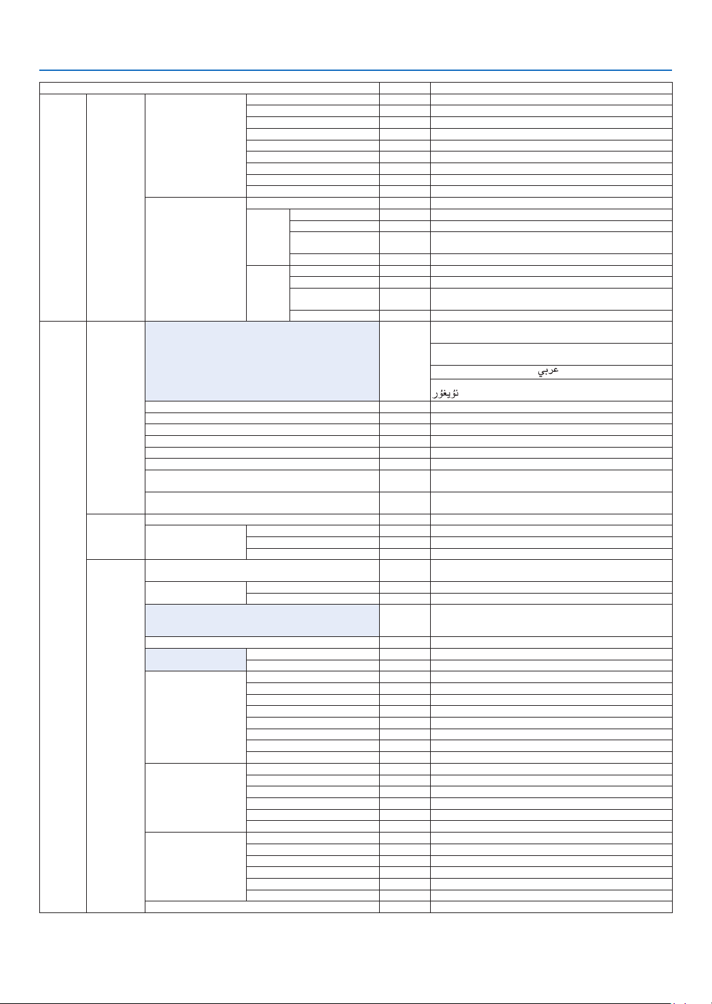
80
5. Using On-Screen Menu
Menu Item Default Options
DISPLAY
MULTI
SCREEN
WHITE BALANCE
MODE OFF OFF, ON
CONTRAST W
CONTRAST R
CONTRAST G
CONTRAST B
BRIGHTNESS W
BRIGHTNESS R
BRIGHTNESS G
BRIGHTNESS B
PICTURE SETTING
MODE OFF OFF, ZOOM, TILING
ZOOM
HORIZONTAL ZOOM
VERTICAL ZOOM
HORIZONTAL
POSITION
VERTICAL POSITION
TILING
WIDTH 1 UNIT, 2 UNITS, 3 UNITS, 4 UNITS
HEIGHT 1 UNIT, 2 UNITS, 3 UNITS, 4 UNITS
HORIZONTAL
POSITION
1st UNIT, 2nd UNIT, 3rd UNIT, 4th UNIT
VERTICAL POSITION 1st UNIT, 2nd UNIT, 3rd UNIT, 4th UNIT
SETUP
MENU(1)
LANGUAGE ENGLISH
ENGLISH, DEUTSCH, FRANÇAIS, ITALIANO, ESPAÑOL, SVENSKA,
日本語
DANSK, PORTUGUÊS, ČEŠTINA, MAGYAR, POLSKI,
NEDERLANDS, SUOMI
NORSK, TÜRKÇE, РУССКИЙ,
, Ελληνικά, 简体中文, 한국어
ROMÂNĂ, HRVATSKA, БЪЛГАРСКИ, INDONESIA, , ไทย,
, 繁體中文, Tiếng Việt
COLOR SELECT COLOR COLOR, MONOCHROME
INPUT DISPLAY ON OFF, ON
MESSAGE DISPLAY ON OFF, ON
ID DISPLAY ON OFF, ON
ECO MESSAGE OFF OFF, ON
3D CAUTION MESSAGE ON OFF, ON
DISPLAY TIME
AUTO 45
SEC
MANUAL, AUTO 5 SEC, AUTO 15 SEC, AUTO 45 SEC
FILTER MESSAGE OFF
OFF, 100[H], 500[H], 2000[H], 4000[H], 5000[H], 6000[H],
7000[H], 10000[H]
MENU(2)
MENU ANGLE 0°, 90°, 270°
MENU POSITION
HORIZONTAL POSITION
VERTICAL POSITION
RESET
INSTALLATION
ORIENTATION AUTO
AUTO, DESKTOP FRONT, CEILING REAR, DESKTOP REAR,
CEILING FRONT
SCREEN
SCREEN TYPE FREE FREE, 4:3 SCREEN, 16:9 SCREEN, 16:10 SCREEN
POSITION
WALL COLOR OFF
OFF, WHITEBOARD, BLACKBOARD, BLACKBOARD (GRAY), LIGHT
YELLOW, LIGHT GREEN, LIGHT BLUE, SKY BLUE, LIGHT ROSE,
PINK
FAN MODE AUTO AUTO, NORMAL, HIGH, HIGH ALTITUDE
LIGHT MODE
ECO MODE OFF OFF, ON
REF� LIGHT ADJUST
REF� WHITE BALANCE
CONTRAST R
CONTRAST G
CONTRAST B
BRIGHTNESS R
BRIGHTNESS G
BRIGHTNESS B
UNIFORMITY R
UNIFORMITY B
STATIC CONVERGENCE
HORIZONTAL R
HORIZONTAL G
HORIZONTAL B
VERTICAL R
VERTICAL G
VERTICAL B
REF� LENS MEMORY
PROFILE 1 1, 2
STORE
MOVE
RESET
LOAD BY SIGNAL OFF OFF, ON
FORCED MUTE OFF OFF, ON
LENS CALIBRATION
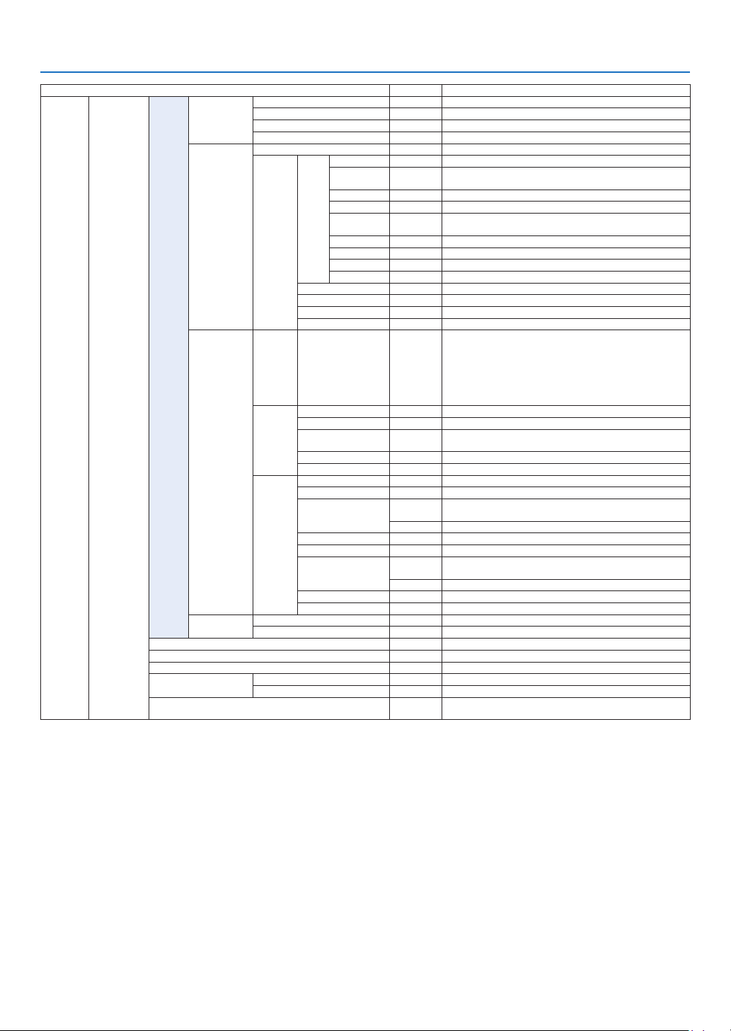
81
5. Using On-Screen Menu
Menu Item Default Options
SETUP CONTROL
TOOLS
ADMINISTRA-
TOR MODE
MENU MODE ADVANCED ADVANCED, BASIC
NOT SAVE SETTING VALUES OFF OFF, ON
NEW PASSWORD
CONFIRM PASSWORD
PROGRAM
TIMER
ENABLE OFF OFF, ON
SETTINGS
EDIT
ACTIVE OFF, ON
DAY
SUN, MON, TUE, WED, THU, FRI, SAT, MON-FRI, MON-SAT,
EVERY DAY
TIME
FUNCTION POWER, INPUT, ECO MODE
ADVANCED
SETTINGS
POWER OFF, ON
SOURCE HDMI1, HDMI2, DisplayPort, COMPUTER, HDBaseT
ECO MODE OFF, ON
REPEAT OFF, ON
DELETE
UP
DOWN
BACK
DATE AND TIME
SETTINGS
TIME
ZONE
SETTIMGS
UTC
-12:00, -11:30, -11:00, -10:30, -10:00, -09:30, -09:00, -08:30,
-08:00, -07:30, -07:00, -06:30, -06:00, -05:30, -05:00, -04:30,
-04:00, -03:30, -03:00, -02:30, -02:00, -01:30, -01:00, -00:30,
00:00, +00:30, +01:00, +01:30, +02:00, +02:30, +03:00, +03:30,
+04:00, +04;30, +05:00, +05:30, +06:00, +06:30, +07:00, +07:30,
+08:00, +08:30, +09:00, +09:30, +10:00, +10:30, +11:00, +11:30,
+12:00, +12:30, +13:00
DATE
AND TIME
SETTINGS
DATE MM/DD/YYYY
TIME HH:MM
INTERNET TIME
SERVER
OFF, ON
IP ADDRESS
UPDATE
SUMMER
TIME
SETTINGS
ENABLE OFF, ON
MON(START) 1, 2, 3, 4, 5, 6, 7, 8, 9, 10, 11, 12
DAY(START)
FIRST WEEK, SECOND WEEK, THIRD WEEK, FOURTH WEEK, LAST
WEEK
SUN, MON, TUE, WED, THU, FRI, SAT
TIME(START)
MON(EXIT) 1, 2, 3, 4, 5, 6, 7, 8, 9, 10, 11, 12
DAY(EXIT)
FIRST WEEK, SECOND WEEK, THIRD WEEK, FOURTH WEEK, LAST
WEEK
SUN, MON, TUE, WED, THU, FRI, SAT
TIME(EXIT)
TIME DIFFERENCE +01:00, +00:30, -00:30, -01:00
MOUSE
BUTTON RIGHT HAND RIGHT HAND, LEFT HAND
SENSITIVITY MEDIUM FAST, MEDIUM, SLOW
CONTROL PANEL LOCK OFF OFF, ON
SECURITY OFF OFF, ON
COMMUNICATION SPEED 38400bps 4800bps, 9600bps, 19200bps, 38400bps, 115200bps
CONTROL ID
CONTROL ID NUMBER 1 1–254
CONTROL ID OFF OFF, ON, AUTO
REMOTE SENSOR
FRONT/
BACK
FRONT/BACK, FRONT, BACK, HDBase-T
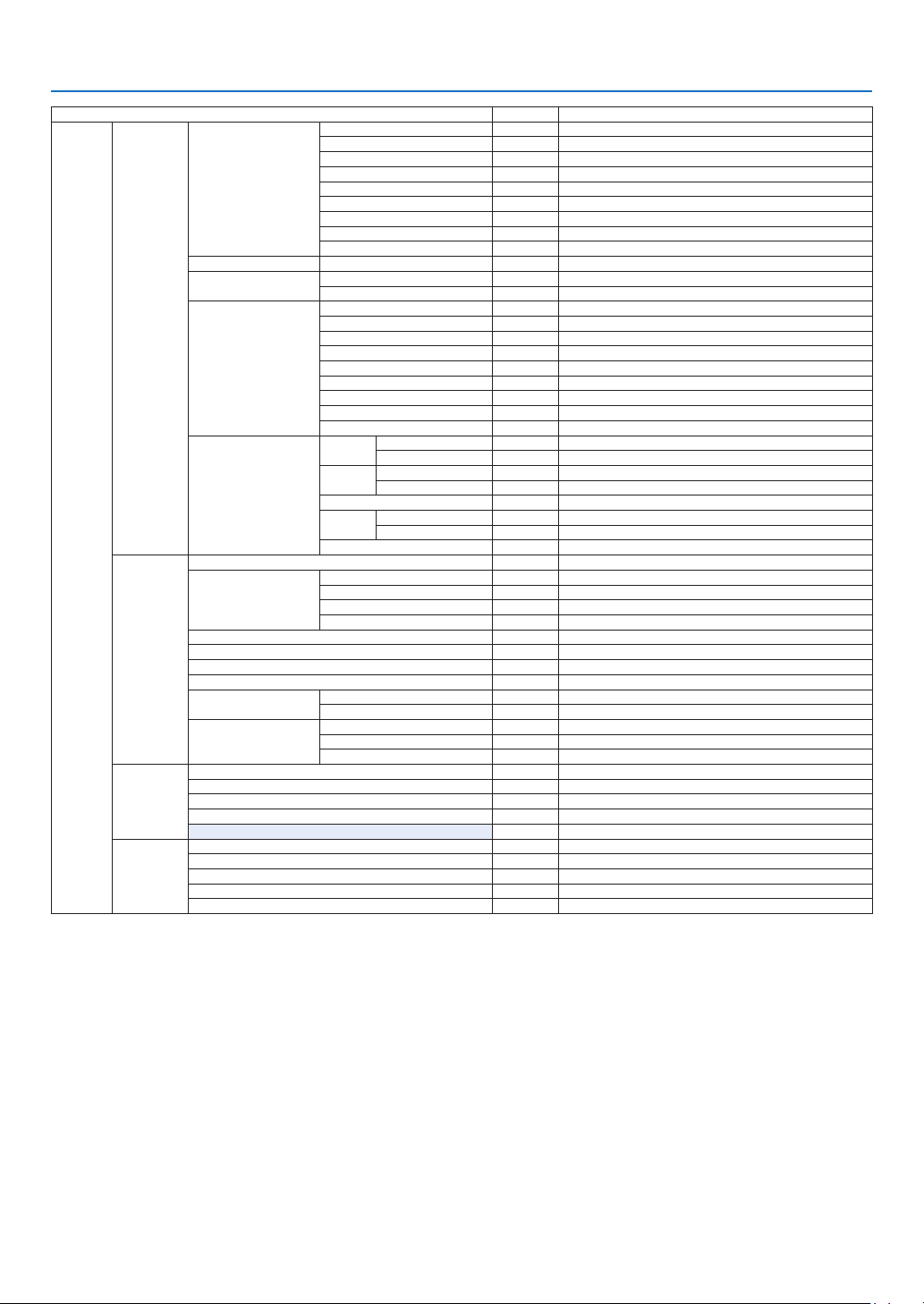
82
5. Using On-Screen Menu
Menu Item Default Options
SETUP
NETWORK
SETTINGS
WIRED LAN
INTERFACE LAN, HDBaseT
PROFILES DISABLE, PROFILE 1, PROFILE 2
DHCP OFF, ON
IP ADDRESS
SUBNET MASK
GATEWAY
AUTO DNS OFF, ON
DNS CONFIGURATION
RECONNECT
PROJECTOR NAME PROJECTOR NAME PJ-********
DOMAIN
HOST NAME pj-********
DOMAIN NAME
ALERT MAIL
ALERT MAIL OFF, ON
HOST NAME
DOMAIN NAME
SENDER'S ADDRESS
SMTP SERVER NAME
RECIPIENT'S ADDRESS 1
RECIPIENT'S ADDRESS 2
RECIPIENT'S ADDRESS 3
TEST MAIL
NETWORK SERVICE
HTTP
SERVER
NEW PASSWORD
CONFIRM PASSWORD
PJLink
NEW PASSWORD
CONFIRM PASSWORD
AMX BEACON OFF, ON
CREST-
RON
ROOMVIEW
CRESTRON CONTROL CONTROLLER IP ADDRESS, IP ID
Extron XTP OFF, ON
SOURCE
OPTIONS
AUTO ADJUST NORMAL OFF, NORMAL, FINE
AUDIO SELECT
HDMI1 HDMI1 HDMI1, COMPUTER
HDMI2 HDMI2 HDMI2, COMPUTER
DisplayPort DisplayPort DisplayPort, COMPUTER
HDBaseT HDBaseT HDBaseT, COMPUTER
DEFAULT INPUT SELECT LAST LAST, AUTO, HDMI1, HDMI2, DisplayPort, COMPUTER, HDBaseT
SEAMLESS SWITCHING OFF OFF, ON
BACKGROUND BLUE BLUE, BLACK, LOGO
HDBaseT OUT SELECT AUTO AUTO, HDMI1, HDMI2, DisplayPort, HDBaseT
EDIT VERSION
HDMI1 MODE1 MODE1, MODE2
HDMI2 MODE1 MODE1, MODE2
HDCP VERSION
HDMI1
HDCP2�2 HDCP2�2, HDCP1�4
HDMI2 HDCP2�2 HDCP2�2, HDCP1�4
HDBaseT HDCP1�4 HDCP2�2, HDCP1�4
POWER
OPTIONS
STANDBY MODE NORMAL NORMAL, SLEEP
DIRECT POWER ON OFF OFF, ON
AUTO POWER ON SELECT OFF OFF, HDMI1, HDMI2, DisplayPort, COMPUTER, HDBaseT
AUTO POWER OFF 0:15 OFF, 0:05, 0:10, 0:15, 0:20, 0:30, 1:00
OFF TIMER OFF OFF, 0:30, 1:00, 2:00, 4:00, 8:00, 12:00, 16:00
RESET
CURRENT SIGNAL
ALL DATA
ALL DATA (INCLUDING ENTRY LIST)
CLEAR LAMP HOURS
CLEAR FILTER HOURS

83
5. Using On-Screen Menu
Menu Item Default Options
INFO�
USAGE TIME
LAMP LIFE REMAINING
LAMP HOURS USED
FILTER HOURS USED
TOTAL CARBON SAVINGS
SOURCE(1)
INPUT TERMINAL
RESOLUTION
HORIZONTAL FREQUENCY
VERTICAL FREQUENCY
SYNC TYPE
SYNC POLARITY
SCAN TYPE
SOURCE NAME
ENTRY NO�
SOURCE(2)
SIGNAL TYPE
BIT DEPTH
VIDEO LEVEL
SAMPLING FREQUENCY
3D FORMAT
SOURCE(3)
INPUT TERMINAL
RESOLUTION
HORIZONTAL FREQUENCY
VERTICAL FREQUENCY
SYNC POLARITY
SYNC TYPE
SOURCE NAME
ENTRY NO�
SOURCE(4)
SIGNAL TYPE
BIT DEPTH
VIDEO LEVEL
SAMPLING FREQUENCY
3D FORMAT
WIRED LAN
IP ADDRESS
SUBNET MASK
GATEWAY
MAC ADDRESS
VERSION
FIRMWARE
DATA
FIRMWARE(2)
OTHERS
DATE TIME
PROJECTOR NAME
MODEL NO�
SERIAL NUMBER
CONTROL ID*
5
DETECTED PROJECTORS
LENS ID
CONDITIONS
INTAKE TEMPERATURE
EXHAUST TEMPERATURE
ATMOSPHERIC PRESSURE
INSTALLATION POSITION
X-AXIS
Y-AXIS
Z-AXIS
HDBaseT
SIGNAL QUALITY
OPERATION MODE
LINK STATUS
HDMI STATUS
*5 [CONTROLID]willbedisplayedwhen[CONTROLID]hasbeensetup.

84
5. Using On-Screen Menu
❹ Menu Descriptions & Functions [INPUT]
1:HDMI1
ThisprojectsthevideoofthedeviceconnectedtotheHDMI1INterminal.
2:HDMI2
ThisprojectsthevideoofthedeviceconnectedtotheHDMI2INterminal.
3:DisplayPort
ThisprojectsthevideoofthedeviceconnectedtotheDisplayPortinputterminal.
4:COMPUTER
Thisprojectsthevideoofthedeviceconnectedtothecomputervideoinputterminal.
(ThisprojectstheanalogRGBsignalorcomponentsignal.)
5:HDBaseT
ProjectingtheHDBaseTsignal.
ENTRY LIST
Displaysalistofsignals.Seethefollowingpages.
TEST PATTERN
Closesthemenuandswitchestothetestpatternscreen.
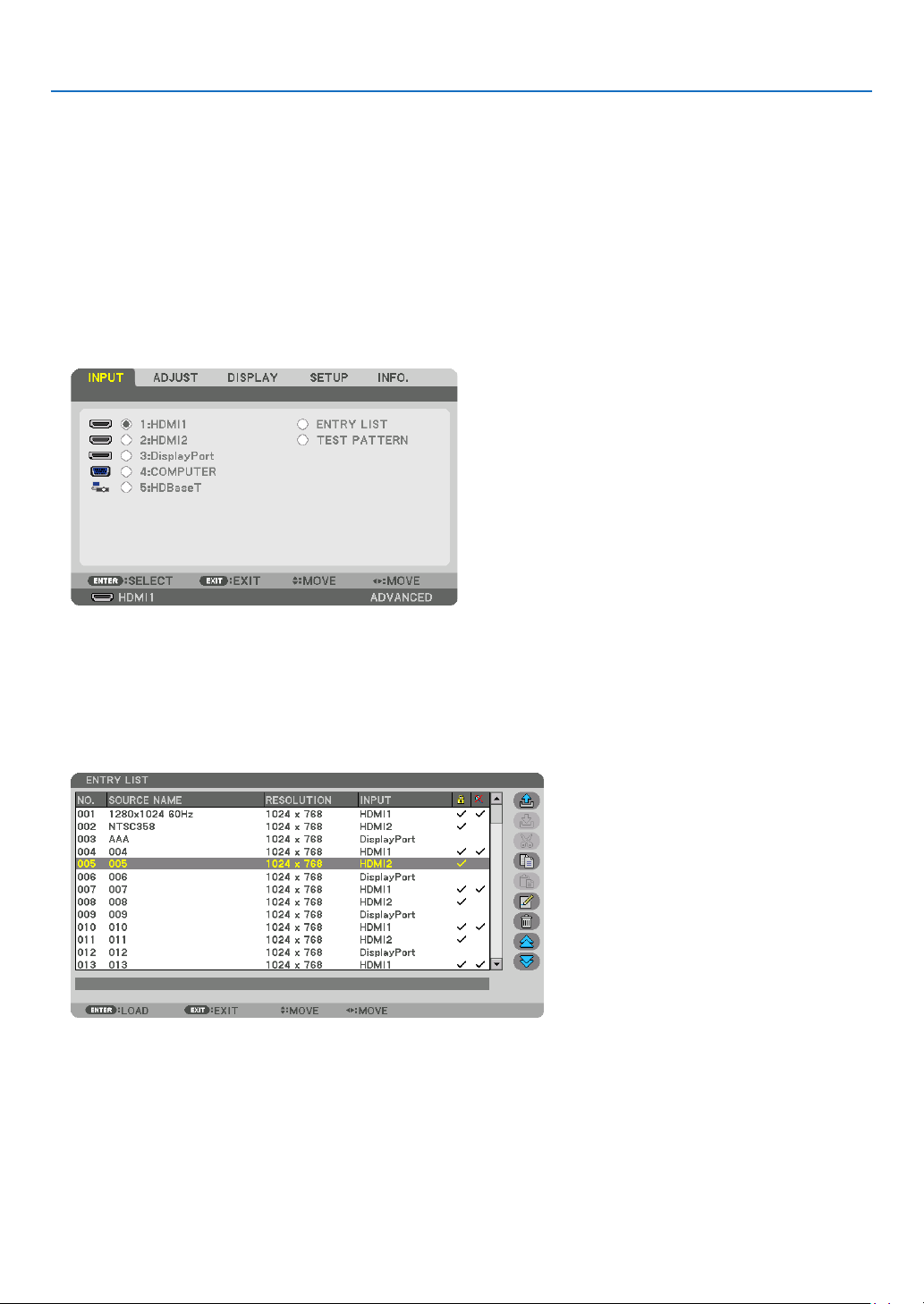
85
5. Using On-Screen Menu
Using the Entry List
Whenanysourceadjustmentsaremade,theadjustmentsareautomaticallyregisteredintheEntryList.The(adjust-
mentvaluesof)registeredsignalscanbeloadedfromtheEntryListwhenevernecessary.
However,onlyupto100patternscanberegisteredintheEntryList.When100patternshavebeenregisteredinthe
EntryList,anerrormessageisthendisplayedandnoadditionalpatternscanberegistered.Youshouldthusdelete
(adjustmentvaluesof)signalsthatarenolongerneeded.
Displaying the Entry list
1. Press the MENU button.
The menu will be displayed.
2. Press the ◀ or ▶buttontoselect[INPUT].
The INPUT list will be displayed.
* This screen belongs to a HDBaseT model.
3. Use the ◀, ▶, ▲, or ▼toselect[ENTRYLIST]andpresstheENTERbutton.
The ENTRY LIST windows will be displayed.
If the ENTRY LIST window is not displayed, switch the menu to [ADVANCED].
To switch the menu between [ADVANCED] and [BASIC], select [SETUP] → [CONTROL] → [TOOLS] → [AD-
MINISTRATOR MODE] → [MENU MODE]. (→ page 113)
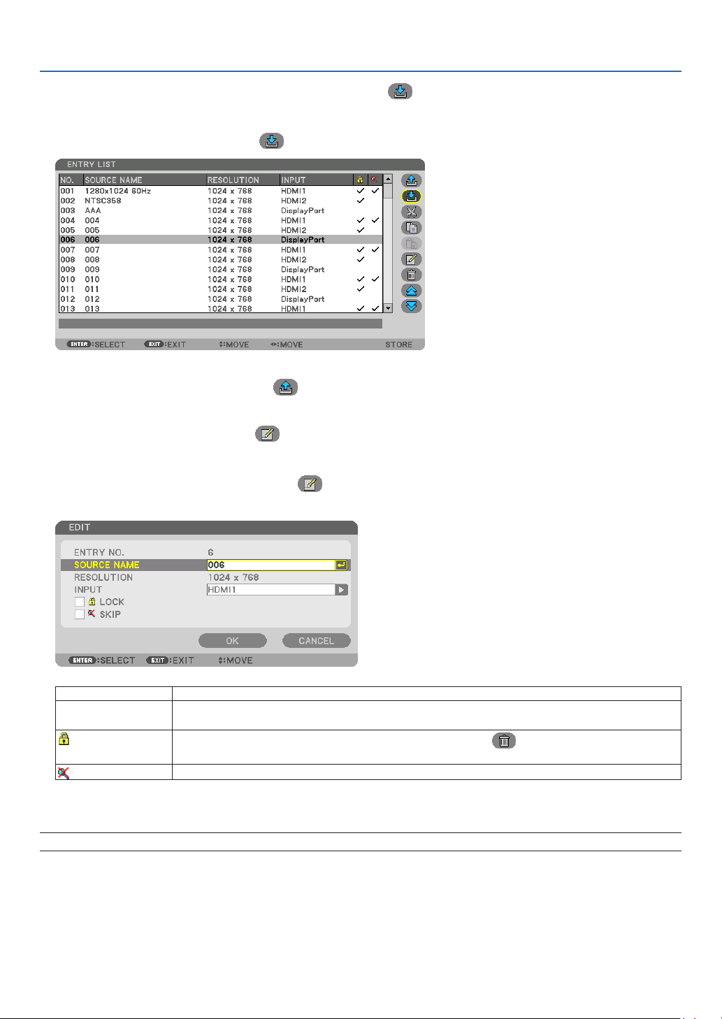
86
5. Using On-Screen Menu
Entering the currently projected signal into the Entry List [ (STORE)]
1. Press the ▲ or ▼ button to select any number.
2. Press the ◀ or ▶buttontoselect[ (STORE)]andpresstheENTERbutton.
Calling up a signal from the Entry List [ (LOAD)]
Press the ▲ or ▼buttontoselectasignalandpresstheENTERbutton.
Editing a signal from the Entry List [ (EDIT)]
1. Press the ▲ or ▼buttontoselectasignalyouwishtoedit.
2. Press the ◀, ▶, ▲, or ▼buttontoselect[ (EDIT)]andpresstheENTERbutton.
The Edit window will be displayed.
SOURCENAME Enterasignalname.Upto18alphanumericcharacterscanbeused.
INPUT The input terminal can be changed. Switching between HDMI/DisplayPort/Computer/
HDBaseTispossible.
LOCK
Setsothattheselectedsignalcannotbedeletedwhen[ (ALLDELETE)]isexecuted.
ThechangesmadeafterLOCKexecutioncannotbesaved.
SKIP
Setsothattheselectedsignalwillbeskippedduringautosearch.
3. Settheaboveitemsandselect[OK]andpresstheENTERbutton.
NOTE: The input terminal cannot be changed to the currently projected signal.
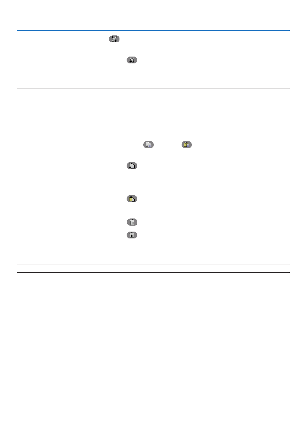
87
5. Using On-Screen Menu
Cutting a signal from the Entry List [ (CUT)]
1. Press the ▲ or ▼buttontoselectasignalyouwishtodelete.
2. Press the ◀, ▶, ▲, or ▼buttontoselect[ (CUT)]andpresstheENTERbutton.
The signal will be deleted from the Entry List and the deleted signal will be displayed on the clipboard at the bot-
tom of the Entry List.
NOTE:
• Thecurrentlyprojectedsignalcannotbedeleted.
• Whenthelockedsignalisselected,itwillbedisplayedingraywhichindicatesitisnotavailable.
TIP:
• DataontheclipboardcanbepassedontotheEntryList.
• DataontheclipboardwillnotbelostaftertheEntryListisclosed.
Copying and pasting a signal from the Entry List [ (COPY)]/[ (PASTE)]
1. Press the ▲ or ▼buttontoselectasignalyouwishtocopy.
2. Press the ◀, ▶, ▲, or ▼buttontoselect[ (COPY)]andpresstheENTERbutton.
The copied signal will be displayed on the clipboard at the bottom of the Entry List.
3. Press the ◀ or ▶ button to move to the list.
4. Press the ▲ or ▼buttontoselectasignal.
5. Press the ◀, ▶, ▲, or ▼buttontoselect[ (PASTE)]andpresstheENTERbutton.
Data on the clipboard will be pasted to the signal.
Deleting all the signals from the Entry List [ (ALLDELTE)]
1. Press the ◀, ▶, ▲, or ▼buttontoselect[ (ALLDELETE)]andpresstheENTERbutton.
The confirmation message will be displayed.
2. Press the ◀ or ▶buttontoselect[YES]andpresstheENTERbutton.
NOTE: The locked signal cannot be deleted.
Using Test Pattern [TEST PATTERN]
Displaysthetestpatternforadjustingdistortiononthescreenandthefocusatthetimeoftheprojectorsetup.Once
the[TESTPATTERN]ontheonscreenmenuisselected,thepatternforadjustmentwillbedisplayedon.Ifyound
distortiononthepattern,adjusttheprojectorinstallationangleorcorrectdistortionbypressingtheGeometric.button
ontheremote.Ifthefocusadjustmentisrequired,presstheFOCUSbuttonontheremotecontrolfordisplayingthe
FOCUSadjustmentscreenandthenadjustFOCUSby◀ or ▶button.Recommendtoperformthefocusadjustment
afterleavingtheprojectorunderthestatetheTESTPATTERNhasbeenprojectedforover30minutes.PressEXIT
button to close the test pattern and return to the menu.
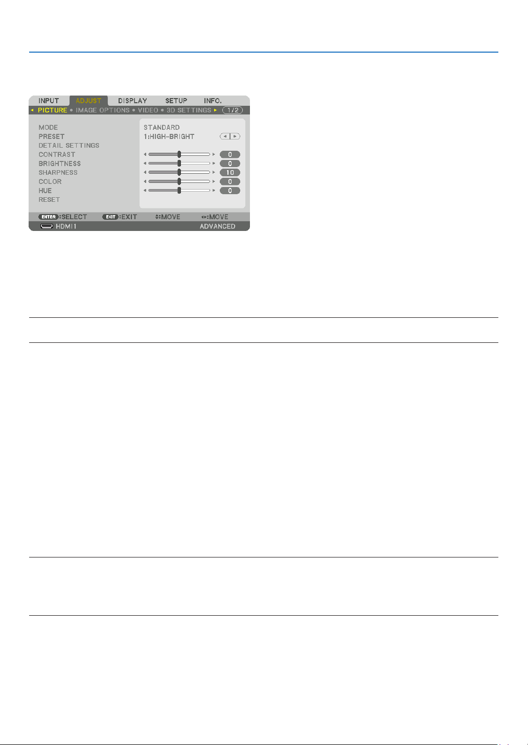
88
5. Using On-Screen Menu
❺ Menu Descriptions & Functions [ADJUST]
[PICTURE]
[MODE]
Thisfunctionallowsyoutodeterminehowtosavesettingsfor[DETAILSETTINGS]of[PRESET]foreachinput.
STANDARD ������������ Saves settings for each item of [PRESET] (Preset 1 through 7)
PROFESSIONAL
����� Saves all the settings of [PICTURE] for each input�
NOTE:
• When[TESTPATTERN]isdisplayed,[MODE]cannotbeselected.
[PRESET]
Thisfunctionallowsyoutoselectoptimizedsettingsforyourprojectedimage.
Youcanadjustneutraltintforyellow,cyanormagenta.
Therearesevenfactorypresetsoptimizedforvarioustypesofimages.Youcanalsouse[DETAILSETTINGS]toset
useradjustablesettingstocustomizeeachgammaorcolor.
Yoursettingscanbestoredin[PRESET1]to[PRESET7].
AUTO ��������������������� Automatically distinguish the optimal setting for the input signal�
HIGH-BRIGHT �������� Recommended for use in a brightly lit room�
PRESENTATION ����� Recommended for making a presentation using a PowerPoint file�
VIDEO �������������������� Recommended for typical TV program viewing�
MOVIE ������������������� Recommended for movies�
GRAPHIC ��������������� Recommended for graphics�
sRGB ��������������������� Standard color values
DICOM SIM� ���������� Recommended for DICOM simulation format�
NOTE:
• The[DICOMSIM.]optionisfortraining/referenceonlyandshouldnotbeusedforactualdiagnosis.
• DICOMstandsforDigitalImagingandCommunicationsinMedicine.ItisastandarddevelopedbytheAmericanCollegeofRadiol-
ogy(ACR)andtheNationalElectricalManufacturersAssociation(NEMA).
The standard specifies how digital image data can be moved from system to system.
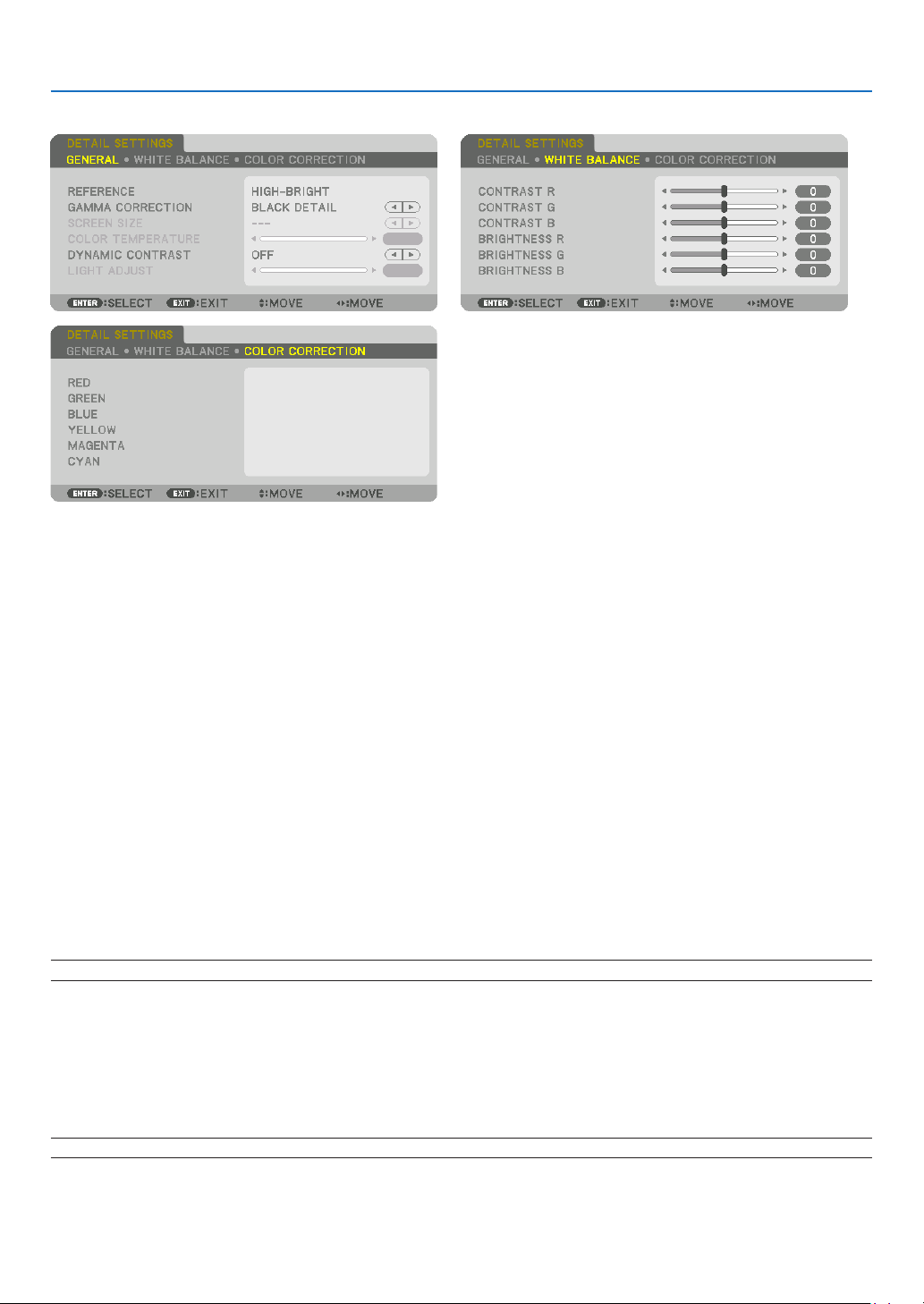
89
5. Using On-Screen Menu
[DETAIL SETTINGS]
[GENERAL]
StoringYourCustomizedSettings[REFERENCE]
Thisfunctionallowsyoutostoreyourcustomizedsettingsin[PRESET1]to[PRESET7].
First,selectabasepresetmodefrom[REFERENCE],thenset[GAMMACORRECTION]and[COLORTEMPERA-
TURE].
HIGH-BRIGHT �������� Recommended for use in a brightly lit room�
PRESENTATION ����� Recommended for making a presentation using a PowerPoint file�
VIDEO �������������������� Recommended for typical TV program viewing�
MOVIE ������������������� Recommended for movies�
GRAPHIC ��������������� Recommended for graphics�
sRGB ��������������������� Standard color values�
DICOM SIM� ���������� Recommended for DICOM simulation format�
Selecting Gamma Correction Mode [GAMMA CORRECTION]
Eachmodeisrecommendedfor:
DYNAMIC �������������� Creates a high-contrast picture�
NATURAL ��������������� Natural reproduction of the picture�
BLACK DETAIL ������� Emphasizes detail in dark areas of the picture�
NOTE:Thisfunctionisnotavailablewhen[DICOMSIM.]isselectedfor[DETAILSETTINGS].
SelectingScreenSizeforDICOMSIM[SCREENSIZE]
Thisfunctionwillperformgammacorrectionappropriateforthescreensize.
LARGE ������������������� For screen size of 150"
MEDIUM
���������������� For screen size of 100"
SMALL
������������������� For screen size of 50"
NOTE:Thisfunctionisavailableonlywhen[DICOMSIM.]isselectedfor[DETAILSETTINGS].

90
5. Using On-Screen Menu
Adjusting Color Temperature [COLOR TEMPERATURE]
Thisoptionallowsyoutoselectthecolortemperatureofyourchoice.
Avaluebetween5000Kand10500Kcanbesetin100Kunits.
NOTE:When[PRESENTATION]or[HIGH-BRIGHT]isselectedin[REFERENCE],thisfunctionisnotavailable.
Adjusting Brightness and Contrast [DYNAMIC CONTRAST]
Whenset,themostoptimalcontrastratioisadjustedaccordingtothevideo.
OFF ������������������������ Dynamic contrast is disabled�
MOTION IMAGE ����� Most optimal settings for moving images�
STILL IMAGE ��������� Most optimal settings for static images� Rapidly follows any changes in the video�
NOTE:
• Dependingontheconditions,projectorsettingssuchas[DYNAMICCONTRAST]maynotbeabletobeselected.
AdjustingBrightness[LIGHTADJUST]
Theadjustmentiseffectivewhen[PROFESSIONAL]isselectedfor[MODE].
Adjusting White Balance [WHITE BALANCE]
Thisallowsyoutoadjustthewhitebalance.Contrastforeachcolor(RGB)toadjustthewhitelevelofthescreen;
Brightnessforeachcolor(RGB)isusedtoadjusttheblacklevelofthescreen.
[COLOR CORRECTION]
Correctsthecolorforallsignals.
Adjuststhetoneforthecolorsred,green,blue,yellow,magentaandcyan.
RED HUE +Direction Magentadirection
−Direction Yellowdirection
SATURATION +Direction Vivid
−Direction Weak
GREEN HUE
+Direction Yellowdirection
−Direction Cyandirection
SATURATION +Direction Vivid
−Direction Weak
BLUE HUE
+Direction Cyandirection
−Direction Magentadirection
SATURATION +Direction Vivid
−Direction Weak
YELLOW HUE
+Direction Reddirection
−Direction Greendirection
SATURATION +Direction Vivid
−Direction Weak
MAGENTA HUE
+Direction Bluedirection
−Direction Reddirection
SATURATION +Direction Vivid
−Direction Weak
CYAN HUE
+Direction Greendirection
−Direction Bluedirection
SATURATION +Direction Vivid
−Direction Weak
[CONTRAST]
Adjuststheintensityoftheimageaccordingtotheincomingsignal.
[BRIGHTNESS]
Adjuststhebrightnesslevelorthebackrasterintensity.

91
5. Using On-Screen Menu
[SHARPNESS]
Controlsthedetailoftheimage.
[COLOR]
Increasesordecreasesthecolorsaturationlevel.
[HUE]
Variesthecolorlevelfrom+/−greento+/−blue.Theredlevelisusedasreference.
NOTE:
• When[TESTPATTERN]isdisplayed,[CONTRAST],[BRIGHTNESS],[SHARPNESS],[COLOR]and[HUE]cannotbeadjusted.
[RESET]
Thesettingsandadjustmentsfor[PICTURE]willbereturnedtothefactorydefaultsettingswiththeexceptionofthe
following;Presetnumbersand[REFERENCE]withinthe[PRESET]screen.
Thesettingsandadjustmentsunder[DETAILSETTINGS]withinthe[PRESET]screenthatarenotcurrentlyselected
will not be reset.
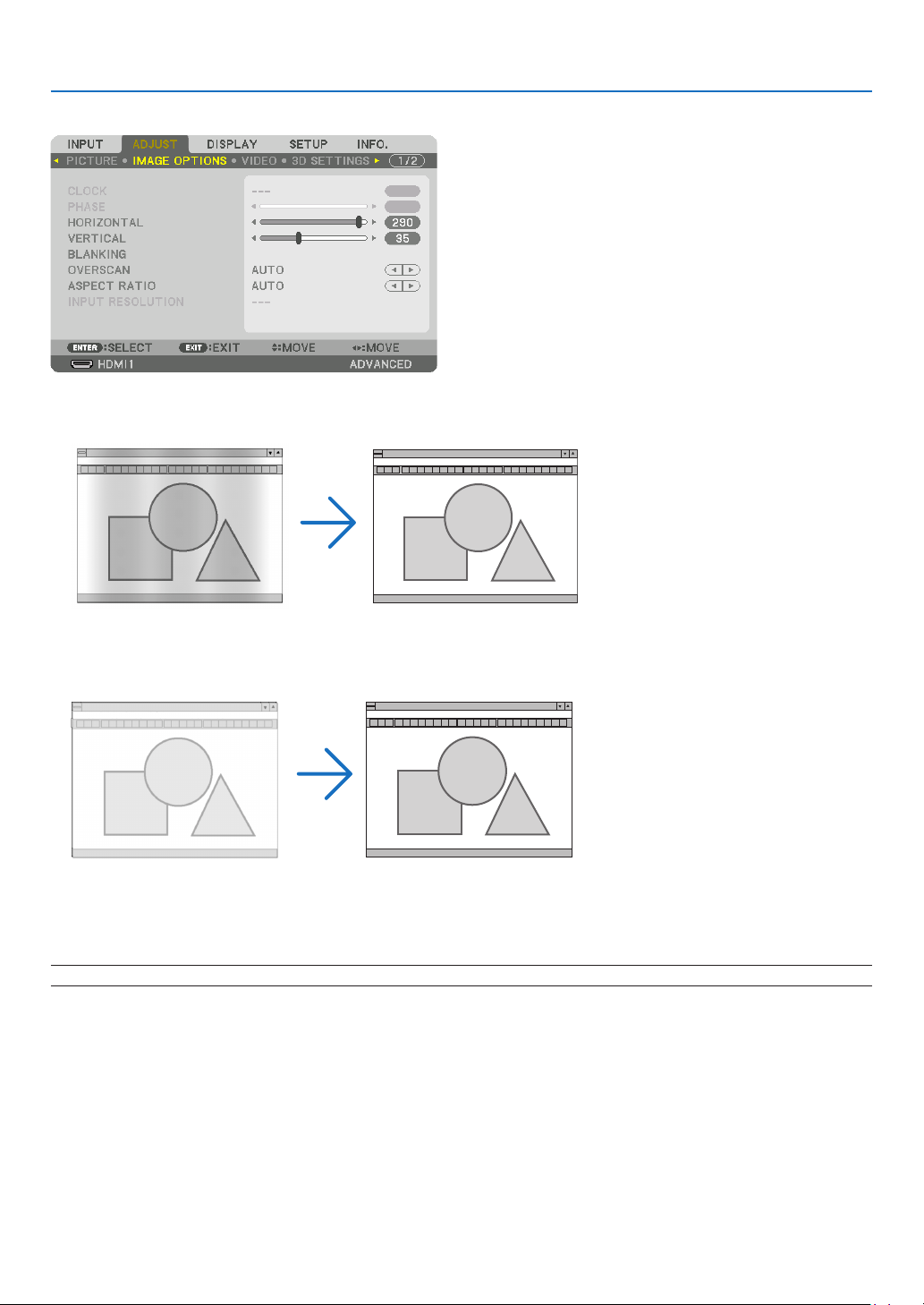
92
5. Using On-Screen Menu
[IMAGE OPTIONS]
Adjusting Clock and Phase [CLOCK/PHASE]
ThisallowsyoutomanuallyadjustCLOCKandPHASE.
CLOCK ������������������� Use this item to fine tune the computer image or to remove any vertical banding that might appear� This
function adjusts the clock frequencies that eliminate the horizontal banding in the image�
This adjustment may be necessary when you connect your computer for the first time�
PHASE ������������������� Use this item to adjust the clock phase or to reduce video noise, dot interference or cross talk� (This is
evident when part of your image appears to be shimmering�)
Use [PHASE] only after the [CLOCK] is complete�
NOTE:The[CLOCK]and[PHASE]itemsareavailableforRGBsignalsonly.
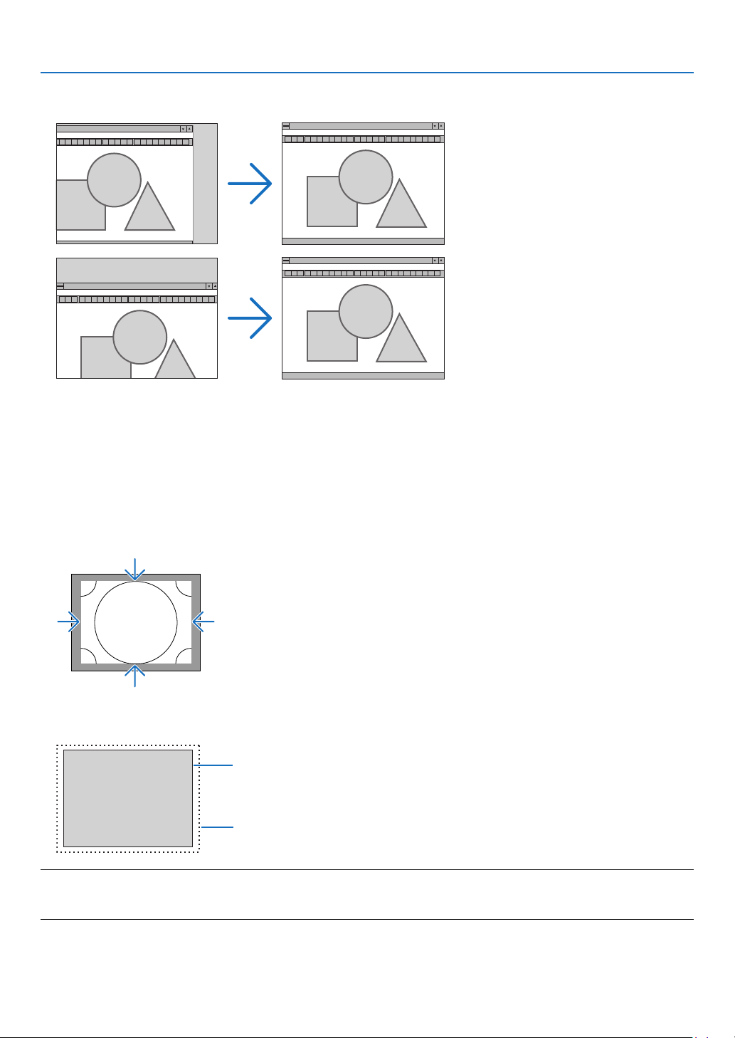
93
5. Using On-Screen Menu
AdjustingHorizontal/VerticalPosition[HORIZONTAL/VERTICAL]
Adjuststheimagelocationhorizontallyandvertically.
• Animagecanbedistortedduringtheadjustmentof[CLOCK]and[PHASE].Thisisnotmalfunction.
• Theadjustmentsfor[CLOCK],[PHASE],[HORIZONTAL],and[VERTICAL]willbestoredinmemoryforthecur-
rentsignal.Thenexttimeyouprojectthesignalwiththesameresolution,horizontalandverticalfrequency,its
adjustments will be called up and applied.
Todeleteadjustmentsstoredinmemory,fromthemenu,youselect[SETUP]→[RESET]→[CURRENTSIGNAL]
and reset the adjustments.
[BLANKING]
Adjuststhedisplayrange(blanking)atthetop,bottom,leftandrightedgesoftheinputsignal.
SelectingOverscanPercentage[OVERSCAN]
Selectoverscanpercentage(Auto,0%,5%and10%)forsignal.
Projected image
Overscaned by 10%
NOTE:
• The[OVERSCAN]itemisnotavailable:
-when[NATIVE]isselectedfor[ASPECTRATIO].
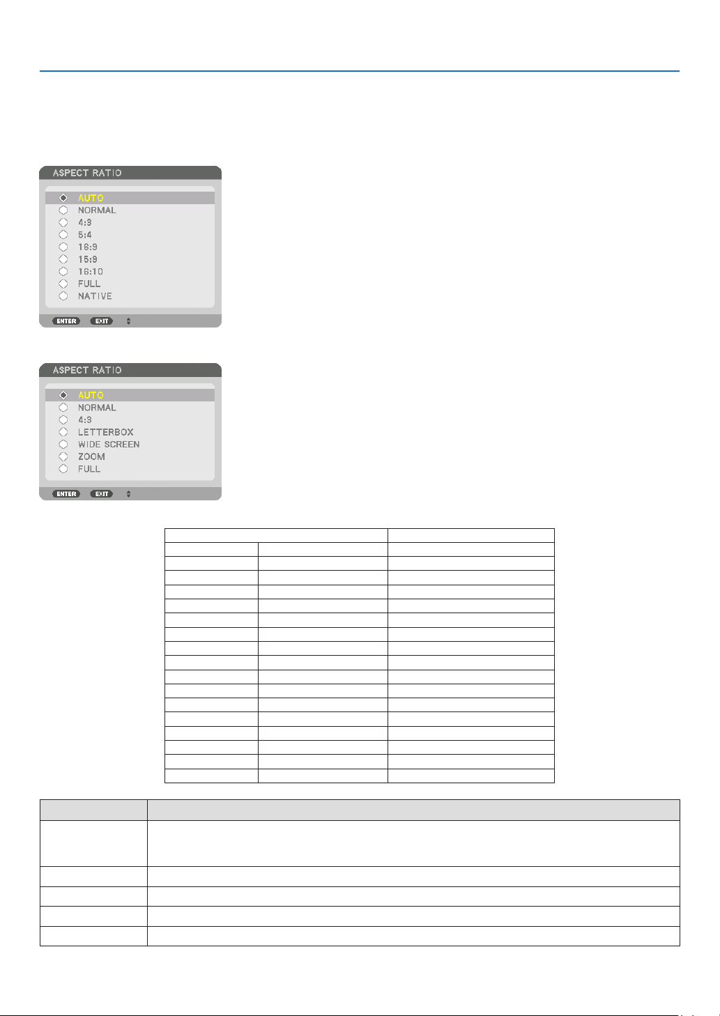
94
5. Using On-Screen Menu
Selecting the Aspect Ratio [ASPECT RATIO]
Usethisfunctiontoselectthescreen’slateral:longitudinalaspectratio.
Theprojectorautomaticallyidentiesthesignalbeinginputandsetstheoptimumaspectratio.
For Computer signal
ForHDTV/SDTVsignals
Resolution AspectRatio
VGA 640×480 4:3
SVGA
800×600 4:3
XGA
1024×768 4:3
WXGA
1280×768 15:9
WXGA
1280×800 16:10
HD(FWXGA)
1366×768 approx.16:9
WXGA+ 1440×900 16:10
SXGA
1280×1024 5:4
SXGA+
1400×1050 4:3
WXGA++
1600×900 16:9
UXGA
1600×1200 4:3
WSXGA+
1680×1050 16:10
FHD(1080P)
1920×1080 16:9
WUXGA
1920×1200 16:10
WQXGA
2560×1600 16:10
QuadHD 3840×2160 16:9
QuadHD 4096×2160 19:7
Options Function
AUTO
Theprojectorwillautomaticallydeterminetheincomingsignalanddisplayitinitsaspectratio.
Theprojectormayerroneouslydeterminetheaspectratiodependingonitssignal.Ifthisoccurs,select
theappropriateaspectratiofromthefollowing.
NORMAL Theimageisdisplayedinitsoriginalaspectratioofitsinputsignal..
4:3 Theimageisdisplayedin4:3aspectratio.
5:4 Theimageisdisplayedin5:4aspectratio
16:9 Theimageisdisplayedin16:9aspectratio
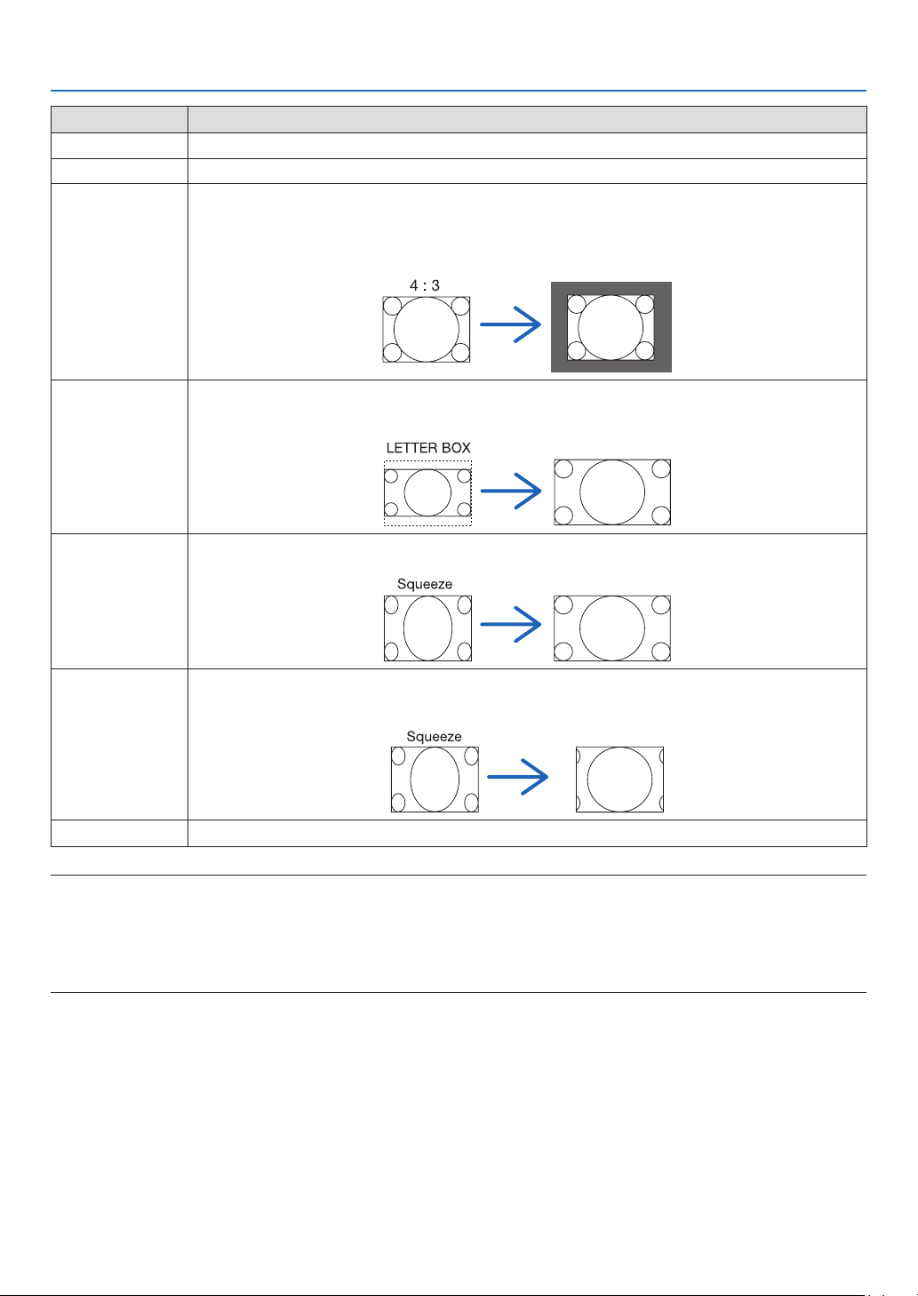
95
5. Using On-Screen Menu
Options Function
15:9
Theimageisdisplayedin15:9aspectratio
16:10 Theimageisdisplayedin16:10aspectratio
NATIVE Theprojectordisplaysthecurrentimageinitstrueresolutionwhentheincomingcomputersignalhasa
lowerorhigherresolutionthantheprojector’snativeresolution.(→page2)
Whentheincomingcomputersignalhasahigherresolutionthantheprojector'snativeresolution,the
centerofanimagewillbedisplayed.
LETTERBOX Theimageofaletterboxsignal(16:9)isstretchedequallyinthehorizontalandverticaldirectionstotthe
screen.
WIDESCREEN Theimageofasqueezesignal(16:9)isstretchedleftandrightin16:9.
ZOOM Theimageofasqueezesignal(16:9)isstretchedleftandrightin4:3.
Partsofthedisplayedimagearecroppedattheleftandrightedgesandthereforenotvisible.
FULL Projecttofullscreensize.
TIP:
• Imagepositioncanbeadjustedverticallyusing[POSITION]whenthe[16:9],[15:9],or[16:10]aspectratiosareselected.
• Theterm“letterbox”referstoamorelandscape-orientedimagewhencomparedtoa4:3image,whichisthestandardaspect
ratio for a vide source.
Theletterboxsignalhasaspectratioswiththevistasize“1.85:1”orcinemascopesize“2.35:1”formovielm.
• Theterm“squeeze”referstothecompressedimageofwhichaspectratioisconvertedfrom16:9to4:3.
[INPUT RESOLUTION]
Theresolutionisassignedautomaticallywhentheresolutionoftheinputsignalfromthecomputervideoinputterminal
(analogRGB)cannotbedistinguished.

96
5. Using On-Screen Menu
[VIDEO]
Using Noise Reduction [NOISE REDUCTION]
Whenprojectingavideoimage,youcanusethe[NOISEREDUCTION]functiontoreducethescreennoise(roughness
anddistortion).Thisdeviceisequippedwiththreetypesofnoisereductionfunctions.Selectthefunctionaccordingto
thetypeofnoise.Dependingonthenoiselevel,thenoisereductioneffectcanbesetto[OFF],[LOW],[MEDIUM]or
[HIGH].[NOISEREDUCTION]canbeselectedforSDTV,HDTVsignalandcomponentsignalinput.
RANDOM NR ��������� Reduces flickering random noise in an image�
MOSQUITO NR ������ Reduces mosquito noise that appears around the edges of an image during Blu-ray playback�
BLOCK NR ������������� Reduces block noise or mosaic-like patterns�
Selecting Interlaced Progressive Conversion Process Mode [DEINTERLACE]
Thisfunctionallowsyoutoselectaninterlaced-to-progressiveconversionprocessforvideosignals.
NORMAL ���������������� Automatically distinguishes a moving image from a static image to create a distinct image� Please select
[MOVIE] if there are any obvious jitter and noises�
MOVIE ������������������� Select when projecting moving images� This is suitable for signals with a lot of jitter and noise�
STILL ��������������������� Select when projecting static images� The video will flicker when a moving image is projected�
[CONTRAST ENHANCEMENT]
Usingthecharacteristicsofthehumaneye,apicturequalitywithasenseofcontrastandresolutionisachieved.
OFF ������������������������ Suite vision is switched off�
AUTO ��������������������� Contrast and picture quality are automatically improved using the suite vision function�
NORMAL ���������������� Adjust the gain manually�

97
5. Using On-Screen Menu
[SIGNAL TYPE]
SelectionofRGBandcomponentsignals.Normally,thisissetto[AUTO].Pleasechangethesettingifthecolorof
theimageremainsunnatural.
AUTO ��������������������� Automatically distinguishes RGB and component signals�
RGB ����������������������� Switches to the RGB input�
REC601 ������������������ Switches to the component signal conforming to the ITU-R Rec601 standard�
Setting appropriate to SDTV images�
REC709 ������������������ Switches to the component signal conforming to the ITU-R Rec709 standard�
Setting appropriate to Hi-Vision images�
REC2020 ���������������� Switches to the component signal conforming to the ITU-R Rec2020 standard�
Setting appropriate to 4K images�
[VIDEOLEVEL]
SelectionofthevideosignallevelwhenconnectinganexternaldevicetotheHDMI1INterminal,HDMI2INterminal,
DisplayPortinputterminal,andHDBaseTinputterminaloftheprojector.
AUTO ��������������������� The video level is switched automatically based on the information from the device outputting the signal�
Depending on the connected device, this setting may not be made properly� In this case, switch to [NORMAL”
or “ENHANCED” from the menu and view with the optimum setting�
NORMAL ���������������� This disables the enhanced mode�
ENHANCED ������������ This improves the image’s contrast, expressing the dark and light sections more dynamically�
SUPER WHITE ������� The video contrast is improved and the dark areas appear more dynamic�
[HDR MODE]
AUTO ��������������������� Automatically distinguishes HDR signal�
OFF ������������������������ Projects the image based on the input signal
ON
������������������������� Projects the image conforming to the HDR signal
Note:Theseoptionsareavailableexclusivelyfor4Ksignal.

98
5. Using On-Screen Menu
[3D SETTINGS]
Pleasereferto“3-9Projecting3Dvideos”(→page46)fortheoperation.
STEREOVIEWER
Stackupasingleormultipleprojectorsandcarryoutthesettingsforprojecting3Dvideos.Selecttheleft/rightset-
tingsofthe3Deyewearusingthestereoviewer.
SINGLE ������������������ Use a single projector to project 3D videos�
DUAL LEFT ������������ Use a dedicated projector for displaying videos on the left�
DUAL RIGHT ���������� Use a dedicated projector for displaying videos on the right�
STEREO FILTER
Stackupasingle ormultipleprojectorsand carry outthesettingsfor projecting 3Dvideos.Imagesetting for 3D
glassesmadebyIntec.
SINGLE ������������������ Use a single projector to project 3D videos�
DUAL LEFT ������������ Use a dedicated projector for displaying videos on the left�
DUAL RIGHT ���������� Use a dedicated projector for displaying videos on the right�
FORMAT
Selectthe3Dvideoformat(recording/transmissionformat).Selecttomatchthe3Dbroadcastand3Dmedia.Nor-
mally,[AUTO]isselected.Pleaseselectthe3Dinputsignalformatwhenthe3Ddetectionsignaloftheformatcannot
bedistinguished.
L/RINVERT
Invertthedisplayorderoftheleftandrightvideos.
Select[ON]ifyoufeeluncomfortablewiththe3Ddisplaywhen[OFF]isselected.
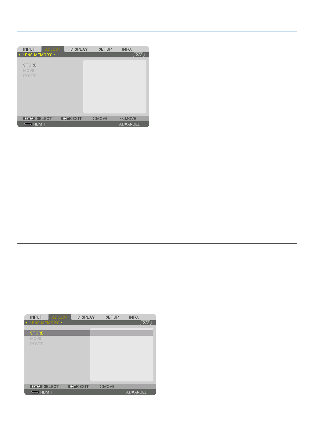
99
5. Using On-Screen Menu
Using the Lens Memory Function [LENS MEMORY]
ThisfunctionservestostoretheadjustedvaluesforeachinputsignalwhenusingtheLENSSHIFT,ZOOMandFO-
CUSbuttonsoftheprojector.Adjustedvaluescanbeappliedtothesignalyouselected.Thiswilleliminatetheneed
toadjustlensshift,focus,andzoomatthetimeofsourceselection.
STORE ������������������� Stores the current adjusted values in memory for each input signal�
MOVE �������������������� Applies the adjusted values to the current signal�
RESET �������������������� Returns the adjusted values to the last condition�
• ThelensunitsNP11FL,NP12ZL,NP13ZL,NP14ZL,andNP30ZLdonotsupportthisfunction.
NOTE:
• LensmemoryadjustmentswillbeautomaticallyregisteredtheENTRYLIST.Theselensmemoryadjustmentscanbeloadedfrom
theENTRYLIST.(→ page 85)
Notethatperforming[CUT]or[ALLDELETE]intheENTRYLISTwilldeletelensmemoryadjustmentsaswellassourceadjust-
ments. This deletion will not take effect until other adjustments is loaded.
• Forstoringeachadjustmentoflensshift,motorizedzoomandmotorizedfocusascommonvalueforallinputsignal,storethem
as reference lens memory.
Tostoreyouradjustedvaluesin[LENSMEMORY]:
1. Projecttheconnecteddevicesignalyouwanttoadjust.
2. Adjusttheprojectingimageofposition,sizeandfocusbytheLENSSHIFT/HOMEPOSITION,ZOOM+/−,and
FOCUS+/−buttons.
• Adjustmentcanbeperformedbytheremotecontrol.Pleasereferto“AdjustingthePictureSizeandPosition”
on page 21.
• Slightadjustmentbymovingtheprojectorpositionandbythetiltfootisnotsubjectof[LENSMEMORY].
3.Movethecursoron[STORE]andpressENTER.
4.Movethecursoron[YES]andpressENTER.
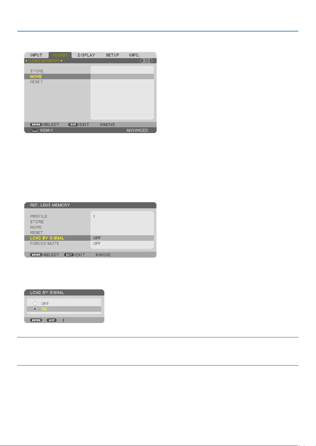
100
5. Using On-Screen Menu
Tocalluptheadjustedvaluesfrom[LENSMEMORY]:
1. Fromthemenu,select[ADJUST]→[LENSMEMORY]→[MOVE]andpresstheENTERbutton.
The confirmation screen will be displayed.
2. Press the ◀buttontoselectand[YES]andpresstheENTERbutton.
During projection, if the adjusted values for an input signal have been saved, the lens will shift. If not, the lens will
shift according to the adjusted values stored in the selected [REF. LENS MEMORY] [PROFILE] number.
Toautomaticallyapplytheadjustedvaluesatthetimeofsourceselection:
1. Fromthemenu,select[SETUP]→[INSTALLATION]→[REF.LENSMEMORY]→[LOADBYSIGNAL]and
presstheENTERbutton.
2. Press the ▼buttontoselectand[ON]andpresstheENTERbutton.
This will move the lens automatically to the position at the time of source selection according to the adjusted
values.
NOTE:
• TheLensMemoryfunctionmaynotproduceacompletelyalignedimage(duetotolerancesinthelenses)usingtheadjusted
valuesstoredintheprojector.AftercallingupandapplyingtheadjustedvaluesfromtheLensMemoryfunction,nelyadjustthe
lens shift, zoom and focus to produce the best possible image.

101
5. Using On-Screen Menu
❻ Menu Descriptions & Functions [DISPLAY]
[PIP/PICTURE BY PICTURE]
SUB INPUT
Selecttheinputsignaltobedisplayedinthesub-display.
Pleasereferto“4-2DisplayingTwoPicturesattheSameTime”(→page66)fordetailsontheoperation.
MODE
SelecteitherPIP(PICTUREINPICTURE)orPICTUREBYPICTUREwhenswitchingto2-screendisplay.
PICTURE SWAP
Thevideosinthemaindisplayandsub-displaywillbeswitched.
Pleasereferto“4-2DisplayingTwoPicturesattheSameTime”(→page68)fordetails.
PIP SETTING
Selectthedisplayposition,positionadjustmentandsizeofthesub-displayinthePIPscreen.
START POSITION ��� Selection of the display position of the sub-display when switching to the PIP screen�
HORIZONTAL POSITION
������������������������������ Adjust the display position of the sub-display in the horizontal direction� The respective corners will serve
as reference points�
VERTICAL POSITION
������������������������������ Adjust the display position of the sub-display in the vertical direction� The respective corners will serve as
reference points�
SIZE ����������������������� Select the display size of the sub-display�
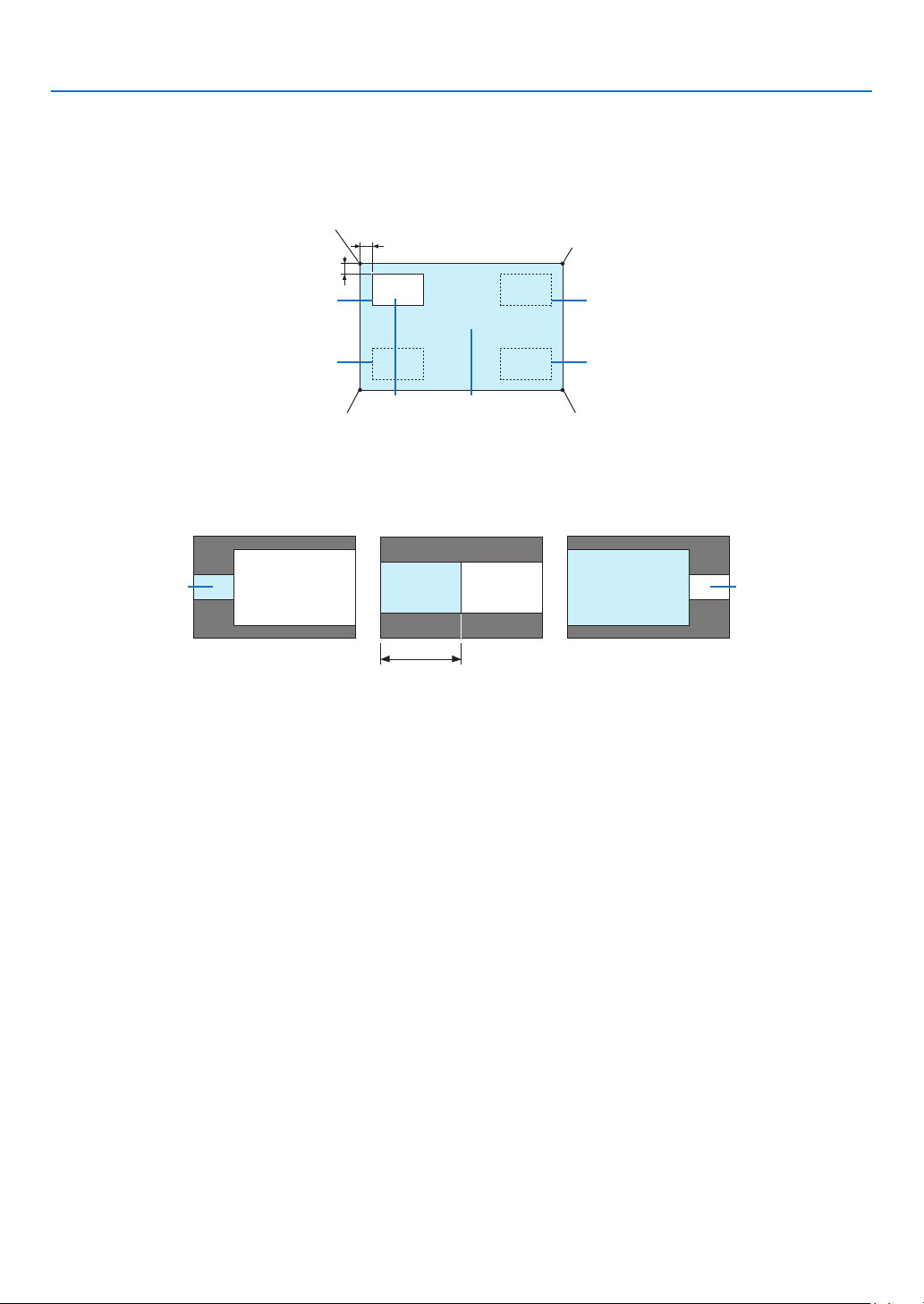
102
5. Using On-Screen Menu
TIP:
Thehorizontalpositionandverticalpositionaretheamountofmovementfromthereferencepoints.Forexample,whenTOP-LEFT
is adjusted, the position is displayed with the same amount of movement even if displayed with other starting positions.
The maximum amount of movement is half the resolution of the projector.
Reference point
Adjust using the horizon-
tal position
Sub-display Main display
Reference point
Adjust using the vertical position
TOP-LEFT TOP-RIGHT
BOTTOM-LEFT BOTTOM-RIGHT
Reference pointReference point
BORDER
Selectthedisplayboundaryofthemaindisplayandsub-displayofthe[PICTUREBYPICTURE]screen.
Display boundary
Main display
Sub-displayMain display
Sub-display
Main displaySub-display
TIP:
• ForWUXGAtype,sevenoptionsfromzerotosixareavailable.
• ForWXGAtype/XGAtype,threeoptionsfromzerototwoareavailable.
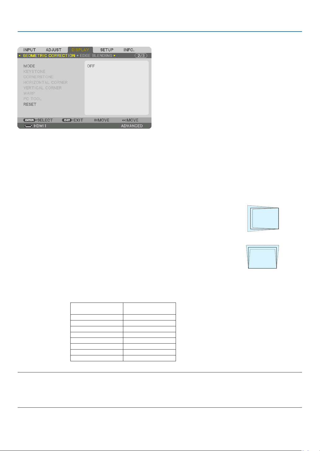
103
5. Using On-Screen Menu
[GEOMETRIC CORRECTION]
MODE
Setpatternforcorrectingdistortion.If[OFF]isselected,the[GEOMETRICCORRECTION]becomesineffective.
Ifyouneedtochangeeitherthe[MENUANGLE]or[MENUPOSITION],makesuretochangethesebeforeperforming
the[GEOMETRICCORRECTION].Ifeitherofthemischangedafterperformingthe[GEOMETRICCORRECTION],
corrected values will be reset to the default values.
KEYSTONE
Correctdistortioninhorizontalandverticaldirections.
HORIZONTAL ��������� Adjustments when projecting from a diagonal direction to the
screen�
VERTICAL �������������� Adjustments when projecting from the top or bottom direction to
the screen�
TILT ����������������������� Adjusts the distortion when performing trapezoidal correction with the screen moved in the vertical direction
using the lens shift�
THROW RATIO ������� Adjusts according to the projection ratio of the optional lens used�
Model name of lens
unit
Adjustmentrange
NP11FL 8
NP30ZL 8–10
NP12ZL 12–15
NP13ZL 15–30
NP14ZL 29–47
NP40ZL 8-11
NP41ZL 13-30
NP43ZL 30-60
NOTE:
• Whenpowerissuppliedtothedevice,theadjustmentvalueofthe[KEYSTONE]usedpreviouslyisretainedevenifthegradient
of the device is changed.
• Aselectricalcorrectioniscarried out by[KEYSTONE],thebrightnessmaybe reduced orthescreenqualitymaydeteriorate
sometimes.
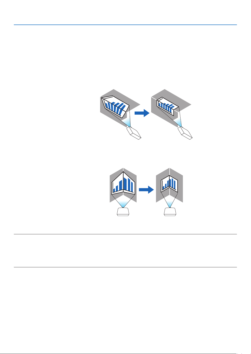
104
5. Using On-Screen Menu
CORNERSTONE
Displaythe4-pointcorrectionscreenandadjustthetrapezoidaldistortionoftheprojectionscreen.
Pleasereferto“CorrectingHorizontalandVerticalKeystoneDistortion[CORNERSTONE]”(→page38)fordetails
on the operation.
HORIZONTALCORNER/VERTICALCORNER
Distortioncorrectionforcornerprojectionsuchaswallsurfaces.
HORIZONTAL CORNER
������������������������������ Performs correction for projection onto a wall lying at an angle to the horizontal direction�
* Reverse angle correction is also possible�
VERTICAL CORNER
������������������������������ Performs correction for projection onto a wall lying at an angle to the vertical direction�
* Reverse angle correction is also possible�
NOTE:
• Whenthemaximumadjustmentrangeisexceeded,distortionadjustmentisdisabled.Setuptheprojectoratanoptimalangleas
the deterioration in the image quality increases as the distortion adjustment volume gets larger.
• Pleasenotethattheimagewillgooutoffocusduetothedifferenceinthedistancebetweentheupperandlowerorleftandright
sidesandthecenterofthescreenforprojectionscuttingacrosscorners.Lenseswithshortfocalpointsarealsonotrecommended
for projections cutting across corners as the image will go out of focus.
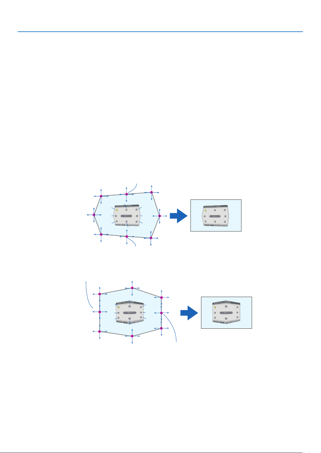
105
5. Using On-Screen Menu
Adjustment method
1. Alignthecursorwiththe[HORIZONTALCORNER]or[VERTICALCORNER]ofthe[GEOMETRICCORREC-
TION]menuandthenpresstheENTERbutton.
• Theadjustmentscreenwillbedisplayed.
2. Press the ▼▲◀▶buttonstoalignthecursor(yellowbox)withthetargetadjustmentpointandthenpress
theENTERbutton.
• Thecursorwillchangeintoanadjustmentpoint(yellowincolor).
3. Press the ▼▲◀▶buttonstoadjustthecornersorsidesofthescreenandthenpresstheENTERbutton.
• Theadjustmentpointwillgobacktobeingacursor(yellowbox).
Explanation of screen transition
• Theadjustmentpointsofthefourcorners(a,c,fandhinthedrawing)willmoveindependently.
• Thefollowingadjustmentpointsdifferatthe[HORIZONTALCORNER]and[VERTICALCORNER].
HORIZONTAL CORNER: When Point b in the drawing is moved, and the upper side and Point g are moved,
the lower side will move in a parallel manner.
VERTICAL CORNER: When Point d in the drawing is moved, and the left side and Point e are moved, the right
side will move in a parallel manner.
[Adjustment points of the [HORIZONTAL CORNER] screen and movement points of the projection screen]
a
b
b
c
d
e
f
g
h
a
c
d
e
f
g
h
Point b will be displaced in a parallel manner at the same time as Points a, b, c
Point g will be displaced in a parallel manner at the same time as Points f, g, h
[Adjustment points of the [VERTICAL CORNER] screen and movement points of the projection screen]
a
a
b
b
c
c
d
d
e
e
f
f
g
g
h
h
Point d will be displaced in a parallel manner at the same time as Points a, d, f
Point e will be displaced in a parallel manner at the same time as Points f, g, h
4. Start from Step 2 onwards to adjust the other points.
5. Whentheadjustmentiscompleted,pressthe▼▲◀▶buttonstoalignthecursorwiththe[EXIT]inthead-
justmentscreenandthenpresstheENTERbutton.
• Switchtothe[GEOMETRICCORRECTION]menuscreen.
TIP:
AcommerciallyavailableUSBmouseisavailabletoperformcorrection.(→ page 40)
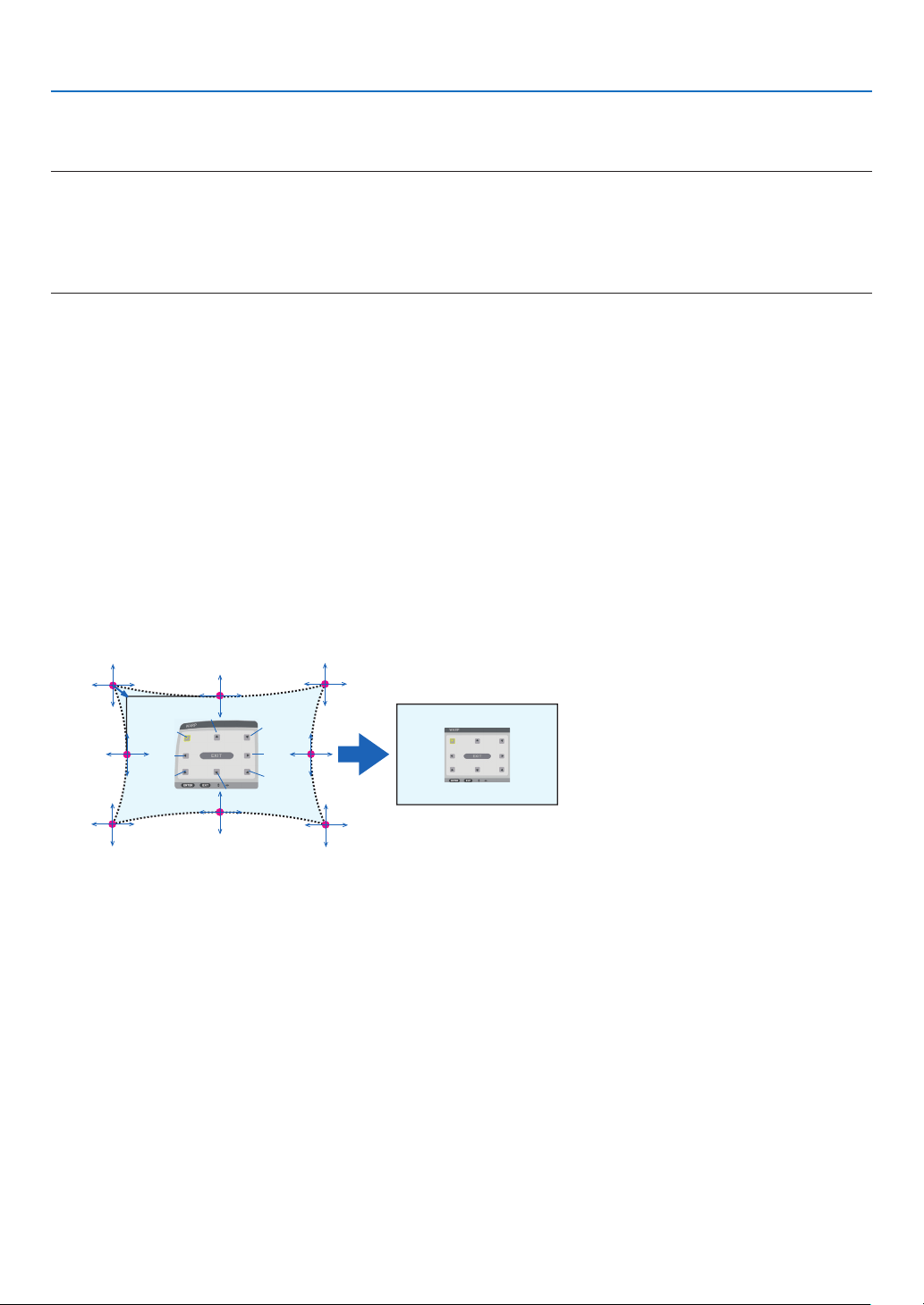
106
5. Using On-Screen Menu
WARP
Correctprojectedimagedistortiononaspecicsurfaceasacolumnorasphere.
NOTE:
• Whenthemaximumadjustmentrangeisexceeded,distortionadjustmentisdisabled.Setuptheprojectoratanoptimalangle
since the more the adjustment volume gets large, the more image quality gets deterioration.
• Pleasenotethattheimagewillgooutoffocusduetothedifferenceinthedistancebetweenperipheriesandthecenterofthescreen
forprojectionscuttingacrosscornersasonacolumnorasphere.Lenseswithshortfocalpointsarealsonotrecommendedfor
projections cutting across corners as the image will go out of focus.
Adjustment method
1. Alignthecursorwiththe[WARP]ofthe[GEOMETRICCORRECTION]menuandthepresstheENTER.
• Adjustmentscreenwillbedisplayedon.
2. Press the ▼▲◀▶buttonstoalignthecursor(bluebox)withthetargetadjustmentpointandthenpressthe
ENTER.
• Thecursorwillchangeintoanadjustmentpoint(yellowincolor).
3. Press the ▼▲◀▶buttonstoadjustthecornersorsidesofthescreenandthenpresstheENTER.
• Thecursorwillbacktoyellowbox.
Explanation for correcting distortion
• Eightadjustmentpointscanbemovedindependently.
• Forleftandrightsides,use◀/▶ buttons for adjusting the range of distortion, and ▼/▲ buttons for adjusting
the distortion peak.
• Fortopandbottomsides,use▼/▲ buttons for adjusting the range of distortion, and ◀/▶ buttons for adjusting
the distortion peak.
• Forcorners,use▼▲◀▶ buttons for moving positions.
a
b
c
e
h
d
g
f
b
a
c
d
e
f
g
h
4. Foradjustingotherpoints,repeatStep2onwards.
5. Whentheadjustmentiscompleted,movethecursorontothe[EXIT]ontheadjustmentscreenandpress
theENTER.
• Thescreenwillbeswitchedtothe[GEOMETRICCORRECTION]menu.
The adjustment completion screen will be displayed on.
6. Press◀ or ▶buttontomovethecursoronto[OK]thenpress[ENTER].
• TheadjustedvaluesforWARParestoredandthescreendisplaygoesbacktothe[GEOMETRICCORREC-
TION].
TIP:
AcommerciallyavailableUSBmouseisavailabletoperformcorrection.(→ page 40)

107
5. Using On-Screen Menu
PC TOOL
Recallthegeometriccorrectiondatathatisregisteredintheprojectorbeforehand.
Threetypesofcorrectiondatacanberegistered.
NOTE:
• Aselectricalcorrectioniscarriedoutingeometriccorrection,thebrightnessmaybeaffectedandthepicturequalitymaybe
degraded.
RESET
ResettheadjustmentvaluethathasbeensetupasMODEinGEOMETRICCORRECTION(returntotheinitialvalue).
• ThisisineffectivewhenMODEissetOFF.
• ResetcanbeexecutedbypressingandholdingtheGeometericbuttonontheremotecontrolforover2seconds.

108
5. Using On-Screen Menu
[EDGE BLENDING]
Thisadjuststheedges(boundaries)oftheprojectionscreenwhenprojectinghighresolutionvideosusingacombina-
tionofseveralprojectorsintheup,down,leftandrightpositions.
MODE
ThisenablesordisablestheEDGEBLENDINGfunction.
WhenMODEissettoON,theTOP,BOTTOM,LEFT,RIGHT,BLACKLEVELandBLENDCURVEsettingscanbe
adjusted.
TOP/BOTTOM/LEFT/RIGHT
ThisselectstheEDGEBLENDINGlocationsontheleft,right,topandbottomonthescreen.
Thefollowingsettingscanbeadjustedwhenanitemisselected.(→page70)
CONTROL �������������� Enable TOP, BOTTOM, LEFT and RIGHT functions�
MARKER ���������������� Set whether to display marker or not when adjusting the range and display position� When turned on, a
magenta marker for adjusting the range adjustment and a green marker for adjusting the display position
will be displayed�
RANGE ������������������� Adjust the range (width) of the edge blending�
POSITION �������������� Adjust the display position of the edge blending�
BLACKLEVEL
Dividethescreenintoninepartsandkeeptheblackleveluniformforeachprojector.
TheninedivisionsscreensareTOP-LEFT,TOP-CENTER,TOP-RIGHT,CENTER-LEFT,CENTER,CENTER-RIGHT,
BOTTOM-LEFT,BOTTOM-CENTERandBOTTOM-RIGHT.(→page74)
BLENDCURVE
SetbrightnessfortheEDGEBLENDINGsections.(→page73)

109
5. Using On-Screen Menu
[MULTI SCREEN]
WHITE BALANCE
Thisadjuststhewhitebalanceforeachprojectorwhenprojectingusingacombinationofseveralprojectors.
Thiscanbeadjustedwhen[MODE]issetto[ON].
CONTRAST W, CONTRAST R, CONTRAST G, CONTRAST B
������������������������������ Adjusting the white color of the video�
BRIGHTNESS W, BRIGHTNESS R, BRIGHTNESS G, BRIGHTNESS B
������������������������������ Adjusting the black color of the video�
PICTURE SETTING
Thissetsthedivisionconditionwhenprojectingusingacombinationofseveralprojectors.
Pleasereferto“4.Multi-ScreenProjection”(→page62)fordetails.
MODE OFF Use the projector in a standalone state.
ZOOM
Thisadjuststhepositionandwidthofthevideoareathatyouwishtodivide.Theedge
blendingwidthwillalsobeautomaticallysettothatwidth.
TILING Thisassignsthedividedscreenstotheprojectors.Theedgeblendingfunctionwillalso
be set automatically.
ZOOM
HORIZONTAL
ZOOM
Thisenlargesthevideoareainthehorizontaldirection.
VERTICAL
ZOOM
Thisenlargesthevideoareaintheverticaldirection.
HORIZONTAL
POSITION
Thisshiftsthevideoareainthehorizontaldirection.
VERTICALPO-
SITION
Thisshiftsthevideoareaintheverticaldirection.
TILING WIDTH Thisselectsthenumberofprojectorstobearrangedhorizontally.
HEIGHT Thisselectsthenumberofprojectorstobearrangedvertically.
HORIZONTAL
POSITION
Thisselectsthepositionoftheprojectorstartingfromtheleftamongthosearranged
horizontally.
VERTICALPO-
SITION
Thisselectsthepositionoftheprojectorstartingfromthetopamongthosearranged
vertically.
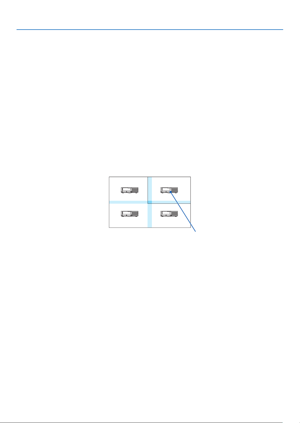
110
5. Using On-Screen Menu
Conditions for using tiling
• Alltheprojectorsneedtofullthefollowingconditions.
• Thepanelsizemustbethesame
• Theprojectionscreensizemustbethesame
• Theleftandrightendsortopandbottomendsoftheprojectionscreenmustbeconsistent.
• Thesettingsfortheleftandrightedgesoftheedgeblendingarethesame
• Thesettingsforthetopandbottomedgesoftheedgeblendingarethesame
Ifthetilingconditionsaresatised,thevideoscreenoftheprojectorateachinstallationpositionwillbeautomati-
callyextractedandprojected.
Ifthetilingconditionsarenotsatised,adjustthevideoscreenoftheprojectorateachinstallationpositionusing
thezoomfunction.
• AssignauniquecontrolIDtoeachprojector.
• Setthe“Colorsetting”and“DeepColorsetting”onyourBlu-rayplayerorcomputerto“Auto”.Refertotheowner's
manualaccompaniedwithyourBlu-rayplayerorcomputerformoreinformation.ConnectanHDMIoutputsignal
ofyourBlu-rayplayerorcomputertotherstprojectorandthenconnecttotheHDBaseTOUT/Ethernetporton
therstprojectortotheHDBaseTIN/Ethernetportonthesecondprojector,sametothesequelprojectors..
Tilingsettingexample)Numberofhorizontalunits=2,Numberofverticalunits=2
Horizontal order = Second unit
Vertical order = First unit
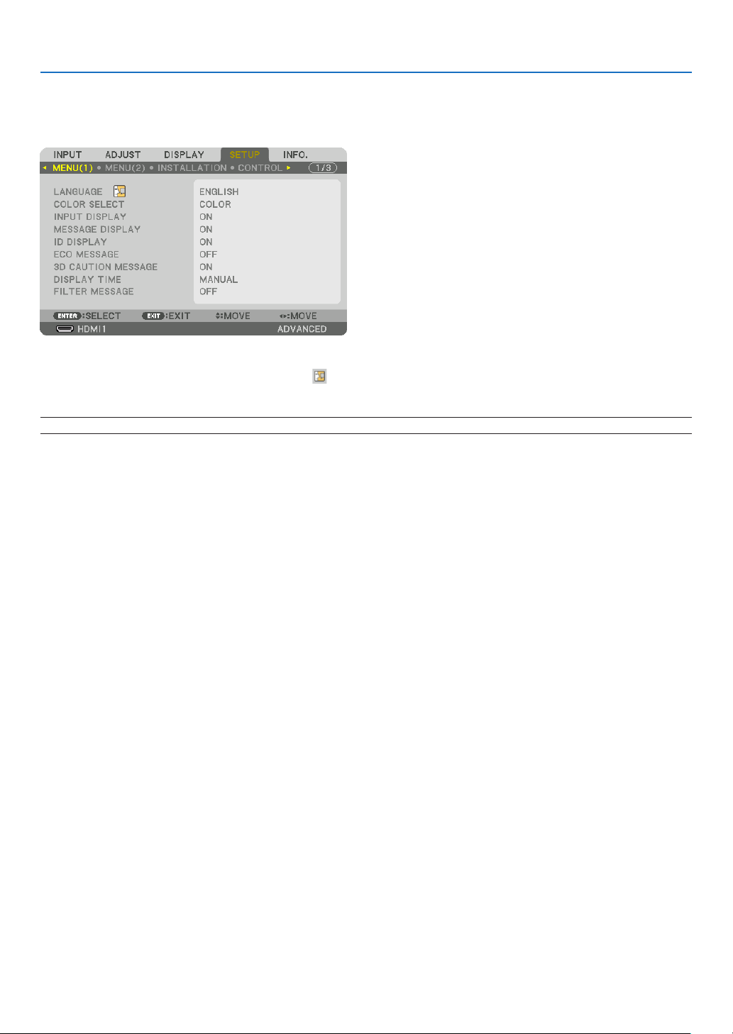
111
5. Using On-Screen Menu
❼ Menu Descriptions & Functions [SETUP]
[MENU(1)]
Selecting Menu Language [LANGUAGE]
Youcanchooseoneof30languagesforon-screeninstructions.
NOTE:Yoursettingwillnotbeaffectedevenwhen[RESET]isdonefromthemenu.
Selecting Menu Color [COLOR SELECT]
Youcanchoosebetweentwooptionsformenucolor:COLORandMONOCHROME.
Turning On / Off Source Display [INPUT DISPLAY]
ThisoptionturnsonoroffinputnamedisplaysuchasHDMI1,HDMI2,DisplayPort,COMPUTER,HDBaseTtobe
displayedonthetoprightofthescreen.
Turning messages on and off [MESSAGE DISPLAY]
Thisoptionselectswhetherornottodisplayprojectormessagesatthebottomoftheprojectedimage.
Evenwhen“OFF”isselected,thesecuritylockwarningisdisplayed.Thesecuritylockwarningturnsoffwhenthe
securitylockiscanceled.
Turning ON/OFF Control ID [ID DISPLAY]
ID DISPLAY ����������� This option turns on or off the ID number which is displayed when the ID SET button on the remote control
is pressed� (→ page 123)
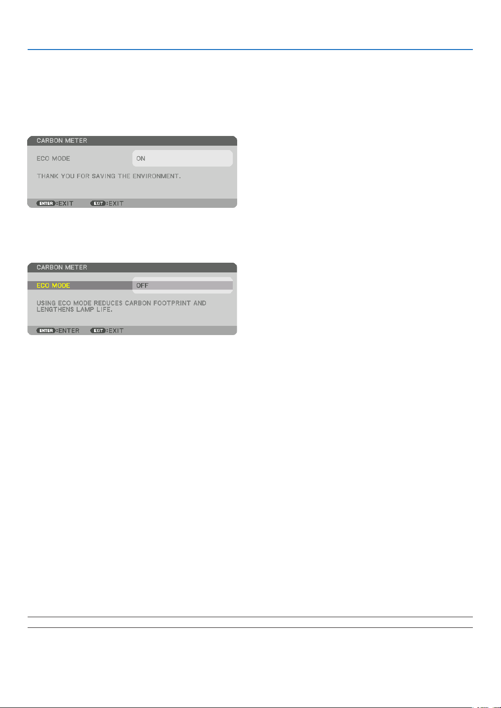
112
5. Using On-Screen Menu
Turning On / Off Eco Message [ECO MESSAGE]
Thisoptionturnsonoroffthefollowingmessageswhentheprojectoristurnedon.
TheEcoMessagepromptstheusertosaveenergy.When[OFF]isselectedfor[ECOMODE],youwillgetamessage
topromptyoutoselect[ON]for[ECOMODE].
When[ON]isselectedfor[ECOMODE]
Toclosethemessage,pressanyoneofthebuttons.Themessagewilldisappearifnobuttonoperationisdonefor
30seconds.
When[OFF]isselectedfor[ECOMODE]
PressingtheENTERbuttonwilldisplaythe[ECOMODE]screen.(→page36)
Toclosethemessage,presstheEXITbutton.
[3D CAUTION MESSAGE]
Thisselectswhethertodisplayacautionmessageornotwhenswitchingtoa3Dvideo.
ThedefaultconditionwhenshippedfromthefactoryisON.
OFF ������������������������ The 3D caution message screen will not be displayed�
ON ������������������������� The 3D caution message screen will be displayed when switching to a 3D video� Press the ENTER button
to cancel the message�
• Themessagewilldisappearautomaticallyafter60secondsorwhenotherbuttonsarepressed.Ifitdisap-
pears automatically, the 3D caution message will be displayed again when switching to a 3D video�
Selecting Menu Display Time [DISPLAY TIME]
Thisoptionallowsyoutoselecthowlongtheprojectorwaitsafterthelasttouchofabuttontoturnoffthemenu.The
presetchoicesare[MANUAL],[AUTO5SEC],[AUTO15SEC],and[AUTO45SEC].The[AUTO45SEC]isthe
factory preset.
Selecting Interval Time for Filter Message [FILTER MESSAGE]
Thisoptionallowsyoutoselectthetimepreferencebetweendisplayingthemessageforcleaningthelters.Clean
thelterwhenyougetthemessage“PLEASECLEANFILTER.”(→page153)
Fiveoptionsareavailable:OFF,100[H],500[H],2000[H],4000[H],5000[H],6000[H],7000[H],10000[H]
Thedefaultsettingis[OFF].
NOTE:Yoursettingwillnotbeaffectedevenwhen[RESET]isdonefromthemenu.

113
5. Using On-Screen Menu
[MENU(2)]
[MENU ANGLE]
Selectthedirectionfordisplayingthemenu.
[MENU POSITION]
Shiftthemenudisplayingposition.
HORISONTAL POSITION �����Shift the menu in the horizontal directions�
VERTICAL POSITION ����������Shift the menu in the vertical directions�
RESET ���������������������������������Reset the menu displaying position to the default factory setting (the screen center)�
TIP
• Oncetheprojectorispoweredoff,themenudisplayingpositionwillresettothedefaultfactorysetting.
• Inputterminalandmessagedisplayingpositionarenotinuencedbythe[MENUPOSITION].
• ItenablestomovethemenubymouseclickwhenacommerciallyavailableUSBmouseisconnected.
• Itenablestomovethemenupositionbythe▼▲◀ and ▶buttonsholdingtopresstheCTLbuttonontheremotecontrolor
mouse click.
• WhiletheMENUPOSITIONoftheon-screenmenuisdisplayedonandthemenuismovedbythe▼▲◀ and ▶ buttons holding
topresstheCTLbuttonontheremotecontrol,theindicationofadjustedvalueonthemenuwillnotbechanged.Inthiscase,
closetheMENUPOSITIONmenuonceanddisplayitagainforindicatingtheadjustedvalueproperly.
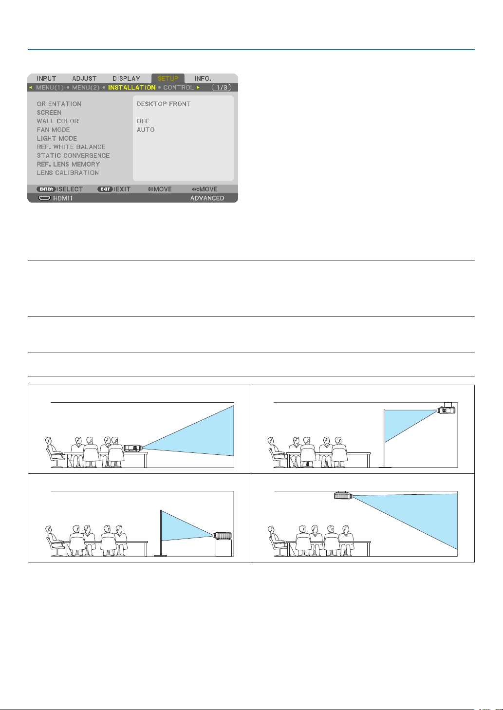
114
5. Using On-Screen Menu
[INSTALLATION]
Selecting Projector Orientation [ORIENTATION]
Thisreorientsyourimageforyourtypeofprojection.Theoptionsare:desktopfrontprojection,ceilingrearprojection,
desktoprearprojection,andceilingfrontprojection.
NOTE:
• Pleaseconsulttheretailstoreifyourequirespecialinstallationservicese.g.whenmountingtheprojectortoaceiling.Neverinstall
the projector on your own. This may result in the projector falling down and causing injury to people.
• Whenusingtheprojectorsuspendedfromaceiling,ensurethatpeopledonotstaybelowtheprojector.Intheeventthelamp
were to break, there is a risk that glass fragments may fall from the projector.
AUTO
��������������������� This automatically detects and projects the DESKTOP FRONT and CEILING FRONT�
NOTE:
• TheDESKTOPREARandCEILINGREARwillnotbedetected.Pleaseselectmanually.
DESKTOPFRONT CEILINGREAR
DESKTOPREAR CEILINGFRONT
TIP:
• CheckwhethertheautomaticDESKTOPFRONTisinstalledwithin±10degreesforoorinstallationandwhethertheCEILING
FRONTiswithin±10degreesforceilinginstallation.Selectmanuallywhentheprojectionscreenisinverted.
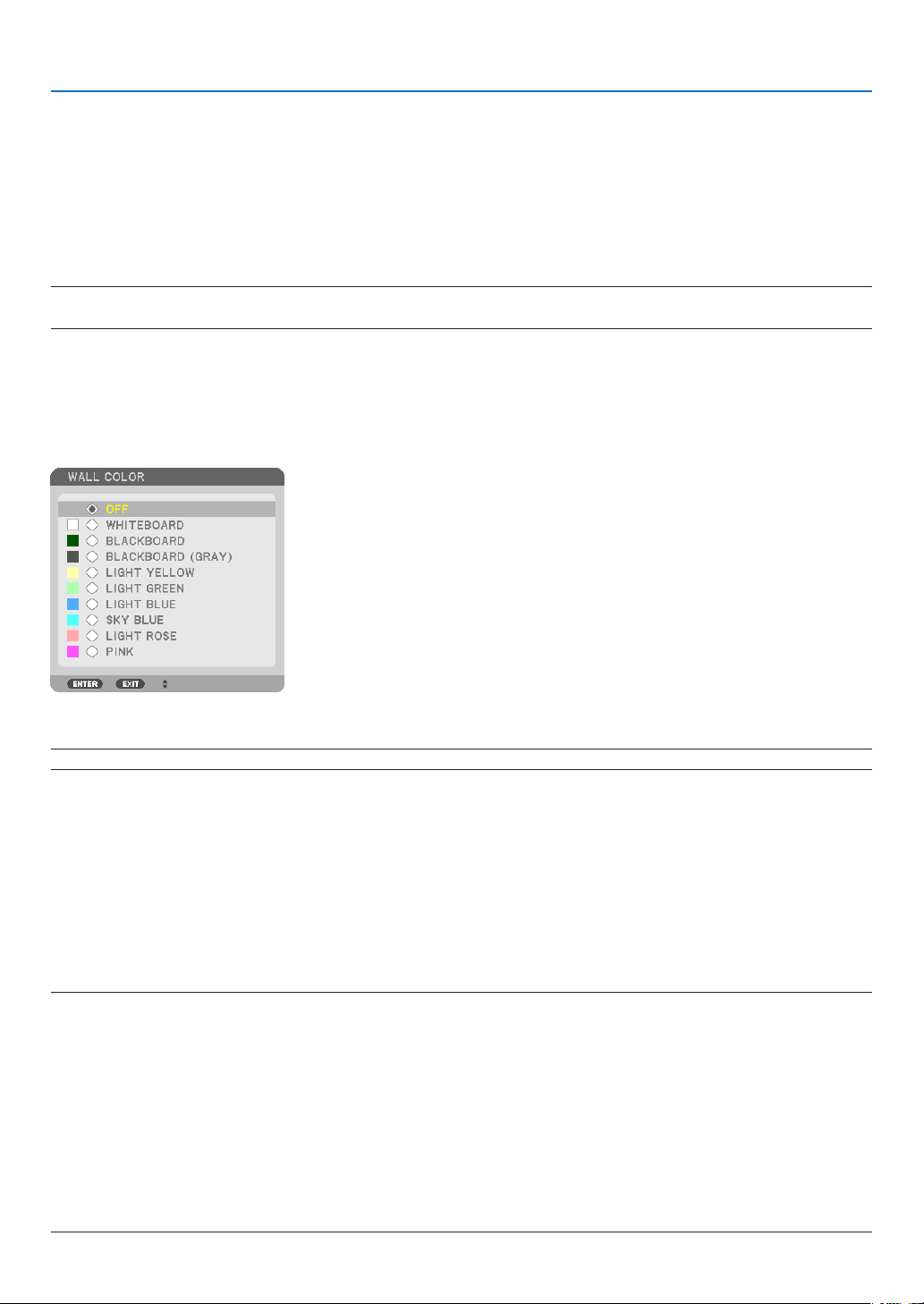
115
5. Using On-Screen Menu
Selecting Aspect Ratio and Position for Screen [SCREEN]
[SCREEN TYPE]
Setstheaspectratiooftheprojectionscreen.
FREE ���������������������� The ratio of the liquid crystal panel is selected� Select this when projecting multi-screen and 17:9 screen
(2K)�
4:3 SCREEN ����������� For a screen with a 4:3 aspect ratio
16:9 SCREEN
��������� For a screen with a 16:9 aspect ratio
16:10 SCREEN
������� For a screen with a 16:10 aspect ratio
NOTE:
•
Afterchangingthescreentype,checkthesettingof[ASPECTRATIO]inthemenu.(→ page 94)
[POSITION]
Adjustthescreenposition.Dependingonthemodelyouuseandthescreentype,thefunctionmaybecomeineffec-
tiveandtheadjustablerangemayvary.
Using the Wall Color Correction [WALL COLOR]
Thisfunctionallowsforquickadaptivecolorcorrectioninapplicationswherethescreenmaterialisnotwhite.
NOTE:Selecting[WHITEBOARD]reduceslampbrightness.
Selecting Fan Mode [FAN MODE]
FanModeisusedtosetthespeedoftheinternalcoolingfan.
MODE �������������������� Select one among four modes: AUTO, NORMAL, HIGH, and HIGH ALTITUDE�
AUTO: The built-in fans automatically run at variable speed according to the detected temperature and
atmospheric pressure by the built-in sensor�
NORMAL: The built-in fans run at the appropriate speed based on the detection by the built-in temperature
sensor�
HIGH: The built-in fans run at high speed
HIGH ALTITUDE: The built-in fans run at high speed� Select this option when using the projector at altitudes
approximately 5500 feet/1700 meters or higher�
NOTE:
• Makesurethespeedissetto[HIGH]whenyouareusingthisdevicecontinuouslyforseveraldays.
•Set[FANMODE]to[AUTO]or[HIGHALTITUDE]whenusingtheprojectorataltitudesapproximately5500feet/1700metersor
higher.
• Usingtheprojectorataltitudesapproximately5500feet/1700metersorhigherwithoutsettingto[AUTO]or[HIGHALTITUDE]
can cause the projector to overheat and the protector could shut down. If this happens, wait a couple minutes and turn on the
projector.
•Usingtheprojectorataltitudeslessthanapproximately5500feet/1700metersandsettingto[HIGHALTITUDE]cancausethe
lamptoovercool,causingtheimagetoicker.Switch[FANMODE]to[AUTO].
•Usingtheprojectorataltitudesapproximately5500feet/1700metersorhighercanshortenthelifeofopticalcomponentssuch
as the lamp.
• Yoursettingwillnotbeaffectedevenwhen[RESET]isdonefromthemenu.
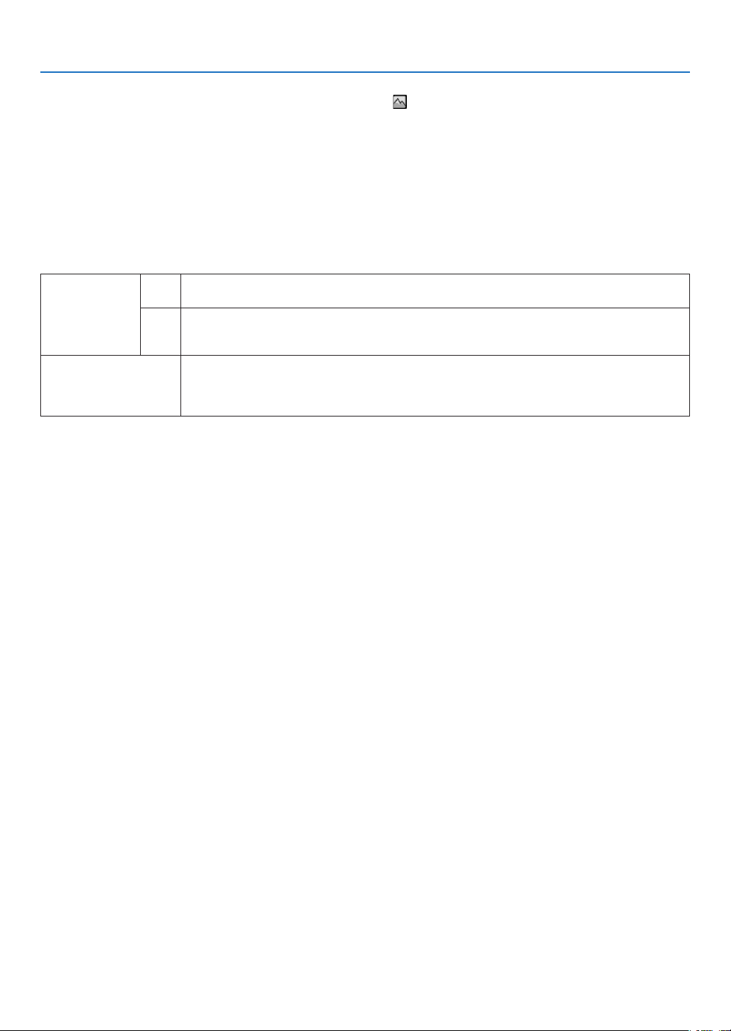
116
5. Using On-Screen Menu
TIP:
• When[HIGHALTITUDE]isselectedfor[FANMODE],asymbolicon will be displayed at the bottom of the menu.
[LIGHT MODE]
Wheneco-modeissetto[ON],theCO
2
emissions(calculatedfromthereductioninpowerconsumption)oftheprojec-
torcanbereduced.Theeco-modereducespowerconsumptionbymainlyloweringthebrightnessofthelamp.Asa
result,thelampreplacementtime(asaguide)*isextended.(→page37,136)
* Replacementtimenotguaranteed.
REF� LIGHT ������������ This can be set when the eco-mode is set to [OFF]� Adjust the lamp to match the brightness of each projector
when projecting a multi-screen display using multiple projectors�
ECOMODE OFF Thelampluminance(brightness)willbecome100%andthescreenwillturnbright.
Theluminanceofthelampcanbesetusingthelampadjustment.
ON Thelampluminance(brightness)willbecomeapproximately70%andthelampreplacementtime
(estimated)*willbeextended.
* Thereplacementtimeisnotguaranteed.
REF.LIGHT Whenthe[MODE]forthe[PICTURE]inthe[ADJUST]is[STANDARD],andthe[ECOMODE]is
setto[OFF],[REF.LIGHT]isenabled.
Adjustthelamptomatchthebrightnessofeachprojectorwhenprojectingamulti-screendisplay
usingmultipleprojectors.
[REF. WHITE BALANCE]
Thisfeatureallowsyoutoadjustthewhitebalanceforallsignals.
Thewhiteandblacklevelsofthesignalareadjustedforoptimumcolorreproduction.
Uniformityisalsoadjustedwhentheredness(R)andblueness(B)ofthewhitecolorinthescreen’shorizontal(left/
right)directionareuneven.
CONTRAST R/CONTRAST G/CONTRAST B
������������������������������ These adjust the picture’s white color�
BRIGHTNESS R/BRIGHTNESS G/BRIGHTNESS B
������������������������������ These adjust the picture’s black color�
UNIFORMITY R ������ The further this is set to the + side, the stronger the redness on the left side of the picture (increasing
towards the left edge) and the weaker the redness on the right side of the picture (decreasing towards the
right edge)�
This is reversed when set to the – side�
UNIFORMITY B ������ The further this is set to the + side, the stronger the blueness on the left side of the picture (increasing
towards the left edge) and the weaker the blueness on the right side of the picture (decreasing towards the
right edge)�
This is reversed when set to the – side�
[STATICCONVERGENCE]
Thisfeaturesallowsyoutoadjustforcolordeviationinthepicture.
Thiscanbeadjustedinunitsof±1pixelinthehorizontaldirectionforHORIZONTALR,GandB,intheverticaldirec-
tionforVERTICALR,GandB.

117
5. Using On-Screen Menu
Using the Reference Lens Memory Function [REF. LENS MEMORY]
ThisfunctionservestostoretheadjustedvaluescommontoallinputsourceswhenusingtheLENSSHIFT,ZOOM
andFOCUSbuttonsoftheprojectorortheremotecontrol.Theadjustedvaluesstoredinmemorycanbeusedasa
reference to the current.
PROFILE ���������������� Select a stored [PROFILE] number�
STORE ������������������� Stores the current adjusted values in memory as a reference�
MOVE �������������������� Applies the adjusted reference values stored in [STORE] to the current signal�
RESET �������������������� Reset selected [PROFILE] number [REF� LENS MEMORY] to the factory default settings�
LOAD BY SIGNAL �� When you switch signals the lens will shift to the lens shift, zoom, and focus values for the selected [PRO-
FILE] number�
If no adjusted values have been saved to [LENS MEMORY], the lens will apply [REF� LENS MEMORY]
adjusted values� Alternatively, if no adjusted values have been saved to [REF� LENS MEMORY], the unit will
return to factory default settings�
FORCED MUTE ������ To turn off the image during lens shift, select [YES]�
• ThelensunitsNP11FL,NP12ZL,NP13ZL,NP14ZL,andNP30ZLdonotsupportthisfunction.
NOTE:
• Adjustedvaluesin[REF.LENSMEMORY]willnotbereturnedtodefaultwhenperforming[CURRENTSIGNAL]or[ALLDATA]for
[RESET]fromthemenu.
• Tostoreadjustedvaluesforeachinputsource,usetheLensMemoryfunction.(→ page 56, 99)
[LENS CALIBRATION]
Theadjustmentrangeofthezoom,focus,andshiftofthemountedlensiscalibrated.
Besuretocarryout[LENSCALIBRATION]afterreplacingthelens.
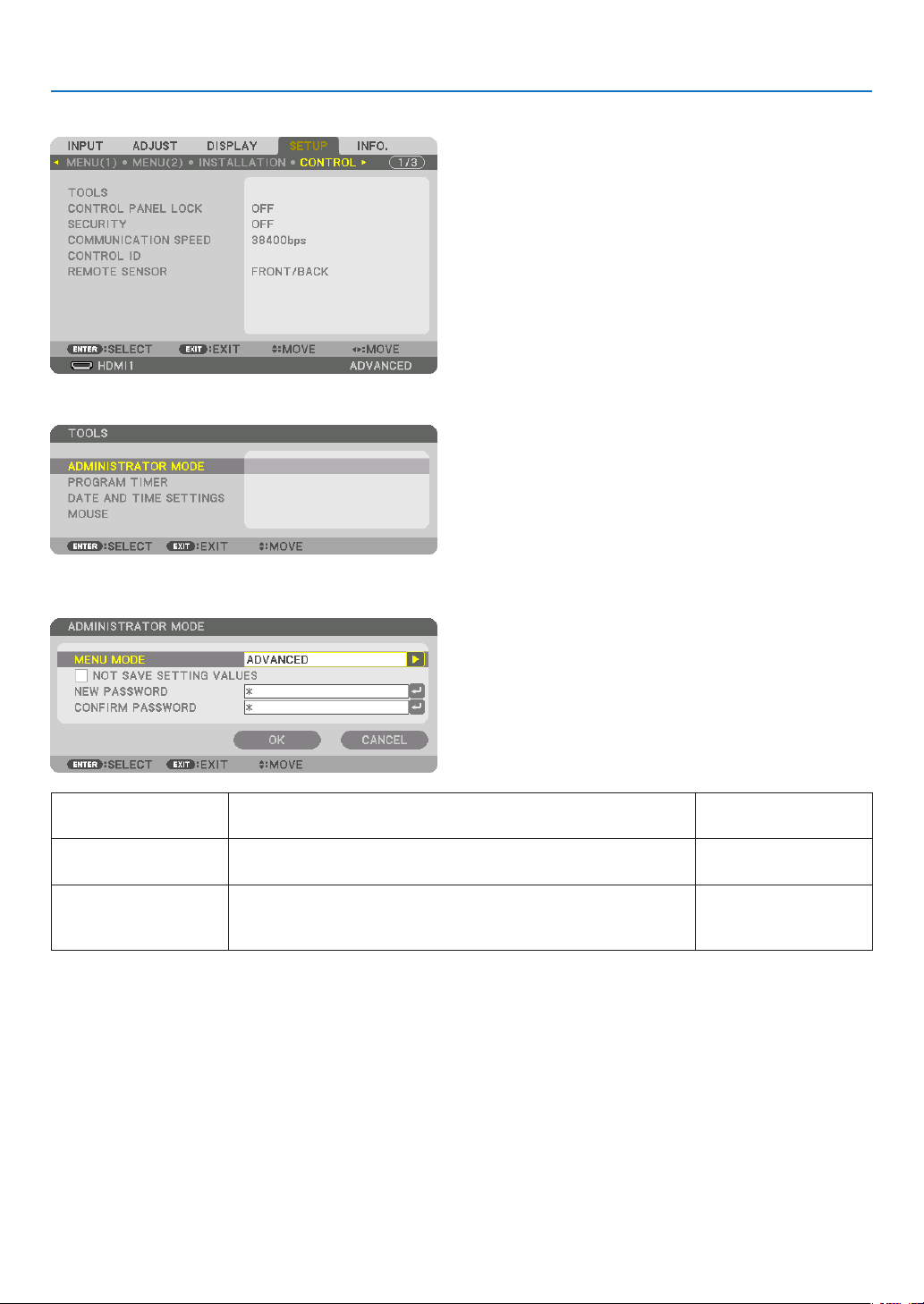
118
5. Using On-Screen Menu
[CONTROL]
TOOLS
ADMINISTRATOR MODE
ThisallowsyoutoselectMENUMODE,savesettings,andsetapasswordfortheadministratormode.
MENUMODE Selecteither[BASIC]or[ADVANCED]menu.
(→page78)
—
NOTSAVESETTING
VALUES
Placingacheckmarkwillnotsaveyourprojectorsettings.
Clearthischeckboxtosaveyourprojectorsettings.
—
NEWPASSWORD/
CONFIRMPASS-
WORD
Assignapasswordfortheadministratormode. Upto10alphanumeric
characters
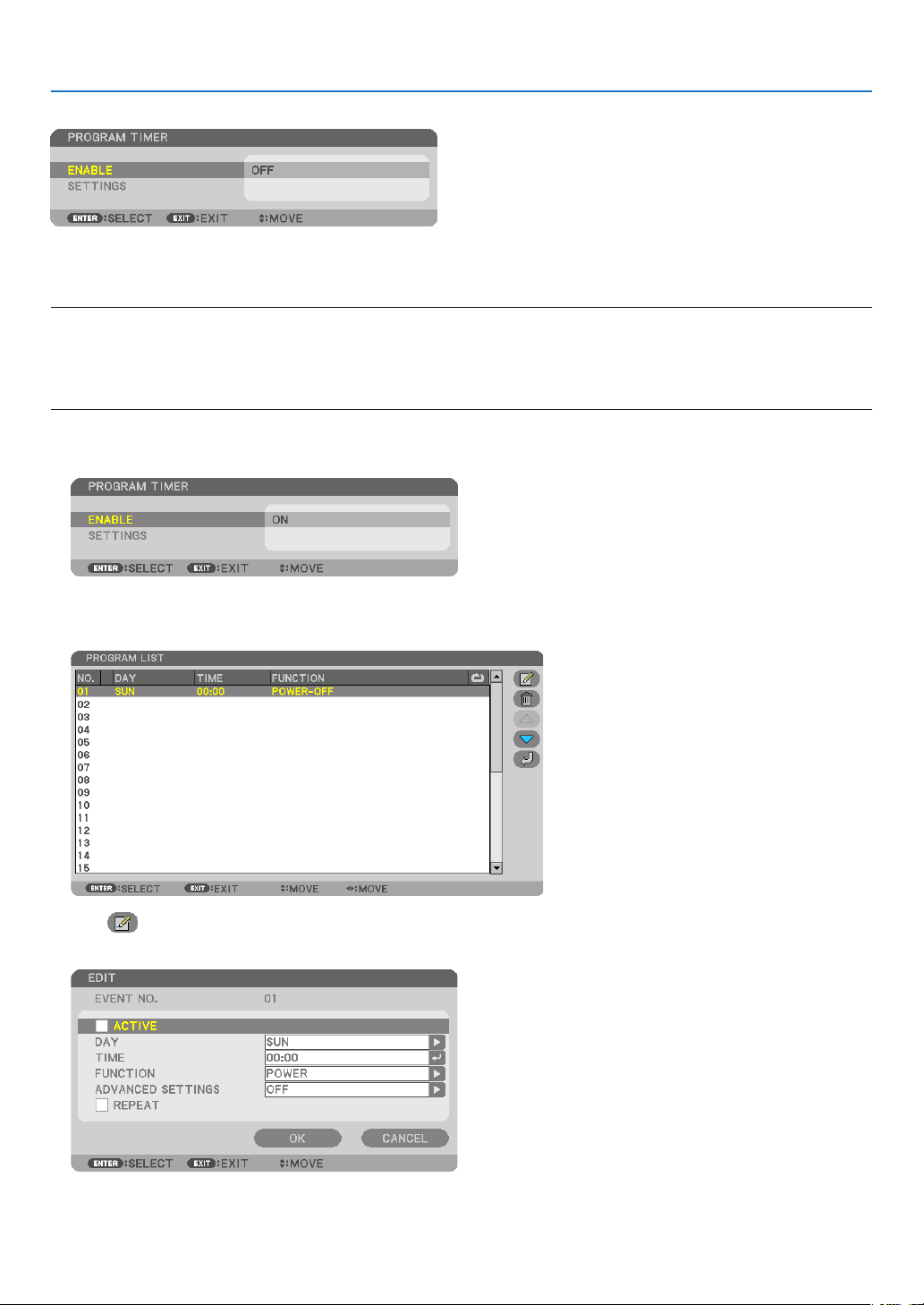
119
5. Using On-Screen Menu
PROGRAM TIMER
Thisoptionturnson/standbytheprojectorandchangesvideosignals,andselectsLIGHTmodeautomaticallyata
speciedtime.
NOTE:
• Beforeusing[PROGRAMTIMER],makesurethatthe[DATEANDTIME]featureisset.(→ page 122)
MakesurethattheprojectorisinthestandbyconditionwiththePOWERcordconnected.
The projector has a built-in clock. The clock will keep working for about a month after the main power is turned off. If the main
powerisnotsuppliedtotheprojectorforamonthormore,itrequirestoset[DATEANDTIMESETTINGS]featureagain.
Setting a new program timer
1. OnthePROGRAMTIMERscreen,usethe▲ or ▼buttontoselect[SETTINGS]andpresstheENTERbutton.
The [PROGRAM LIST] screen will be displayed.
2. SelectablankprogramnumberandpresstheENTERbutton.
The [ (EDIT)] screen will be displayed.
3. Makesettingsforeachitemasrequired.
ACTIVE ������������������ Place a check mark to enable the program�
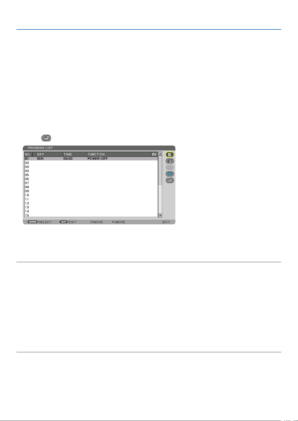
120
5. Using On-Screen Menu
DAY ������������������������ Select days of the week for the program timer� To execute the program from Monday to Friday, select [MON-
FRI]� To execute the program in everyday basis, select [EVERYDAY]�
TIME ���������������������� Set the time to execute the program� Enter time in 24-hour format�
FUNCTION ������������� Select a function to be executed� Selecting [POWER] will allow you to turn on or off the projector by setting
[ADVANCED SETTINGS]� Selecting [INPUT] will allow you to select a video source by setting [ADVANCED
SETTINGS]� Selecting [ECO MODE] will allow you to select ON or OFF for [ECO MODE] by setting [ADVANCED
SETTINGS]�
ADVANCED SETTINGS
������������������������������ Select power on/off, a type of video source, or ECO MODE for the selected item in [FUNCTION]�
REPEAT ������������������ Place a check mark to repeat the program continuing basis� To use the program this week only, clear the
check mark�
4. Select[OK]andpresstheENTERbutton.
This will complete the settings.
You will be returned to the [PROGRAM LIST] screen.
5. Select[ (BACK)]andpresstheENTERbutton.
You will be returned to the [PROGRAM TIMER] screen.
6. Select[EXIT]andpresstheENTERbutton.
You will be returned to the [TOOLS] screen.
NOTE:
• Upto30differenttimersettingscanbeprogrammed.
• TheProgramTimerisexecutedonasettimebasis,notinaprogrambasis.
• Oncetheprogramnotmarkedwithacheckin[REPEAT]hasbeenexecuted,thecheckmarkinthe[ACTIVE]checkboxwillbe
cleared automatically and the program will be disabled.
• Whentheon-timeandtheoff-timesetforthesametime,theoff-timesettingwilltakepreference.
• Whentwodifferentsourcesaresetforthesametime,thelargerprogramnumberwilltakepreference.
• Theon-timesettingwillnotbeexecutedwhilethecoolingfansarerunningoranerrorisoccurring.
• Iftheoff-timesettingisexpiredundertheconditioninwhichthepoweroffisnotpossible,theoff-timersettingwillnotbeexecuted
until the power off becomes possible.
• Programsnotmarkedwithacheckmarkin[ACTIVE]ofthe[EDIT]screenwillnotbeexecutedeveniftheProgramTimeris
enabled.
• Whentheprojectoristurnedonbyusingtheprogramtimerandifyouwanttoturnofftheprojector,settheoff-timeordoit
manually so as not to leave the projector on for a long period of time.

121
5. Using On-Screen Menu
Activating the program timer
1. Select[ENABLE]onthe[PROGRAMTIMER]screenandpresstheENTERbutton.
The selection screen will be displayed.
2. Press the ▼buttontoalignthecursorwith[ON]andthenpresstheENTERbutton.
Return to the [PROGRAM TIMER] screen.
NOTE:
• Whentheeffectivesettingsofthe[PROGRAMTIMER]havenotbeensetto[ON],theprogramwillnotbeexecutedevenifthe
[ACTIVE]itemsintheprogramlisthavebeenticked.
• Evenwhentheeffectivesettingsofthe[PROGRAMTIMER]aresetto[ON],the[PROGRAMTIMER]willnotworkuntilthe[PRO-
GRAMTIMER]screenisclosed.
Editing the programmed settings
1. Onthe[PROGRAMLIST]screen,selectaprogramyouwanttoeditandpresstheENTERbutton.
2. Changethesettingsonthe[EDIT]screen.
3. Select[OK]andpresstheENTERbutton.
The programmed settings will be changed.
You will be returned to the [PROGRAM LIST] screen.
Changing the order of programs
1. Onthe[PROGRAMLIST]screen,selectaprogramwhoseorderyouwanttochangeandpressthe▶ button.
2. Press the ▼ button to select ▲ or ▼.
3. PresstheENTERbuttonafewtimestoselectarowtowhichyouwishtomovetheprogram.
The order of the programs will be changed.
Deleting the programs
1. Onthe[PROGRAMLIST]screen,selectaprogramnumberyouwanttodeleteandpressthe▶ button.
2. Press the ▼buttontoselect[ (DELETE)].
3. PresstheENTERbutton.
The confirmation screen will be displayed.
4. Select[YES]andpresstheENTERbutton.
The program will be deleted.
This will complete deleting the program.

122
5. Using On-Screen Menu
DATE AND TIME SETTINGS
Youcansetthecurrenttime,month,date,andyear.
NOTE: The projector has a built-in clock. The clock will keep working for about a month after the main power is turned off. If the
main power is off for a month or more, the built-in clock will cease. If the built-in clock ceases, set the date and time again. The
built-in clock will not cease while in the standby mode. In order to activate the built-in clock continuously even when the projector
is not used, leave it in the standby state not plugging off the power cord.
TIME ZONE SETTINGS
�������������� Select your time zone�
DATE AND TIME SETTINGS ������ Set your current date (MM/DD/YYYY) and time (HH:MM)�
INTERNET TIME SERVER: If you place a check mark, the projector’s built-in clock will be syn-
chronized with an Internet time server in every 24 hours and at the time of projector’s startup�
UPDATE: Synchronizes the projector’s built-in clock immediately� The UPDATE button is not
available unless the INTERNET TIME SERVER check box is turned on�
SUMMER TIME SETTINGS ������� If you place a check mark, the clock for daylight saving will be enabled�
[MOUSE]
ThisfunctionisforusingacommerciallyavailableUSBmouseviatheUSB-Aportonthisprojector.
BUTTON ����������������� Select for using the mouse either by right or left hand�
SENSITIVITY ���������� Select the sensitivity of mouse among FAST, MIDDLE and LOW�
NOTE:ThissettingisnotguaranteedmotionofallcommerciallyavailableUSBmouses.
Disabling the Cabinet Buttons [CONTROL PANEL LOCK]
ThisoptionturnsonorofftheCONTROLPANELLOCKfunction.
NOTE:
• Howtocancelthe[CONTROLPANELLOCK]
Whenthe[CONTROLPANELLOCK]issetto[ON],presstheINPUTbuttononthemainbodyforabout10secondstocancelthe
[CONTROLPANELLOCK]setting.
TIP:
• Whenthe[CONTROLPANELLOCK]isturnedon,akeylockicon[ ]willbedisplayedatthebottomrightofthemenu.
• ThisCONTROLPANELLOCKdoesnotaffecttheremotecontrolfunctions.
Enabling Security [SECURITY]
ThisfeatureturnsonorofftheSECURITYfunction.
Unlessthecorrectkeywordisentered,theprojectorcannotprojectanimage.(→page43)
NOTE:Yoursettingwillnotbeaffectedevenwhen[RESET]isdonefromthemenu.
Selecting Communication Speed [COMMUNICATION SPEED]
ThisfeaturesetsthecommunicationspeedforthePCControlport(D-Sub9P).Makesuretosettheappropriate
speed for the device to connect.
NOTE:
• Yourselectedcommunicationspeedwillnotbeaffectedevenwhen[RESET]isdonefromthemenu.
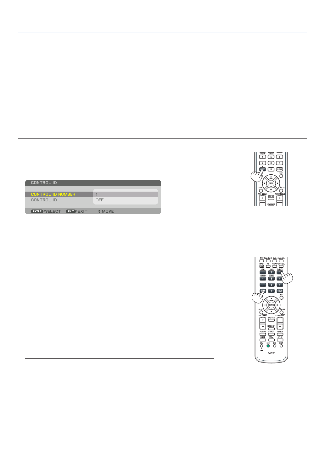
123
5. Using On-Screen Menu
Setting ID to the Projector [CONTROL ID]
YoucanoperatemultipleprojectorsseparatelyandindependentlywiththesingleremotecontrolthathastheCONTROL
IDfunction.IfyouassignthesameIDtoalltheprojectors,youcanconvenientlyoperatealltheprojectorstogether
usingthesingleremotecontrol.Todoso,youhavetoassignanIDnumbertoeachprojector.
CONTROL ID NUMBER ������� Select a number from 1 to 254 you wish to assign to your projector�
CONTROL ID �����������������������Select [OFF] to turn off the CONTROL ID setting and select [ON] to turn on the CONTROL ID setting�
NOTE:
• When[ON]isselectedfor[CONTROLID],theprojectorcannotbeoperatedbyusingtheremotecontrolthatdoesnotsupport
theCONTROLIDfunction.(Inthiscasethebuttonsontheprojectorcabinetcanbeused.)
• Yoursettingwillnotbeaffectedevenwhen[RESET]isdonefromthemenu.
•PressingandholdingtheENTERbuttonontheprojectorcabinetfor10secondswilldisplaythemenuforcancelingtheControl
ID.
Assigning or Changing the Control ID
1. Turnontheprojector.
2. PresstheIDSETbuttonontheremotecontrol.
The CONTROL ID screen will be displayed.
If the projector can be operated with the current remote control ID, the [AC-
TIVE] will be displayed. If the projector cannot be operated with the current
remote control ID, the [INACTIVE] will be displayed. To operate the inactive
projector, assign the control ID used for the projector by using the following
procedure (Step 3).
3. PressoneofnumerickeypadbuttonswhilepressingandholdingtheID
SETbuttonontheremotecontrol.
Example:
To assign “3”, press the “3” button on the remote control.
No ID means that all the projectors can be operated together with a single
remote control. To set “No ID”, enter “000” or press the CLEAR button.
TIP:TherangeofIDsisfrom1to254.
4. ReleasetheIDSETbutton.
The updated CONTROL ID screen will be displayed.
NOTE:
•TheIDscanbeclearedinafewdaysafterthebatteriesarerundownorremoved.
•Accidentallypressinganyoneofthebuttonsoftheremotecontrolwillclearcurrently
speciedIDwithbatteriesremoved.

124
5. Using On-Screen Menu
Turning On or Off Remote Sensor [REMOTE SENSOR]
Thisoptiondetermineswhichremotesensorontheprojectorisenabledinwirelessmode.
Theoptionsare:FRONT/BACK,FRONT,BACK,andHDBaseT*.
NOTE:
• TheremotecontroloftheprojectorwillnotbeabletoreceivesignalsifthepowersupplyoftheHDBaseTtransmissiondevice
connectedtotheprojectorisswitchedonwhenthishasbeensetto“HDBaseT”.
TIP:
• Iftheremotecontrolsystemdoesnotfunctionwhendirectsunlightorstrongilluminationstrikestheremotecontrolsensorof
the projector, change to other option.

125
5. Using On-Screen Menu
[NETWORK SETTINGS]
Important:
• Consultwithyournetworkadministratoraboutthesesettings.
• WhenusingawiredLAN,connecttheEthernetcable(LANcable)totheLANportontheprojector.(→ page 152)
• Pleaseuseashieldedtwistedpair(STP)cableofCategory5eorhigherfortheLANcable(soldcommercially).
TIP:Thenetworksettingsyoumakewillnotbeaffectedevenwhen[RESET]isdonefromthemenu.
Hints on How to Set Up LAN Connection
To set up the projector for a LAN connection:
Select[WIREDLAN]→[PROFILES]→[PROFILE1]or[PROFILE2].
TwosettingscanbesetforwiredLAN.
Nextturnonorofffor[DHCP],[IPADDRESS],[SUBNETMASK],and[GATEWAY]andselect[OK]andpressthe
ENTERbutton.(→page126)
TorecallLANsettingsstoredintheprolenumber:
Select[PROFILE1]or[PROFILE2]forwiredLAN,andthenselect[OK]andpresstheENTERbutton.(→page126)
To connect a DHCP server:
Turnon[DHCP]forwiredLAN.Select[ON]andpresstheENTERbutton.TospecifyIPaddresswithoutusingthe
DHCPserver,turnoff[DHCP].(→page126)
To receive lamp replacement time or error messages via e-mail:
Select[ALERTMAIL],andset[SENDER'SADDRESS],[SMTPSERVERNAME],and[RECIPIENT'SADDRESS].
Last,select[OK]andpresstheENTERbutton.(→page128)

126
5. Using On-Screen Menu
WIRED LAN
INTERFACE Select[LAN]forusingtheLANportforconnectingtothewired
LAN.Select[HDBaseT]forusingtheHDBaseTIN/Ethernetport
forconnectingtothewiredLAN.Thecontrolfromtheconnected
devicewillbedisabledifnosignalissentandreceivedforthree
minutesiftheprojectorisconnectedtowiredLANthrutheHD-
BaseTIN/Ethernet.For refusingthis,setthestandbymodeto
[SLEEP]inadvance.
—
PROFILES
• ThesettingsforthewiredLANcanberecordedintheprojector
memory in two ways.
• Select[PROFILE1]or[PROFILE2]andthendosettingsfor
[DHCP]andtheotheroptions.
Afterdoingthis,select[OK]andpresstheENTERbutton.This
willstoreyoursettingsinmemory.
• Torecallthesettingsfrommemory:
Afterselecting[PROFILE1]or[PROFILE2]fromthe[PRO-
FILES]list.
Select[OK]andpresstheENTERbutton.
• Select[DISABLE]whennotconnectingtoawiredLAN
—
DHCP
PlaceacheckmarktoautomaticallyassignanIPaddresstothe
projectorfromyourDHCPserver.
ClearthischeckboxtoregistertheIPaddressorsubnetmask
numberobtainedfromyournetworkadministrator.
—
IPADDRESS SetyourIPaddressofthenetworkconnectedtotheprojector
when[DHCP]isturnedoff.
Upto12numeric
characters
SUBNETMASK Setyoursubnetmasknumberofthenetworkconnectedtothe
projectorwhen[DHCP]isturnedoff.
Upto12numeric
characters
GATEWAY
Setthedefaultgatewayofthenetworkconnectedtotheprojector
when[DHCP]isturnedoff.
Upto12numeric
characters
AUTODNS PlaceacheckmarktoautomaticallyassigntheIPaddressofyour
DNSserverconnectedtotheprojectorfromyourDHCPserver.
ClearthischeckboxtosettheIPaddressofyourDNSserver
connected to the projector.
Upto12numeric
characters
DNSCONFIGURA-
TION
SettheIPaddressofyourDNSserveronthenetworkconnected
totheprojectorwhen[AUTODNS]iscleared.
Upto12numeric
characters
RECONNECT
Retrytoconnecttheprojectortoanetwork.Trythisifyouhave
changed[PROFILES].
—
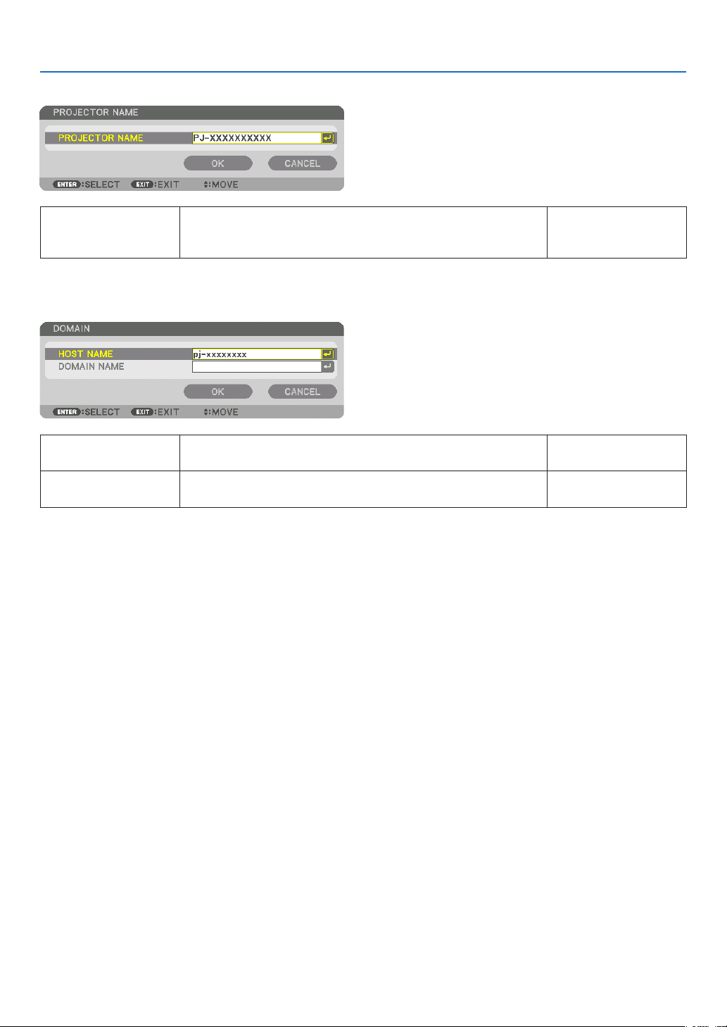
127
5. Using On-Screen Menu
PROJECTORNAME
PROJECTORNAME Setauniqueprojectorname. Upto16alphanu-
meric characters and
symbols
DOMAIN
Setahostnameanddomainnameoftheprojector.
HOSTNAME Setahostnameoftheprojector. Upto16alphanumeric
characters
DOMAINNAME Setadomainnameoftheprojector. Upto60alphanumeric
characters
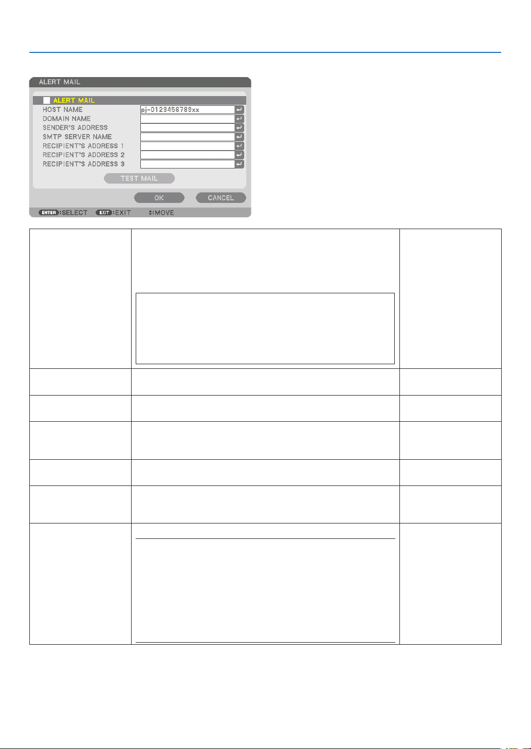
128
5. Using On-Screen Menu
ALERT MAIL
ALERTMAIL Thisoptionwillnotifyyourcomputeroflampreplacetimeorerror
messagesviae-mailwhenusingwirelessorwiredLAN.
Placing a checkmark will turn on the Alert Mail feature�
Clearing a checkmark will turn off the Alert Mail feature�
Sample of a message to be sent from the projector:
Thelamphasreachedtheendofitsusablelife.
Please replace the lamp.
Usethespeciedlampforsafetyandperformance.
[Information]
ProjectorName:xxxxx
LampHoursUsed:xxxxx[H]
—
HOSTNAME Typeinahostname. Upto16alphanumeric
characters
DOMAINNAME Typeinadomainnameofthenetworkconnectedtotheprojector. Upto60alphanumeric
characters
SENDER'SAD-
DRESS
Specifythesender’saddress. Upto60alphanu-
meric characters and
symbols
SMTPSERVER
NAME
TypeintheSMTPservernametobeconnectedtotheprojector. Upto60alphanumeric
characters
RECIPIENT'SAD-
DRESS1,2,3
Typeinyourrecipient’saddress. Upto60alphanu-
meric characters and
symbols
TESTMAIL Sendatestmailtocheckifyoursettingsarecorrect.
NOTE:
• Ifyouenteredanincorrectaddressinatest,youmaynotreceivean
Alert mail. Should this happen, checkif the Recipient’s Address is
correctly set.
• Unless any one of the[SENDER'S ADDRESS], [SMTP SERVER'S
NAME]or[RECIPIENT'SADDRESS1-3]isselected,[TESTMAIL]is
not available.
• Besuretohighlight[OK]andpresstheENTERbuttonbeforeexecuting
[TESTMAIL].
—

129
5. Using On-Screen Menu
NETWORKSERVICE
HTTPSERVER SetapasswordforyourHTTPserver. Upto10alphanumeric
characters
PJLink
This option allows you to set a password when you use the
PJLinkfeature.
NOTE:
• Donotforgetyourpassword.However,ifyouforgetyourpassword,
consult with your dealer.
• WhatisPJLink?
PJLinkisastandardizationofprotocolusedforcontrollingprojectors
of different manufacturers. This standard protocol is established by
JapanBusinessMachineandInformationSystemIndustriesAssocia-
tion(JBMIA)in2005.
TheprojectorsupportsallthecommandsofPJLinkClass1.
• SettingofPJLinkwillnotbeaffectedevenwhen[RESET]isdonefrom
the menu.
Upto32alphanumeric
characters
AMXBEACON TurnonorofffordetectionfromAMXDeviceDiscoverywhen
connectingtothenetworksupportedbyAMX’sNetLinxcontrol
system.
TIP:
WhenusingadevicethatsupportsAMXDeviceDiscovery,allAMXNetLinx
control system will recognize the device and download the appropriate
DeviceDiscoveryModulefromanAMXserver.
Placing a checkmark will enable detecting the projector from AMX Device
Discovery�
Clearing a checkmark will disable detecting the projector from AMX
Device Discovery�
—
CRESTRON
ROOMVIEW:Turnonoroffwhencontrollingtheprojectorfrom
yourPC.
CRESTRON CONTROL: Turn on or off when controlling the
projector from your controller.
• CONTROLLERIPADDRESS:EnteryourIPaddressofCREST-
RONSERVER.
• IPID:EnteryourIPIDofCRESTRONSERVER.
Upto12numeric
characters
ExtronXTP SetforconnectingthisprojectortotheExtronXTPtransmitter.ON
willenabletoconnectwiththeXTPtransmitter.OFFwilldisable
toconnectwiththeXTPtransmitter.
—
TIP:TheCRESTRONsettingsarerequiredonlyforusewithCRESTRONROOMVIEW.
Formoreinformation,visithttp://www.crestron.com

130
5. Using On-Screen Menu
[SOURCE OPTIONS]
SettingAutoAdjust[AUTOADJUST]
ThisfeaturesetstheAutoAdjustmodesothatthecomputersignalcanbeautomaticallyormanuallyadjustedfor
noiseandstability.Youcanautomaticallymakeadjustmentintwoways:[NORMAL]and[FINE].
OFF ������������������������ The computer signal will not be automatically adjusted� You can manually optimize the computer signal�
NORMAL ���������������� Default setting� The computer signal will be automatically adjusted� Normally select this option�
FINE ����������������������� Select this option if fine adjustment is needed� It takes more time to switch to the source than when [NOR-
MAL]is selected�
TIP:
• Thedefaultsettingwhenshippedfromthefactoryis[NORMAL].
• WhentheAUTOADJ.buttonispressed,thesame[FINE]adjustmentiscarriedout.
[AUDIO SELECT]
ThisselectstheaudioinputoftheHDMI1INterminal,HDMI2INterminal,DisplayPortinputterminalandHDBaseT
IN/Ethernetport.
Selecting Default Source [DEFAULT INPUT SELECT]
Youcansettheprojectortodefaulttoanyoneofitsinputseachtimetheprojectoristurnedon.
LAST ���������������������� Sets the projector to default to the previous or last active input each time the projector is turned on�
AUTO ��������������������� Searches for an active source in order of HDMI1 → HDMI2 → DisplayPort → COMPUTER → HDBaseT and
displays the first found source�
HDMI1 ������������������� Displays the digital source from the HDMI 1 IN connector every time the projector is turned on�
HDMI2 ������������������� Displays the digital source from the HDMI 2 IN connector every time the projector is turned on�
DisplayPort ������������ Displays the digital source from the DisplayPort every time the projector is turned on�
COMPUTER ����������� Displays the computer signal from the COMPUTER IN connector every time the projector is turned on�
HDBaseT ���������������� Project the HDBaseT signal�
[SEAMLESS SWITCHING]
Whentheinputconnectorisswitched,theimagedisplayedbeforeswitchingisheldtoswitchtothenewimagewithout
abreakduetoabsenceofasignal.
Selecting a Color or Logo for Background [BACKGROUND]
Usethisfeaturetodisplayablue/blackscreenorlogowhennosignalisavailable.Thedefaultbackgroundis[BLUE].
NOTE:
• Evenwhenthebackgroundlogoisselected,iftwopicturesaredisplayedin[PIP/PICTUREBYPICTURE]mode,thebluebackground
is displayed without the logo when there is no signal.

131
5. Using On-Screen Menu
[HDBaseT OUT SELECT]
SelectsignaltooutputfromtheHDBaseTOUT/Ethernetportontheprojector.Whentwoimagesareprojectedsimul-
taneously(PIP/PICTUREBYPICTURE),theimageforthemainscreenisoutput.
AUTO ��������������������� Output the input signal� When [PIP] has been set, the input signal for the main screen is output�
HDMI1 ������������������� Output the input signal thru the HDMI1 input terminal�
HDMI2 ������������������� Output the input signal thru the HDMI2 input terminal�
DisplayPort ������������ Output the input signal thru the DisplayPort IN terminal�
HDBaseT ���������������� Output the input signal thru the HDBaseT IN/Ethernet port�
NOTE:
• SignalthrutheCOMPUTERinputterminalcannotbeoutput.Inthestate[PIP]or[PICTUREBYPICTURE]hasbeensetand
[AUTO]hasbeensetforthisfunction,moreover,theinputterminalforthemainscreenistheCOMPUTERandtheinputterminal
forthesubscreenisoneamongtheHDMI1IN,HDMI2IN,DisplayPortINterminals,orHDBaseTIN/Ethernetport,thesignalfrom
the sub screen will be output.
• Ifthesetinputterminalsformainandsubscreenfor[PIP]and[PICTUREBYPICTURE]aredifferedfromtheselectedinput
terminals, any image will be output.
• 4K60pand4K50psignalscannotbeoutput.
[EDIDVERSION]
SwitchtheEDIDversionfortheHDMI1INandHDMI2INterminals.
MODE1 ������������������ Supports general signal
MODE2
������������������ Supports 4K signal
Select this mode for displaying 4K image using the device supporting 4K
NOTE:
Ifimageandsoundcannotbeoutputin[MODE2],switchto[MODE1].
[HDCPVERSION]
SwitchtheHDCPversionfortheHDMI1IN,HDMI2INandHDBaseTIN/Ethernetterminals.
HDCP2�2 ���������������� Automatically switch the mode HDCP2�2 and HDCP1�4
HDCP1�4 ���������������� Forcedly perform transmission with HDCP1�4
NOTE:
• IfimageandsoundcannotbeoutputfromthemonitorconnectedwiththeHDBaseTOUT/Ethernetport,switchtheHDCPversion
toHDCP1.4.

132
5. Using On-Screen Menu
[POWER OPTIONS]
[STANDBY MODE]
Selectthestandbymode:
NORMAL ���������������� Automatically transit the standby state and control consumption power based on the projector setting and
the state of the connected device� (→ page 183)
SLEEP
�������������������� Maintain the state of sleep� Consumption power becomes higher than the setting of NORMAL� Select this
mode in the following cases:
• ForusingtheHDBaseTIN/EthernetandHDBaseTOUT/Ethernetportsconstantly.
• ForusingtheUSB-Aportconstantly.
[EXAMPLE]
- For connecting plural numbers of projector in a daisy chain� (→ page 149)
- For connecting to a HDBaseT transmission device (→ page 148)
TIP:
• The[STANDBYMODE]settingisnotchangedby[RESET].
• ConsumptionpowerintheSTANDBYmodeisexcludedfromthecalculationforcarbonsaving.
Enabling Direct Power On [DIRECT POWER ON]
Turnstheprojectoronautomaticallywhenthepowercordisinsertedintoanactivepoweroutlet.Thiseliminatesthe
needtoalwaysusethePOWERbuttonontheremotecontrolorprojectorcabinet.
Turning On the Projector by Detecting Input Signal [AUTO POWER ON SELECT]
Underthestateofstandbyorsleep,theprojectorautomaticallydetectsandprojectssynchronizingsignalinputfrom
theselectedterminalsamongComputer,HDMI1/2,DisplayPort,andHDBaseTbythisfunction.
OFF ������������������������ AUTO POWER ON SELECT function becomes inactive�
HDMI1, HDMI2, DisplayPort, COMPUTER, HDBaseT*
������������������������������ When the projector detects the computer signal input from the selected terminal, automatically it will be
turned ON and will project the computer screen�
NOTE:
• IfyouwanttoactivatethisAUTOPOWERONSELECTfunctionafterpoweringOFFtheprojector,interruptsignalfrominput
terminals or pull out the computer cable from the projector and wait for over 3 seconds and then input signal from the selected
terminal.Incasecomputersignaliscontinuouslyinputtotheprojector,howevertheprojectoristurnedOFFandisinthetransition
toSLEEPmode,itwillkeepSLEEPmodeandwillnotbeturnedONautomatically.Inaddition,ifsignalfromHDMI1/2,DisplayPort
orHDBaseTiscontinuouslyinputtotheprojector,theprojectormaybeturnedONagainautomaticallybasedonthesettingof
externaldeviceseveniftheprojectoristurnedOFFandintheconditionofSLEEPmode.
• Thisfunctionisnotactivatedeitherbycomponentsignalinputfromthecomputerscreeninputterminalorcomputersignalas
SynconGreenandCompositeSync.

133
5. Using On-Screen Menu
Enabling Power Management [AUTO POWER OFF]
Whenthisoptionisselectedyoucanenabletheprojectortoautomaticallyturnoff(attheselectedtime:0:05,0:10,
0:15,0:20,0:30,1:00)ifthereisnosignalreceivedbyanyinputorifnooperationisperformed.
Using Off Timer [OFF TIMER]
1. Selectyourdesiredtimebetween30minutesand16hours:OFF,0:30,1:00,2:00,4:00,8:00,12:00,16:00.
2. PresstheENTERbuttonontheremotecontrol.
3. TheremainingtimestartscountingdownanditisdisplayedatthebottomoftheOn-ScreenMenu.
4. Theprojectorwillturnoffafterthecountdowniscomplete.
NOTE:
• Tocancelthepresettime,set[OFF]forthepresettimeorturnoffthepower.
• Whentheremainingtimereaches3minutesbeforetheprojectoristurnedoff,the[THEPROJECTORWILLTURNOFFWITHIN3
MINUTES]messagewillbedisplayedonthebottomofthescreen.
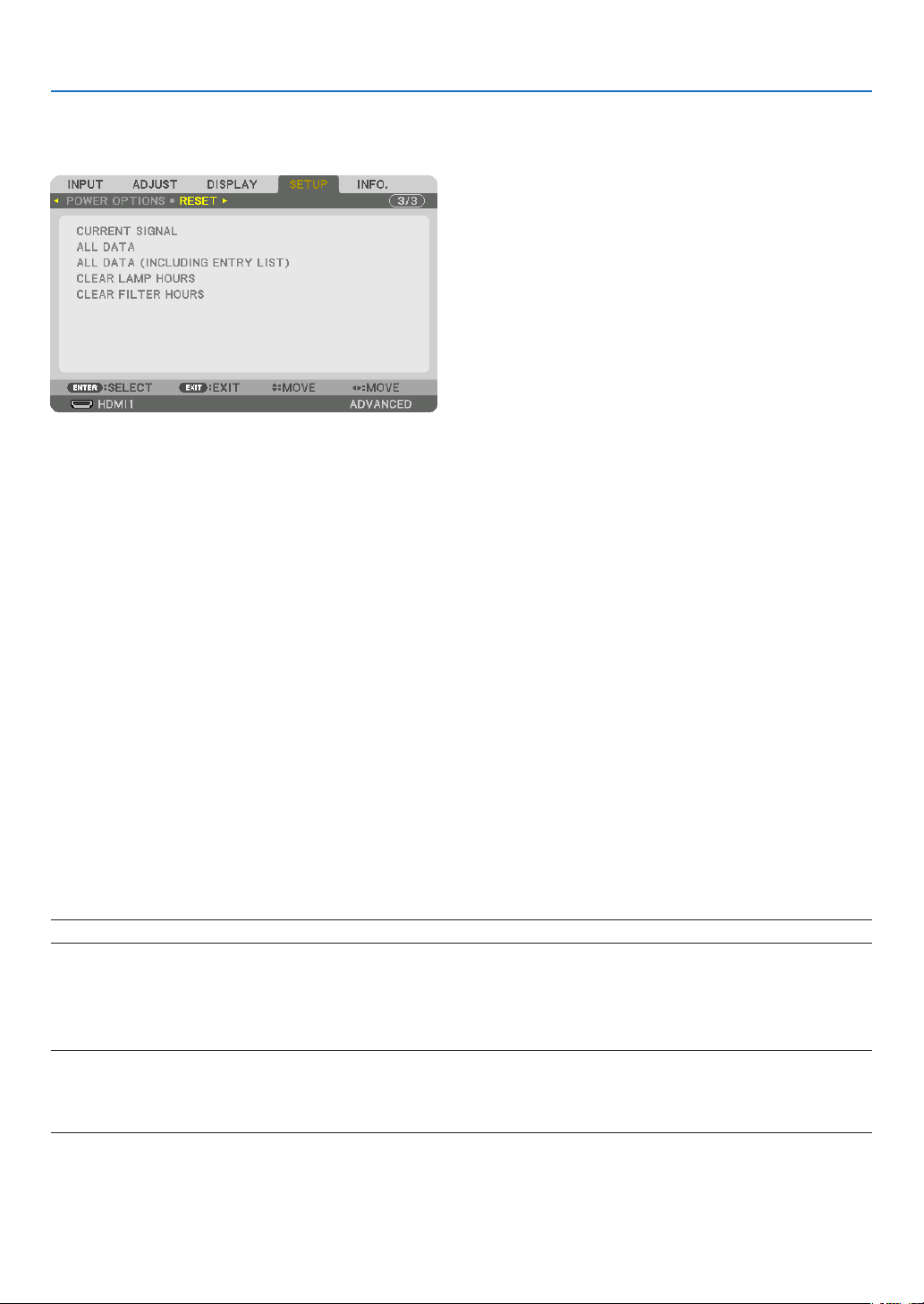
134
5. Using On-Screen Menu
Returning to Factory Default [RESET]
TheRESETfeatureallowsyoutochangeadjustmentsandsettingstothefactorypresetfora(all)source(s)except
thefollowing:
[CURRENT SIGNAL]
Resetstheadjustmentsforthecurrentsignaltothefactorypresetlevels.
Theitemsthatcanberesetare:[PRESET],[CONTRAST],[BRIGHTNESS],[COLOR],[HUE],[SHARPNESS],[AS-
PECTRATIO],[HORIZONTAL],[VERTICAL],[CLOCK],[PHASE],and[OVERSCAN].
[ALL DATA]
Resetalltheadjustmentsandsettingsforallthesignalstothefactorypreset.
All items can be reset EXCEPT [ENTRY LIST], [LANGUAGE], [BACKGROUND], [FILTER MESSAGE], [EDGE
BLENDING],[MULTISCREEN],[SCREENTYPE],[GEOMETRICCORRECTION],[REF.WHITEBALANCE],[STATIC
CONVERGENCE],[REF.LENSMEMORY],[ADMINISTRATORMODE],[CONTROLPANELLOCK],[SECURITY],
[COMMUNICATIONSPEED],[DATEANDTIMESETTINGS],[CONTROLID],[STANDBYMODE],[FANMODE],
[EDIDVERSION],[HDCPVERSION],[LAMPLIFEREMAINING],[LAMPHOURSUSED],[FILTERHOURSUSED],
[TOTALCARBONSAVINGS],[WIREDLAN].
Toresetthelampusagetime,see“ClearingLampHourMeter[CLEARLAMPHOURS]”below.
[ALLDATA(INCLUDINGENTRYLIST)]
Resetalltheadjustmentsandsettingsforallthesignalsincludingthe[ENTRYLIST]tothefactorypresetexcept
[LANGUAGE],[BACKGROUND],[FILTERMESSAGE],[EDGEBLENDING],[MULTISCREEN],[SCREENTYPE],
[GEOMETRIC CORRECTION], [REF. WHITE BALANCE], [STATIC CONVERGENCE], [REF. LENS MEMORY],
[ADMINISTRATORMODE], [CONTROLPANELLOCK],[SECURITY],[COMMUNICATIONSPEED],[DATEAND
TIMESETTINGS],[CONTROLID],[STANDBYMODE],[FANMODE],[EDIDVERSION],[HDCPVERSION],[LAMP
LIFEREMAINING],[LAMPHOURSUSED],[FILTERHOURSUSED],[TOTALCARBONSAVINGS],[WIREDLAN].
Alsodeletesallthesignalsinthe[ENTRYLIST]andreturnstothefactorypreset.
NOTE:LockedsignalsinEntryListcannotbereset.
Clearing Lamp Hour Meter [CLEAR LAMP HOURS]
Resetsthelamp clockbacktozero.Selectingthisoptiondisplayssubmenufora conrmation.Select[YES]and
presstheENTERbutton.
NOTE:
• Elapsedtimeofthelampusewillnotbeaffectedevenwhen[RESET]isdonefromthemenu.
• Performing[CLEARLAMPHOURS]willreturnthe[REF.LIGHT]in[LIGHTMODE]toitsdefaultadjustments.Whentheprojector
isusedformulti-screenprojection,use[REF.LIGHT]toadjustthebrightnessagain.

135
5. Using On-Screen Menu
Clearing the Filter Usage Hours [CLEAR FILTER HOURS]
Resetsthelterusagebacktozero.Selectingthisoptiondisplayssubmenuforaconrmation.Select[YES]and
presstheENTERbutton.
The[OFF]itemisselectedfor[FILTERMESSAGE]atthetimeofshipment.When[OFF]isselected,youdonotneed
toclearthelterusagehour.
NOTE:Elapsedtimeofthelterusewillnotbeaffectedevenwhen[RESET]isdonefromthemenu.
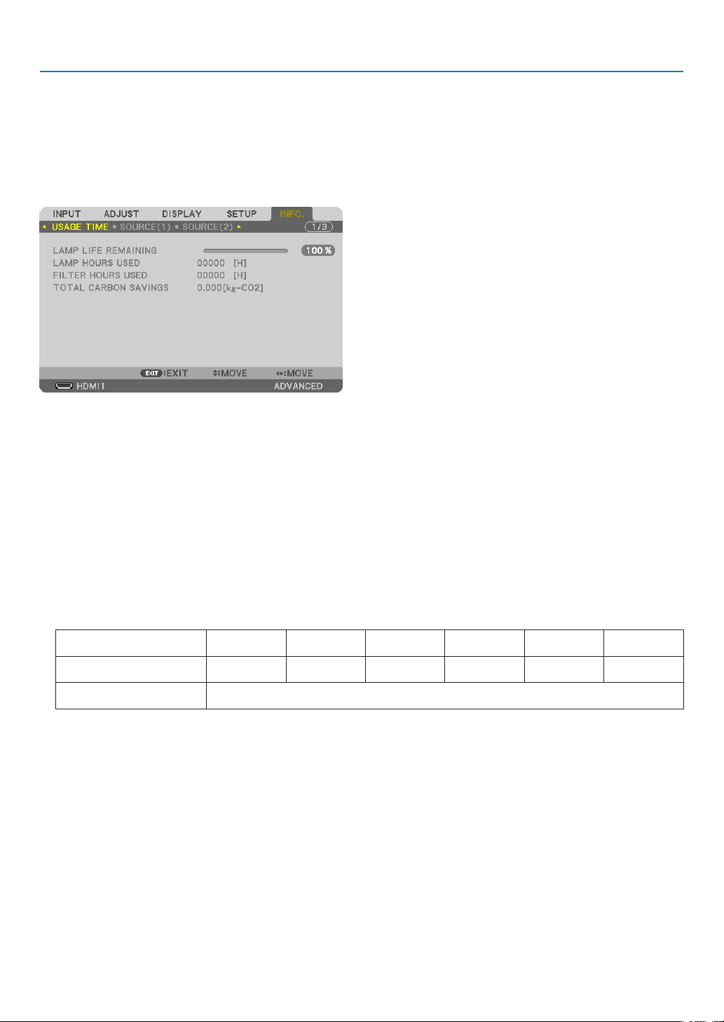
136
5. Using On-Screen Menu
❽ Menu Descriptions & Functions [INFO.]
Displaysthestatusofthecurrentsignalandlampusage.Thisitemhasninepages.Theinformationincludedisas
follows:
TIP:PressingtheHELPbuttonontheremotecontrolwillshowthe[INFO.]menuitems.
[USAGE TIME]
[LAMPLIFEREMAINING](%)*
[LAMPHOURSUSED](H)
[FILTERHOURSUSED](H)
[TOTALCARBONSAVINGS](kg-CO2)
* Theprogressindicatorshowsthepercentageofremainingbulblife.
Thevalueinformsyouoftheamountoflampusage.Whentheremaininglamptimereaches0,theLAMPLIFE
REMAININGbarindicatorchangesfrom0%to100Hoursandstartscountingdown.
• Themessagetotheeffectthatthelamportheltersshouldbereplacedwillbedisplayedforoneminutewhenthe
projectoristurnedonandwhenthePOWERbuttonontheprojectorortheremotecontrolispressed.
Todismissthismessage,pressanybuttonontheprojectorortheremotecontrol.
NP42LPLamplife(H) PA803U PA723U PA653U PA853W PA703W PA903W
ECOmodeOFF 3000 3500 4000 3000 4000 3000
ECOmode 5000
• [TOTALCARBONSAVINGS]
Thisdisplaystheestimatedcarbonsavinginformationinkg.Thecarbonfootprintfactorinthecarbonsavingcal-
culationisbasedontheOECD(2008Edition).(→page37)
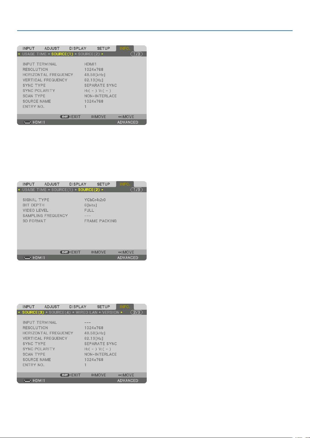
137
5. Using On-Screen Menu
[SOURCE(1)]
INPUTTERMINAL RESOLUTION
HORIZONTALFREQUENCY VERTICAL FREQUENCY
SYNCTYPE SYNC POLARITY
SCANTYPE SOURCE NAME
ENTRYNO.
[SOURCE(2)]
SIGNALTYPE BITDEPTH
VIDEOLEVEL SAMPLING FREQUENCY
3DFORMAT
[SOURCE(3)]
INPUTTERMINAL RESOLUTION
HORIZONTALFREQUENCY VERTICAL FREQUENCY
SYNCTYPE SYNC POLARITY
SCANTYPE SOURCE NAME
ENTRYNO.
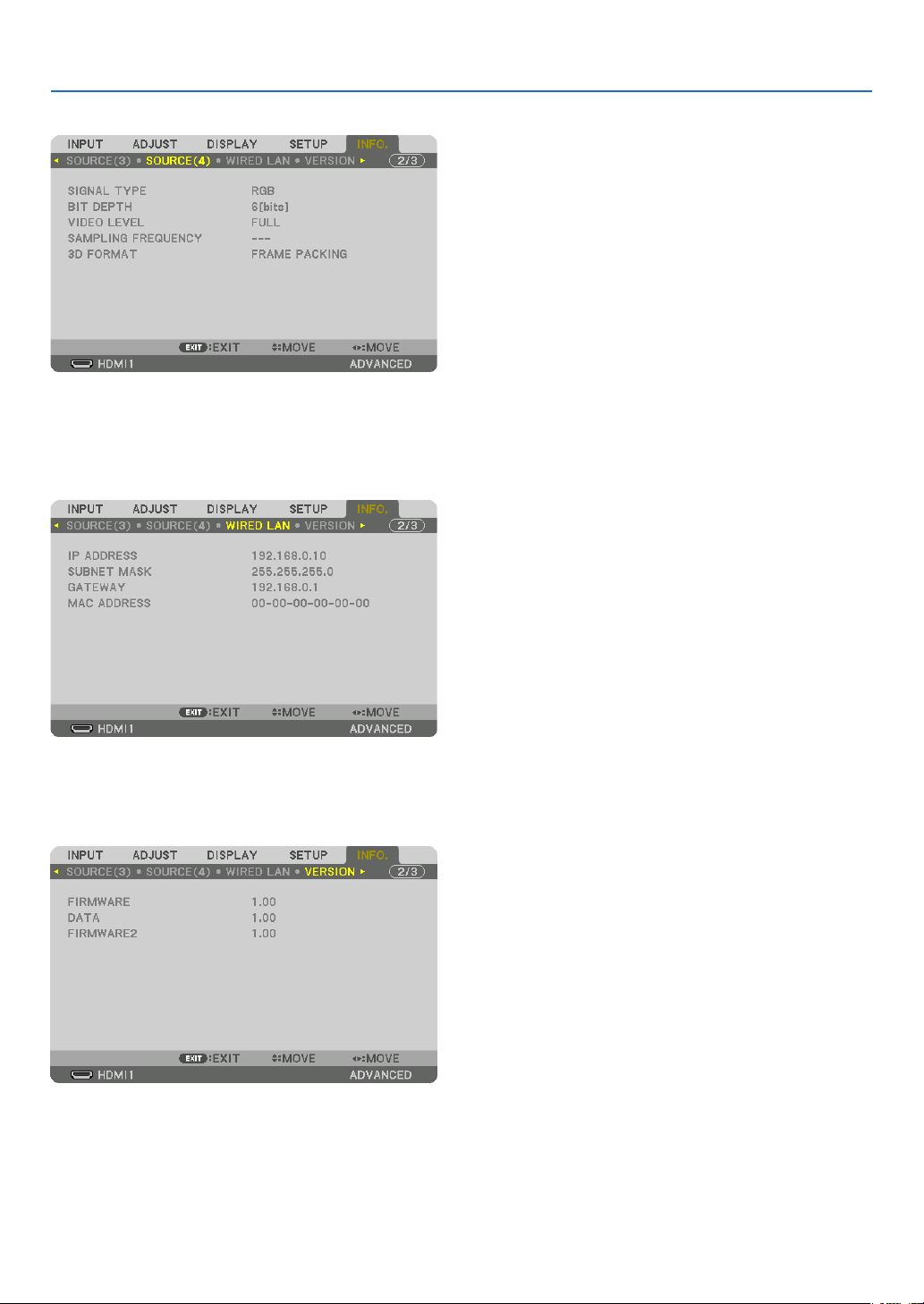
138
5. Using On-Screen Menu
[SOURCE(4)]
SIGNALTYPE BITDEPTH
VIDEOLEVEL SAMPLING FREQUENCY
3DFORMAT
[WIRED LAN]
IPADDRESS SUBNETMASK
GATEWAY MACADDRESS
[VERSION]
FIRMWARE DATA
FIRMWARE2
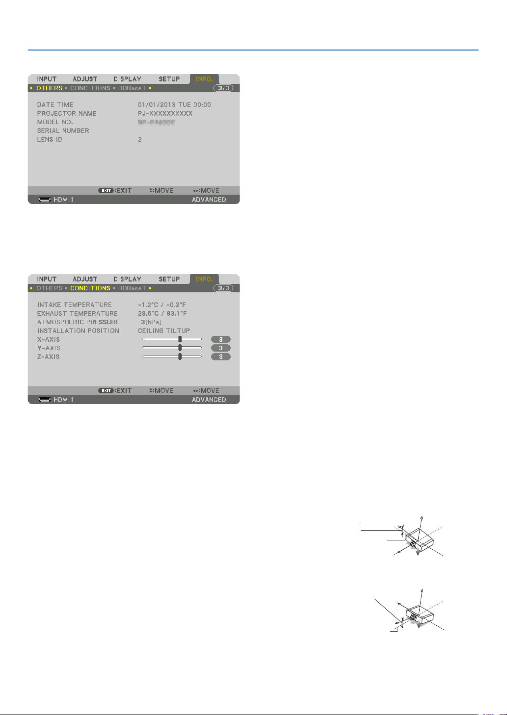
139
5. Using On-Screen Menu
[OTHERS]
DATETIME PROJECTORNAME
MODELNO. SERIAL NUMBER
LENSID
[CONDITIONS]
INTAKETEMPERATURE EXHAUSTTEMPERATURE
ATMOSPHERICPRESSURE INSTALLATIONPOSITION
X-AXIS Y-AXIS
Z-AXIS
AbouttheX-AXIS,Y-AXISandZ-AXISCONDITIONS
* ArrowdirectionoftheZ-AXISinthegurerepresentsthetopoftheprojector.
X-AXIS ������������������� Display the projector image at an angle of −100 – +100
degrees to the horizontal in the X-axis direction�
X-AXIS value of
the projector
Horizontal plane
X-axis
Gravity direction
Y-AXIS ������������������� Display the projector image at an angle of −100 – +100
degrees to the horizontal in the Y-axis direction�
Y-AXIS value of
the projector
Horizontal plane
Y-axis
Gravity direction
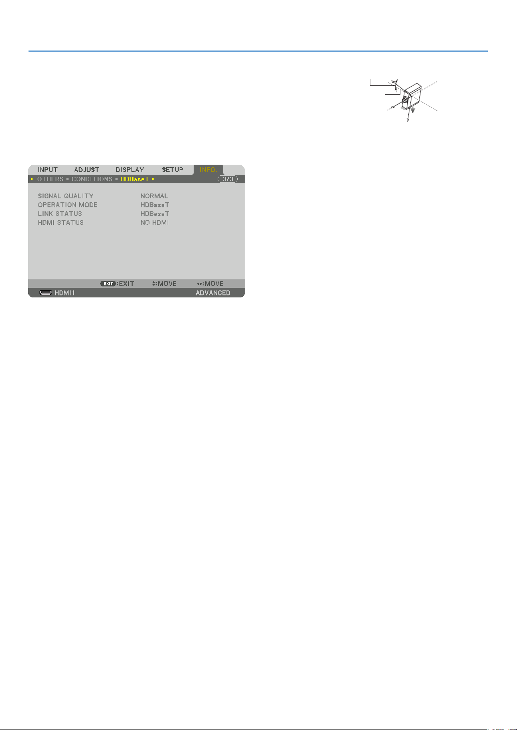
140
5. Using On-Screen Menu
Z-AXIS ������������������� Display the projector image at an angle of −100 – +100
degrees to the vertical in the Z-axis direction�
Z-AXIS value of
the projector
Horizontal
plane Z-axis
Gravity direction
[HDBaseT]
SIGNALQUALITY OPERATIONMODE
LINKSTATUS HDMISTATUS
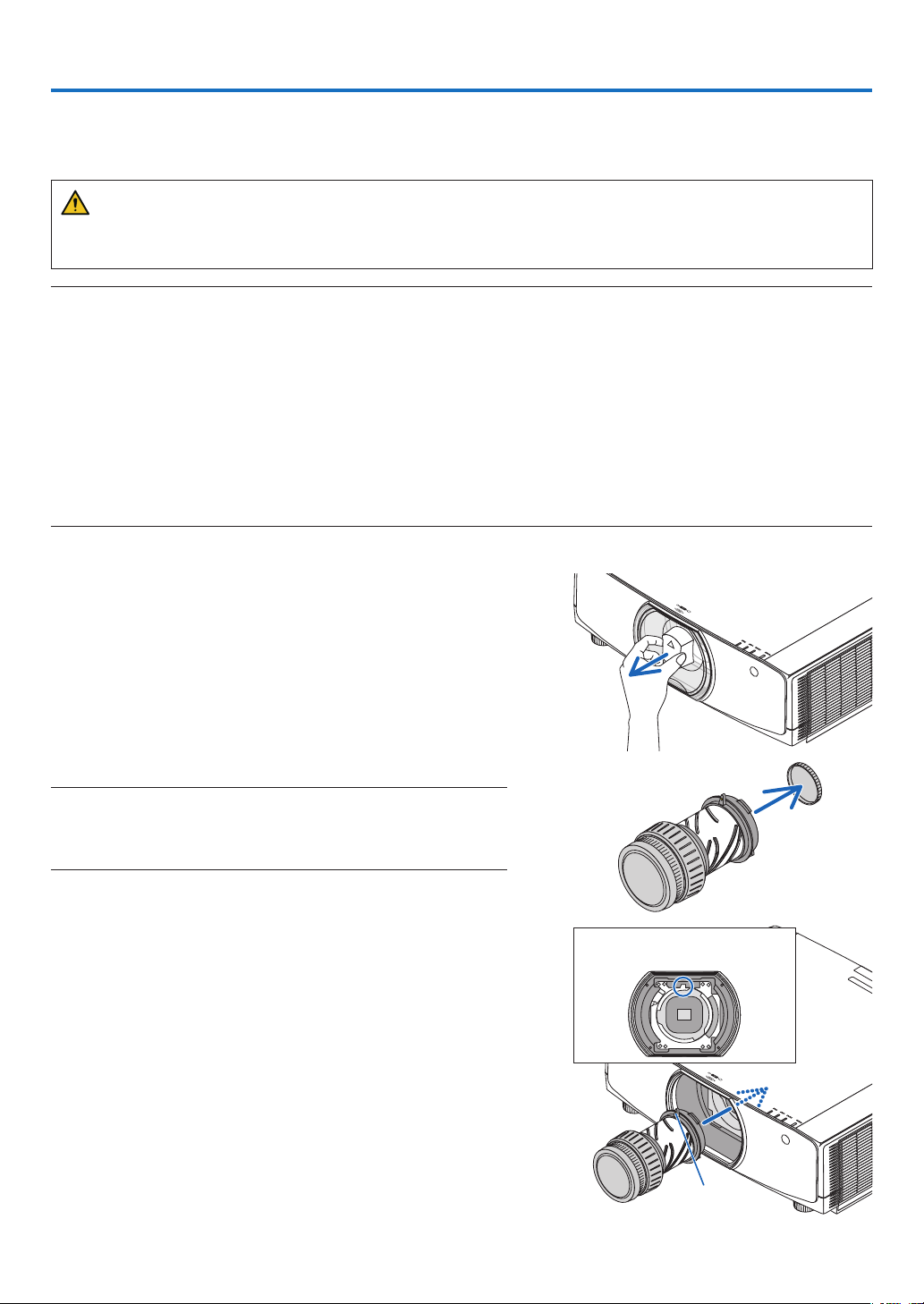
141
❶ Mounting a lens (sold separately)
Eightseparatebayonetstylelensescanbeusedwiththisprojector.ThedescriptionsherearefortheNP13ZL(2x
zoom)lens.Mountotherlensesinthesamemanner.
WARNING:
(1)Turnoffthepowerandwaitforthecoolingfantostop,(2)disconnectthepowercordandwaitfortheunitto
coolbeforemountingorremovingthelens.Failuretodosocanresultineyeinjury,electricshock,orburninjuries.
Important:
• Besuretocarryout[LENSCALIBRATION]afterreplacingthelens.
• Theprojectorandlensesaremadeofprecisionparts.Donotsubjectthemtoshockorexcessiveforces.
• Removetheseparatelysoldlenswhenmovingtheprojector.Ifnot,thelenscouldbesubjecttoshockwhiletheprojectorisbeing
moved, damaging the lens and the lens shift mechanism.
• Whendismountingthelensfromtheprojector,returnthelenspositiontothehomepositionbeforeturningoffthepower.Failure
to do so may prevent the lens from being mounted or dismounted because of narrow space between the projector and the lens.
• Nevertouchthelenssurfacewhiletheprojectorisoperating.
• Beverycarefulnottoletdirt,grease,etc.,onthelenssurfaceandnottoscratchthelenssurface.
• Performtheseoperationsonaatsurfaceoverapieceofcloth,etc.,topreventthelensfromgettingscratched.
• Whenleavingthelensofftheprojectorforlongperiodsoftime,mountthedustcapontheprojectortopreventdustordirtfrom
getting inside.
Mounting the lens
1. Removethedustcapfromtheprojector.
2. Removethelenscaponthebackofthelens.
NOTE:
• Makesuretoremovethelenscapattheunitbackside.Ifthelensunit
with the lens cap remaining on is installed on the projector, it may cause
of malfunction.
3. Aligntheprotrusiononthelenswiththeguidingnotchon
the projector lens hole and insert the lens.
NP11FL/NP30ZL/NP12ZL/NP13ZL/NP14ZL
Each protrusion is marked in yellow.
NP40ZL/NP41ZL/NP43ZL
The arrow mark in the label attached to the lens shows the
position of protrusion.
Insert the lens slowly all the way in.
Guiding notch
Protrusion
6. Connecting to Other Equipment
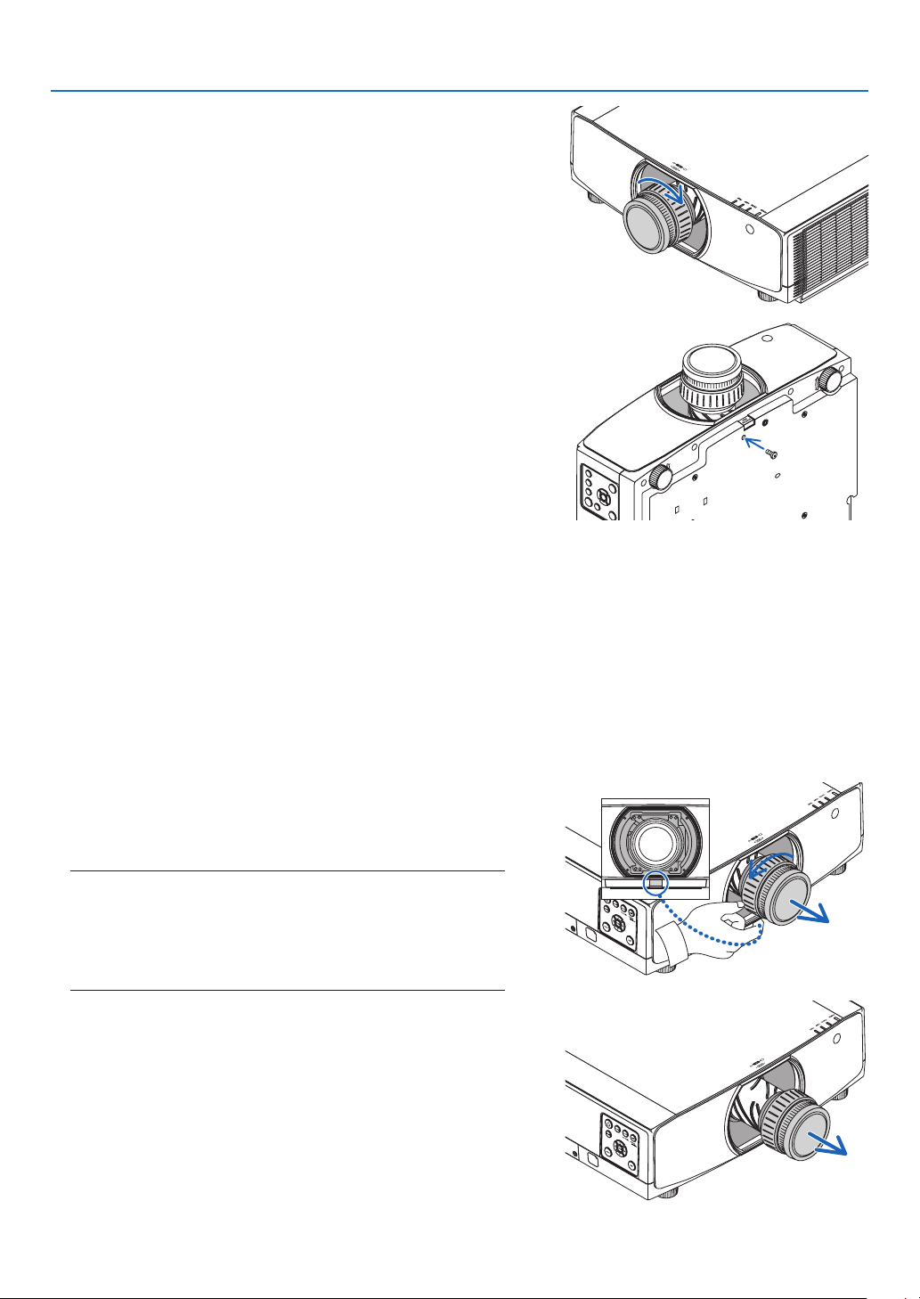
142
6. Connecting to Other Equipment
4. Turnthelensclockwise.
Turn until a click is heard.
The lens is now fastened onto the projector.
TIP:Mountingthelenstheftpreventionscrew
Fastenthelenstheftpreventionscrewincludedwiththeprojectortothe
bottom of the projector so that the lens cannot be removed easily.
Removing the lens
Preparations:
1. Turn on the projector and display an image.
2. Press and hold the SHIFT/HOME POSITION button over 2 seconds.
The lens position will be moved to the home position.
3. Turn off the main power switch, and then unplug the power cord.
4. Wait until the projector cabinet is cool enough to handle.
Ifthelenstheftpreventionscrewhasbeenseton,removeitrst.
1. While pressing the lens release button at the bottom of
lensmountingsectionontheprojector’sfrontpanelfully
in,turnthelenscounterclockwise.
The lens comes off.
NOTE:
• Checkthefollowingareasifthelensunitcannotberemovedeven
when the lens release button is pressed.
1. The lens release button may be locked sometimes. In that case,
turn the lens fully to the right. The lens release button lock will
be released.
2. Slowly pull the lens off the projector.
• After removing the lens, mount the lens caps (front and
back) included with the lens before storing the lens.
• Ifnolensisgoingtobemountedontheprojector,mount
the dust cap included with the projector.
Make sure the direction to mount the dust cap to face the
distinguish mark (△) on the cap upward.
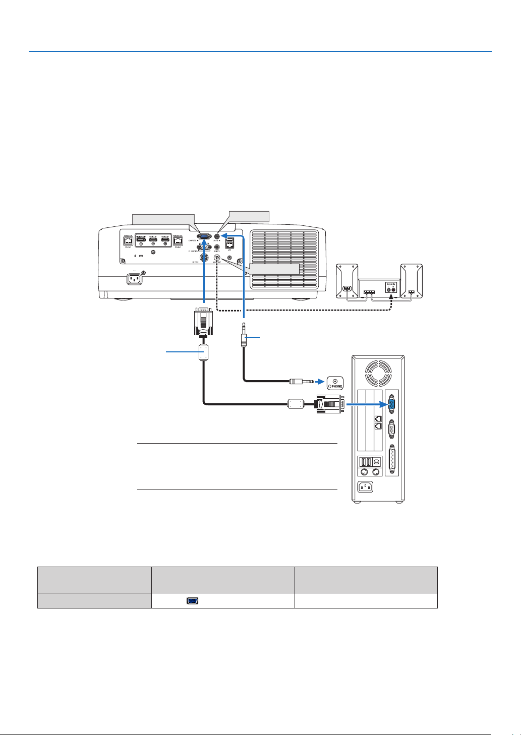
143
6. Connecting to Other Equipment
❷ Making Connections
Acomputercable,HDMIcable,oraDisplayPortcablecanbeusedtoconnecttoacomputer.
Theconnectioncableisnotenclosedwiththeprojector.Pleasegetreadyasuitablecablefortheconnection.
Analog RGB signal connection
• Connectthecomputercabletothemonitoroutterminal(miniD-sub15pin)onthecomputerandthecomputer
video input terminal on the projector. Please use a computer cable attached with a ferrite core.
• Selectthesourcenameforitsappropriateinputconnectorafterturningontheprojector.
Inputconnector
INPUTbuttonontheprojector
cabinet
Buttonontheremotecontrol
COMPUTERIN
4:COMPUTER
4/COMPUTER
COMPUTER IN
AUDIO IN
AUDIO OUT
Stereo mini-plug audio cable (not supplied)
NOTE:
• Pleasechecktheoperatingmanualofthecomputeras
the name, position and direction of the terminal may
differ depending on the computer.
Computer cable (sold commercially)
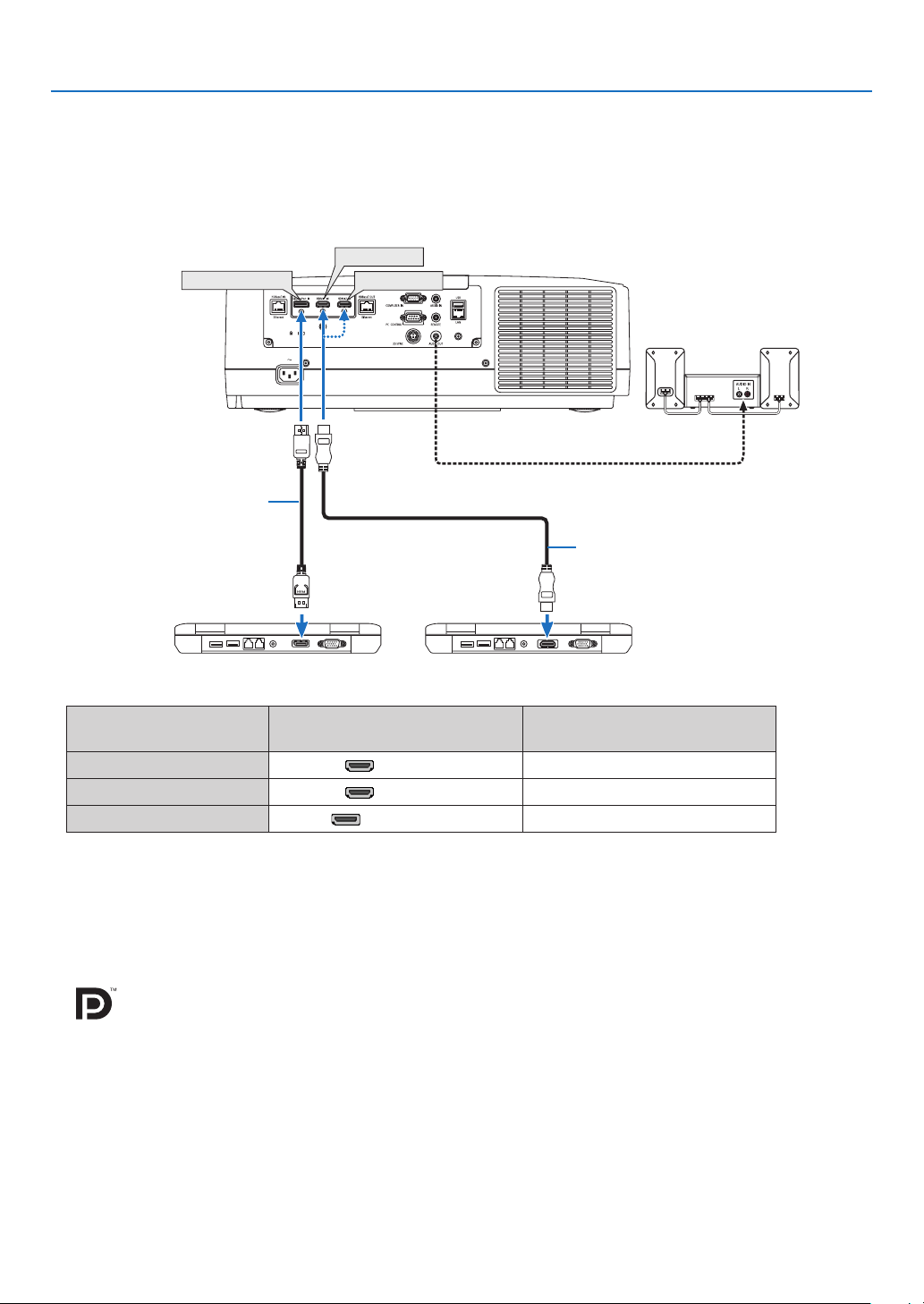
144
6. Connecting to Other Equipment
Digital RGB signal connection
• ConnectacommerciallyavailableHDMIcablebetweenthecomputer’sHDMIoutputconnectorandtheprojector’s
HDMI1orHDMI2inputconnector.
• ConnectacommerciallyavailableDisplayPortcablebetweenthecomputer’sDisplayPortoutputconnectorand
theprojector’sDisplayPortinputconnector.
• Selectthesourcenameforitsappropriateinputconnectorafterturningontheprojector.
Inputconnector
INPUTbuttonontheprojector
cabinet
Buttonontheremotecontrol
HDMI1IN 1:HDMI1 1/HDMI1
HDMI2IN 2:HDMI2 2/HDMI2
DisplayPortIN
3:DisplayPort
3/DisplayPort
Cautions when connecting an HDMI cable
• UseacertiedHighSpeedHDMI
®
CableorHighSpeedHDMI
®
CablewithEthernet.
Cautions when connecting a DisplayPort cable
• UseacertiedDisplayPortcable.
• Dependingonthecomputer,sometimemayberequireduntiltheimageisdisplayed.
• SomeDisplayPortcables(commerciallyavailable)havelocks.
• Todisconnectthecable,pressthebuttononthetopofthecable’sconnector,thenpullthecableout.
• PowercanbesuppliedtotheconnectingdevicefromtheDisplayPortinputterminal(maximumof1.65W).However,
power will not be supplied to the computer.
• WhensignalsfromadevicethatusesasignalconverteradapterareconnectedtotheDisplayPortinputconnector,
insomecasestheimagemaynotbedisplayed.
• WhentheHDMIoutputofacomputerisconnectedtotheDisplayPortinputconnector,useaconverter(commer-
ciallyavailable).
HDMI 1 IN
HDMI 2 IN
DisplayPort IN
HDMI cable (not supplied)
DisplayPort cable (not supplied)
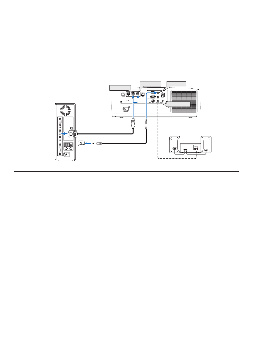
145
6. Connecting to Other Equipment
CautionswhenusingaDVIsignal
• Whenthe computerhasa DVI output connector,useacommerciallyavailableconvertercabletoconnectthe
computertotheprojector’sHDMI1orHDMI2inputconnector(onlydigitalvideosignalscanbeinput).Also,con-
nectthecomputer’saudiooutputtotheprojector’saudioinputconnector.Inthiscase,switchtheHDMI1orHDMI2
settingaton-screenmenu’saudioselectionontheprojectorto[COMPUTER].(→page130)
Toconnectthecomputer’sDVIoutputconnectortotheprojector’sDisplayPortinputconnector,useacommercially
available converter.
HDMI 1 IN
HDMI 2 IN
AUDIO IN
AUDIO OUT
NOTE:WhenViewingaDVIDigitalSignal
• Turnoffthepowerofthecomputerandprojectorbeforeconnecting.
• Lowerthecomputer’svolumesettingbeforeconnectinganaudiocabletotheheadphonesconnector.Whenusingwithacomputer
connected to the projector, adjust the volume of both the projector and computer to set the appropriate volume level.
• Ifthecomputerhasamini-jacktypeaudiooutputconnector,werecommendconnectingtheaudiocabletothatconnector.
• Whenavideodeckisconnectedviaascanconverter,etc.,thedisplaymaynotbecorrectduringfast-forwardingandrewinding.
• UseaDVI-to-HDMIcablecompliantwithDDWG(DigitalDisplayWorkingGroup)DVI(DigitalVisualInterface)revision1.0stan-
dard.Thecableshouldbewithin197"/5mlong.
• TurnofftheprojectorandthePCbeforeconnectingtheDVI-to-HDMIcable.
• ToprojectaDVIdigitalsignal:Connectthecables,turntheprojectoron,thenselecttheHDMIinput.Finally,turnonyourPC.
Failuretodosomaynotactivatethedigitaloutputofthegraphicscardresultinginnopicturebeingdisplayed.Shouldthishappen,
restartyourPC.
• SomegraphicscardshavebothanalogRGB(15-pinD-Sub)andDVI(orDFP)outputs.Useofthe15-pinD-Subconnectormay
result in no picture being displayed from the digital output of the graphics card.
• DonotdisconnecttheDVI-to-HDMIcablewhiletheprojectorisrunning.Ifthesignalcablehasbeendisconnectedandthen
reconnected,animagemaynotbecorrectlydisplayed.Shouldthishappen,restartyourPC.
• TheCOMPUTERvideoinputconnectorssupportWindowsPlugandPlay.
• AMacsignaladapter(commerciallyavailable)mayberequiredtoconnectaMaccomputer.
ToconnectaMaccomputerequippedwithaMiniDisplayPorttotheprojector,useacommerciallyavailableMiniDisplayPort→
DisplayPortconvertercable.
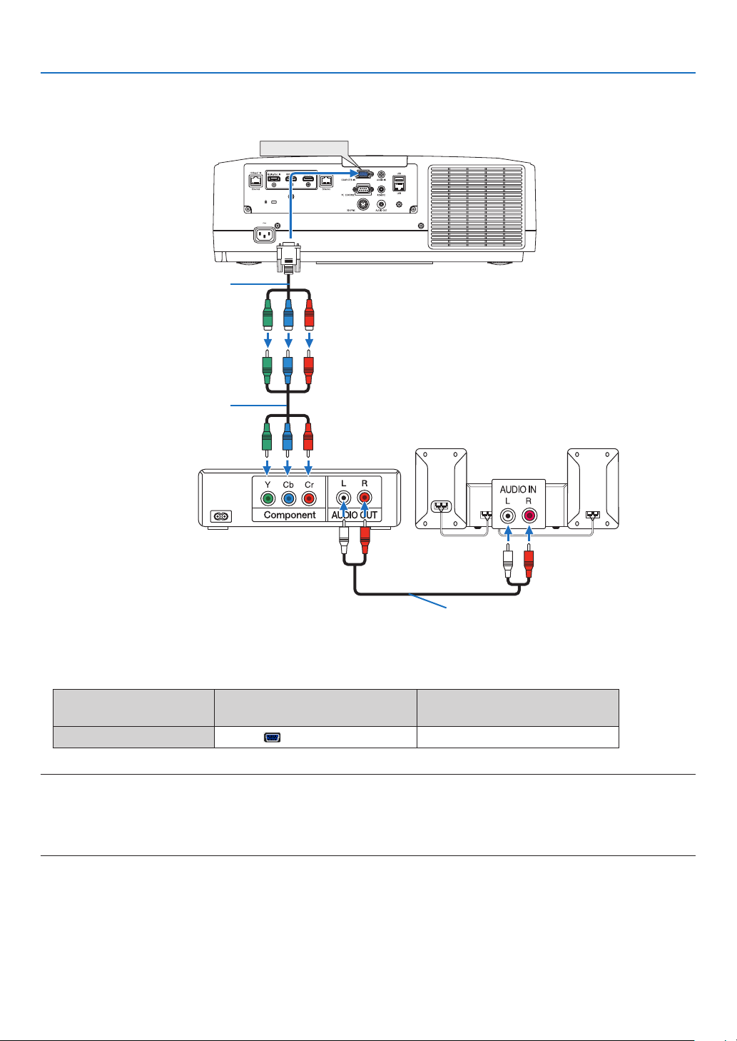
146
6. Connecting to Other Equipment
Connecting Component Input
• Selectthesourcenameforitsappropriateinputconnectorafterturningontheprojector.
Inputconnector
INPUTbuttonontheprojector
cabinet
Buttonontheremotecontrol
COMPUTERIN
4:COMPUTER
4/COMPUTER
NOTE:
• Whenthesignalformatissetto[AUTO](defaultfactorysettingwhenshipped),thecomputersignalandcomponentsignalare
automaticallydistinguished and switched. Ifthe signals cannotbe distinguished, select [COMPONENT] under [ADJUST] →
[VIDEO]→[SIGNALTYPE]intheon-screenmenuoftheprojector.
• ToconnecttoavideodevicewithaDconnector,usethesoldseparatelyDconnectorconverteradapter(modelADP-DT1E).
COMPUTER IN
15-pin - to - RCA (female) × 3 cable
adapter (ADP-CV1E)
Stereo mini plug - to - RCA audio cable (not
supplied)
Component video RCA × 3 cable
(not supplied)
Blu-ray player
Audio Equipment
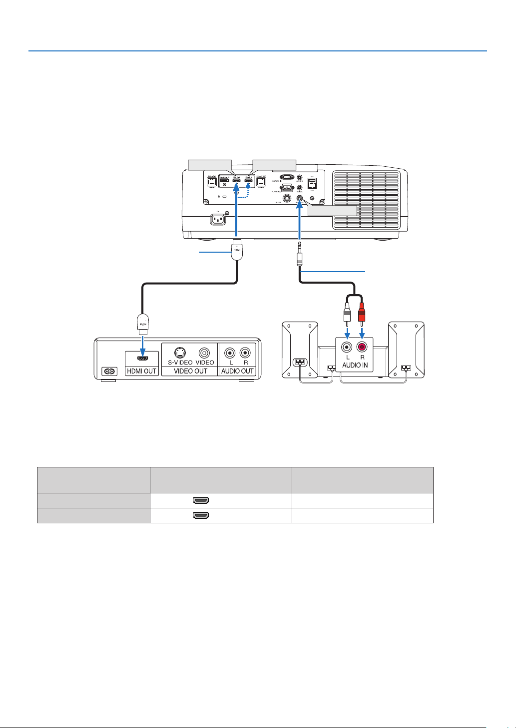
147
6. Connecting to Other Equipment
Connecting HDMI Input
YoucanconnecttheHDMIoutputofyourBlu-rayplayer,harddiskplayer,ornotebooktypePCtotheHDMI1INor
HDMI2INconnectorofyourprojector.
Inputconnector
INPUTbuttonontheprojector
cabinet
Buttonontheremotecontrol
HDMI1IN 1:HDMI1 1/HDMI1
HDMI2IN 2:HDMI2 2/HDMI2
TIP:ForusersofaudiovideoequipmentwithanHDMIconnector:
Select“Enhanced”ratherthan“Normal”ifHDMIoutputisswitchablebetween“Enhanced”and“Normal”.
This will provide improved image contrast and more detailed dark areas.
Formoreinformationonsettings,refertotheinstructionmanualoftheaudiovideoequipmenttobeconnected.
• WhenconnectingtheHDMI1INorHDMI2INconnectoroftheprojectortotheBlu-rayplayer,theprojector’svideo
levelcanbemadesettingsinaccordancewiththeBlu-rayplayer’svideolevel.Inthemenuselect[ADJUST]→
[VIDEO]→[VIDEOLEVEL]andmakenecessarysettings.
• IftheHDMIinput’ssoundisnotoutput,checkif[HDMI1]and[HDMI2]areset[HDMI1]and[HDMI2]correctlythe
on-screenmenu[SETUP]→[SOURCEOPTIONS]→[AUDIOSELECT].(→page130)
HDMI 1 IN
HDMI 2 IN
AUDIO OUT
Audio cable (not supplied)
HDMI cable (not supplied)
Use High Speed HDMI
®
Cable.
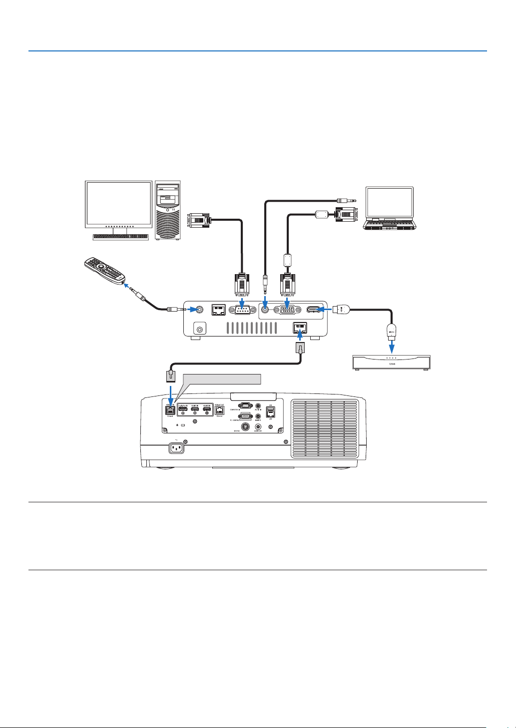
148
6. Connecting to Other Equipment
Connecting to a HDBaseT transmission device (sold commercially)
UseaLANcablesoldcommerciallytoconnecttheHDBaseTIN/Ethernetportoftheprojector(RJ-45)toaHDBaseT
transmission device sold commercially.
TheHDBaseTIN/EthernetportoftheprojectorsupportsHDMIsignals(HDCP)fromtransmissiondevices,control
signalsfromexternaldevices(serial,LAN)andremotecontrolsignals(IRcommands).
• Refertotheowner’smanualaccompaniedwithyourHDBaseTtransmissionforconnectingwithyourexternalde-
vices.
Connection example
RS-232CLAN
AUDIO IN HDMI IN
Wired-Remote
DC IN
HDBaseT
COMPUTER IN
HDBaseT IN/Ethernet
Computer (for control use)
Computer (for output use)
Example of a transmission device
Our company’s remote
control (RD-465E)
HDMI output video device
NOTE:
• Pleaseuseashieldedtwistedpair(STP)cableofCategory5eorhigherfortheLANcable(soldcommercially).
• ThemaximumtransmissiondistanceovertheLANcableis100m.(themaximumdistanceis70mfora4Ksignal)
• Pleasedonotuseothertransmissionequipmentbetweentheprojectorandtransmissionequipment.Thepicturequalitymaybe
degraded as a result.
• ThisprojectorisnotguaranteedtoworkwithallHDBaseTtransmissiondevicessoldcommercially.
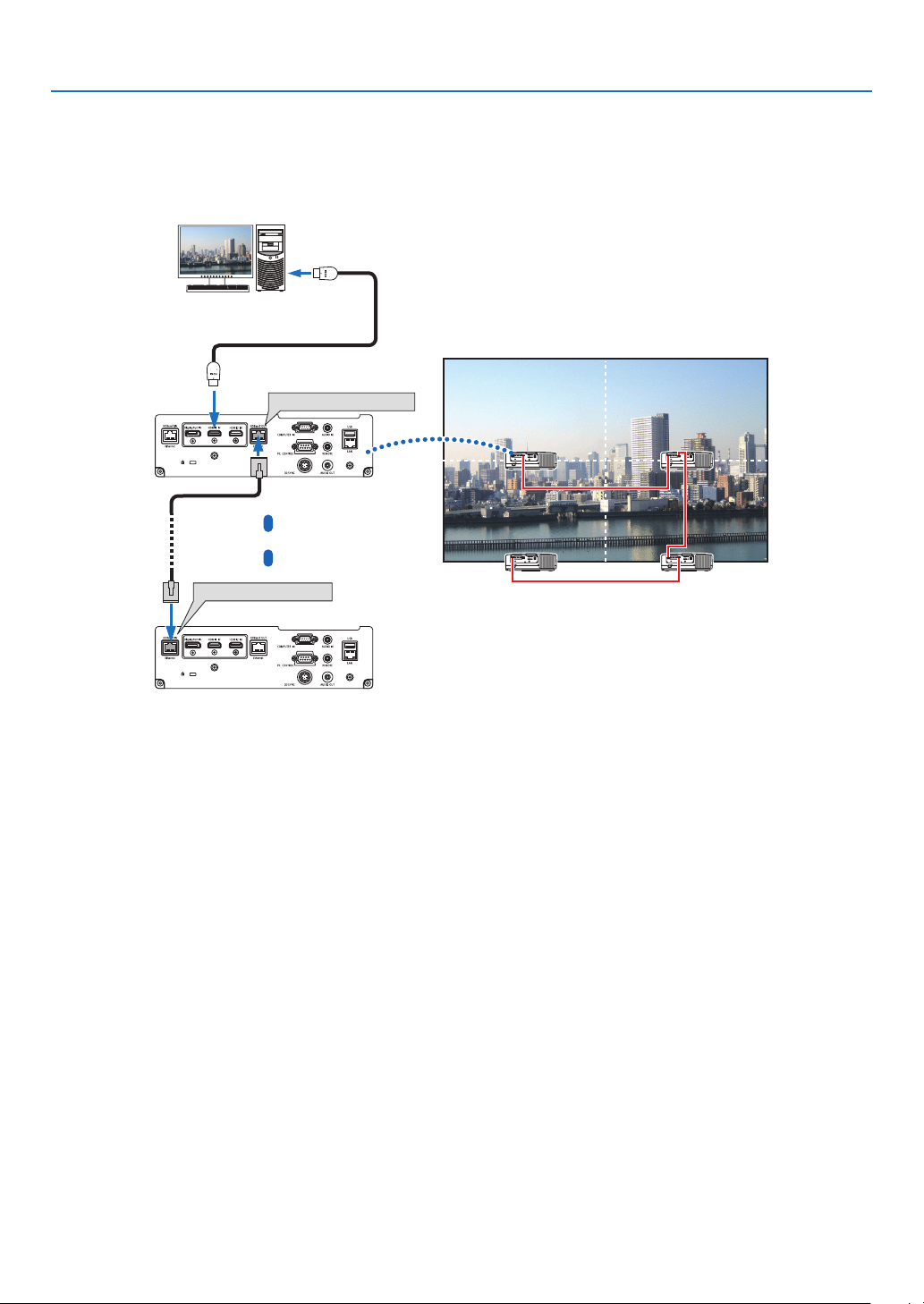
149
6. Connecting to Other Equipment
Connecting several projectors
ItenablestoprojectHDMI,DisplayPort,HDBaseTimageonseveralprojectorsconnectingtheHDBaseTIN/Ethernet
portandtheHDBaseTOUT/EthernetportbyLANcable.Theprojectorssupportsamebrightnessandresolutioncan
beconnecteduptofourunits,
HDBaseT OUT/Ethernet
HDBaseT IN/Ethernet
• ThesignalfromtheCOMPUTERINterminalisnotoutputfromtheHDBaseTOUT/Ethernetportofthisprojector.
• Projectorsofwhichbrightnessandresolutionaredifferent,thesecannotbeconnectedeveniftheseareinsame
series.Atthesametime,thisprojectorisnotguaranteedtoworkcorrectlyintheconnectionwithanotherdevice
as a monitor.
• WhenoutputtingHDMIsignals,turnonthepowerofthevideodeviceontheoutputsideandkeepitconnected
beforeinputtingvideosignalsintothisdevice.TheHDMIoutputterminalsoftheprojectorareequippedwithrepeater
functions.WhenadeviceisconnectedtotheHDMIoutputterminal,theresolutionoftheoutputsignalislimitedby
the resolution supported by the connected device.
• ConnectinganddisconnectinganHDMIcableorselectinganotherinputsourceonthesecondandsubsequent
projectorswilldisabletheHDMIrepeaterfunction.
Master projector
Other projector
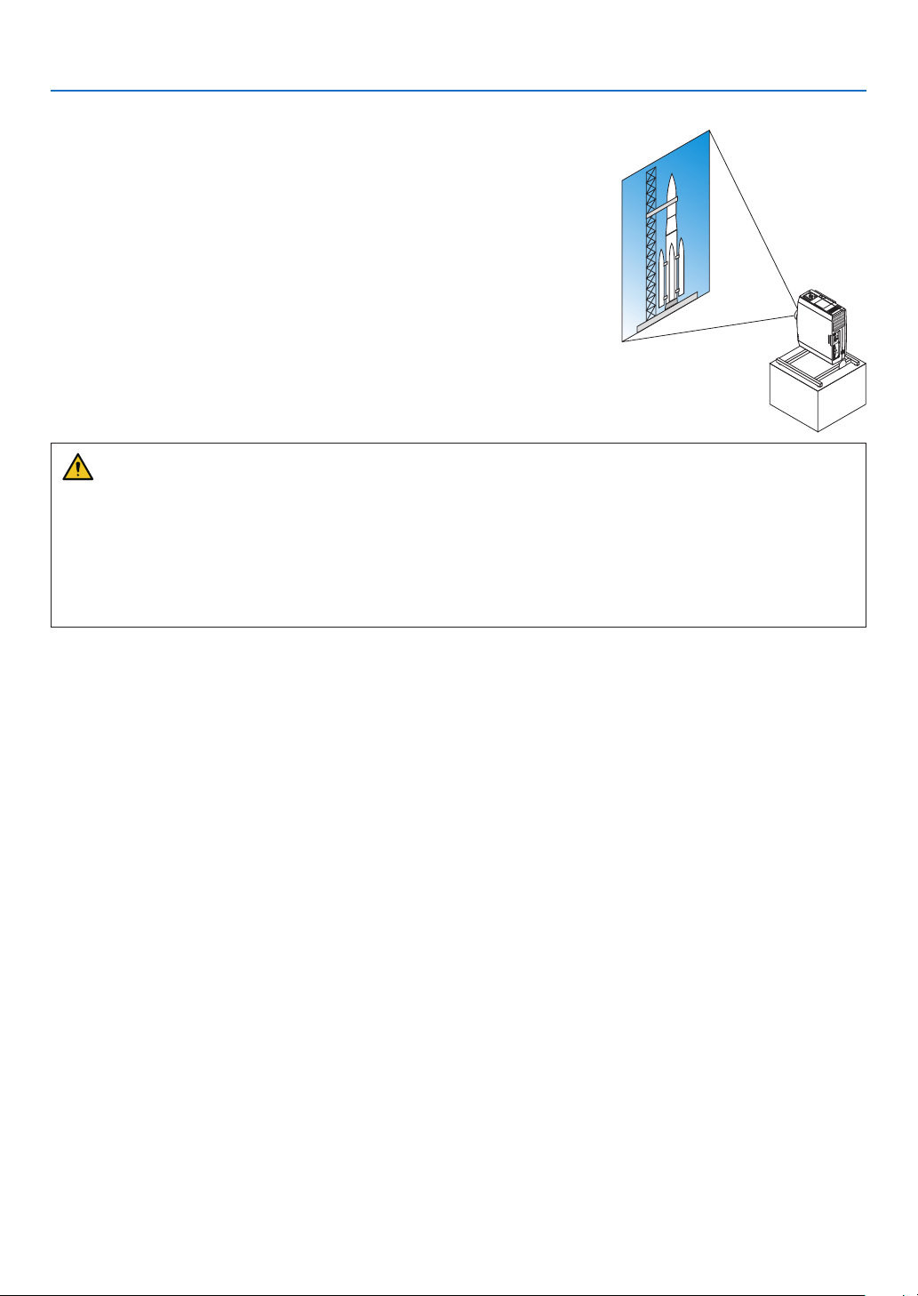
150
6. Connecting to Other Equipment
Portrait projection (vertical orientation)
Portraitscreensfromacomputercanbeprojectedbyinstallingtheprojec-
torinaverticalorientation.Angletodisplayallthescreenssuchasthe
on-screenmenucanbechangedbythemenu[SETUP]→[MENU(2)]
→[MENUANGLE].
Precautions during installation
• Pleasedonotinstalltheprojectorinaverticalorientationontopoftheoorortableonitsown.Theintakevent
maybeobstructed,resultingintheprojectorgettingwarmandthepossibilityofreandmalfunctionoccurring.
• Forverticalinstallation,installtheprojectorwiththeintakevent(lter)facingdownwards.Astandforsupporting
theprojectorneedstobemadeforthispurpose.Inthiscase,thestandmustbedesignedsuchthatthecenter
ofgravityoftheprojectorislocatedwellwithinthelegsofthestand.Ifnot,theprojectormayfalloverandresult
ininjury,damageandmalfunction.
Design and manufacturing conditions for the stand
Pleaseengageaninstallationserviceproviderforthedesignandmanufactureofthecustomizedstandtobeusedfor
portraitprojection.Pleaseensurethatthefollowingarecompliedwithwhendesigningthestand.
1. Maintainanopeningofatleast315×150mmsoasnottoobstructtheintakevent/lteroftheprojector.
2. Maintainadistanceofatleast130mmbetweentheprojectorintakeventandtheoor(fortheopeningofthelter
cover).
3. Usethefourscrewholesatthebackoftheprojectortosecureittothestand.
Screwholecenterdimension:200×250mm
Screwholedimensionontheprojector:M4withamaximumdepthof8mm.
* Pleasedesignthestandsuchthattherearlegsatthebackoftheprojectordonotcontactthestand.Thefront
legscanbeturnedandremoved.
4. Horizontaladjustmentmechanism(forexample,boltsandnutsinfourlocations)
5. Pleasedesignthestandsuchthatitdoesnottoppleovereasily.
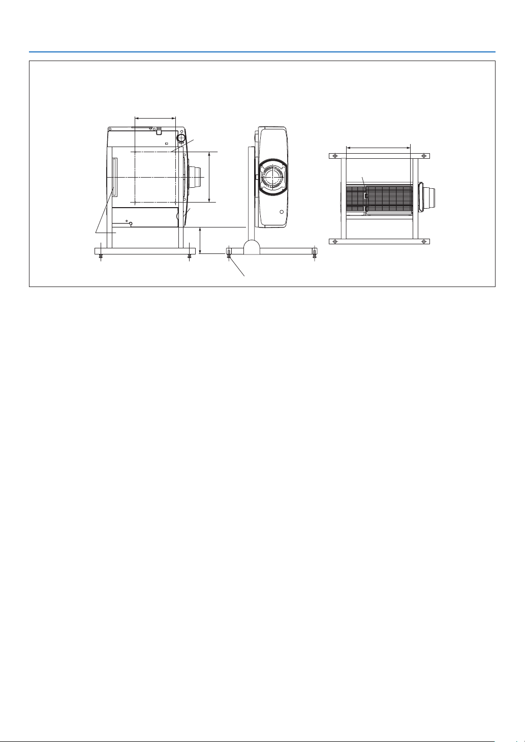
151
6. Connecting to Other Equipment
Reference drawings
* Thedrawingshowingthedimensionalrequirementsisnotanactualstanddesigndrawing.
[Side View] [Front View]
Screw holes for 4 -
M4 use
Tilt foot (remove)
130 or greater
200
Filter cover (when opened)
Horizontal adjuster
[Bottom View]
Filter cover
315 or greater
Rear foot
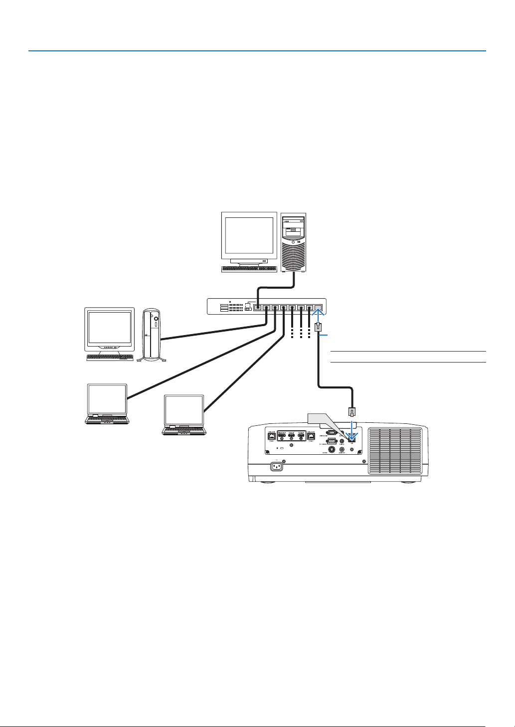
152
6. Connecting to Other Equipment
Connecting to a Wired LAN
TheprojectorcomesstandardwithaLANport(RJ-45)whichprovidesaLANconnectionusingaLANcable.
TouseaLANconnection,youarerequiredtosettheLANontheprojectormenu.Select[SETUP]→[NETWORK
SETTINGS]→[WIREDLAN].(→page126).
Example of LAN connection
ExampleofwiredLANconnection
LAN
Server
Hub
LAN cable (not supplied)
NOTE:UseaCategory5orhigherLANcable.

153
7. Maintenance
Thissectiondescribesthesimplemaintenanceproceduresyoushouldfollowtocleanthelters,thelens,thecabinet,
andtoreplacethelampandthelters.
❶ Cleaning the Filters
Thelterattheintakeventkeepsdustanddirtfromgettinginsidetheprojector.Ifthelterisdirtyorclogged,your
projector may overheat.
WARNING
• Pleasedonotuseaspraycontainingammablegastoremovedustattachedtothelters,etc.Doingsomay
resultinres.
NOTE:Themessageforltercleaningwillbedisplayedforoneminuteaftertheprojectoristurnedonoroff.Whenthemessageis
displayed,cleanthelters.Thetimetocleantheltersissetto[OFF]attimeofshipment.(→ page 112)
To cancel the message, press any button on the projector cabinet or the remote control.
Tocleanthelter,detachthelterunitandtheltercover.
CAUTION
• Beforecleaningthelters,turnofftheprojector,disconnectthepowercordandthenallowthecabinettocool.
Failuretodosocanresultinelectricshockorburninjuries.
1. Press down two buttons and then pull the filter cover
towards you to open it.
Filter cover Button
2. Pickthecenterofthefilterunitforpullingitout.
Filter unit
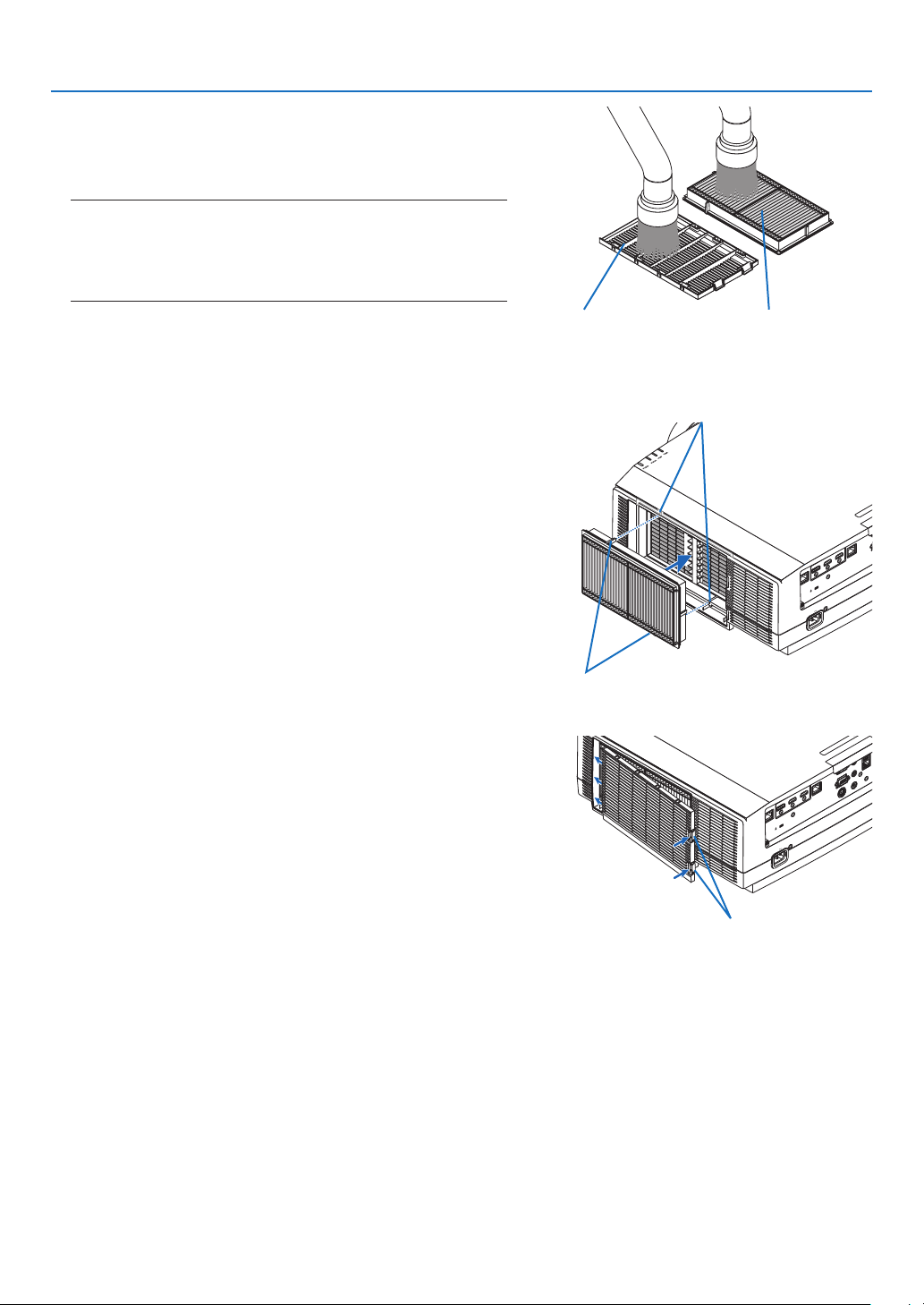
154
7. Maintenance
3. Vacuumdustonthefrontandbackfacesofthefilterunit.
• Getridofdustinthefilter.
• Gentlygetridofdustonthefiltercoverandintheaccordion
pleats of the filter.
NOTE:
• Wheneveryouvacuumthelter,usethesoftbrushattachmentto
vacuum. This is to avoid damage to the filter.
• Donotwashthelterwithwater.Doingsocanresultinlterclog-
ging.
Filter unitFilter cover
4. Mountthefilterunitbackontotheprojectorcabinet.
Insert the filter unit onto the projector aligning the two protru-
sions on each top and bottom of the filter unit to the grooves
on the projector cabinet.
Protrusion
Groove
5. Closethefiltercover.
Keep to push the filter cover frame around the buttons until
a “click” sound is heard. The filter cover will be secured in
position.
Button
6. Clearthefilterusagehours.
Plug the power cord into the wall outlet, and then turn on the
projector.
From the menu, select [RESET] → [CLEAR FILTER HOURS].
(→ page 135)
The interval time to clean the filters is set to [OFF] at time of
shipment. When using the projector as it is, you do not clear
the filter usage
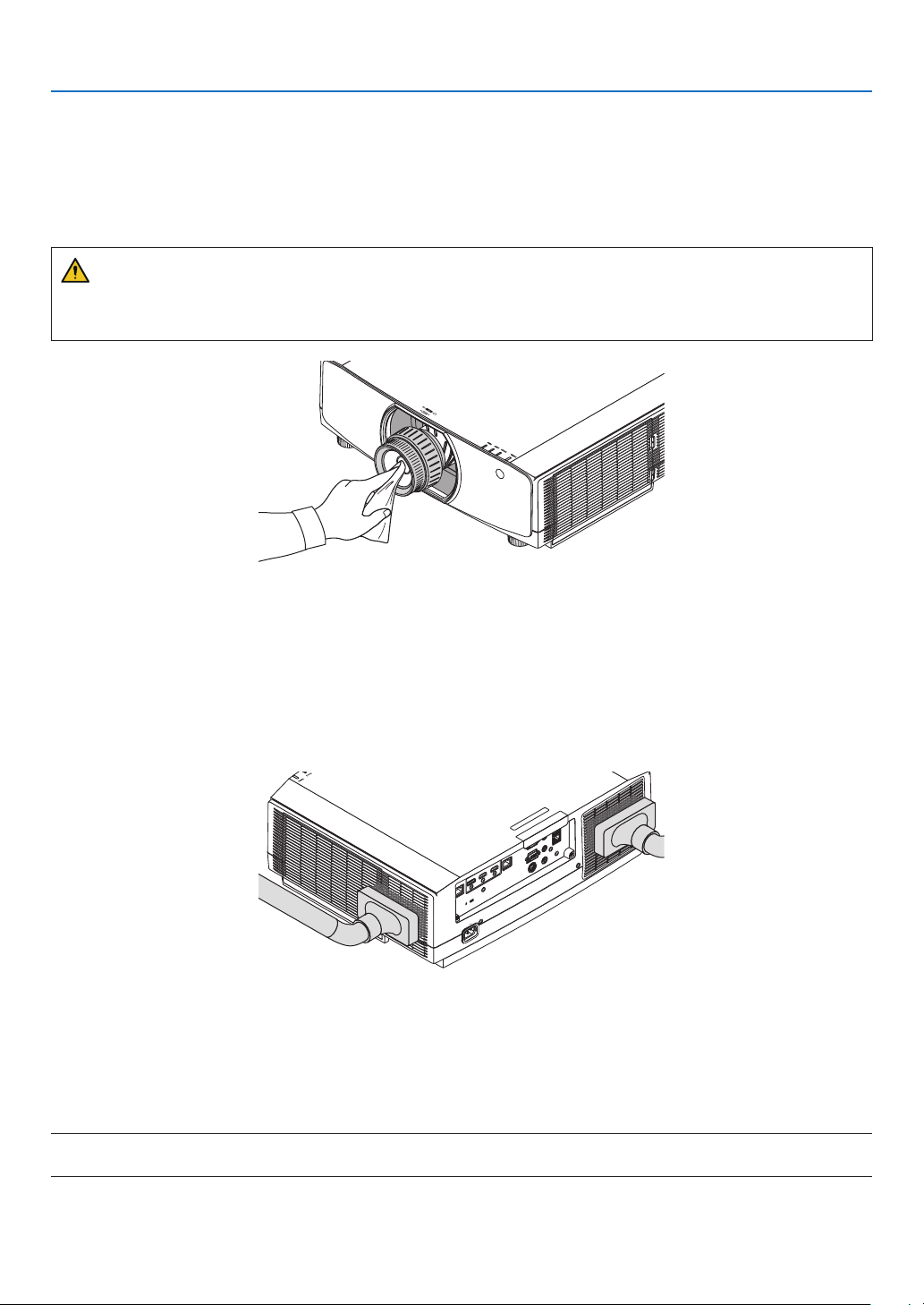
155
7. Maintenance
❷ Cleaning the Lens
• Turnofftheprojectorbeforecleaning.
• Theprojectorhasaplasticlens.Useacommerciallyavailableplasticlenscleaner.
• Donotscratchormarthelenssurfaceasaplasticlensiseasilyscratched.
• Neverusealcoholorglasslenscleanerasdoingsowillcausedamagetotheplasticlenssurface.
WARNING
• Pleasedonotuseaspraycontainingammablegastoremovedustattachedtothelens,etc.Doingsomay
resultinres.
❸ Cleaning the Cabinet
Turnofftheprojector,andunplugtheprojectorbeforecleaning.
• Useadrysoftclothtowipedustoffthecabinet.
Ifheavilysoiled,useamilddetergent.
• Neverusestrongdetergentsorsolventssuchasalcoholorthinner.
• Whencleaningtheventilationslitsorthespeakerusingavacuumcleaner,donotforcethebrushofthevacuum
cleaner into the slits of the cabinet.
Vacuum the dust off the ventilation slits.
• Cloggedventilationslitsmaycauseariseintheinternaltemperatureoftheprojector,resultinginmalfunction.
• Donotscratchorhitthecabinetwithyourngersoranyhardobjects
• Contactyourdealerforcleaningtheinsideoftheprojector.
NOTE:Donotapplyvolatileagentsuchasinsecticideonthecabinet,thelens,orthescreen.Donotleavearubberorvinylproduct
in prolonged contact with it. Otherwise the surface finish will be deteriorated or the coating may be stripped off.

156
7. Maintenance
❹ Replacing the Lamp
Whenthelampreachestheendofitslife,theLAMPindicatoronthecabinetwillblinkinorangeandthemessage“THE
LAMPHASREACHEDTHEENDOFITSUSABLELIFE.PLEASEREPLACETHELAMP.USETHESPECIFIED
LAMPFORSAFETYANDPERFORMANCE.”willappear(*).Eventhoughthelampmaystillbeworking,replacethe
lamptomaintaintheoptimalprojectorperformanceassoonaspossible.Afterreplacingthelamp,besuretoclear
the lamp hour meter. (→page134)
CAUTION
• DONOTTOUCHTHELAMPimmediatelyafterithasbeenused.Itwillbeextremelyhot.Turntheprojectoroff
andthendisconnectthepowercord.Allowatleastonehourforthelamptocoolbeforehandling.
• Usethespeciedlampforsafetyandperformance.
• DONOTREMOVEANYSCREWSexceptonelampcoverscrewandtwolamphousingscrews.Youcouldreceive
anelectricshock.
• Donotbreaktheglassonthelamphousing.
Keepngerprintsofftheglasssurfaceonthelamphousing.Leavingngerprintsontheglasssurfacemightcause
anunwantedshadowandpoorpicturequality.
• ThebarindicatorastheLAMPLIFEREMAININGshowsthepercentageofremainingbulblife.
Whentheremaininglamptimereaches0%,theLAMPLIFEREMAININGbarindicatorchangesfrom0%to100
Hoursasthegraceperiodforreplacinglampandstartscountingdown.Inthegraceperiod,theLAMPindicator
willblinkinorange.
Whenitreaches0hours,theLAMPindicatorwillstartblinkinginred.
Ifyoucontinuetousethelampafterthelampreachestheendofitslife,thelampbulbmayshatter,andpiecesof
glassmaybescatteredinthelampcase.Donottouchthemasthepiecesofglassmaycauseinjury.Ifthishap-
pens,contactyourNECdealerforlampreplacement.
*NOTE: This message will be displayed under the following conditions:
• foroneminuteaftertheprojectorhasbeenpoweredon
• whenthe (POWER)buttonontheprojectorcabinetortheSTANDBYbuttonontheremotecontrolispressed
To turn off the message, press any button on the projector cabinet or the remote control.
Optionallampandtoolsneededforreplacement:
• Phillipsscrewdriver(plus-head)
• Replacementlamp:
NP42LP
Flow of Replacing the Lamp
Step 1. Replacethelamp
Step 2. Clearthelampusagehours(→page134, 135)
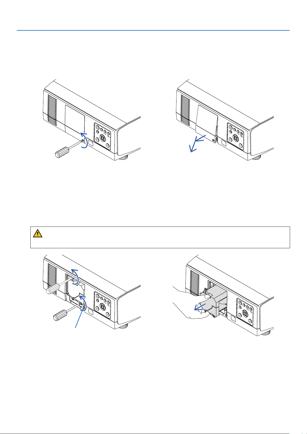
157
7. Maintenance
To replace the lamp:
1. Removethelampcover.
(1) Loosen the lamp cover screw
• Thelampcoverscrewisnotremovable.
(2) Pull the bottom of the lamp cover towards you and remove it.
2. Removethelamphousing.
(1) Loosen the two screws securing the lamp housing until the phillips screwdriver goes into a freewheeling condi-
tion.
• Thetwoscrewsarenotremovable.
• Thereisaninterlockonthiscasetopreventtheriskofelectricalshock.Donotattempttocircumventthis
interlock.
(2) Remove the lamp housing by holding it.
CAUTION:
Makesurethatthelamphousingiscoolenoughtobeforeremovingit.
Interlock
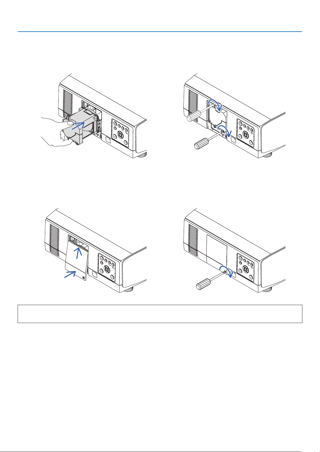
158
7. Maintenance
3. Installanewlamphousing.
(1) Insert a new lamp housing gently.
(2) Secure it in place with the two screws.
• Besuretotightenthescrews.
4. Reattachthelampcover.
(1) Insert the top edge of the lamp cover into the groove in the projector and close the lamp cover.
(2) Tighten the screw to secure the lamp cover.
• Besuretotightenthescrew.
This completes the lamp replacement.
Go on to clear the lamp usage hours.

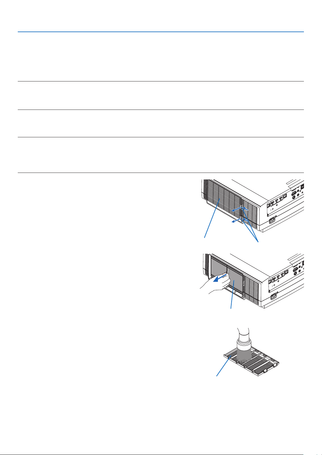
160
7. Maintenance
❺ Replacing the filters
Replacethelterevery10000usedhours.
Usabletimeofthelterisvariesdependsontheprojectorinstallationcircumstances.Ifyourprojectorisinstalledin
dustycircumstance,recommendtoreplacethelterearlierthan10000hours.
• Thereplacementlter,NP06FT,isavailableatourdealers.
NOTE:
• DONOTTOUCHTHEFILTERUNITimmediatelyaftertheprojectorhasbeenused.Turntheprojectoroffandthendisconnectthe
power cord and leave the projector cooled down enough.
• Timeforreplacingthelterisvarydependsontheoperationcircumstances.
Toreplacethelters:
NOTE:
• Beforereplacingthelters,wipeoffdustanddirtfromtheprojectorcabinet.
• Theprojectorisprecisionequipment.Keepoutdustanddirtduringlterreplacement.
• Donotwashthelterswithsoapandwater.Soapandwaterwilldamagetheltermembrane.
• Putltersintoplace.Incorrectattachmentofaltermaycausedustanddirttogetintotheinsideoftheprojector.
1. Press down two buttons and then pull the filter cover
towards you to open it.
Filter cover Button
2. Pickthecenterofthefilterunitforpullingitout.
Filter unit
3. Removedustfromthefiltercover.
Clean both outside and inside.
4. Attach a new filter into the filter unit.
Filter cover
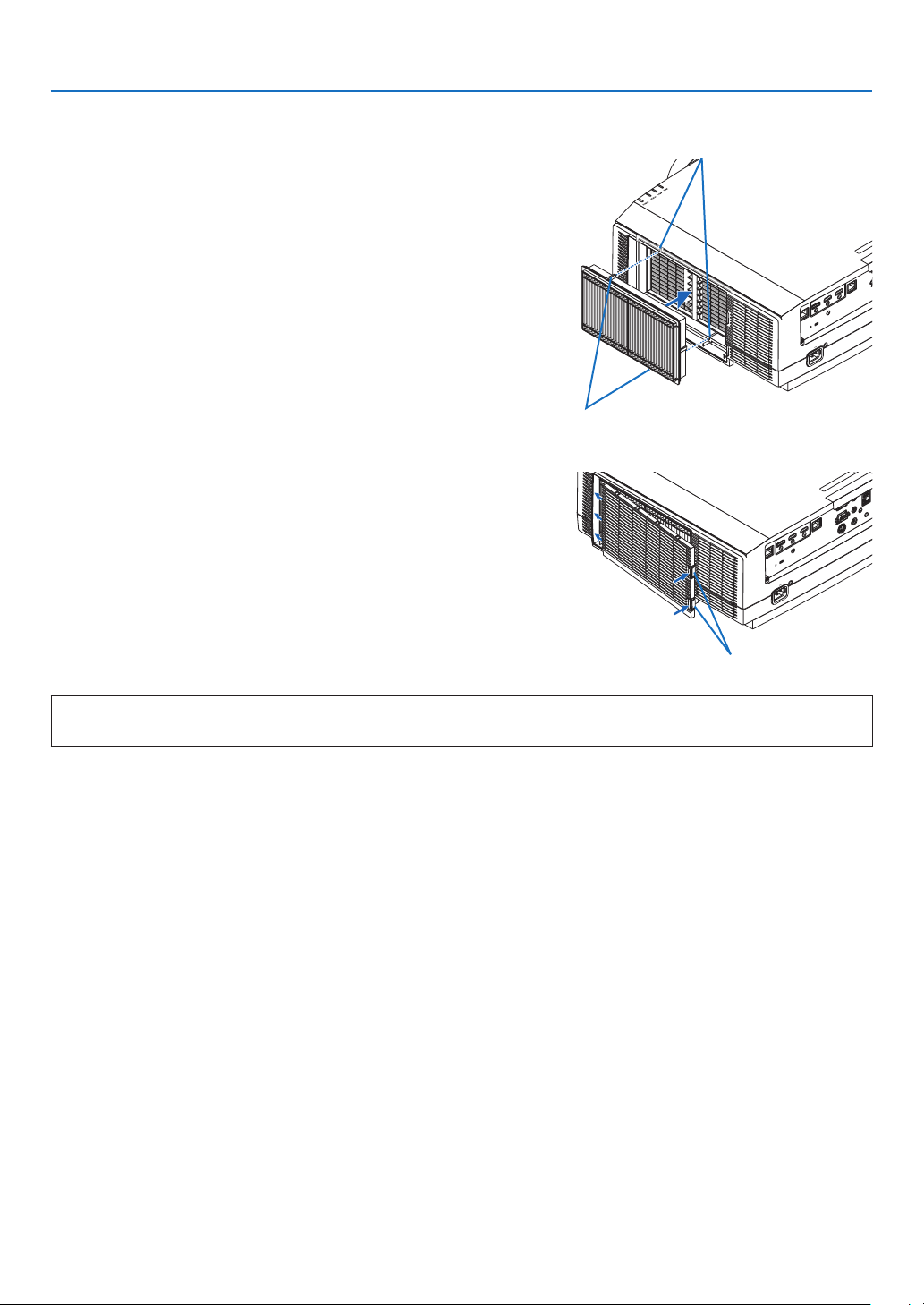
161
7. Maintenance
5. Mountthefilterunitbackontotheprojectorcabinet.
Insert the filter unit onto the projector aligning the two protru-
sions on each top and bottom of the filter unit to the groove
on the projector cabinet.
Protrusion
Groove
6. Closethefiltercover.
Keep to push the filter cover frame around the buttons until
a “click” sound is heard. The filter cover will be secured in
position.
Button
Thiscompletesthelterreplacement.
Goontoclearthelterhours.
Toclearthelterhours:
1. Place the projector where you use it.
2. Plugthepowercordintothewalloutlet,andthenturnontheprojector.
3. Clearthefilterhours.
From the menu, select [RESET] → [CLEAR FILTER HOURS] and reset the filter usage hours. (→ page 135)

162
8. Appendix
❶ Throw distance and screen size
Eightseparatebayonetstylelensescanbeusedonthisprojector.Refertotheinformationonthispageandusea
lenssuitedfortheinstallationenvironment(screensizeandthrowdistance).Forinstructionsonmountingthelens,
seepage141.
Lens types and throw distance
WUXGAType
(Unit:m)
Screensize
(inches)
Lensmodelname
NP11FL NP30ZL NP12ZL NP13ZL NP14ZL NP40ZL NP41ZL NP43ZL
30 - -
0.7-0.9 0.9-1.9 - - - -
40
0.7 - 1.0-1.3 1.2-2.5 - - - -
50
0.8 0.8-1.1 1.2-1.6 1.6-3.1 - 0.8-1.2 1.4-3.2 3.3-6.4
60 1.0 1.0-1.3 1.5-1.9 1.9-3.8 3.7-6.0 1.0-1.4 1.7-3.9 3.9-7.7
80 1.4 1.4-1.8 2.0-2.6 2.5-5.1 5.0-8.0 1.4-1.9 2.2-5.2 5.2-10.2
100 1.7 1.7-2.2 2.5-3.3 3.2-6.3 6.3-10.1 1.7-2.4 2.8-6.5 6.4-12.8
120 2.1 2.0-2.7 3.0-3.9 3.8-7.6 7.5-12.1 2.0-2.9 3.4-7.8 7.7-15.3
150 2.6 2.6-3.4 3.8-4.9 4.8-9.5 9.4-15.2 2.6-3.6 4.2-9.8 9.6-19.1
200 - 3.4-4.5 5.1-6.6 6.4-12.7 12.6-20.3 3.4-4.8 5.7-13.0 12.7-25.4
240 - 4.1-5.4 6.1-7.9 7.6-15.3 15.2-24.4 4.1-5.8 6.8-15.6 15.3-30.5
300 - 5.2-6.8 7.6-9.9 9.6-19.1 19.0-30.5 5.2-7.3 8.5-19.6 19.1-38.1
400 - 6.9-9.0 10.2-13.2 12.8-25.5 25.4-40.7 6.9-9.7 11.4-26.1 25.4-50.8
500 - 8.7-11.3 12.7-16.5 16.0-31.9 31.8-50.9 8.6-12.1 14.2-32.6 31.7-63.4
(Unit:inches)
Screensize
(inches)
Lensmodelname
NP11FL NP30ZL NP12ZL NP13ZL NP14ZL NP40ZL NP41ZL NP43ZL
30 - - 28-37 36-74 - - - -
40
26 - 38-50 48-99 - - - -
50
33 33-43 48-64 61-124 - 33-46 54-127 129-254
60 40 40-52 59-77 74-149 146-236 40-56 66-153 154-303
80 53 53-70 79-103 99-200 196-317 53-75 88-204 204-403
100 67 67-88 99-129 124-250 246-397 67-94 110-256 254-503
120 81 81-106 119-155 149-300 296-477 81-113 133-307 303-602
150 101 101-132 149-194 187-376 372-598 101-142 166-384 378-752
200 - 135-177 199-259 250-502 497-799 135-190 223-513 502-1001
240 - 163-213 239-312 301-602 598-959 163-229 267-616 601-1201
300 - 204-267 300-390 377-754 748-1200 204-286 335-770 750-1500
400 - 272-356 400-521 503-1005 1000-1602 272-382 447-1028 999-1998
500 - 341-445 501-651 629-1257 1251-2004 340-478 559-1285 1247-2497
TIP
Calculationofthethrowdistancefromthescreensize
NP11FLlensthrowdistance(inch/m)=H×0.8:26"/0.7m(min.)to101"/2.6m(max.)
NP30ZLlensthrowdistance(inch/m)=H×0.8toH×1.0:33"/0.8m(min.)to445"/11.3m(max.)
NP12ZLlensthrowdistance(inch/m)=H×1.2toH×1.5:28"/0.7m(min.)to651"/16.5m(max.)
NP13ZLlensthrowdistance(inch/m)=H×1.5toH×3.0:36"/0.9m(min.)to1257"/31.9m(max.)
NP14ZLlensthrowdistance(inch/m)=H×2.9toH×4.7:146"/3.7m(min.)to2004"/50.9m(max.)
NP40ZLlensthrowdistance(inch/m)=H×0.8toH×1.1:33"/0.8m(min.)to478"/12.1m(max.)
NP41ZLlensthrowdistance(inch/m)=H×1.3toH×3.0:54"/1.4m(min.)to1285"/32.6m(max.)
NP43ZLlensthrowdistance(inch/m)=H×3.0toH×5.9:129"/3.3m(min.)to2497"/63.4m(max.)
“H”(Horizontal)referstothescreenwidth.
*Figuresdifferbyseveral%withthetableabovebecausethecalculationisapproximate.
Ex.:Throwdistancewhenprojectingona150"screenusingtheNP13ZLlens:
Accordingtothe“ScreenSize(forreference)”table(→ page 166),H(screenwidth)=127"/323.1cm.
Thethrowdistanceis127"/323.1cm×1.5to127"/323.1cm×3.0=191"/484.7cmto381"/969.3cm(becauseofthezoomlens).

163
8. Appendix
WXGAType
(Unit:m)
Screensize
(inches)
Lensmodelname
NP11FL NP30ZL NP12ZL NP13ZL NP14ZL NP40ZL NP41ZL NP43ZL
30 - - 0.7-1.0 0.9-1.9 - - - -
40
0.7 - 1.0-1.3 1.2-2.5 - - - -
50
0.8 0.8-1.1 1.2-1.6 1.6-3.2 - 0.8-1.2 1.4-3.2 3.3-6.5
60 1.0 1.0-1.3 1.5-2.0 1.9-3.8 3.7-6.0 1.0-1.4 1.7-3.9 3.9-7.7
80 1.4 1.4-1.8 2.0-2.6 2.5-5.1 5.0-8.1 1.4-1.9 2.2-5.2 5.2-10.3
100 1.7 1.7-2.2 2.5-3.3 3.2-6.4 6.3-10.1 1.7-2.4 2.8-6.5 6.5-12.8
120 2.1 2.0-2.7 3.0-4.0 3.8-7.7 7.6-12.2 2.1-2.9 3.4-7.8 7.7-15.4
150 2.6 2.6-3.4 3.8-5.0 4.8-9.6 9.5-15.3 2.6-3.6 4.3-9.8 9.6-19.2
200 - 3.4-4.5 5.1-6.6 6.4-12.8 12.7-20.4 3.4-4.9 5.7-13.1 12.8-25.5
240 - 4.1-5.4 6.1-8.0 7.7-15.4 15.3-24.5 4.1-5.8 6.8-15.7 15.3-30.6
300 - 5.2-6.8 7.7-10.0 9.6-19.2 19.1-30.7 5.2-7.3 8.6-19.6 19.1-38.2
400 - 6.9-9.0 10.2-13.3 12.8-25.7 25.5-40.9 6.9-9.7 11.4-26.2 25.5-51.0
500 - 8.7-11.3 12.8-16.7 16.0-32.1 31.9-51.2 8.7-12.2 14.3-32.8 31.8-63.7
(Unit:inches)
Screensize
(inches)
Lensmodelname
NP11FL NP30ZL NP12ZL NP13ZL NP14ZL NP40ZL NP41ZL NP43ZL
30 - - 29-38 36-74 - - - -
40
26 - 39-51 49-99 - - - -
50
33 33-43 49-64 61-125 - 33-47 55-128 130-255
60 40 40-52 59-77 74-150 147-238 40-56 66-153 155-305
80 53 53-70 79-103 99-201 197-318 53-75 88-205 205-405
100 67 67-88 99-130 125-251 248-399 67-95 111-257 255-505
120 81 81-106 120-156 150-302 298-480 81-114 134-308 304-605
150 101 101-132 150-195 188-378 374-601 101-143 167-386 379-755
200 - 135-177 201-261 252-504 500-803 136-191 224-515 504-1005
240 - 163-213 241-314 302-606 601-965 163-230 269-618 604-1205
300 - 204-267 302-393 378-757 752-1207 204-287 337-773 753-1506
400 - 272-356 403-524 505-1011 1005-1611 273-384 449-1031 1003-2006
500 - 341-445 504-656 632-1264 1257-2015 342-480 562-1289 1252-2507
TIP
Calculationofthethrowdistancefromthescreensize
NP11FLlensthrowdistance(inch/m)=H×0.8:26"/0.7m(min.)to102"/2.6m(max.)
NP30ZLlensthrowdistance(inch/m)=H×0.8toH×1.0:33"/0.8m(min.)to445"/11.3m(max.)
NP12ZLlensthrowdistance(inch/m)=H×1.2toH×1.5:29"/0.7m(min.)to656"/16.7m(max.)
NP13ZLlensthrowdistance(inch/m)=H×1.5toH×3.0:36"/0.9m(min.)to1264"/32.1m(max.)
NP14ZLlensthrowdistance(inch/m)=H×2.9toH×4.7:147"/3.7m(min.)to2015"/51.2m(max.)
NP40ZLlensthrowdistance(inch/m)=H×0.8toH×1.1:33"/0.8m(min.)to480"/12.2m(max.)
NP41ZLlensthrowdistance(inch/m)=H×1.3toH×3.0:55"/1.4m(min.)to1289"/32.8m(max.)
NP43ZLlensthrowdistance(inch/m)=H×3.0toH×6.0:130"/3.3m(min.)to2507"/63.7m(max.)
“H”(Horizontal)referstothescreenwidth.
*Figuresdifferbyseveral%withthetableabovebecausethecalculationisapproximate.
Ex.:Throwdistancewhenprojectingona150"screenusingtheNP13ZLlens:
Accordingtothe“ScreenSize(forreference)”table(→ page 166),H(screenwidth)=127"/323.1cm.
Thethrowdistanceis127"/323.1cm×1.5to127"/323.1cm×3.0=191"/484.7cmto381"/969.3cm(becauseofthezoomlens).

164
8. Appendix
XGAType
(Unit:m)
Screensize
(inches)
Lensmodelname
NP11FL NP30ZL NP12ZL NP13ZL NP14ZL NP40ZL NP41ZL NP43ZL
30 - - 0.7-0.9 0.9-1.8 - - - -
40
0.6 - 0.9-1.2 1.2-2.4 - - - -
50
0.8 0.8-1.1 1.2-1.6 1.5-3.0 - 0.8-1.1 1.3-3.1 3.2-6.2
60 1.0 1.0-1.3 1.4-1.9 1.8-3.7 3.6-5.8 1.0-1.4 1.6-3.7 3.8-7.4
80 1.3 1.3-1.7 1.9-2.5 2.4-4.9 4.8-7.8 1.3-1.8 2.2-5.0 5.0-9.9
100 1.6 1.6-2.1 2.4-3.2 3.0-6.1 6.0-9.7 1.6-2.3 2.7-6.3 6.2-12.3
120 2.0 2.0-2.6 2.9-3.8 3.7-7.4 7.3-11.7 2.0-2.8 3.3-7.5 7.4-14.8
150 2.5 2.5-3.2 3.7-4.8 4.6-9.2 9.1-14.7 2.5-3.5 4.1-9.4 9.3-18.4
160 2.7
200 - 3.3-4.3 4.9-6.4 6.1-12.3 12.2-19.6 3.3-4.7 5.5-12.5 12.3-24.5
240 - 4.0-5.2 5.9-7.7 7.4-14.8 14.7-23.6 4.0-5.6 6.6-15.1 14.7-29.4
300 - 5.0-6.5 7.4-9.6 9.2-18.5 18.4-29.5 5.0-7.0 8.2-18.8 18.4-36.7
400 - 6.7-8.7 9.8-12.8 12.3-24.7 24.5-39.3 6.7-9.4 11.0-25.1 24.5-48.9
500 - 8.4-10.9 12.3-16.0 15.4-30.9 30.7-49.2 8.3-11.7 13.7-31.4 30.5-61.1
(Unit:inches)
Screensize
(inches)
Lensmodelname
NP11FL NP30ZL NP12ZL NP13ZL NP14ZL NP40ZL NP41ZL NP43ZL
30 - - 27-36 35-71 - - - -
40
26 - 37-49 47-95 - - - -
50
33 31-42 47-61 59-120 - 31-45 52-122 125-245
60 40 38-50 56-74 71-144 141-228 38-54 63-147 149-293
80 53 51-67 76-99 96-193 189-306 51-72 85-197 197-389
100 67 65-85 95-125 120-242 238-384 64-91 107-246 245-485
120 81 78-102 115-150 144-290 286-461 78-109 128-296 292-581
150 101 98-128 144-188 181-363 359-578 97-137 161-370 364-725
160 105
200 - 131-171 193-251 242-485 481-772 130-183 215-494 484-965
240 - 157-205 231-301 291-582 578-927 157-220 258-593 580-1157
300 - 197-257 290-377 364-728 723-1160 196-276 323-742 723-1446
400 - 263-343 387-503 486-972 966-1549 262-368 432-989 963-1926
500 - 329-430 484-630 608-1215 1209-1937 328-461 540-1237 1202-2407
TIP
Calculationofthethrowdistancefromthescreensize
NP11FLlensthrowdistance(inch/m)=H×0.8:25"/0.6m(min.)to105"/2.7m(max.)
NP30ZLlensthrowdistance(inch/m)=H×0.8toH×1.1:31"/0.8m(min.)to430"/10.9m(max.)
NP12ZLlensthrowdistance(inch/m)=H×1.2toH×1.6:27"/0.7m(min.)to484"/16.0m(max.)
NP13ZLlensthrowdistance(inch/m)=H×1.5toH×3.0:35"/0.9m(min.)to1215"/30.9m(max.)
NP14ZLlensthrowdistance(inch/m)=H×3.0toH×4.8:141"/3.6m(min.)to1937"/49.2m(max.)
NP40ZLlensthrowdistance(inch/m)=H×0.8toH×1.1:31"/0.8m(min.)to461"/11.7m(max.)
NP41ZLlensthrowdistance(inch/m)=H×1.3toH×3.1:52"/1.3m(min.)to1237"/31.4m(max.)
NP43ZLlensthrowdistance(inch/m)=H×3.1toH×6.1:125"/3.2m(min.)to2407"/61.1m(max.)
“H”(Horizontal)referstothescreenwidth.
*Figuresdifferbyseveral%withthetableabovebecausethecalculationisapproximate.
Ex.:Throwdistancewhenprojectingona150"screenusingtheNP13ZLlens:
Accordingtothe“ScreenSize(forreference)”table(→ page 166),H(screenwidth)=120"/304.8cm.
Thethrowdistanceis120"/304.8cm×1.5to120"/304.8cm×3.0=180"/457.2cmto360"/914.4cm(becauseofthezoomlens).
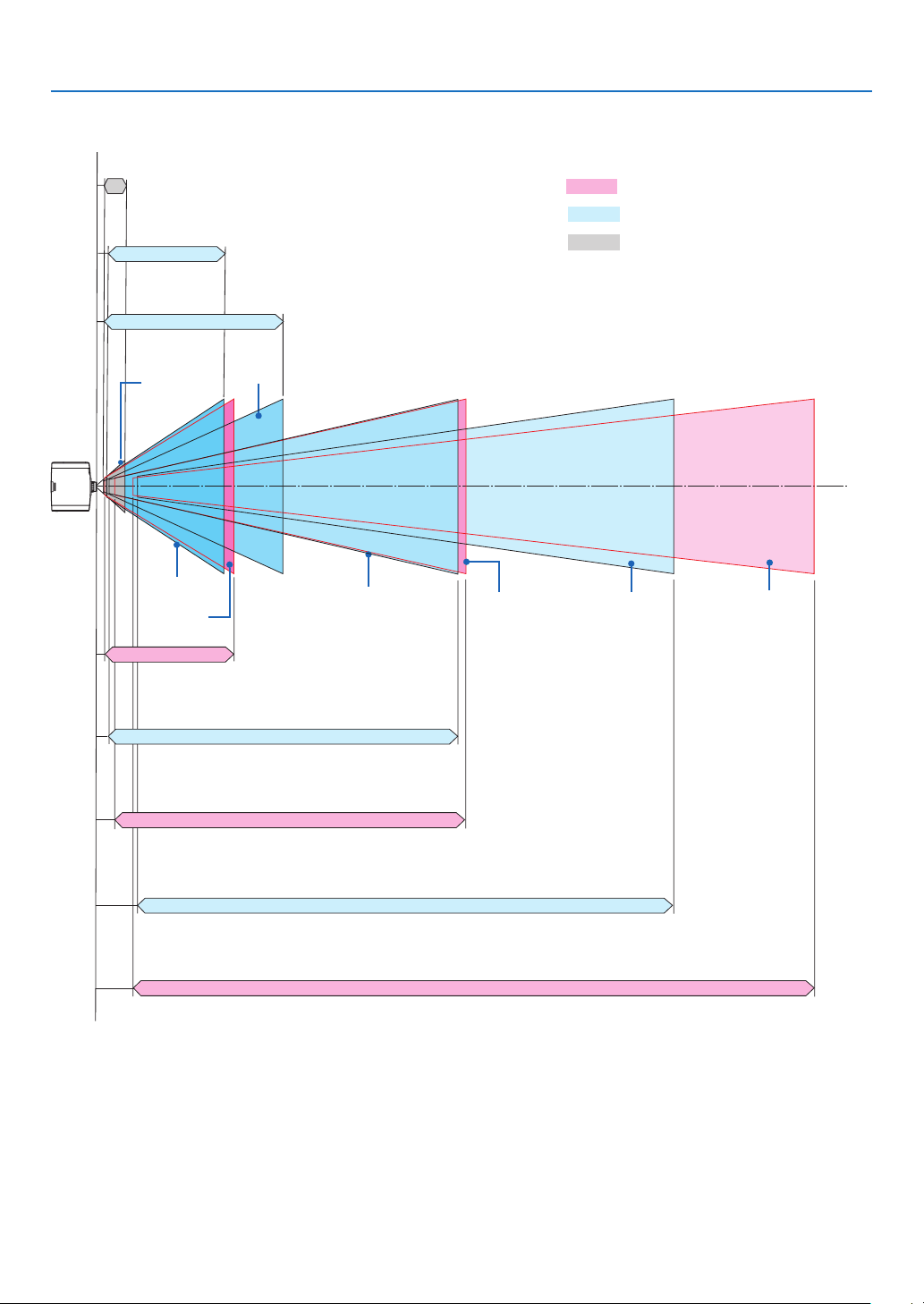
165
8. Appendix
Projection range for the different lenses
NP12ZL
NP11FL
NP30ZL
NP14ZL
NP43ZL
NP41ZL
NP40ZL
NP13ZL
40-150"
30-500"
50-500"
50-500"
30-500" 50-500" 50-500"60-500"
WUXGAType:26"-101"/0.7–2.6m
WXGAType:26"-102"/0.7–2.6m
XGAType:0.6–2.7m(max.160")
WUXGAType:33"-445"/0.8–11.3m
WXGAType:33"-445"/0.8–11.3m
XGAType:31"-430"/0.8–10.9m
WUXGAType:28"-651"/0.7–16.5m
WXGAType:29"-656"/0.7–16.7m
XGAType:27"-630"/0.7–16.0m
WUXGAType:36"-1257"/0.9-31.9m
WXGAType:36"-1264"/0.9–32.1m
XGAType:35"-1215"/0.9-30.9m
WUXGAType:33"-478"/0.8-12.1m
WXGAType:33"-480"/0.8-12.2m
XGAType:31"-461"/0.8-11.7m
WUXGAType:54"-1285"/1.4-32.6m
WXGAType:55"-1289"/1.4-32.8m
XGAType:52"-1237"/1.3-31.4m
WUXGAType:146"-2004"/3.7–50.9m
WXGAType:147"-2015"/3.7–51.2m
XGAType:141"-1937"/3.6–49.2m
WUXGAType:129"-2497"/3.3-63.4m
WXGAType:130"-2507"/3.3-63.7m
XGAType:125"-2407"/3.2-61.1m
Motorizedzoom/Motorizedfocus
Manualzoom/Manualfocus
Manual focus
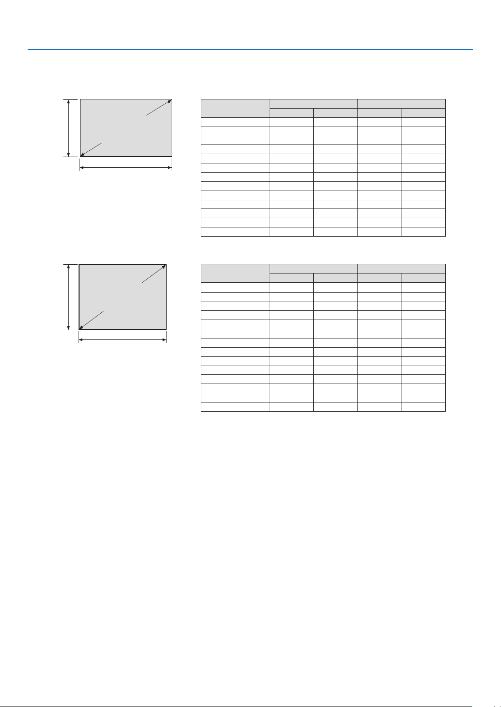
166
8. Appendix
Tables of screen sizes and dimensions
WUXGAType/WXGAType
Screen
height
Screen width
16:10 screen size (di-
agonal)
Size(inches) Screenwidth Screenheight
(inches) (cm) (inches) (cm)
30 25 64.6 16 40.4
40 34 86.2 21 53.8
50 42 107.7 26 67.3
60 51 129.2 32 80.8
80 68 172.3 42 107.7
100 85 215.4 53 134.6
120 102 258.5 64 161.5
150 127 323.1 79 201.9
200 170 430.8 106 269.2
240 204 516.9 127 323.1
300 254 646.2 159 403.9
400 339 861.6 212 538.5
500 424 1077.0 265 673.1
XGAType
Screen
height
Screen width
4:3 screen size (di-
agonal)
Size(inches) Screenwidth Screenheight
(inches) (cm) (inches) (cm)
30 24 61.0 18 45.7
40 32 81.3 24 61.0
50 40 101.6 30 76.2
60 48 121.9 36 91.4
80 64 162.6 48 121.9
100 80 203.2 60 152.4
120 96 243.8 72 182.9
150 120 304.8 90 228.6
160 128 325.1 96 243.8
200 160 406.4 120 304.8
240 192 487.7 144 365.8
300 240 609.6 180 457.2
400 320 812.8 240 609.6
500 400 1016.0 300 762.0
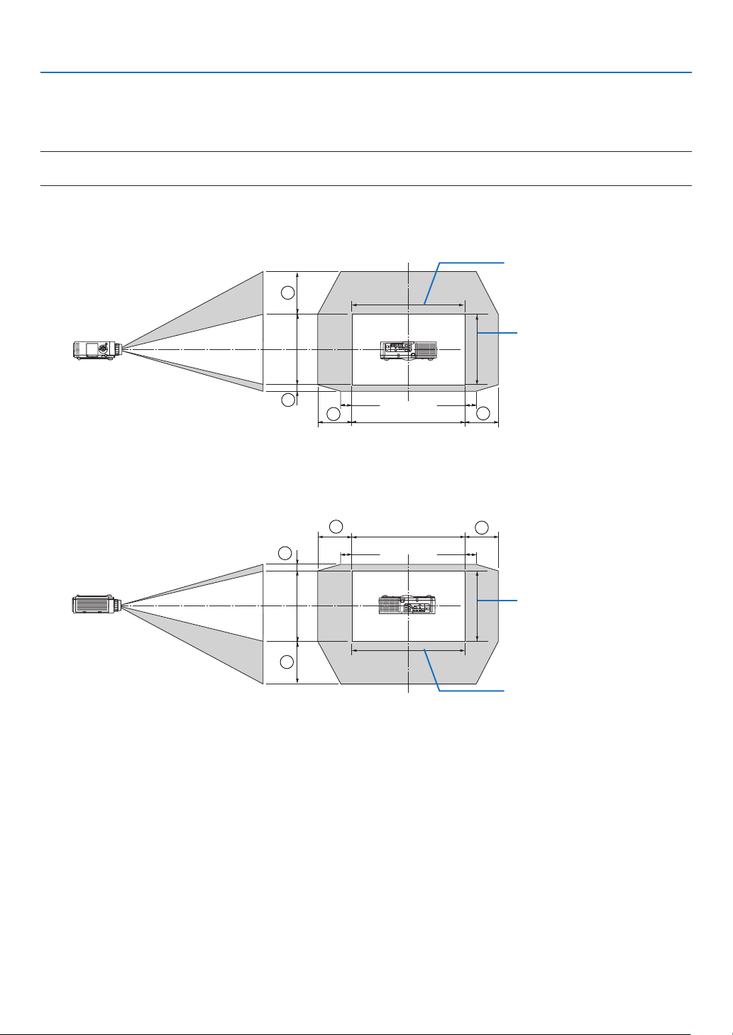
167
8. Appendix
Lens shifting range
Thisprojectorisequippedwithalensshiftfunctionforadjustingthepositionoftheprojectedimagebybuttons.The
lenscanbeshiftedwithintherangeshownbelow.
NOTE:
• UseNP11FLatthehomeposition.
* Refertothelensshifttableonthenextpageforthedrawingnumberofthelensshiftrange.
Desk/front projection
100%V
100%H
1
2
3
4
10%H 10%H
Width of projected image
Height of projected image
Descriptionofsymbols:Vindicatesvertical(heightoftheprojectedimage),Hindicateshorizontal(widthofthepro-
jectedimage).
Ceiling/front projector
100%V
100%H
10%H
10%H
1
2
3
4
Height of projected image
Width of projected image

168
8. Appendix
Lens shift table
Applicable
type
Drawing
number
Lensunit
NP30ZL NP12ZL NP13ZL NP14ZL NP40ZL NP41ZL NP43ZL
WUXGAType
①
50%V 50%V 50%V 50%V 50%V 50%V 50%V
②
10%V 10%V 10%V 10%V 10%V 10%V 10%V
③
20%H 30%H 30%H* 30%H 20%H 20%H 20%H
④
20%H 30%H 30%H* 30%H 20%H 20%H 20%H
WXGAType
①
50%V 60%V 60%V 60%V 50%V 50%V 50%V
②
10%V 10%V 10%V 10%V 10%V 10%V 10%V
③
20%H 30%H 30%H 30%H 20%H 20%H 20%H
④
20%H 30%H 30%H 30%H 20%H 20%H 20%H
XGAType
①
35%V 50%V 50%V 50%V 35%V 35%V 35%V
②
10%V 10%V 10%V 10%V 10%V 10%V 10%V
③
20%H 30%H 30%H 30%H 20%H 20%H 20%H
④
20%H 30%H 30%H 30%H 20%H 20%H 20%H
* ForWUXGAType,theshiftrangeinthehorizontaldirectionisupto15%Hwhenusingthelensunit“NP13ZL”toprojectascreen
exceedingModel150.
Ex.:Whenprojectingona150"screen
TheexplanationisforaXGATypeprojector(4:3panel)withaNP12ZLlenstted.
• PleasereplacethescreendimensionsandmaximumshiftvalueinthecalculationsfortheWXGATypeandWUXGA
Typeprojectors(16:10panel)aswell.
Accordingtothetablesofscreensizesanddimensions(→page166),H=120"(304.8cm),V=90"(228.6cm).
Adjustmentrangeintheverticaldirection:Theprojectedimagecanbemovedupwards0.5×90"(228.6cm)=45"
(114cm),,downwards0.1×90"(228.6cm)=9"(22cm)(whenthelensisatthecenterposition).Foraceiling/front
installation,theaboveguresareinverted.
Adjustmentrangeinthehorizontaldirection:Theprojectedimagecanbemovedtotheleft0.3×120"(304.8cm)=36"
(91cm),totheright0.3×120"(304.8cm)=36"(91cm).
*Figuresdifferbyseveral%becausethecalculationisapproximate.

169
8. Appendix
❷ Compatible Input Signal List
HDMI/HDBaseT
Signal Resolution(dots) AspectRatio RefreshRate(Hz)
VGA 640 × 480 4 : 3 60/72/75/85/iMac
SVGA 800 × 600 4 : 3 56/60/72/75/85/iMac
XGA 1024 × 768 *
1
4 : 3 60/70/75/85/iMac
HD 1280 × 720 *
2
16 : 9 60
WXGA
1280 × 768 *
2
15 : 9 60
1280 × 800 *
2
16 : 10 60
Quad-VGA 1280 × 960 4 : 3 60
SXGA 1280 × 1024 5 : 4 60
FWXGA
1360 × 768 16 : 9 60
1366 × 768 16 : 9 60
SXGA+ 1400 × 1050 4 : 3 60
WXGA+ 1440 × 900 16 : 10 60
WXGA++ 1600 × 900 16 : 9 60
WSXGA+ 1680 × 1050 16 : 10 60
UXGA 1600 × 1200 *
3
4 : 3 60
FullHD 1920 × 1080 *
3
16 : 9 60
WUXGA 1920 × 1200 *
3
16 : 10 60(ReducedBlanking)
2K 2048 × 1080 17 : 9 60
WQHD
iMac27"
2560 × 1440 16 : 9 60
WQXGA 2560 × 1600 16 : 10
60(ReducedBlanking)
4K
3840 × 2160 16 : 9
24/25/30/50/60
4096 × 2160 17 : 9 24/25/30/50/60
HDTV(1080p) 1920 × 1080 *
3
16 : 9 24/25/30/50/60
HDTV(1080i) 1920 × 1080 *
3
16 : 9 48/50/60
HDTV(720p) 1280 × 720 *
2
16 : 9 50/60
SDTV(480p) 720/1440 × 480 4:3/16:9 60
SDTV(576p) 720/1440 × 576 4:3/16:9 50
SDTV(480i) 1440 × 480 4:3/16:9 60
SDTV(576i) 1440 × 576 4:3/16:9 50
DisplayPort
Signal Resolution(dots) AspectRatio RefreshRate(Hz)
VGA 640 × 480 4 : 3 60
SVGA 800 × 600 4 : 3 60
XGA 1024 × 768 *
1
4 : 3 60
HD 1280 × 720 *
2
16 : 9 60
WXGA
1280 × 768 *
2
15 : 9 60
1280 × 800 *
2
16 : 10 60
Quad-VGA 1280 × 960 4 : 3 60
SXGA 1280 × 1024 5 : 4 60
FWXGA
1360 × 768 16 : 9 60
1366 × 768 16 : 9 60
SXGA+ 1400 × 1050 4 : 3 60
WXGA+ 1440 × 900 16 : 10 60
WXGA++ 1600 × 900 16 : 9 60
WSXGA+ 1680 × 1050 16 : 10 60
UXGA 1600 × 1200 *
3
4 : 3 60
FullHD 1920 × 1080 *
3
16 : 9 60
WUXGA 1920 × 1200 *
3
16 : 10 60(ReducedBlanking)
2K 2048 × 1080 17 : 9 60
WQHD
iMac27"
2560 × 1440 16 : 9 60
WQXGA 2560 × 1600 16 : 10
60(ReducedBlanking)
4K
3840 × 2160 16 : 9 24/25/30
4096 × 2160 17 : 9 24/25/30
HDTV(1080p) 1920 × 1080 16 : 9 24/25/30/50/60
HDTV(720p) 1280 × 720 16 : 9 50/60
SDTV(480i/p) 720/1440 × 480 4:3/16:9 60
SDTV(576i/p) 720/1440 × 576 4:3/16:9 50

170
8. Appendix
Analog RGB
Signal Resolution(dots) AspectRatio RefreshRate(Hz)
VGA 640 × 480 4 : 3 60/72/75/85/iMac
SVGA 800 × 600 4 : 3 56/60/72/75/85/iMac
XGA 1024 × 768 *
1
4 : 3 60/70/75/85/iMac
XGA+ 1152 × 864 4 : 3 75
HD 1280 × 720 *
2
16 : 9 60
WXGA
1280 × 768 *
2
15 : 9 60/75/85
1280 × 800 *
2
16 : 10 60/75/85
Quad-VGA 1280 × 960 4 : 3 60/85
SXGA 1280 × 1024 5 : 4 60/75/85
FWXGA
1360 × 768 16 : 9 60
1366 × 768 16 : 9 60
SXGA+ 1400 × 1050 4 : 3 60/75
WXGA+ 1440 × 900 16 : 10 60/75/85
WXGA++ 1600 × 900 16 : 9 60
UXGA 1600 × 1200 *
3
4 : 3 60
WSXGA+ 1680 × 1050 16 :
10 60
FillHD 1920 × 1080 *
3
16 : 9 60
WUXGA 1920 × 1200 *
3
16 : 10 60(ReducedBlanking)
2K 2048 × 1080 17 : 9 60
FullHD 1920 × 1080 *
3
16 : 9 60
MAC13" 640 × 480 4 : 3 67
MAC16" 832 × 624 4 : 3 75
MAC19" 1024 × 768 *
1
4 : 3 75
MAC21" 1152 × 870 4 : 3 75
MAC23" 1280 × 1024 5 : 4 65
Analog Component
Signal Resolution(dots) AspectRatio RefreshRate(Hz)
HDTV(1080p) 1920 × 1080 16 : 9 50/60
HDTV(1080i) 1920 × 1080 16 : 9 48/50/60
HDTV(720p) 1280 × 720 16 : 9 50/60
SDTV(480p) 720 × 480 4:3/16:9 60
SDTV(576p) 720 × 576 4:3/16:9 50
SDTV(480i) 720 × 480 4:3/16:9 60
SDTV(576i) 720 × 576 4:3/16:9 50
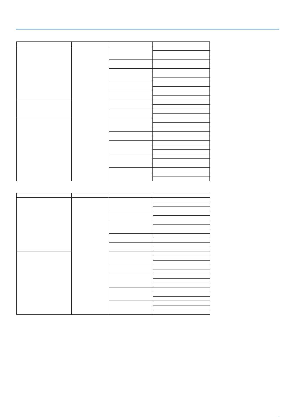
171
8. Appendix
HDMI/HDBaseT 3D
SignalResolution(dots) AspectRatio RefreshRate(Hz) 3DFormat
1920 × 1080p
16 : 9
23.98/24
FramePacking
SideBySide(Half)
TopAndBottom
25
SideBySide(Half)
TopAndBottom
29.97/30
FramePacking
SideBySide(Half)
TopAndBottom
50
SideBySide(Half)
TopAndBottom
59.94/60
SideBySide(Half)
TopAndBottom
1920 × 1080i
50
SideBySide(Half)
TopAndBottom
59.94/60
SideBySide(Half)
TopAndBottom
1280 × 720p
23.98/24
FramePacking
SideBySide(Half)
TopAndBottom
25
SideBySide(Half)
TopAndBottom
29.97/30
FramePacking
SideBySide(Half)
TopAndBottom
50
FramePacking
SideBySide(Half)
TopAndBottom
59.94/60
FramePacking
SideBySide(Half)
TopAndBottom
DisplayPort 3D
SignalResolution(dots) AspectRatio RefreshRate(Hz) 3DFormat
1920 × 1080p
16 : 9
23.98/24
FramePacking
SideBySide(Half)
TopAndBottom
25
SideBySide(Half)
TopAndBottom
29.97/30
FramePacking
SideBySide(Half)
TopAndBottom
50
SideBySide(Half)
TopAndBottom
59.94/60
SideBySide(Half)
TopAndBottom
1280 × 720p
23.98/24
FramePacking
SideBySide(Half)
TopAndBottom
25
SideBySide(Half)
TopAndBottom
29.97/30
FramePacking
SideBySide(Half)
TopAndBottom
50
FramePacking
SideBySide(Half)
TopAndBottom
59.94/60
FramePacking
SideBySide(Half)
TopAndBottom
*1 NativeresolutiononXGAType
*2 NativeresolutiononWXGAType
*3 NativeresolutiononWUXGAType
• Signalsexceedingtheprojector’sresolutionarehandledwithAdvancedAccuBlend.
• WithAdvancedAccuBlend,thesizeofcharactersandruledlinesmaybeunevenandcolorsmaybeblurred.
• Uponshipment,theprojectorissetforsignalswithstandarddisplayresolutionsandfrequencies,butadjustmentsmayberequired
dependingonthetypeofcomputer.
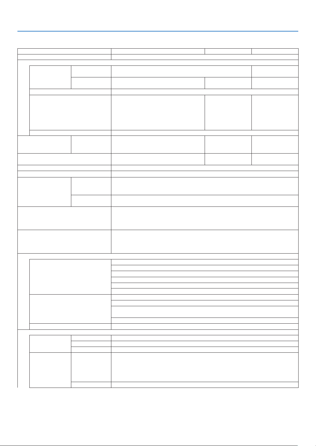
172
8. Appendix
❸ Specifications
Model name PA803U/PA723U/PA653U PA853W/PA703W PA903X
Method
Threeprimarycolorliquidcrystalshutterprojectionmethod
Specicationsofmainparts
Liquidcrystal
panel
Size 0.76"(withMLA)×3(aspectratio:16:10) 0.79"(withMLA)×3
(aspectratio:4:3)
Pixels
(*1)
2,304,000(1920dots×1200lines) 1,024,000(1280
dots×800lines)
786,432(1024dots
×768lines)
Projection lenses
Refertothespecicationsofoptionlens(→ 174page)
Lightsource PA803U:420W(280WwhenECOmode
ison)
PA723U:400W(280WwhenECOmode
ison)
PA653U:370W(280WwhenECOmode
ison)
PA853W:420W
(280WwhenECO
modeison)
PA703W:370W
(280WwhenECO
modeison)
420W(280Wwhen
ECOmodeison)
Opticaldevice Integrator,DichroicMirror,XDP
Lightoutput
(*2)
(*3)
ECOOFF PA803U:8000lm
PA723U:7200lm
PA653U:6500lm
PA853W:8500lm
PA703W:7000lm
9000lm
Contrastratio
(*2)
(allwhite/allblack) PA803U:10000:1
PA723U/PA653U:8000:1
PA853W:10000:1
PA703W:8000:1
10000:1
Screensize(throwdistance) 30"to500"(throwdistancedependsonlens)
Colorreproducibility 10-bitcolorprocessing(approx.1.07billioncolors)
Scanningfrequency Horizontal Analog:15kHz,24to100kHz(24kHzorgreaterforRGBinputs),conformingto
VESAstandards
Digital:15kHz,24to153kHz,conformingtoVESAstandards
Vertical Analog:48Hz,50to85Hz,100,120HzconformingtoVESAstandards
Digital:24,25,30,48Hz,50to85Hz,100,120HzconformingtoVESAstandards
Main adjustment functions
ZOOM,FOCUS,LENSSHIFT(Refertothespecicationsofoptionlens→ 174
page),inputsignalswitching(HDMI1/HDMI2/DisplayPort/COMPUTER/HDBaseT),
autoimageadjustment,pictureenlarging,picturepositionadjustment,muting(both
videoandaudio),poweron/standby,on-screendisplay/selection,etc.
Max.displayresolution(horizontal×
vertical)
AnalogWUXGA(1920×1200)withAdvancedAccuBlendPixelclockfrequency:less
than165MHz
DigitalQuadHD(4096×2160)withAdvancedAccuBlendPixelclockfrequency:less
than600MHz(HDBaseT:300MHz)
Inputsignals
R,G,B,H,V
RGB:0.7Vp-p/75Ω
Y:1.0Vp-p/75Ω(withNegativePolaritySync)
Cb,Cr(Pb,Pr):0.7Vp-p/75Ω
H/VSync:4.0Vp-p/TTL
CompositeSync:4.0Vp-p/TTL
SynconG:1.0Vp-p/75Ω(withSync)
Component
Y:1.0Vp-p/75Ω(withSync)
Cb,Cr(Pb,Pr):0.7Vp-p/75Ω
DTV:480i,480p,720p,1080i,1080p(60Hz)
576i,576p,720p,1080i(50Hz)
DVD:Progressivesignal(50/60Hz)
Audio
0.5Vrms/22kΩorgreater
Input/outputconnectors
Computer/Com-
ponent
Video input MiniD-Sub15-pin×1
Audioinput Stereominijack×1
Audiooutput Stereominijack×1(commonforallsignals)
HDMI Video input HDMI
®
ConnectortypeA×2
RJ-450×1,100BASE-TXcompatible
DeepColor(colordepth):8-/10-/12-bitcompatible
Colorimetry:RGB,YCbCr444,YCbCr422,YCbCr420,REC2020,REC709,REC601
SupportsLipSync,HDCP
(*4)
,4KHDRand3D
Audioinput HDMI:Samplingfrequency–32/44.1/48kHz,Samplingbits–16/20/24bits
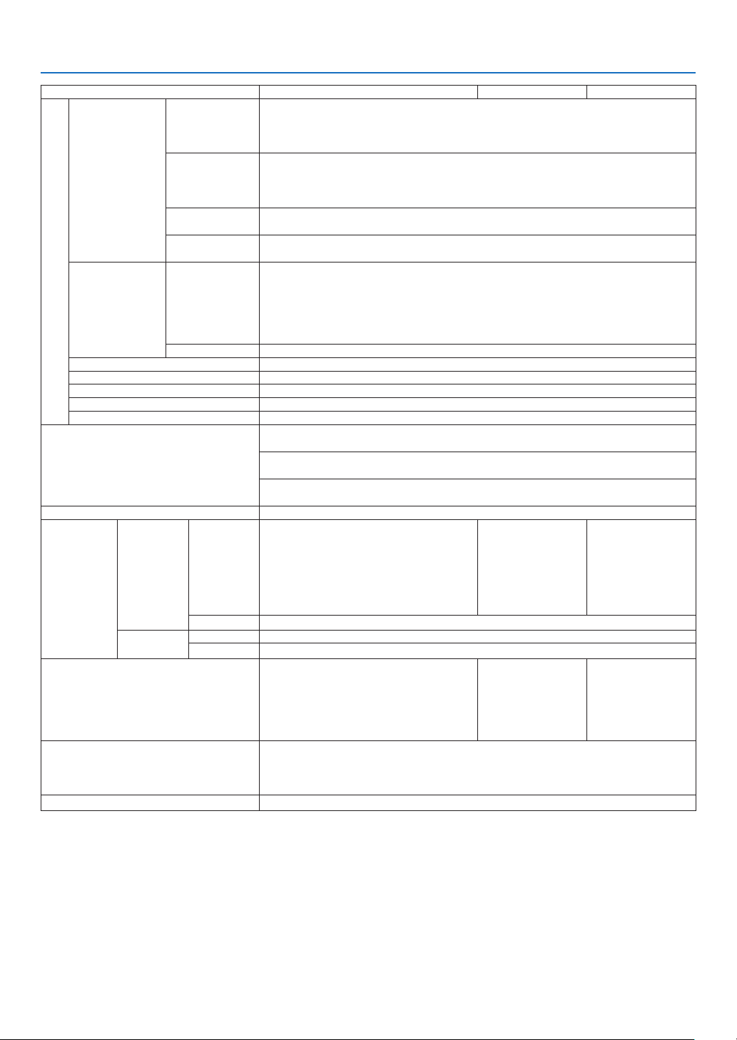
173
8. Appendix
Model name PA803U/PA723U/PA653U PA853W/PA703W PA903X
HDBaseT/Eth-
ernet
Video input
DeepColor(colordepth):Support8/10/12bits
Colorimetry:SupportRGB,YCbCr444,YCbCr422,YCbCr420,REC2020,REC709,
REC601
SupportLipSync,HDCP
(*4)
,4K,3D,HDR
Video output RJ-45x1,100BASE-TX
DeepColor(colordepth):Support8/10/12bits
Colorimetry:SupportRGB,YCbCr444,YCbCr422,REC709,REC601
SupportLipSync,HDCP
(*4)
,4K,3D
Audioinput Samplingfrequency:32/44.1/48kHz
Samplingbit:16/20/24bit
Audiooutput Samplingfrequency:32/44.1/48kHz
Samplingbit:16/20/24bits
DisplayPort Video input DisplayPort×1
Datarate:5.4Gbps/2.7Gbps/1.62Gbps
No.lanes:1lane/2lanes/4lanes
Colordepth:8bits,10bits,12bits
Colorimetry:RGB,YCbCr444,YCbCr422,REC709,REC601
HDCPcompatible
(*4)
Audioinput DisplayPort:Samplingfrequency–32/44.1/48kHz,Samplingbits–16/20/24bits
PCcontrolterminal D-Sub9-pin×1
USBport USBtypeA×1
Ethernet/LAN/HDBaseTport RJ-45×1,Supports10BASE-T/100BASE-TX
Remoteterminal Stereominijack×1
3DSYNCoutputterminal 5V/10mA,synchronizedsignaloutputfor3Duse
Usageenvironment Operatingtemperature:41to104°F(5to40°C)
(*5)
Operatinghumidity:20to80%(withnocondensation)
Storagetemperature:14to122°F(-10to50°C)
Storagehumidity:20to80%(withnocondensation)
Operatingaltitude:0to3650m/12000feet
(1700to3650m/5500to12000feet:Set[FANMODE]to[HIGHALUTITUDE])
Power supply 100-240VAC,50/60Hz
Power con-
sumption
Ecomode OFF PA803U:566W(100-130VAC)/542W
(200-240VAC)
PA723U:542W(100-130VAC)/518W
(200-240VAC)
PA653U:506W(100-130VAC)/482W
(200-240VAC)
PA853W:566W
(100-130VAC)/542
W(200-240VAC)
PA703W:506W
(100-130VAC)/
482W(200-240V
AC)
566W(100-130V
AC)/542W(200-
240VAC)
ON 390W(100-130VAC)/376W(200-240VAC)
STANDBY Link-up 0.15W(100-130VAC)/0.21W(200-240VAC)
Link-down 0.11W(100-130VAC)/0.16W(200-240VAC)
Ratedinputcurrent PA803U:2.6A(100-130V)/6.2A(200-
240V)
PA723U:2.5A(100-130V)/6.0A(200-
240V)
PA653U:2.3A(100-130V)/5.6A(200-
240V)
PA853W:2.6A
(100-130V)/6.2A
(200-240V)
PA703W:2.3A
(100-130V)/5.6A
(200-240V)
2.6A(100-130V)/
6.2A(200-240V)
Externaldimensions(W×H×D) 19.8"(width)×6.6"(height)×16.2"(depth)/503(width)×168(height)×411(depth)
mm(includingprotrudingparts)
19.6"(width)×6.4"(height)×16.0"(depth)/499(width)×164(height)×406(depth)
mm(notincludingprotrudingparts)
Weight 22.5lbs/10.2kg(notincludinglens)

174
8. Appendix
*1 Effectivepixelsaremorethan99.99%.
*2 Thisisthelightoutputvalue(lumens)whenthe[PRESET]modeissetto[HIGH-BRIGHT].Thelightoutputvalueswilldropto
70%when[ON]isselectedfor[ECOMODE].Ifanyothermodeisselectedasthe[PRESET]mode,thelightoutputvaluemay
dropslightly.
*3 CompliancewithISO21118-2012
*4 IfyouareunabletoviewmaterialviatheHDMIinput,thisdoesnotnecessarilymeantheprojectorisnotfunctioningproperly.With
theimplementationofHDCP,theremaybecasesinwhichcertaincontentisprotectedwithHDCPandmightnotbedisplayed
duetothedecision/intentionoftheHDCPcommunity(DigitalContentProtection,LLC).
Video:HDR,DeepColor,8/10/12-bit,LipSync.
Audio:LPCM;upto2ch,samplerate32/44.1/48KHz,samplebit;16/20/24-bit
HDMI:SupportsHDCP2.2/1.4
DisplayPort:SupportsHDCP1.4
HDBaseT:SupportsHDCP2.2/1.4
*5 95to104°F(35to40°C)–“Forcedecomode”
• Thesespecicationsandtheproduct’sdesignaresubjecttochangewithoutnotice.
Optionlens(soldseparately)
NP11FL Throwratio0.81:1,F2.3,f=13.2mm
NP12ZL Throwratio1.16-1.52:1,F2.20-2.69,f=19.4-25.3mm
NP13ZL Throwratio1.46-2.95:1,F1.70-2.37,f=24.4-48.6mm
NP14ZL Throwratio2.90-4.68:1,F2.20-2.64,f=48.5-77.6mm
NP30ZL Throwratio0.79-1.04:1,F1.90-2.10,f=13.2-17.2mm
NP40ZL Throwratio0.79-1.11:1,F2.0-2.5,f=13.3-18.6mm
NP41ZL Throwratio1.30-3.02:1,F1.7-2.0,f=21.8-49.7mm
NP43ZL Throwratio2.99-5.93:1,F2.2-2.6,f=49.7-99.8mm
NOTE:
• Theabovethrowratioisforprojectingon100"screenbyWUXGA.
• ForusingNP30ZL,settheECOmodetoON.
• UseNP11FLatthehomeposition.
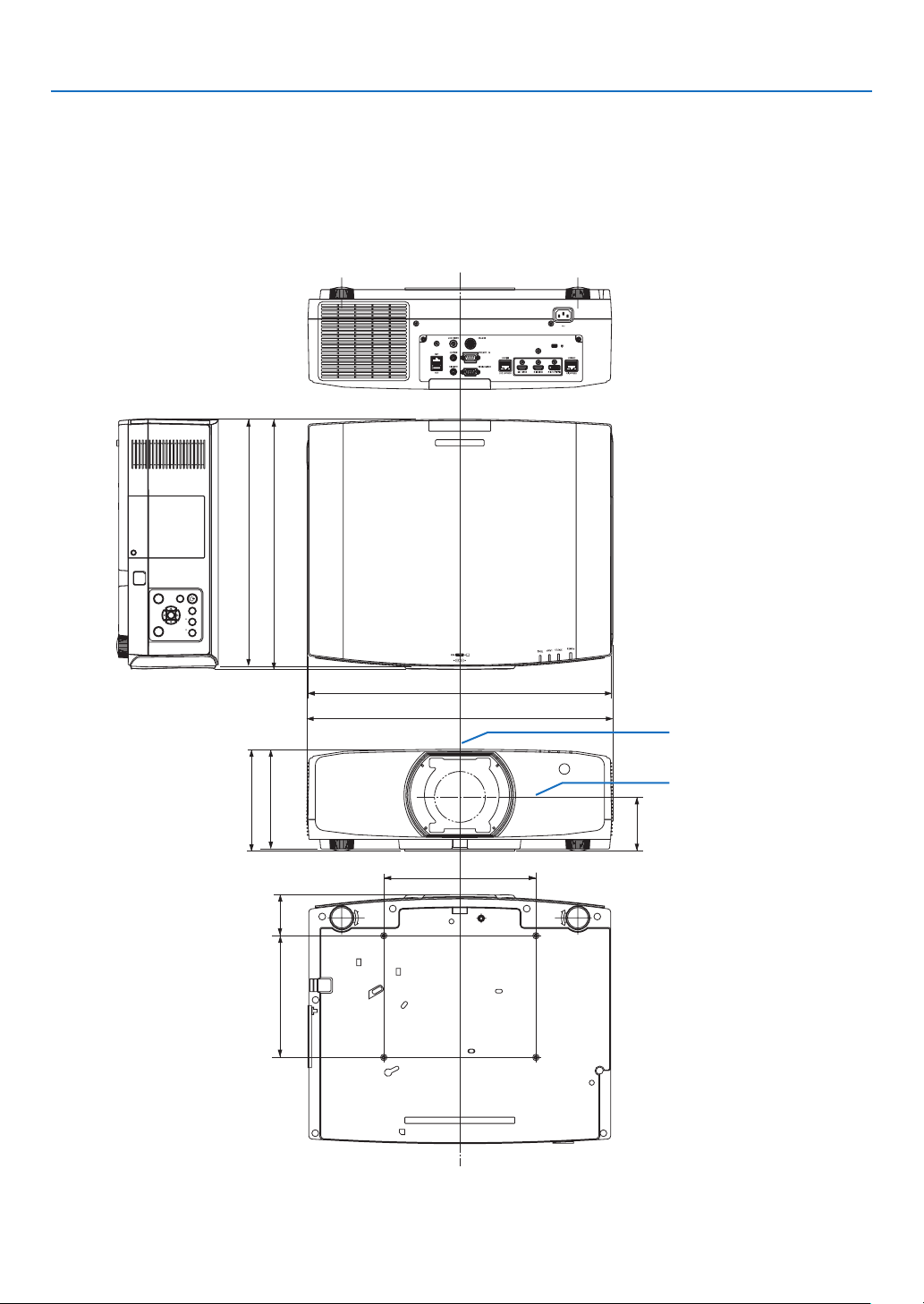
175
8. Appendix
90 (3.5)
499 (19.6)
250 (9.8)
200 (7.9)
68 (2.7)
411 (16.2)
164 (6.4)
168 (6.6)
503 (19.8)
406 (16.0)
INPUT
MENU
FOCUSSHIFT
EXIT
ZOOM
ENTER
L-CALIB.
HOME
POSITION
❹ Cabinet Dimensions
Lens center
Lens center
Unit:mm(inch)
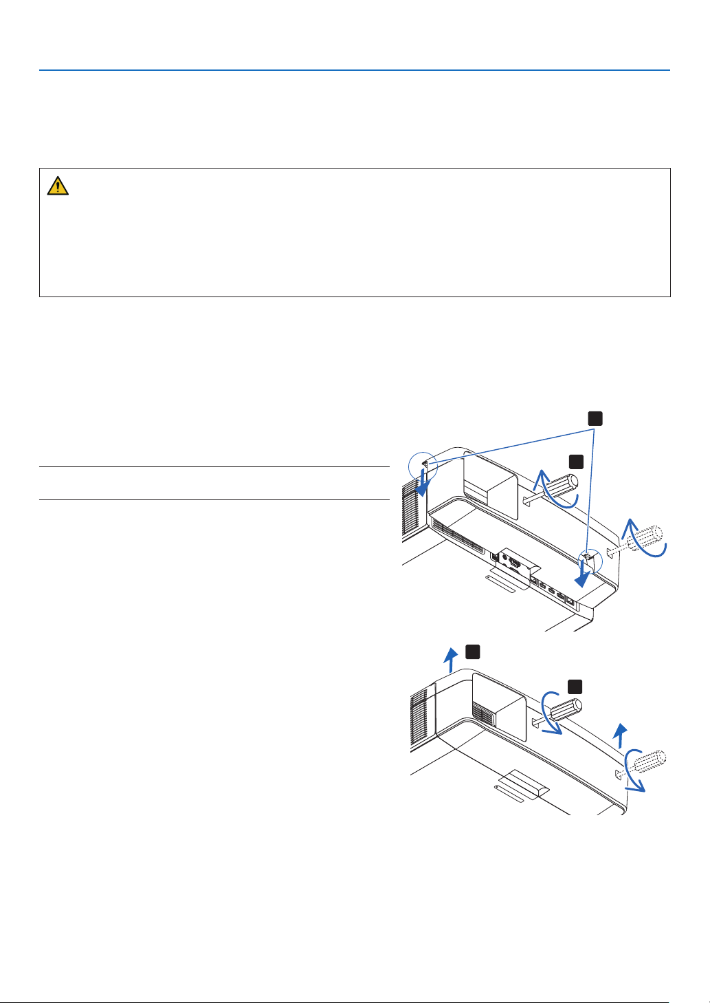
176
8. Appendix
❺ Mounting the cable cover (sold separately)
Mountingtheseparatelysoldcablecover(NP10CV)ontheprojectorallowsyouhidethecablesforacleaner
appearance.
CAUTION
• Aftermountingthecablecover,besuretofastenusingthescrewsprovided.Ifnot,thecablecovercouldfall
anddamagethecablecoverandpossiblyresultingininjury.
• Donotbundlethepowercordandplaceitunderthecablecover.Doingsocouldleadtore.
• Donotholdthecablecoverwhilemovingtheprojectoranddonotapplyexcessiveforcetothecablecover.
Doingsocoulddamagethecablecover,resultingintheprojectorfallingorcausinginjury.
Mounting
Preparations:
1. Connect the power cord and cables to the projector (the connection cords are omitted from the diagrams).
2. Prepare a Phillips screwdriver.
1. Insertthetworoundprotrusionsontheleftandrightedges
ofthecablecoverintothegroovesinthebottomofthe
projector to line it up.
NOTE:Becarefulnottoletthepowercordandcablesgetpinchedbythe
cable cover.
2. Turnthecablecoverscrewclockwise.
• Tightenthescrewsecurely.
2
1
Removing
1. Turnthecablecoverscrewcounterclockwiseuntilitturns
loosely.
• Hold the cable cover while doing this to prevent it from
falling.
• Thescrewdoesnotcomecompletelyoff.
2. Removethecablecover.
• Turnthecablecoveralittle,thenliftitoff.
1
2
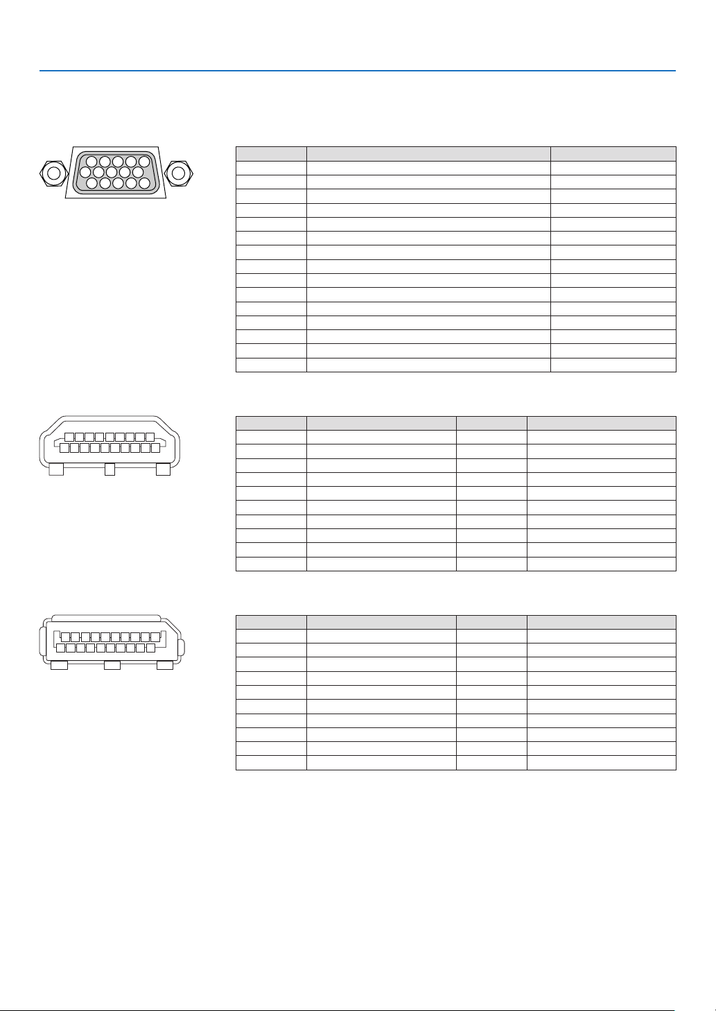
177
8. Appendix
❻ Pin assignments and signal names of main connectors
COMPUTER IN/ Component Input Connector (Mini D-Sub 15 Pin)
Connection and signal level of each pin
51423
10
11 12 13 14 15
6978
Signal Level
Videosignal:0.7Vp-p(Analog)
Syncsignal:TTLlevel
Pin No. RGBSignal(Analog) YCbCr Signal
1 Red Cr
2
GreenorSynconGreen Y
3 Blue Cb
4 Ground
5 Ground
6
RedGround CrGround
7 GreenGround YGround
8 BlueGround CbGround
9 NoConnection
10 SyncSignalGround
11 NoConnection
12 Bi-directionalDATA(SDA)
13 HorizontalSyncorCompositeSync
14 VerticalSync
15 DataClock
HDMI 1 IN/HDMI 2 IN Connector (Type A)
135791113151719
246810 12 14 16 18
Pin No. Signal Pin No. Signal
1
TMDSData2+ 11 TMDSClockShield
2 TMDSData2Shield 12 TMDSClock−
3 TMDSData2− 13 CEC
4
TMDSData1+ 14 Disconnection
5
TMDSData1Shield 15 SCL
6
TMDSData1− 16 SDA
7
TMDSData0+ 17 DDC/CECgrounding
8 TMDSData0Shield 18 +5Vpowersupply
9 TMDSData0− 19 Hotplugdetection
10 TMDSClock+
DisplayPort IN Connector
135791113151719
246810 12 14 16 18 20
Pin No. Signal Pin No. Signal
1
Mainlinklane3− 11 Grounding0
2 Grounding3 12 Mainlinklane0+
3 Mainlinklane3+ 13 Conguration1
4 Mainlinklane2− 14 Conguration2
5 Grounding2 15 Supplementarychannel+
6 Mainlinklane2+ 16 Grounding4
7 Mainlinklane1− 17 Supplementarychannel−
8 Grounding1 18 Hotplugdetection
9 Mainlinklane1+ 19 Return
10
Mainlinklane0− 20 +3.3Vpowersupply
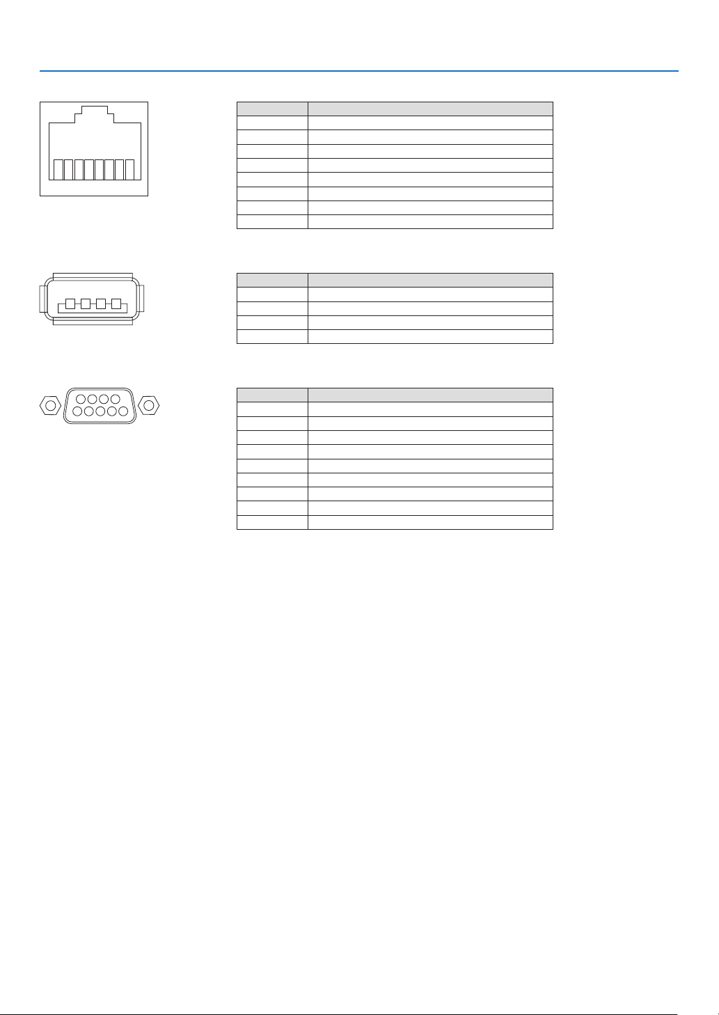
178
8. Appendix
HDBaseT IN/Ethernet Port (RJ-45)
12345678
Pin No. Signal
1 TxD+/HDBT0+
2 TxD−/HDBT0−
3 RxD+/HDBT1+
4 Disconnection/HDBT2+
5 Disconnection/HDBT2−
6 RxD−/HDBT1−
7 Disconnection/HDBT3+
8 Disconnection/HDBT3−
USB-A Port (Type A)
1
3
24
Pin No. Signal
1 V
BUS
2 D−
3 D+
4 Grounding
PC CONTROL Port (D-Sub 9 Pin)
1234
5
6789
Pin No. Signal
1 Unused
2
RxD receptiondata
3 TxD transmissiondata
4 Unused
5 Grounding
6 Unused
7
RTS transmissionrequest
8 CTS transmissionallowed
9 Unused
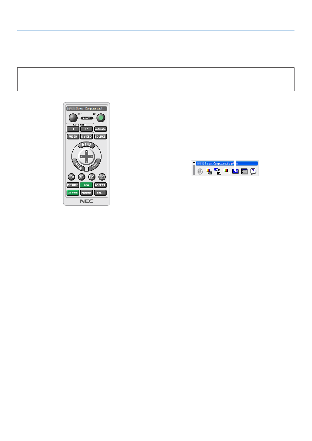
179
8. Appendix
❼ Changing the Background Logo (Virtual Remote Tool)
Thiswillhelpyouperformoperationssuchasprojector’spoweronoroffandsignalselectionviaaLANconnection.
Itisalsousedtosendanimagetotheprojectorandregisteritasthelogodataoftheprojector.Afterregisteringit,
youcanlockthelogotopreventitfromchanging.
Control Functions
PowerOn/Off,signalselection,picturefreeze,picturemute,audiomute,Logotransfertotheprojector,andremote
controloperationonyourPC.
VirtualRemotescreen
Use this button for changing
the background logo.
RemoteControlWindow Toolbar
ForgettingtheVirtualRemoteTool,pleasevisitourwebsiteanddownloadit:
http://www.nec-display.com/dl/en/index.html
NOTE:
• RemoteControlWindowisnotavailableforchangingthebackgroundlogo.
PleaseseetheHELPmenuoftheVirtualRemoteToolabouthowtodisplaytheToolbar.
• Logodata(graphics)thatcanbesenttotheprojectorwithVirtualRemoteToolhasthefollowingrestrictions:
(OnlyviaserialorLANconnection)
* Filesize:Within256kilobytes
* Imagesize:Withintheresolutionoftheprojector
* Fileformat:PNG(Fullcolor)
• Logodata(image)sentusingtheVirtualRemoteToolwillbedisplayedinthecenterwiththesurroundingareainblack.
• Toputthedefault“NEClogo”backinthebackgroundlogo,youneedtoregisteritasthebackgroundlogobyusingtheimagele
(NP-PA803U/NP-PA723U/NP-PA653U:¥Logo¥necpj_bbwux.png,NP-PA853W/NP-PA703W:¥Logo¥necpj_bbwx.png,NP-PA903X:
¥Logo¥necpj_bb_x.png)includedonthesuppliedNECProjectorCD-ROM.
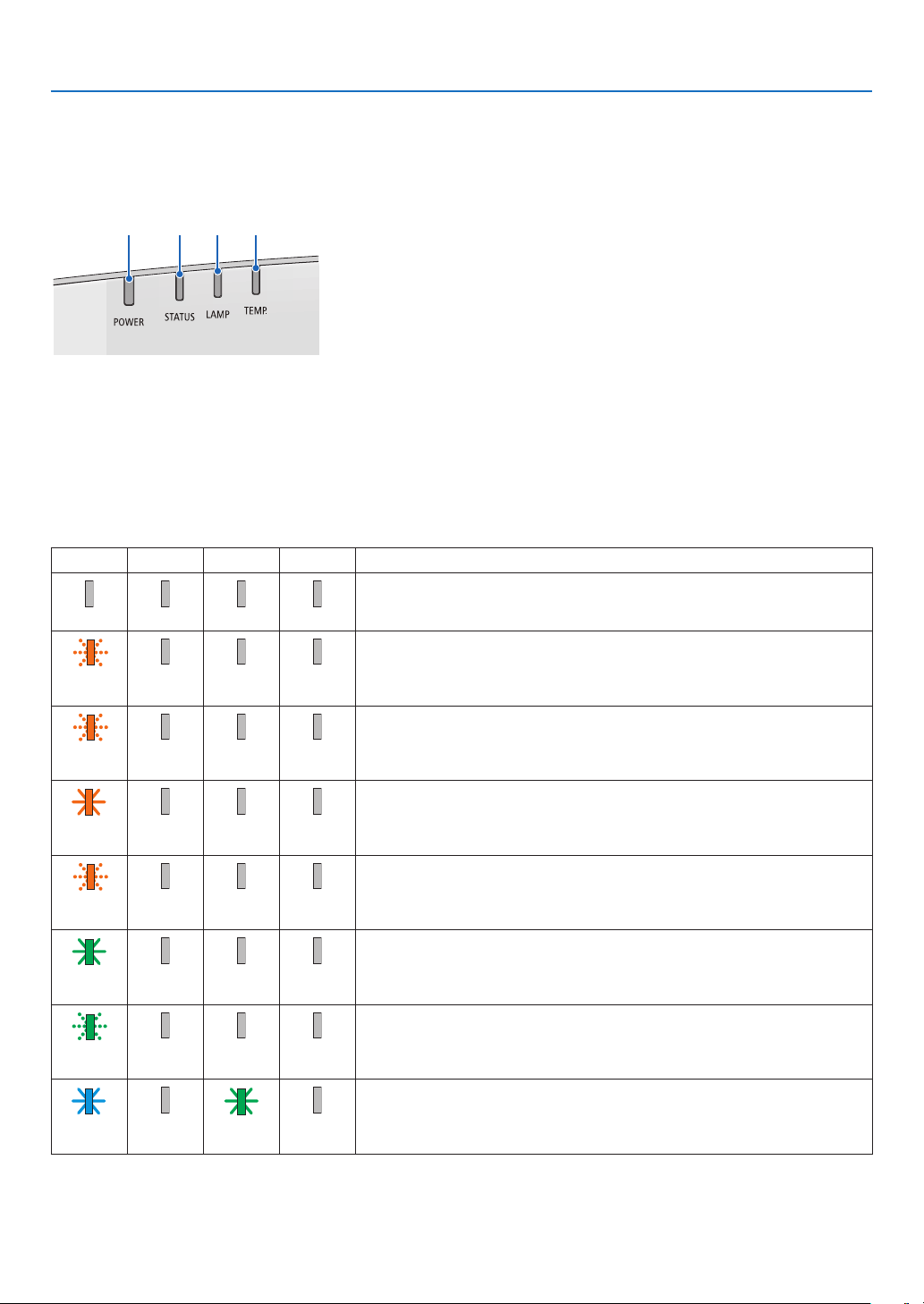
180
8. Appendix
❽ Troubleshooting
Thissectionhelpsyouresolveproblemsyoumayencounterwhilesettinguporusingtheprojector.
Feature of each indicator
②③④①
① POWERindicator
Thisindicatorinformsthepowerstatusoftheprojector.
② STATUSindicator
Thisindicatorlights/blinkswhenabuttonispressedwhiletheCONTROL
PANELLOCKfunctionisutilized,orwhileperformingthelenscalibration
andspecicoperations.
③ LAMPindicator
Thisindicatorinformsthestateoflamp,usagetimeofthelamp,andthe
statusofECOMODE.
④ TEMP.indicator
Thisisthetemperatureindicatorinformingtemperaturetroublewhenthe
ambienttemperatureistoohigh/low.
Indicator Message (Status message)
POWER STATUS LAMP TEMP. Projector status
Power is off
Off Off Off Off
InthestateofStandby(StandbymodeisNORMALandthenetworkisready.
Orange
(Blink*
1
)
Off Off Off
InthestateofStandby(StandbymodeisNORMALandthenetworkisunavail-
able.
Orange
(Blink*
2
)
Off Off Off
InthestateofStandby(StandbymodeisNORMALandthenetworkisavail-
able)
Orange
(Light)
Off Off Off
ONtimeastheprogramtimerisactivated.(InthestateofStandby)
Orange
(Blink*
3
)
Off Off Off
InthestateofSleep
Green
(Light)
Off Off Off
ONtimeastheprogramtimerisactivated.(InthestateofSleep)
Green
(Blink*
3
)
Off Off Off
Poweredstate(ECOmodeisOFF)
Blue
(Light)
Off Green
(Light)
Off
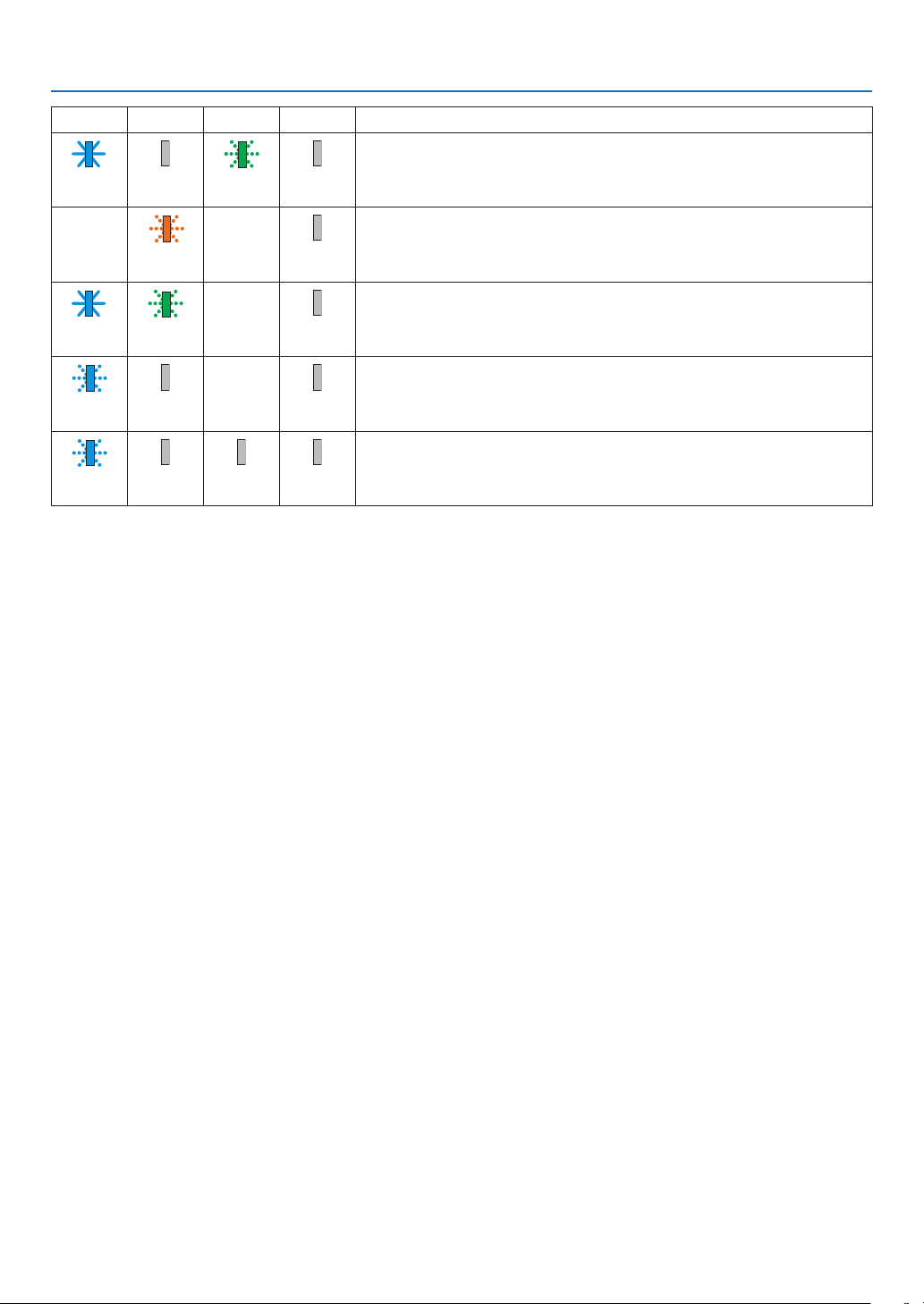
181
8. Appendix
POWER STATUS LAMP TEMP. Projector status
Poweredstate(ECOmodeisON)
Blue
(Light)
Off Green
(Blink*
3
)
Off
Lenscalibrationimplementrequest.
Status
varies
Orange
(Blink*
4
)
Status
varies
Off
Performingthelenscalibration
Blue
(Light)
Green
(Blink*
4
)
Status
varies
Off
OFFTimerisactivated,OFFtimeastheproogramtimerisactivated(Powered
state)
Blue
(Blink*
3
)
Off Status
varies
Off
PreparingforpoweringON
Blue
(Blink*
5
)
Off Off Off
*1 Repetitiontolightonfor1.5seconds/offfor1.5seconds
*2 Repetitiontolightonfor1.5seconds/offfor7.5seconds
*3 Repetitiontolightonfor2.5seconds/offfor0.5seconds
*4 Repetitiontolightonfor0.5seconds/offfor0.5seconds/onfor0.5seconds/offfor2.5seconds
*5 Repetitiontolightonfor0.5seconds/offfor0.5seconds
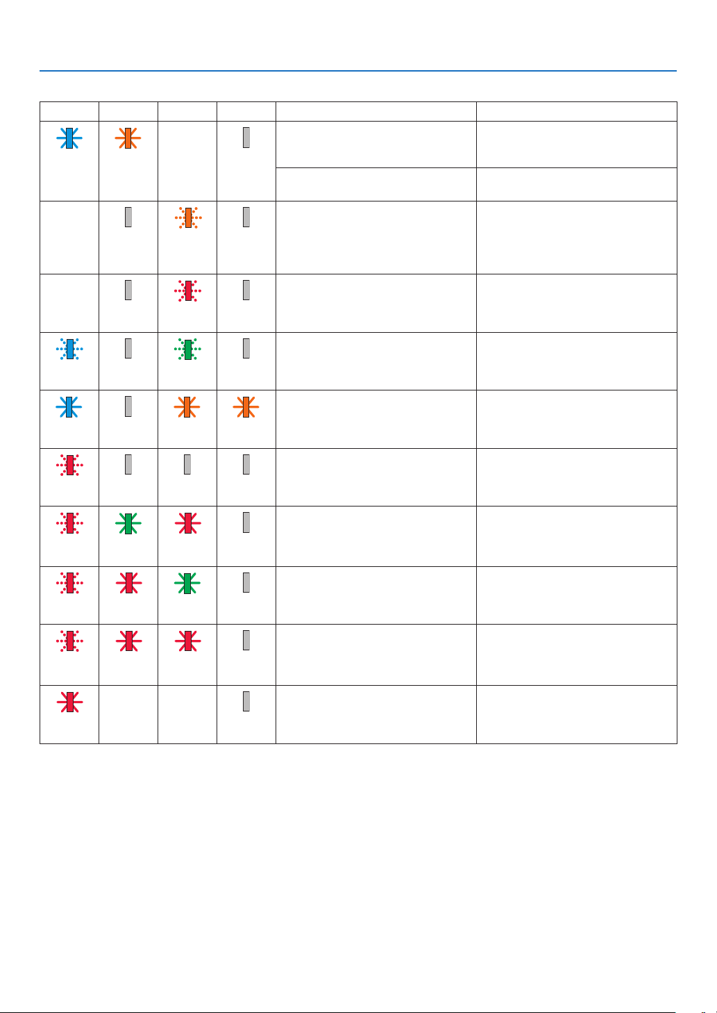
182
8. Appendix
Indicator Message (Error message)
POWER STATUS LAMP TEMP. Projector status Procedure
Abuttonhasbeenpressedwhilethe
KEYLOCKisactivated.
The projector's keys are locked. The
settingmustbecanceledtooperatethe
projector. (→page122)
Blue
(Light)
Orange
(Light)
Status
varies
Off
IDnumbersfortheprojectorandthe
remote control do not match.
CheckthecontrolIDs(→page123)
Lampreplacementgraceperiod. Thelamphasreachedtheendofitsser-
vice life and is now in the replacement
graceperiod(100hours).Replacethe
lamp to new one as soon as possible.
(→page156)
Status
varies
Off Orange
(Blink*
5
)
Off
Lampreplacementtimeexceeded. Thelamphasexceededitsreplacement
time.Replacethelampimmediately.
Status
varies
Off Red
(Blink*
5
)
Off
Preparingtorelightlampafterlighting
has failed.
Waitawhile.
Blue
(Blink*
5
)
Off Green
(Blink*
5
)
Off
Temperatureproblem(IntheForced
ECO)
Ambienttemtepratureishigh.Lowerthe
room temperature.
Blue
(Light)
Off Orange
(Light)
Orange
(Light)
Temperatureproblem Ambient temperature is out of the
operation temperature. Check if any
obstructionstaysneartheexhaustvent.
Red
(Blink*
5
)
Off Off Off
Lampdoesnotlight. Waitatleast1minute,themturnonthe
power back on. if the lamp still does
notlight,contactyourdelaerorservice
personnel.
Red
(Blink*
5
)
Green
(Light)
Red
(Light)
Off
Lampcoverproblem Lamp cover is not mounted properly.
Mount it properly. (→seepage158).
Red
(Blink*
5
)
Red
(Light)
Green
(Light)
Off
Lensproblem Thelensisnotmountedproperly,orthe
non-supportedlensismounted.Make
sure that the lens is supported, and
mount it correctly. (→seepage141).
Red
(Blink*
5
)
Red
(Light)
Red
(Light)
Off
Errorrequiringservicesupport Contactyourdealerorserviceperson-
nel. Make sure to check and inform
indicatorstatusforaskingtorepair.
Red
(Light)
Status
varies
Status
varies
Off
*1 Repetitiontolightonfor1.5seconds/offfor1.5seconds
*2 Repetitiontolightonfor1.5seconds/offfor7.5seconds
*3 Repetitiontolightonfor2.5seconds/offfor0.5seconds
*4 Repetitiontolightonfor0.5seconds/offfor0.5seconds/onfor0.5seconds/offfor2.5seconds
*5 Repetitiontolightonfor0.5seconds/offfor0.5seconds
• Whenthethermalprotectorisactivated:
Wheninsidetemperatureoftheprojectorbecomestoohighorlow,thePOWERindicatorstarttoredblinkina
shortcycle.Afterthishappened,thethermalprotectorwillactivateandtheprojectormaybeturnedoff.
Inthiscase,pleasetakethebelowmeasures:
- Pulloutthepowerplugfromthewallinlet.
- Placetheprojectorincoolplaceifithasbeenplacedinhighambienttemperature.
- Cleantheexhaustventifdusthasaccumulatedon.
- Leavetheprojectorforaboutonehouruntilinsidetemperaturegetslower.
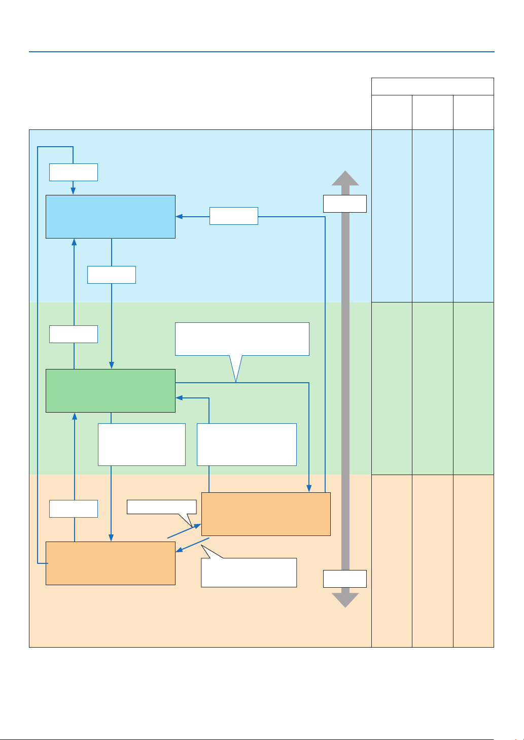
183
8. Appendix
Explanation on the POWER indicator and standby state
In the state the selected PROFILE for WIRED LAN is available.
Available ports in each state
(○: Available, ×: Unavailable)
HDBaseT IN/
Ethernet
HDBaseT
OUT/Ethernet
LAN PC CONTROL
○ ○ ○
○ ○ ○
× ○ ○
Indicator : Lights in blue
PoweredONstate
Indicator : Lights in green
Sleepstate
Indicator : Blinks in orange
Standbystate:Waitingtolinkwiththe
network
Indicator : Lights in orange
Standbystate:Thenetworkislinked.
Link-upnetwork
Link-down network for ap-
prox.10seconds
Power
consumption
High
Low
PowerOn
Inputsignal
Nooperation/Link-down
network/Nosignalinput
forapprox.10seconds
• Inputsignal
• Operationontheweb
browserviatheHTTP
server (→Seepage49)
Nooperation/Nocommunicationwith
thelink-upnetwork/Nosignalinputfor
approx.180seconds
PowerOff
PowerOn
PowerOn
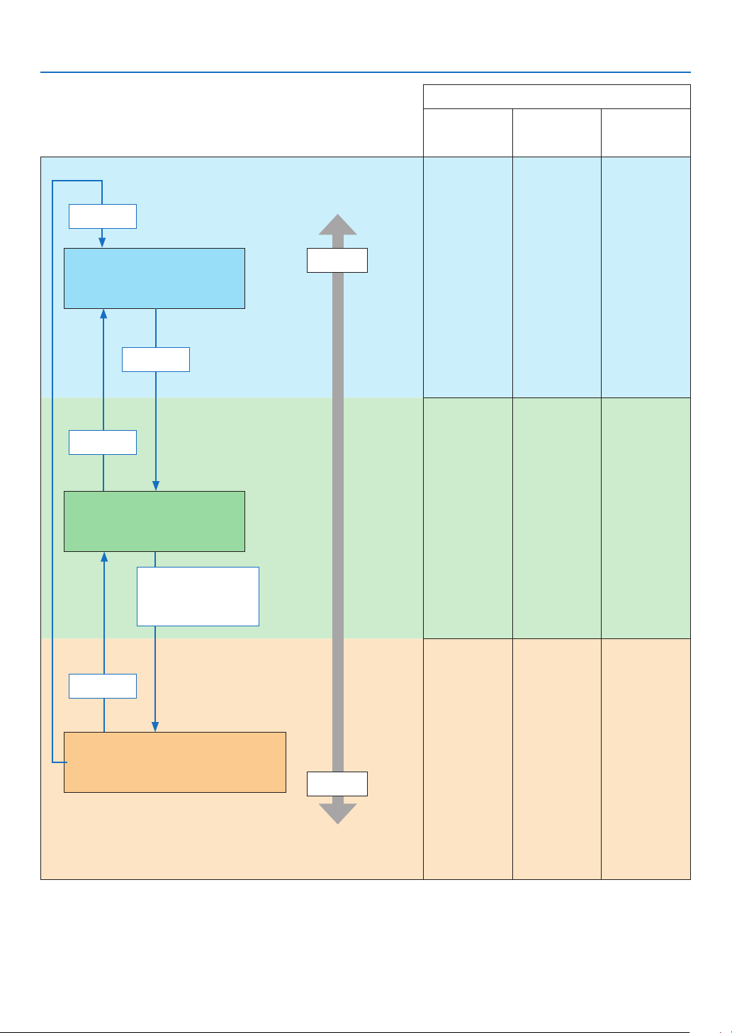
184
8. Appendix
In the state the selected PROFILE for WIRED LAN is
unavailable.
Available ports in each state
(○: Available, ×: Unavailable)
HDBaseT IN/Ethernet
HDBaseT OUT/
Ethernet
LAN PC CONTROL
○ × ○
○ × ○
× × ○
Indicator : Lights in blue
PoweredONstate
Indicator : Lights in green
Sleepstate
Indicator:Blinksinorange(withlonginterval)
Standbystate:Thenetworkisunavailable.
Power
consumption
High
Low
PowerOn
Inputsignal
Nooperation/Nosignal
inputforapprox.10
seconds
PowerOff
PowerOn

185
8. Appendix
Common Problems & Solutions
(→“Power/Status/LampIndicator”onpage180.)
Problem Check These Items
Does not turn on
or shut down
• Checkthatthepowercordispluggedinandthatthepowerbuttonontheprojectorcabinetortheremotecontrol
is on� (→ pages 15, 17)
• Ensurethatthelampcoverisinstalledcorrectly.(→ page 158)
• Checktoseeiftheprojectorhastemperatureerror,Ifprojectorinsidetemperatureistoohotorcool,itdisabledto
turn on the projector as the protection� Wait for a moment and try turn on the projector again�
• Thelampmayfailtolight.Waitafullminuteandthenturnonthepoweragain.
• Set[FANMODE]to[HIGHALTITUDE]whenusingtheprojectorataltitudesapproximately5500feet/1700meters
or higher� Using the projector at altitudes approximately 5500 feet/1700 meters or higher without setting to [HIGH
ALTITUDE] can cause the projector to overheat and the projector could shut down� If this happens, wait a couple
minutes and turn on the projector� (→ page 115)
If you turn on the projector immediately after the lamp is turned off, the fans run without displaying an image for
some time and then the projector will display the image� Wait for a moment�
Will turn off
• Ensurethatthe[OFFTIMER],[AUTOPOWEROFF]or[PROGRAMTIMER]isoff.(→ page 119, 133)
No picture
• Checkiftheappropriateinputisselected.(→ page 19) If there is still no picture, press the INPUT button or one of
the input buttons again�
• Ensureyourcablesareconnectedproperly.
• Usemenustoadjustthebrightnessandcontrast.(→ page 90)
• Ensurethatthelenscoverisopen.(→ page 17)
• Resetthesettingsoradjustmentstofactorypresetlevelsusingthe[RESET]intheMenu.(→ page 134)
• EnteryourregisteredkeywordiftheSecurityfunctionisenabled.(→ page 43)
• IftheHDMIinputortheDisplayPortsignalcannotbedisplayed,trythefollowing.
- Reinstall your driver for the graphics card built in your computer, or use the updated driver�
For reinstalling or updating your driver, refer to the user guide accompanied with your computer or graphics
card, or contact the support center for your computer manufacturer�
Install the updated driver or OS on your own responsibility�
We are not liable for any trouble and failure caused by this installation�
• ThesignalmaynotbesupporteddependingontheHDBaseTtransmissiondevice.Inaddition,RS232Cinterface
may not be supported�
• BesuretoconnecttheprojectorandnotebookPCwhiletheprojectorisinstandbymodeandbeforeturningonthe
power to the notebook PC�
In most cases the output signal from the notebook PC is not turned on unless connected to the projector before
being powered up�
* If the screen goes blank while using your remote control, it may be the result of the computer’s screen-saver or
power management software�
• Seealsothepage187�
Picture suddenly
becomes dark
• CheckiftheprojectorisintheForcedECOmodebecauseoftoohighambienttemperature.Ifthisisthecase,lower
the internal temperature of the projector by selecting [HIGH] for [FAN MODE]� (→ page 115)
Color tone or hue is
unusual
• Checkifanappropriatecolorisselectedin[WALLCOLOR].Ifso,selectanappropriateoption.(→ page 115)
• Adjust[HUE]in[PICTURE].(→ page 91)
Image isn’t square to
the screen
• Repositiontheprojectortoimproveitsangletothescreen.(→ page 21)
• Perform[GEOMETRICCORRECTION]whenthetrapezoidisdistorted.(→ page 103)
Picture is blurred
• Adjustthefocus.(→ page 23)
• Repositiontheprojectortoimproveitsangletothescreen.(→ page 21)
• Ensure that thedistance between theprojector and screenis within theadjustment range ofthe lens.
(→ page 162)
• Hasthelensbeenshiftedbyanamountexceedingtheguaranteedrange?(→ page 167)
• Condensationmayformonthelensiftheprojectoriscold,broughtintoawarmplaceandisthenturnedon.Should
this happen, let the projector stand until there is no condensation on the lens�
Flicker appears on
screen
• Set[FANMODE]tootherthan[HIGHALTITUDE]modewhenusingtheprojectorataltitudesapproximately5500
feet/1700 meters or lower� Using the projector at altitudes less than approximately 5500 feet/1700 meters and setting
to [HIGH ALTITUDE] can cause the lamp to overcool, causing the image to flicker� Switch [FAN MODE] to [AUTO]�
(→ page 115)
Image is scrolling
vertically, horizontally
or both
• Checkthecomputer’sresolutionandfrequency.Makesurethattheresolutionyouaretryingtodisplayissupported
by the projector� (→ page 169)
• AdjustthecomputerimagemanuallywiththeHorizontal/Verticalinthe[IMAGEOPTIONS].(→ page 92)
Remote control does
not work
• Installnewbatteries.(→ page 12)
• Makesuretherearenoobstaclesbetweenyouandtheprojector.
• Standwithin40m/1575inchoftheprojector.(→ page 13)
Indicator is lit or
blinking
• SeethePOWER/STATUS/LAMPIndicator.(→ page 180)


187
8. Appendix
If there is no picture, or the picture is not displayed correctly.
• PoweronprocessfortheprojectorandthePC.
BesuretoconnecttheprojectorandnotebookPCwhiletheprojectorisinstandbymodeandbeforeturningon
thepowertothenotebookPC.
InmostcasestheoutputsignalfromthenotebookPCisnotturnedonunlessconnectedtotheprojectorbefore
beingpoweredup.
NOTE:Youcancheckthehorizontalfrequencyofthecurrentsignalintheprojector’smenuunderInformation.Ifitreads“0kHz”,
this means there is no signal being output from the computer. (→ page 137 or go to next step)
• Enablingthecomputer’sexternaldisplay.
DisplayinganimageonthenotebookPC’sscreendoesnotnecessarilymeanitoutputsasignaltotheprojector.
WhenusingaPCcompatiblelaptop,acombinationoffunctionkeyswillenable/disabletheexternaldisplay.Usu-
ally,thecombinationofthe“Fn”keyalongwithoneofthe12functionkeysgetstheexternaldisplaytocomeon
oroff.Forexample,NEClaptopsuseFn+F3,whileDelllaptopsuseFn+F8keycombinationstotogglethrough
externaldisplayselections.
• Non-standardsignaloutputfromthecomputer
IftheoutputsignalfromanotebookPCisnotanindustrystandard,theprojectedimagemaynotbedisplayed
correctly.Shouldthishappen,deactivatethenotebookPC’sLCDscreenwhentheprojectordisplayisinuse.Each
notebookPChasadifferentwayofdeactivate/reactivatethelocalLCDscreensasdescribedinthepreviousstep.
Refertoyourcomputer’sdocumentationfordetailedinformation.
• ImagedisplayedisincorrectwhenusingaMac
WhenusingaMacwiththeprojector,settheDIPswitchoftheMacadapter(notsuppliedwiththeprojector)ac-
cordingtoyourresolution.Aftersetting,restartyourMacforthechangestotakeaffect.
ForsettingdisplaymodesotherthanthosesupportedbyyourMacandtheprojector,changingtheDIPswitchon
aMacadaptermaybounceanimageslightlyormaydisplaynothing.Shouldthishappen,settheDIPswitchto
the13"xedmodeandthenrestartyourMac.Afterthat,restoretheDIPswitchestoadisplayablemodeandthen
restarttheMacagain.
NOTE:AVideoAdaptercablemanufacturedbyAppleComputerisneededforaMacBookwhichdoesnothaveaminiD-Sub
15-pin connector.
• MirroringonaMacBook
* WhenusingtheprojectorwithaMacBook,outputmaynotbesetto1024×768unless“mirroring”isoffonyour
MacBook.Refertoowner’smanualsuppliedwithyourMaccomputerformirroring.
• FoldersoriconsarehiddenontheMacscreen
Foldersoriconsmaynotbeseenonthescreen.Shouldthishappen,select[View]→[Arrange]fromtheApple
menuandarrangeicons.
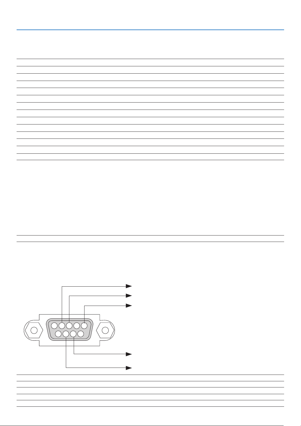
188
8. Appendix
❾ PC Control Codes and Cable Connection
PC Control Codes
Function Code Data
POWER ON 02H 00H 00H 00H 00H 02H
POWER OFF 02H 01H 00H 00H 00H 03H
INPUT SELECT HDMI1 02H 03H 00H 00H 02H 01H A1H A9H
INPUT SELECT HDMI2 02H 03H 00H 00H 02H 01H A2H AAH
INPUT SELECT DisplayPort 02H 03H 00H 00H 02H 01H A6H AEH
INPUT SELECT COMPUTER 02H 03H 00H 00H 02H 01H 01H 09H
INPUT SELECT HDBaseT 02H 03H 00H 00H 02H 01H BFH C7H
PICTURE MUTE ON 02H 10H 00H 00H 00H 12H
PICTURE MUTE OFF 02H 11H 00H 00H 00H 13H
SOUND MUTE ON 02H 12H 00H 00H 00H 14H
SOUND MUTE OFF 02H 13H 00H 00H 00H 15H
NOTE:ContactyourlocaldealerforafulllistofthePCControlCodesifneeded.
Cable Connection
CommunicationProtocol
Baud rate �����������������������������������������115200/38400/19200/9600/4800 bps
Data length
��������������������������������������8 bits
Parity
�����������������������������������������������No parity
Stop bit
��������������������������������������������1 bit
X on/off
��������������������������������������������None
Communications procedure
�������������Full duplex
NOTE:Dependingontheequipment,alowerbaudratemayberecommendedforlongcableruns.
PC Control Port (D-SUB 9P)
NOTE 1: Pins 1, 4, 6 and 9 are no used.
NOTE2:Jumper“RequesttoSend”and“CleartoSend”togetheronbothendsofthecabletosimplifycableconnection.
NOTE3:Forlongcablerunsitisrecommendedtosetcommunicationspeedwithinprojectormenusto9600bps.
15243
67 98
To GND of PC
To RxD of PC
To TxD of PC
To RTS of PC
To CTS of PC

189
8. Appendix
ABOUT THE ASCII CONTROL COMMAND
ThisdevicesupportsthecommonASCIIControlCommandforcontrollingourprojectorandmonitor.
Please visit our web site for detailed information about the command.
http://www.nec-display.com/dl/en/pj_manual/lineup.html
HOWTOCONNECTWITHANEXTERNALDEVICE
Therearetwomethodstoconnecttheprojectorwithanexternaldevicesuchasacomputer.
① Connectionthrutheserialport.
Connectstheprojectortoacomputerbyaserialcable(acrosscable).
② Connectionvianetwork(LAN/HDBaseT)
ConnectstheprojectortoacomputerbyaLANcable.
ConcerningtothetypeofLANcable,pleaseasktoyournetworkadministrator.
CONNECTION INTERFACE
① Connectionthrutheserialport.
CommunicationProtocol
Item Information
Baudrate 115200/38400/19200/9600/4800bps
Datalength 8bits
Parity bit Noparity
Stopbit 1bit
Flowcontrol None
Communicationsprocedure Fullduplex
② Connectionvianetwork
CommunicationProtocol(ConnectionviaLAN)
Item Information
Communicationspeed Setautomatically(10/100Mbps)
Supportedstandard IEEE802.3(10BASE-T)
IEEE802.3u(100BASE-TX,Auto-Negotiation)
UsetheTCPportnumber7142fortransmittingandreceivingcommand.
CommunicationProtocol(ConnectionviaHDBaseT)
Item Information
Communicationspeed 100Mbps
Supportedstandard IEEE802.3u(100BASE-TX,Auto-Negotiation)
UsetheTCPportnumber7142fortransmittingandreceivingcommand.
PARAMETERSFORTHISDEVICE
Input command
Inputterminal Response Parameter
HDMI1 hdmi1
hdmi1orhdmi
HDMI2 hdmi2 hdmi2
DisplayPort displayport
displayportordisplayport1
COMPUTER computer Oneamongcomputer,computer1,vga,vga1,rgb,andrgb1
HDBaseT hdbaset hdbasetorhdbaset1

190
8. Appendix
Status command
Response ErrorStatus
error:cover Lampcovertrouble
error:temp Temperatureerror
error:fan Fantrouble
error:light Lightsourcetrouble
error:system Systemtrouble
warning:light Underthegraceperiodoflampreplacement
warning:lter Filterreplacement

191
8. Appendix
❿ Troubleshooting Check List
Beforecontactingyourdealerorservicepersonnel,checkthefollowinglisttobesurerepairsareneededalsoby
referringtothe“Troubleshooting”sectioninyouruser’smanual.Thischecklistbelowwillhelpussolveyourproblem
more efficiently.
* Printthispageandthenextpageforyourcheck.
Frequency of occurrence □ always □sometimes(Howoften?_____________________) □other(__________________)
Power
□
No power (POWER indicator does not light blue)� See also “Status
Indicator (STATUS)”�
□
Power cord’s plug is fully inserted into the wall outlet�
□
Lamp cover is installed correctly�
□
Lamp Hours Used (lamp operation hours) was cleared after
lamp replacement�
□
No power even though you press and hold the POWER button�
□
Shut down during operation�
□
Power cord’s plug is fully inserted into the wall outlet�
□
Lamp cover is installed correctly�
□
[AUTO POWER OFF] is turned off (only models with the [AUTO
POWER OFF] function)�
□
[OFF TIMER] is turned off (only models with the [OFF TIMER]
function)�
Video and Audio
□
No image is displayed from your PC or video equipment to the
projector�
□
Still no image even though you connect the projector to the PC
first, then start the PC�
□
Enabling your notebook PC’s signal output to the projector�
• Acombinationoffunctionkeyswillenable/disabletheexter-
naldisplay.Usually,thecombinationofthe“Fn”keyalong
with one of the 12 function keys turns the external display
on or off.
□
No image (blue or black background, no display)�
□
Still no image even though you press the AUTO ADJUST button�
□
Still no image even though you carry out [RESET] in the
projector’s menu�
□
Signal cable’s plug is fully inserted into the input connector
□
A message appears on the screen�
(_____________________________________________)
□
The source connected to the projector is active and available�
□
Still no image even though you adjust the brightness and/or
the contrast�
□
Input source’s resolution and frequency are supported by the
projector�
□
Image is too dark�
□
Remains unchanged even though you adjust the brightness
and/or the contrast�
□
Image is distorted�
□
Image appears to be trapezoidal (unchanged even though you
carry out the [KEYSTONE] adjustment)�
□
Parts of the image are lost�
□
Still unchanged even though you press the AUTO ADJUST
button�
□
Still unchanged even though you carry out [RESET] in the
projector’s menu�
□
Image is shifted in the vertical or horizontal direction�
□
Horizontal and vertical positions are correctly adjusted on a
computer signal�
□
Input source’s resolution and frequency are supported by the
projector�
□
Some pixels are lost�
□
Image is flickering�
□
Still unchanged even though you press the AUTO ADJUST
button�
□
Still unchanged even though you carry out [RESET] in the
projector’s menu�
□
Image shows flickering or color drift on a computer signal�
□
Still unchanged even though you change [FAN MODE] from
[HIGH ALTITUDE] to [AUTO]�
□
Image appears blurry or out of focus�
□
Still unchanged even though you checked the signal’s resolution
on PC and changed it to projector’s native resolution�
□
Still unchanged even though you adjusted the focus�
□
No sound�
□
Audio cable is correctly connected to the audio input of the
projector�
□
Still unchanged even though you adjusted the volume level�
□
AUDIO OUT is connected to your audio equipment (only models
with the AUDIO OUT connector)�
Other
□
Remote control does not work�
□
No obstacles between the sensor of the projector and the
remote control�
□
Projector is placed near a fluorescent light that can disturb the
infrared remote controls�
□
Batteries are new and are not reversed in installation�
□
Buttons on the projector cabinet do not work (only models with the
[CONTROL PANEL LOCK] function)
□
[CONTROL PANEL LOCK] is not turned on or is disabled in
the menu�
□
Still unchanged even though you press and hold the INPUT
button for a minimum of 10 seconds�
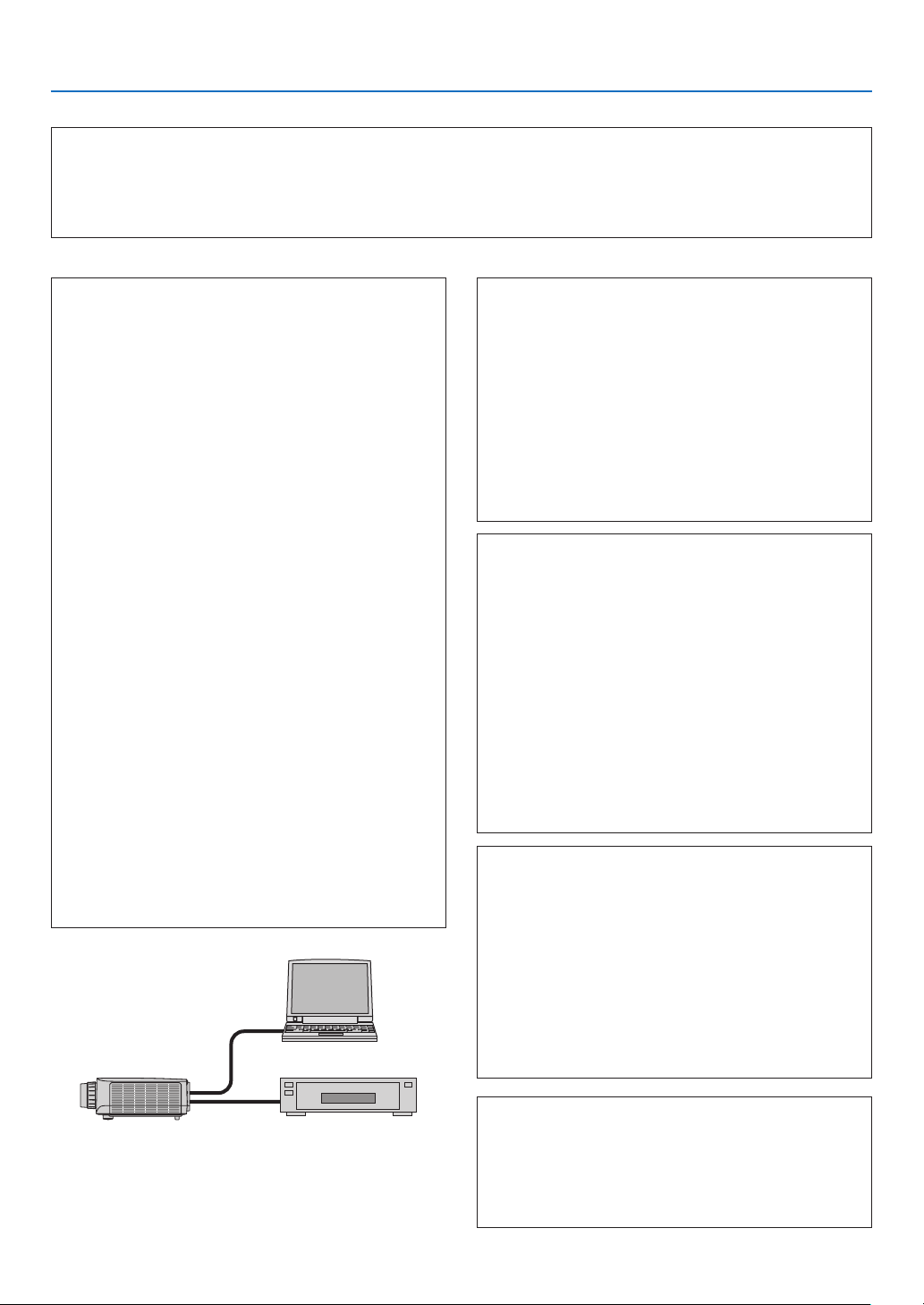
192
8. Appendix
In the space below please describe your problem in detail.
Information on application and environment where your projector is used
Projector
PC
Blu-ray player
Projector
Model number:
Serial No�:
Date of purchase:
Lamp operating time (hours):
Eco Mode: □ OFF □ ON
Information on input signal:
Horizontal synch frequency [ ] kHz
Vertical synch frequency [ ] Hz
Synch polarity H □ (+) □ (−)
V □ (+) □ (−)
Synch type □ Separate □ Composite
□ Sync on Green
Indicator Message:
□ POWER
Blinks in □ Blue □ Green □ Orange □ Red
[ ] cycles
Lights in □ Blue □ Green □ Orange □ Red
□ STATUS
Blinks in □ Blue □ Green □ Orange □ Red
[ ] cycles
Lights in □ Blue □ Green □ Orange □ Red
□ LAMP
Blinks in □ Blue □ Green □ Orange □ Red
[ ] cycles
Lights in □ Blue □ Green □ Orange □ Red
Remote control model number:
Installation environment
Screen size: inch
Screen type: □ White matte □ Beads □ Polarization
□ Wide angle □ High contrast
Throw distance: feet/inch/m
Orientation: □ Ceiling mount □ Desktop
Power outlet connection:
□
Connected directly to wall outlet
□ Connected to power cord extender or other (the
numberofconnectedequipment______________)
□ Connected to a power cord reel or other (the number
ofconnectedequipment______________)
Computer
Manufacturer:
Model number:
Notebook PC □ / Desktop □
Native resolution:
Refresh rate:
Video adapter:
Other:
Videoequipment
VCR, Blu-ray player, Video camera, Video game or other
Manufacturer:
Model number:
Signal cable
NECstandardorothermanufacturer’scable?
Model number: Length: inch/m
Distribution amplifier
Model number:
Switcher
Model number:
Adapter
Model number:

193
8. Appendix
⓫ REGISTER YOUR PROJECTOR! (for residents in the United
States, Canada, and Mexico)
Pleasetaketimetoregisteryournewprojector.ThiswillactivateyourlimitedpartsandlaborwarrantyandInstaCare
serviceprogram.
Visit our web site at www.necdisplay.com,clickonsupportcenter/registerproductandsubmityourcompletedform
online.
Uponreceipt,wewillsendaconrmationletterwithallthedetailsyouwillneedtotakeadvantageoffast,reliable
warrantyandserviceprogramsfromtheindustryleader,NECDisplaySolutionsofAmerica,Inc.

©NECDisplaySolutions,Ltd.2017 7N952552