22077 rev. M
INSTALLATION AND USER GUIDE FOR
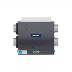
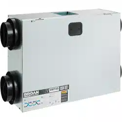
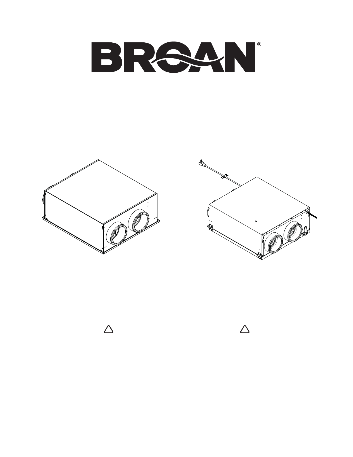
BROAN ERVS100S-HW AND ERVS100S-PC
RESIDENTIAL USE ONLY
0009
!
0009
!
VB0342
READ AND SAVE THESE INSTRUCTIONS
INSTALLER: LEAVE THIS MANUAL WITH HOMEOWNER
Broan-NuTone LLC, 926 west State Street, Hartford, Wisconsin, USA 800-558-1711 broan-nutone.com
REGISTER YOUR PRODUCT ONLINE AT: www.broan-nutone.com/register
For additional information - visit www.broan-nutone.com
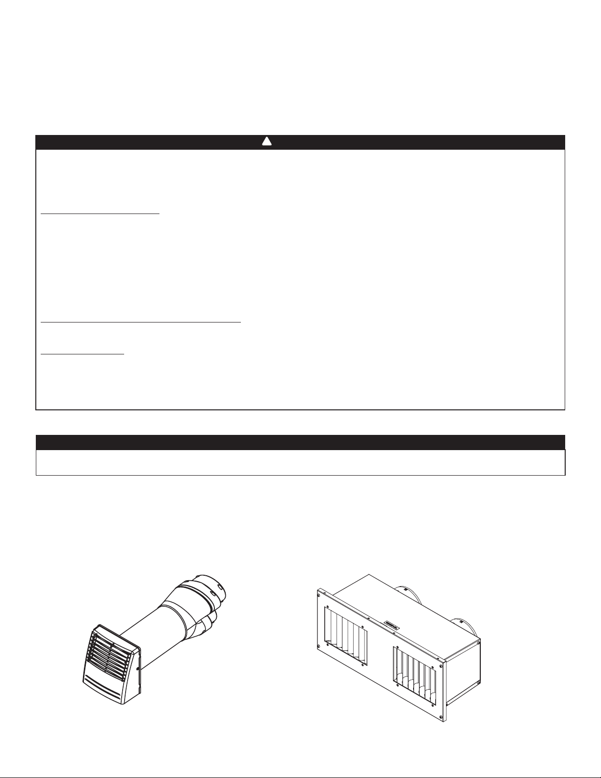
VB0347
ERVS100S-HW ERVS100S-PC
2
WARNING
0009
!
Please take note that this manual uses the following symbols to emphasize particular information:
NOTE: Indicates supplementary information needed to fully complete an instruction.
CAUTION
Identifies an instruction which, if not followed, may severely damage the unit and/or its components.
ABOUT THIS MANUAL
ABOUT THESE UNITS
LIMITATION
For residential (domestic) installation only. Installation work and electrical wiring must be done by a qualified person(s) in accordance with all applicable
codes and standards, including fire-rated construction codes and standards.
TO REDUCE THE RISK OF FIRE, ELECTRIC SHOCK, OR INJURY TO PERSON(S) OBSERVE THE FOLLOWING:
1. Use this unit only in the manner intended by the manufacturer. If you have questions, contact the manufacturer at the address or telephone number
listed in the warranty.
2. Before servicing or cleaning the unit, disconnect the power cord from electrical outlet or turn power off at the service panel.
3. This unit is not designed to provide combustion and/or dilution air for fuel-burning appliances.
4. When cutting or drilling into a wall or ceiling, do not damage electrical wiring and other hidden utilities.
5. Do not use this unit with any solid-state speed control device other than following controls:
6. This unit must be grounded. For the ERVS100S-PC unit only: The power supply cord has a 3-prong grounding plug for your personal safety. It must
be plugged into a mating 3-prong grounding receptacle, grounded in accordance with the national electrical code and local codes and ordinances.
Do not remove the ground prong. Do not use an extension cord.
7. Do not install in a cooking area or connect directly to any appliances.
8. Do not use to exhaust hazardous or explosive materials and vapors.
9. This unit must be protected from the elements.
10. When performing installation, servicing or cleaning these units, it is recommended to wear safety glasses and gloves.
11. When applicable local regulation comprises more restrictive installation and/or certification requirements, the aforementioned requirements prevail
on those of this document and the installer agrees to conform to these at his own expense.
CAUTION
1. Do not use your unit during construction or renovation of your house or when sanding drywall. Certain types of dust and vapors may damage your
system.
2. Please read specification label on product for further information and requirements.
3. Be sure to duct air outside – Do not intake/exhaust air into spaces within walls or ceiling or into attics, crawl spaces, or garage. Do not attempt to
recover the exhaust air from a dryer or a range hood.
4. Intended for residential installation only in accordance with the requirements of NFPA 90B (for a unit installed in U.S.A.).
5. Do not run any air ducts directly above or within 2 ft of a furnace or its supply plenum, boiler, or other heat producing appliance.
6. The ductwork is intended to be installed in compliance with all applicable local and national codes.
7. When leaving the house for a long period of time (more than two weeks), a responsible person should regularly check if the unit operates adequately.
8. If the ductwork passes through an unconditioned space (e.g.: attic), the unit must operate continuously except when performing maintenance and/or
repair. Also, the ambient temperature of the house should never drop below 65°F.
9. At least once a year, the unit mechanical and electronic parts should be inspected by qualified service personnel.
10. Make sure at all times that the outside intake and exhaust hoods are free from any snow during the winter season. It is important to check your unit
during a big snow storm, so it doesn't draw in any snow. If this is the case, please turn the unit OFF for a few hours.
11. Since the electronic control system of the unit uses a microprocessor, it may not operate correctly because of external noise or very short power failure.
If this happens, unplug the unit (or, if hard-wired, turn off power at service panel) and wait approximately 10 seconds. Then, plug the unit in again (or
restore power from service panel).
12. Do not make excessive use of fragrance appliances or chemicals since some may damage the unit components material.
13. For installation within a garage, make sure the unit door is always closed except during attended maintenance to reduce the likelihood of exhaust
fumes to be introduced within the home.
WARNING
Identifies an instruction which, if not followed, might cause serious personal injuries including possibility of death.
!
AUXILIARY CONTROLS ENERGIZED BY UNIT
BROAN VB20W 20-MINUTE LIGHTED PUSH-BUTTON TIMER
STANDARD DRY CONTACT STANDBY SWITCH
3
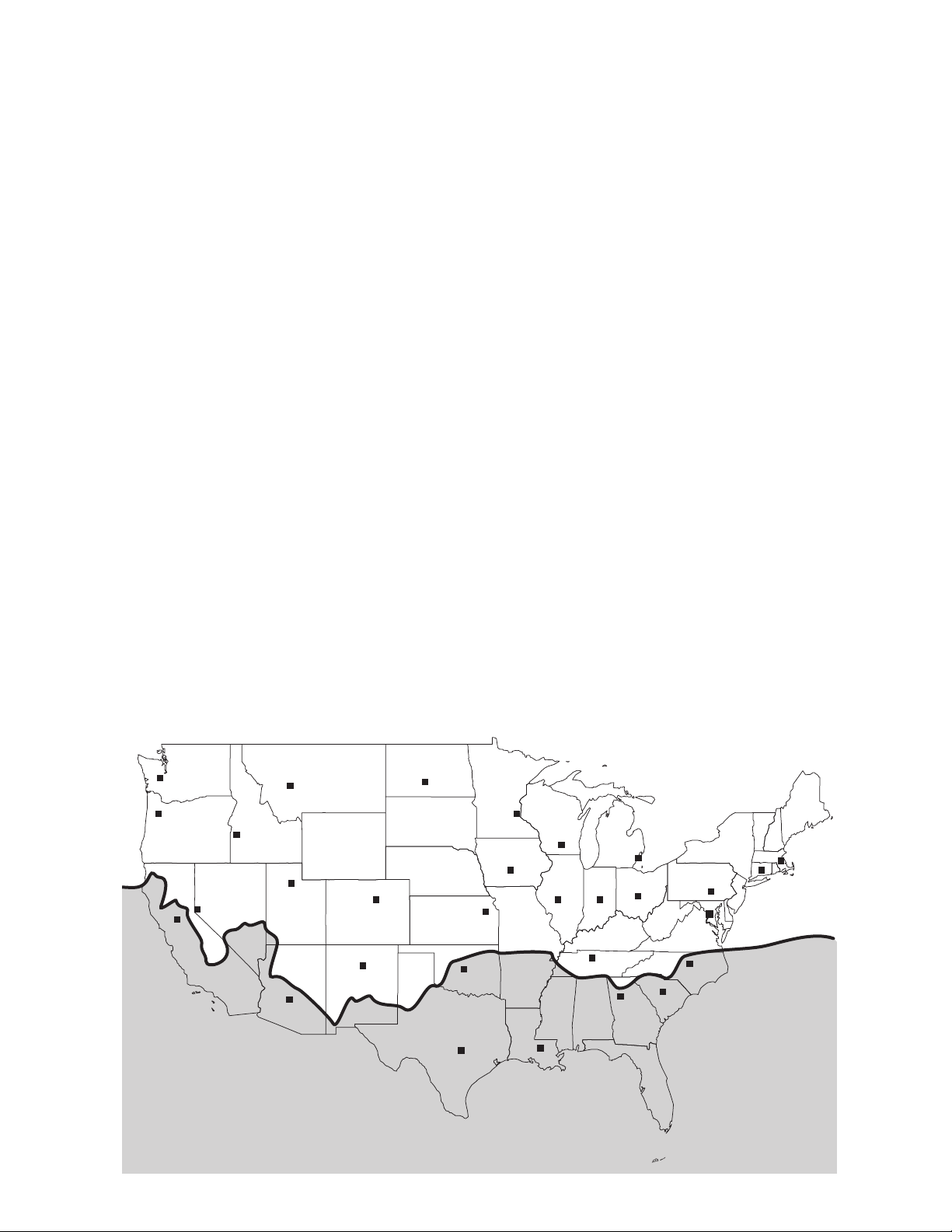
1 Safe Installation Zone
HELENA
OLYMPIA
SALEM
BOISE
BISMARCK
SALT LAKE CITY
ST. PA UL
DES MOINES
MADISON
HARRISBURG
SACRAMENTO
DENVER
TOPEKA
DETROIT
INDIANAPOLIS
SANTA FE
SPRINGFIELD
OKLAHOMA CITY
PHOENIX
COLUMBUS
NASHVILLE
ATLANTA
BATON ROUGE
AUSTIN
COLUMBIA
RALEIGH
WASHINGTON
HARTFORD
BOSTON
RENO
VN0010
A
B
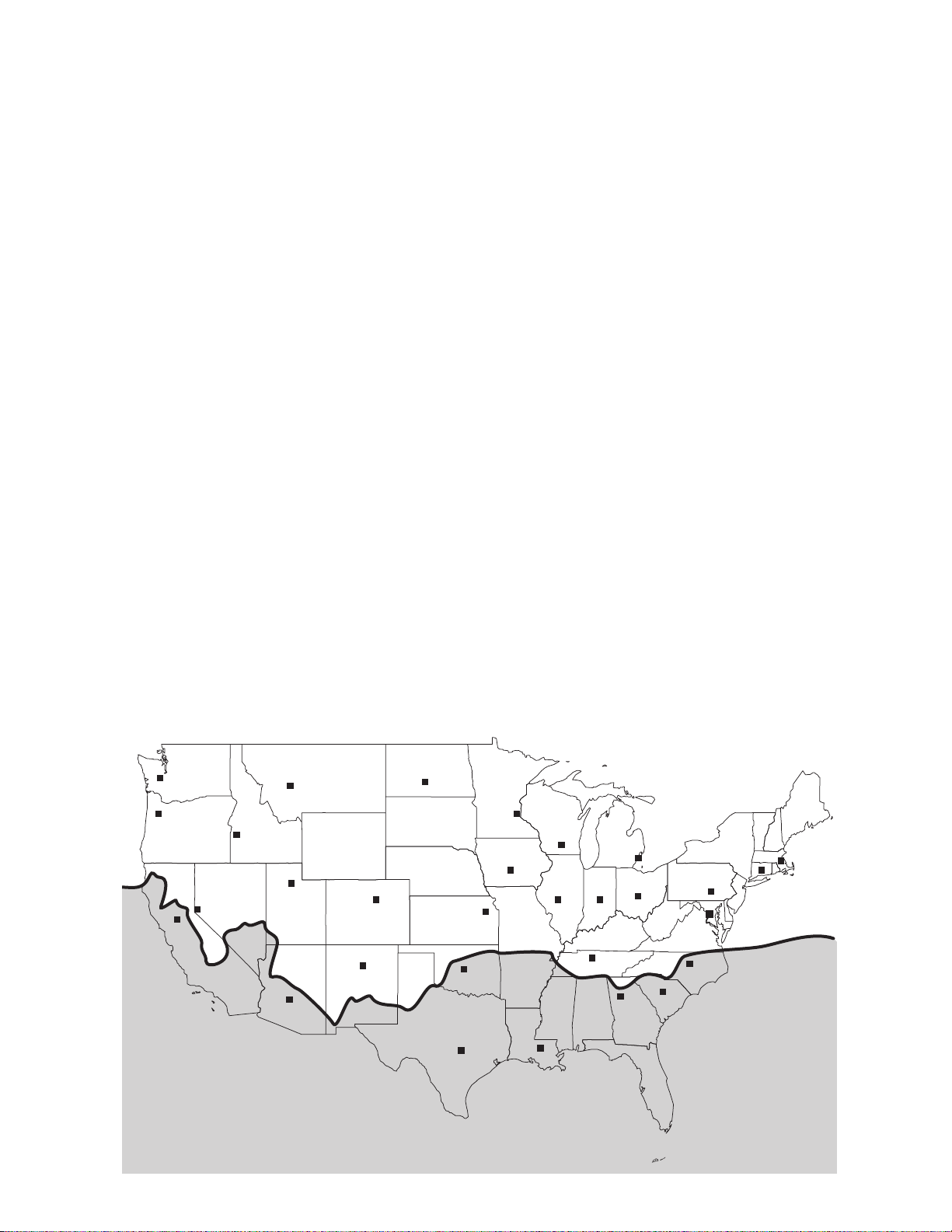
Installation requirements differ from zones A and B shown within map below, refer to sections 3.1 to 3.3.2 for specific details and
cautions for each installation type.
TABLE OF CONTENTS
1 Safe Installation Zone ................................................................................................3
2 Unit Preparation ........................................................................................................ 4
2.1 Choose an Appropriate Location for the Unit ........................................................................................ 4
2.2 Electrical Connection Type (Cord Connected or Hardwired) ................................................................. 4
3 Installation ............................................................................................................4-12
3.1 Positioning the Unit ............................................................................................................................. 4-6
3.2 Combining with an AHU ........................................................................................................................ 7
3.3 Installing the Registers, Ductwork and Hoods ..................................................................................... 8-9
3.4 Installing a Tandem
®
Transition* Kit ........................................................................................................ 9
3.5 Connecting the Controls ...................................................................................................................... 10
3.6 Connecting the Hardwire Connection (ERVS100S-HW unit only) .................................................... 11-12
4 Getting the Unit Started ..........................................................................................13
4.1 Unit Setttings ........................................................................................................................................ 13
4.2 Prepare the Unit .................................................................................................................................... 13
4.3 Booting Sequence ................................................................................................................................ 13
5 Maintenance .......................................................................................................14-15
5.1 Quarterly Maintenance ......................................................................................................................... 14
5.2 Annual Maintenance ............................................................................................................................. 15
6 Warranty .................................................................................................................. 15
7 Wiring Diagram .......................................................................................................16
8 Service Parts ............................................................................................................ 17
9 Troubleshooting ......................................................................................................18
4
2 Unit Preparation
• Inspect the exterior of the unit for shipping damage.
• Unit should never operate while the building is still in construction.
• ERVS100S-HW is shipped with door protection materials. Leave in place during construction process and remove after surrounding
ceiling has been finished.
2.1 Choose an Appropriate Location for the Unit
• Within an area of the house where the ambient temperature is kept between 50°F and 135°F;
• Away from living areas (dining room, living room, bedroom), if possible to reduce noise level;
• So as to provide easy access to the interior cabinet for maintenance;
• Close to an exterior wall, so as to limit the length of the insulated flexible ducts to and from the unit;
• Away from hot chimneys, electrical panel and other fire hazards;
• Within 28" of a power source (standard outlet, ERVS100S-PC unit only).
2.2 Electrical Connection Type (Plug Connected or Hardwired)
• According to your needs and applicable codes, make sure you have the appropriate model (ERVS100S-PC: plug connected unit
and ERVS100S-HW: hardwired unit).
3 Installation
3.1 Positioning the Unit
• Unit can be installed between 24” on-center trusses, on top of 24” on-center trusses in reversed position or under the ceiling,
using brackets. A set of 4 brackets is included in the hardware kit, along with the necessary screws.
• The unit shall be connected to a 15-amp electrical circuit. It is recommended to label the circuit to identify this system as the
Fresh Air System. If plug connected (ERVS100S-PC unit only), a standard 3-prong electrical outlet has to be available within
28” of the unit.
• Allow a 12” clearance for the door, core and filters to be removed for maintenance.
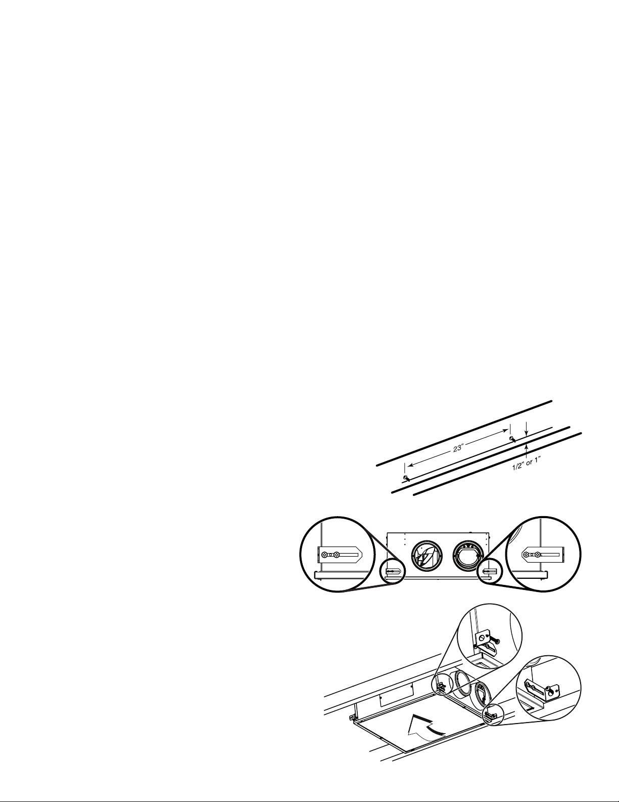
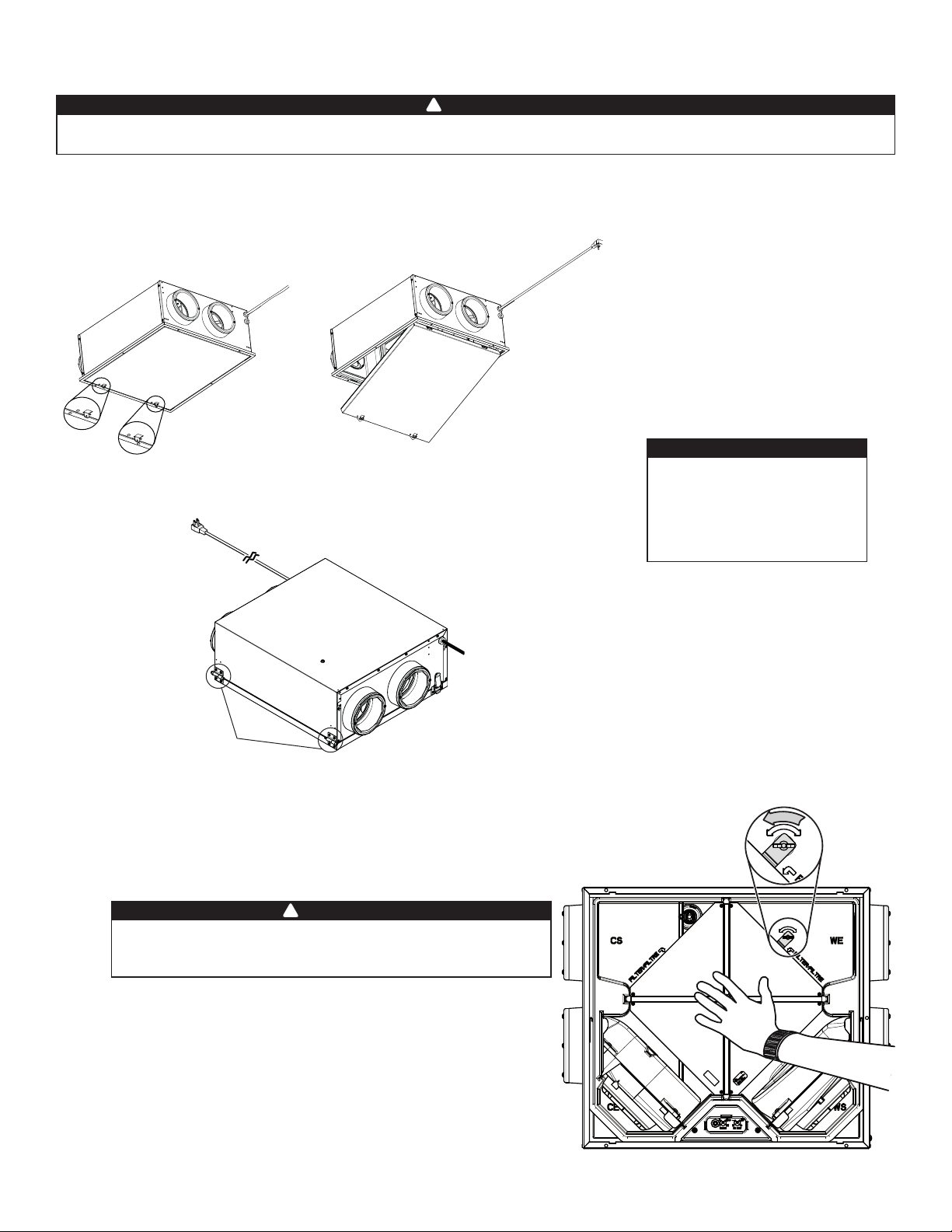
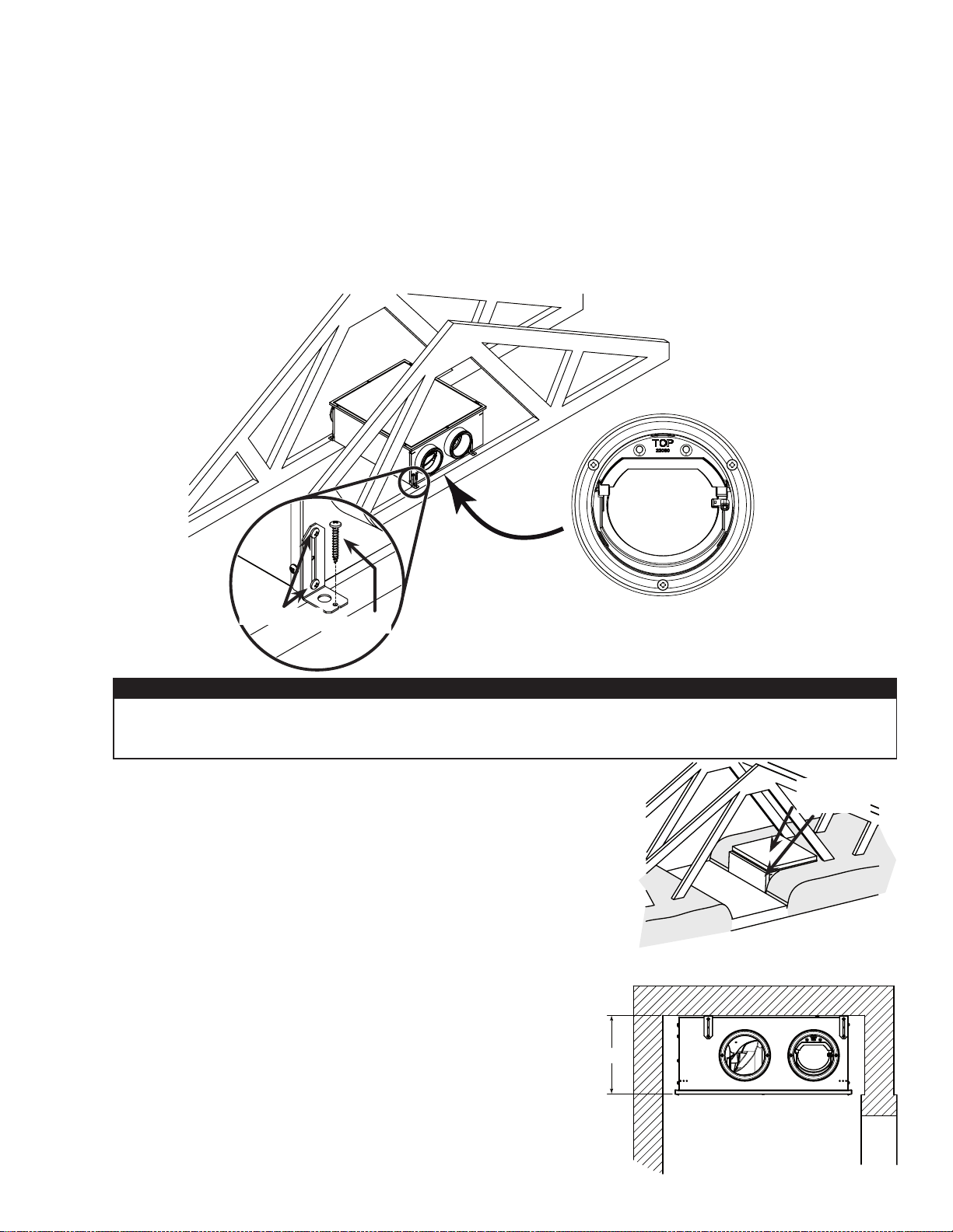
3.1.1 Installation in the ceiling (between 24” on-center trusses)
ERVS100S-HW only
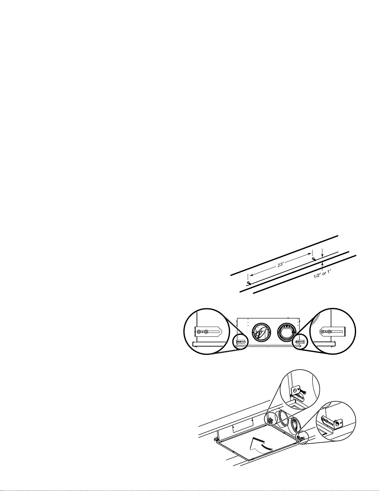
1. Trace a level line on both trusses, at 1/2” or 1” from the bottom, for
the unit bracket location (1/2” will allow the unit door perimeter to
lay on ceiling material while 1” will result in flush mount installation;
see A and B in next page). On one truss, screw half way on level line
two no. 8 x 1½” provided screws, leaving 23” between each other.
2. Mount the 4 brackets to the unit as illustrated at
right, using two no.10 x 5/8" screws provided for
each bracket.
TIP: Screw half way the screws to allow adjusment
between trusses, see insets at right (left shows the
minimum distance and right the maximum distance.
3. Hang the lightest side of the unit on the screws mounted
on the truss using the larger holes of the brackets.
4. Lift the other side of the unit and secure it to the other
truss using one no. 8 x 1½” screw per bracket, inserted
through the smaller hole of the brackets.
VD0391A
VD0394
VD0390
Unit must be installed in the horizontal orientation as shown in section 3.1.

5
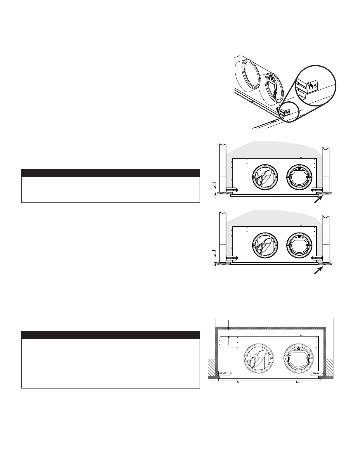
3.1.1 Installation in the ceiling (between 24” on-center trusses) (cont'd)
5. Secure the first brackets installed to the truss using one no. 8 x 1½” screw
per bracket, inserted through the smaller hole, then tighten completely the
brackets screws to the unit.
6. Spread the insulation over and around the unit.
3 Installation (cont'd)
3.1 Positioning the Unit (cont'd)
VD0393
VD0386
1/2”
1”
1
2
1/2" CEILING MATERIAL
1/2" CEILING MATERIAL
INSULATION
(OVER AND AROUND
THE UNIT)
INSULATION
(OVER AND AROUND
THE UNIT)
CAUTION
When installed in ceiling in the attic of a zone A, insulation must
be spread over the unit. Installed unit area ambient temperature
must be kept between 50°F and 135°F.
ZONE A
CAUTION
When installed in the ceiling in an unconditioned space
(e.g.: attic), above the unit in zone B, a sealed enclosure must
be installed over and around the unit to avoid air leakage,
condensation and mold growth risks. Insulation must be spread
over and around the enclosure. Ducting must pass through the
sealed enclosure and must be sealed to the enclosure.
ZONE B
7. Spread the insulation over and around the sealed enclosure.
VD0521
INSULATION
(OVER AND AROUND THE
SEALED ENCLOSURE)
DOOR FRAME COULD BE MOUNTED FLUSH TO CEILING MATERIAL
AS SHOWN IN OPTION 2 ABOVE.
A clearance of about 1" is needed
over the unit to ensure the unit does
not touch the enclosure
6
9¼”
VD0385
24"-DEEP CLOSET
3 Installation (cont'd)
3.1 Positioning the Unit (cont'd)
VH0111
DOOR
NO. 10 X 5/8"
NO. 8 X 1½"
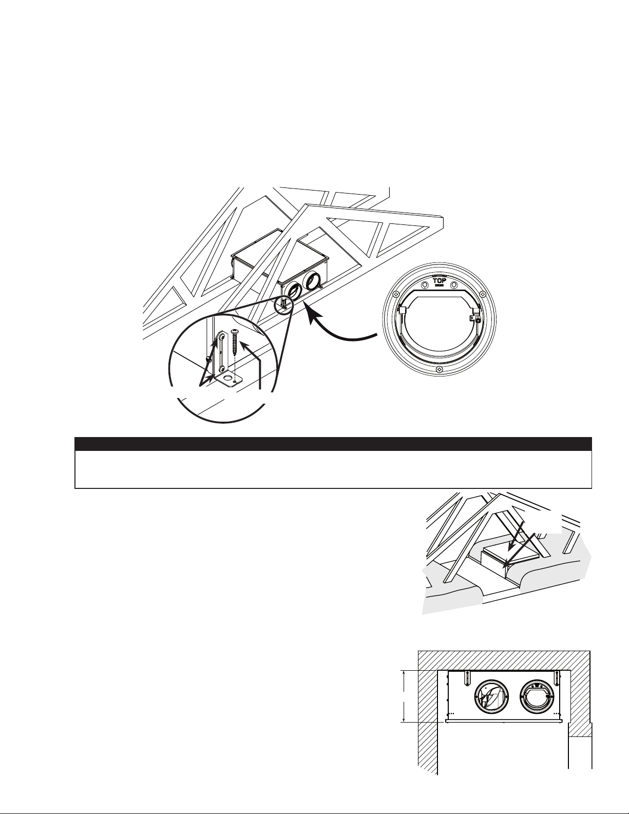
3.1.2 Zone A only - Installation in the attic over the insulation (unit having its door on top) ERVS100S-PC
and ERVS100S-HW
1. Rotate the backdraft damper 180° (no tool required) so that it falls in closed position and the word "TOP" engraved on the
damper is up once the unit is in place.
2. Mount the brackets to the unit as illustrated below using two no. 10 x 5/8" screws provided for each bracket.
3. Secure the unit to the trusses using one no. 8 x 1½" screw provided for each bracket.
4. IMPORTANT: For unvented attic and without radiant barrier sheathing, insulation material must be added around and over
the unit to prevent excess of heat in the unit. Ensure access is kept for product maintenance.
3.1.3 Installation under the ceiling (in a conditioned space)
1. Mount the brackets to the unit as illustrated above using two no. 10 x 5/8”
screws provided for each bracket.
2. Secure unit to the ceiling using two no. 8 x 1½” screws provided for each
bracket, making sure not to secure it into drywall alone.
KEEP 12" CLEARANCE UNDERNEATH THE
UNIT FOR MAINTENANCE
CAUTION
Installed unit area ambient temperature must be kept between 50°F and 135°F, insulation material must be
added over the unit if temperature in attic exceeds this limit in summer to protect electronic components
from exposure to high temperature.
Spread the insulation around the unit, then use an insulated ducting plate to cover
the unit door to maintain access inside the unit. Make sure to keep 12” clearance
above the unit to remove the door, the core and filters for maintenance purposes.
VH0116
DUCTING
PLATE
NOTE: Validate applicable codes.
ERVS100S-HW SHOWN
7
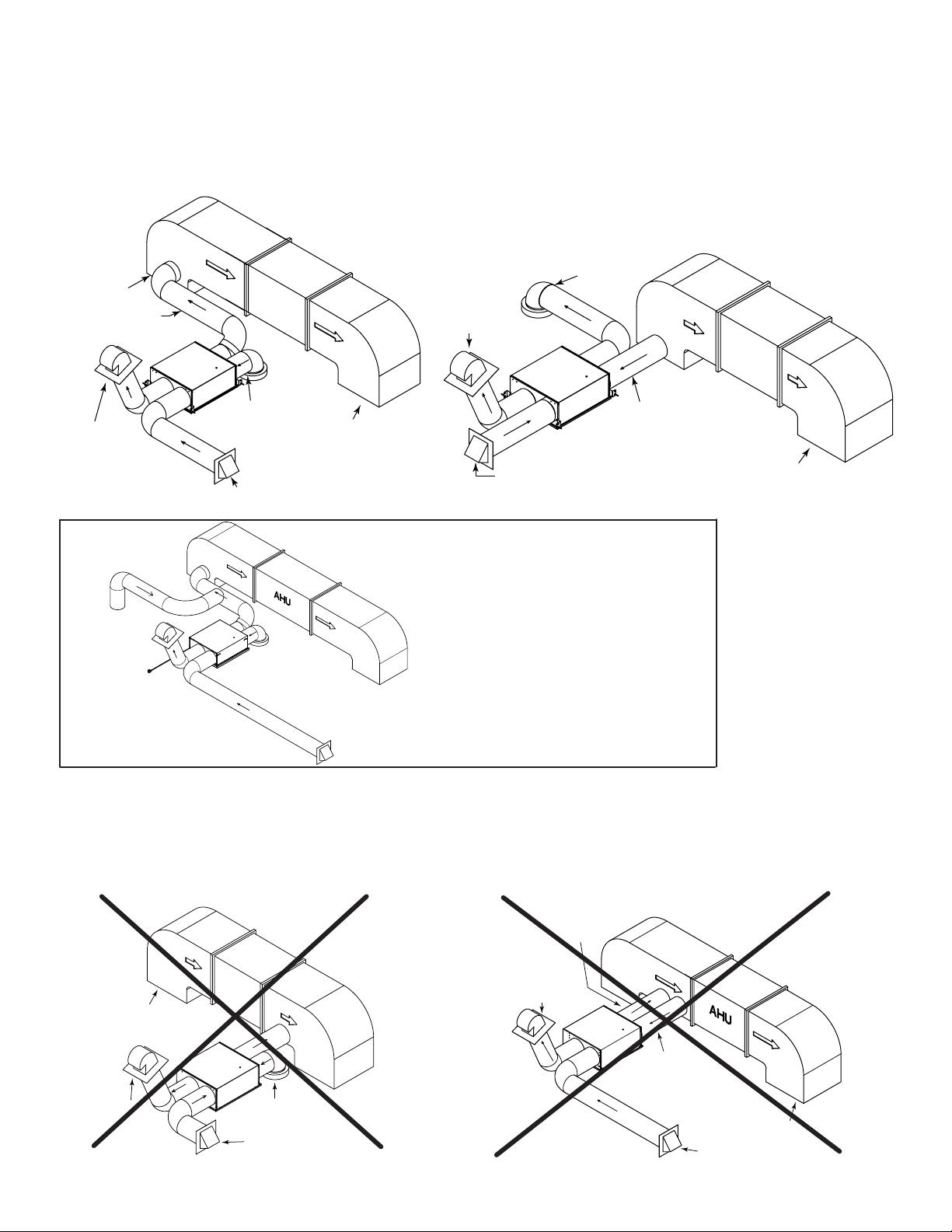
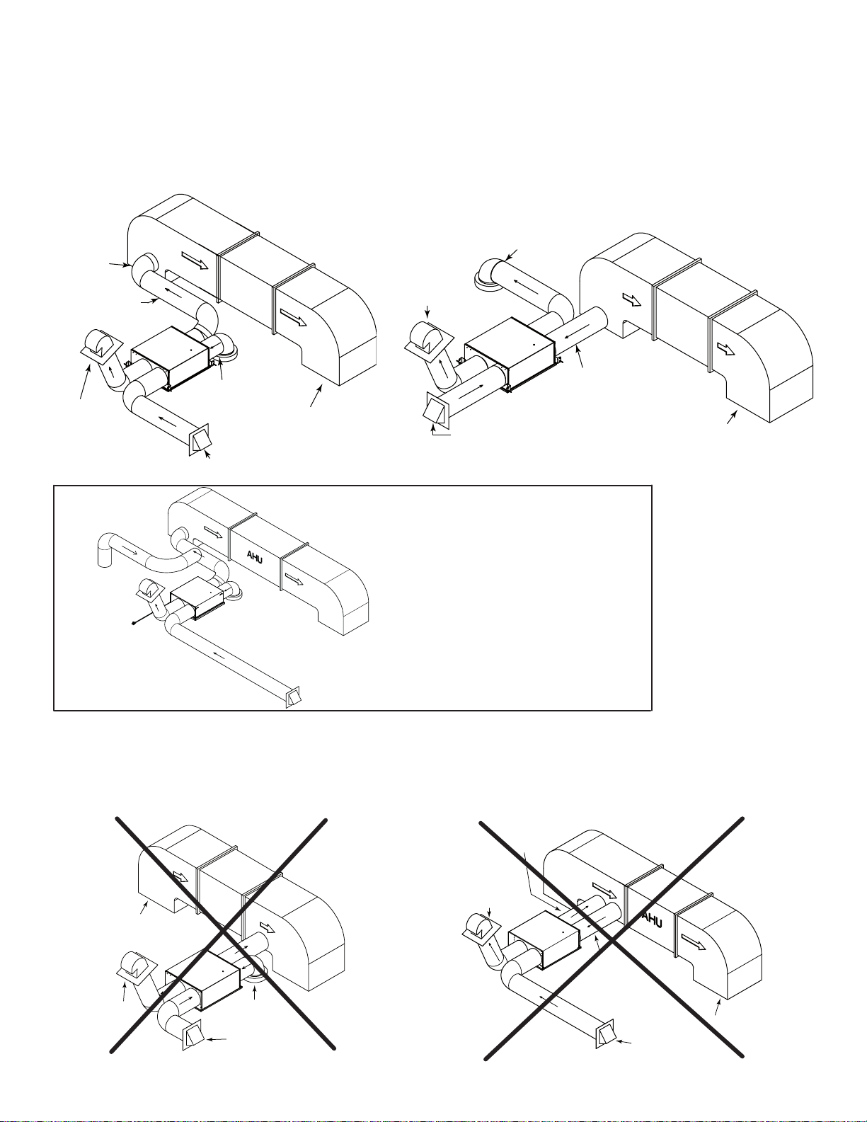
3.2 Combining with an AHU
3.2.1 Recommended configurations
When the distribution of fresh air from the ERV is connected to the return of an AHU (such as in the image below, on the left),
the connection should be done as close as possible from one AHU return grille to ensure proper functionning of the built-in
fresh air damper.
ERV
AHU
Stale air
to outdoors
with backdraft
damper
Return grille
of AHU
Fresh air
from outdoors
Stale air
from home
VH011 4A
Return grille
of AHU
Distribution of
fresh air in AHU
Stale air
from home
ERV
Fresh air
from outdoors
Stale air
to outdoors
with backdraft
damper
AHU supply ducting
and grille to home
AHU
VH0
112A
Stale air from home
connected to return
ducting of AHU
Distribution
of fresh air
using plastic grille
AHU
AHU supply ducting
and grille to home
Stale air
to outdoors
with backdraft
damper
Fresh air
from outdoors
VH0113A
ERV
OPTION 2OPTION 1
3 Installation (cont'd)
ERV
VH011 5A
AHU supply ducting
and grille to home
Stale air from home
connected to return
ducting of AHU
Distribution
of fresh air
connected to return
ducting of AHU
Stale air
to outdoors
with backdraft
damper
Fresh air
from outdoors
3.2.2 Prohibited configurations
Distribution of fresh air from the ERV in the distribution ducting from the AHU (such as in the image below, on the left) may
cause condensation issues during cooling season and must be avoided.
Connecting both distribution of fresh air from the ERV and stale air exhaust in the AHU return ducting (such as in the image
below, on the right) must be avoided.
VJ0162
OPTION 1 - If AHU return duct static
pressure exceeds the -0.15 in w.g.
threshold during AHU operation, indirect
connection combined with a supplemental
return grille or "T" connection with the
conditioned space shall be used to ensure
proper functioning of the built-in fresh air
damper.
8
3 Installation (cont'd)
3.3 Installing the Registers, Ductwork and Hoods
3.3.1 Registers
Refer to applicable building codes to plan where the stale air exhaust registers and fresh air distribution registers should be
installed. Below are some general recommendations.
Stale air exhaust registers:
• Install the stale air exhaust registers where the contaminants are produced: bathroom (up to 2), kitchen, living room, etc.
Position the registers as far from the stairway as possible and in such a way that the air circulates in all the lived-in spaces in
the house.
• If a register is installed in the kitchen, it must be located at least 4 feet away from the cooking applicances.
• Install the registers on an interior wall, 6 to 12 inches below the ceiling OR in the ceiling.
Fresh air distribution registers (Option 2 in 3.2.1):
• Install the fresh air distribution registers in bedrooms, dining rooms, living rooms and basement, if applicable.
• Keep in mind that the fresh air registers must be located as far as possible from the ERV stale air registers.
• Install the registers on an interior wall, 6 to 12 inches below the ceiling OR in the ceiling.
• If a register must be floor installed, direct the airflow up the wall.
WARNING
Never install a stale air exhaust register in a closed room where a combustion device operates, such as a gas
furnace, a gas water heater or a fireplace.
!
3.3.2 Ductwork
• All units ports should be connected to 6” ducts, but can be connected to larger ducts using an appropriate transition.
• If you have to connect rigid ducts to the unit, use a short length (approximately 6”) of flexible duct to avoid transmission of
vibrations. Use a tie wrap and foil tape to connect the flexible duct to the port and to the rigid duct.
• Never use screws to connect rigid ducting to the ports.
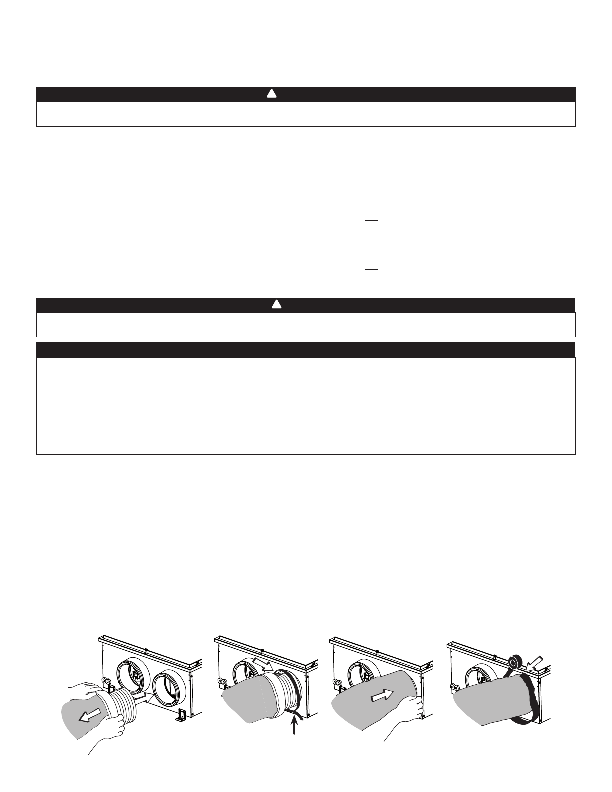
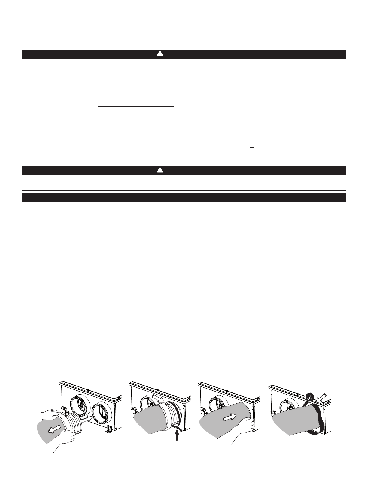
Connecting insulated flexible ducts to the ports:
1. Pull back the insulation to expose the flexible duct.
2. Attach the flexible duct to the port using a tie wrap; ensure tie wrap is tighten to its maximum strength.
3. Pull the insulation over the joint, then pull the vapor barrier (shaded part in illustrations below) over the insulation. Make sure
that the vapor barrier does not tear due to manipulation to avoid condensation within the ducts.
4. Apply foil tape to the joint, making an airtight seal. Avoid compressing the insulation when pulling the tape tightly around
the joint. Compressed insulation loses its R value and causes water dripping in cold climates due to condensation on the
exterior surface of the duct.
NOTE: If sealant mastic has to be used over the foil tape as an extra sealing layer, use water based mastic to ensure material
compatibility with the port.
WARNING
When performing duct connections, always use approved tools and materials. Respect all corresponding laws and
safety regulations. Please refer to your local building code.
!
CAUTION
If ducts have to go through an unconditioned space (e.g.: attic), always use insulated ducts to prevent condensation
formation inside and outside ducts, which could cause material damage and/or mold growth. Moreover, in zone B, if
fresh air to building duct and/or stale air from building duct goes/go through an unconditioned space, these ducts must
be buried with a minimum of R20 insulation in order to prevent heat recovery performance reduction and cooling of
the distributed fresh air to the living areas during winter operation. Also, the unit must be set to operate continuously
in cold conditions (below 50°F) if these ducts have to go through an unconditioned space in zones A and B. Continuous
air movement inside ducts will prevent condensation formation. The unit can be stopped temporarily for maintenance
and/or repair purposes in such conditions.
VJ0134
TIGHTEN TIE WRAP TO ITS
MAXIMUM STRENGTH!
9
• Exhaust hood must have a backdraft damper.
WARNING
!
3 Installation (cont'd)
3.3 Installing the Registers, Ductwork and Hoods (cont'd)
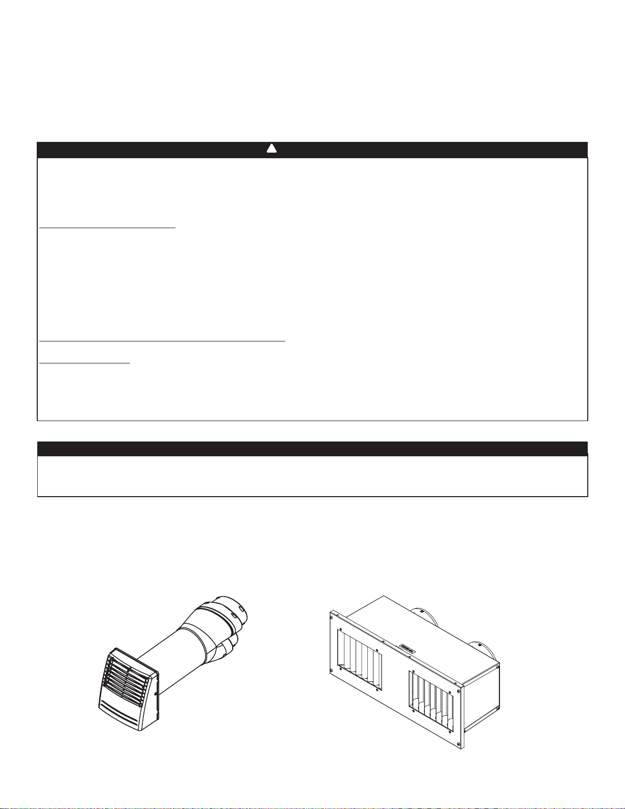
3.4 Installing a Tandem
®
Transition* Kit
If desired, a Tandem transition kit can be used instead of 2 exterior hoods.
• An additional backdraft damper (not included) must be installed on the stale air to outdoors duct following common best
practice. Should the backdraft damper cause an interruption in the insulation of the stale air to outdoors duct, make sure
that insulation is added around the backdraft damper to avoid condensation.
• Follow the instructions included with the tandem termination kit.
*Patented.
VR0003
Tandem VTYIK1
CAUTION
If using a Tandem Transition, a backdraft damper must be installed on the stale air to outdoors duct. If this causes an
interruption in the duct insulation, insulation must be added around the backdraft damper to avoid condensation.
VR0021
Tandem V14695
Make sure intake hood is located at least 10 feet away from any of the following:
• Dryer exhaust, central vacuum vent
• Gas meter exhaust, gas barbecue-grill
• Any exhaust vents or chimney from a combustion source
• Garbage bin and any other source of contamination such as parking lots, streets
For multifamily buildings only:
Make sure exhaust hood is located at least 3 feet away from any of the following:
• Property lines
• Operable openings into buildings (door, window)
• Intake and exhaust hood(s) shall be protected with corrosion-resistant screens, louvers or grilles having openings not less than
1/4 inch and not larger than 1/2 inch.
• Install hood(s) at least at 18 inches away from the ground OR depth of expected snow accumulation, whichever is greater.
To minimize cross-contamination of exhausted stale air into the fresh air intake:
Single detached, attached homes and townhouses:
• Maintain a 6 feet minimum separation distance between outdoor air intake and exhaust hoods OR use an approved factory-built
intake/exhaust combination termination fitting.
Multifamily buildings:
• Maintain a 10 feet minimum separation distance between outdoor air intake and exhaust hoods OR use an approved factory-built
intake/exhaust combination termination fitting.
Ignoring these recommendations could significantly degrade the quality of the incoming air which, in some cases, could result in
health consequences. In the event of a conflict between our recommendations and any local requirements, the latter shall have
priority.
3.3.3 Hoods
Refer to applicable building codes to plan where the stale air exhaust hood and fresh air distribution hood should be
installed. Below are some general recommendations.
10
3 Installation (cont'd)
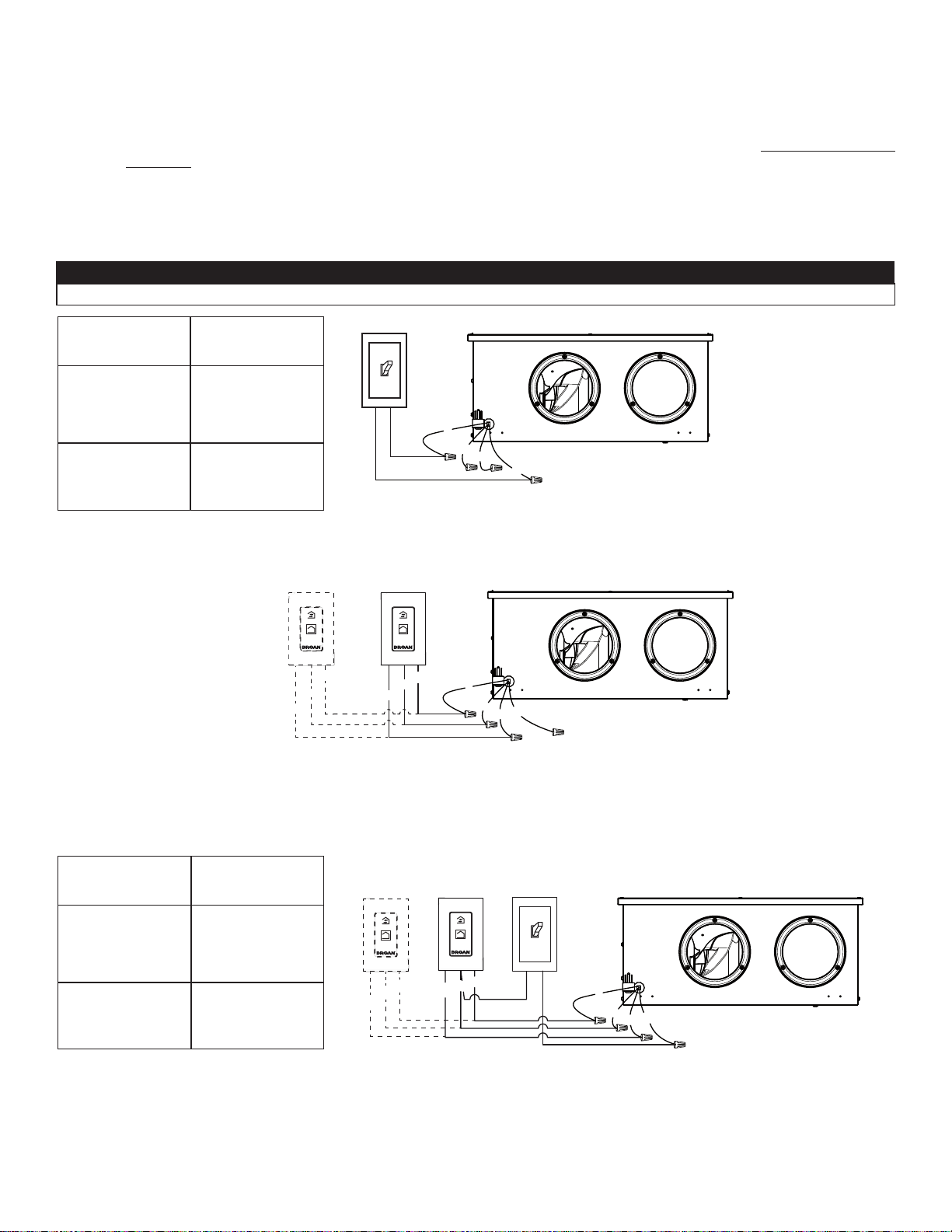
3.5 Connecting the Controls (energized by unit, low voltage)
• Controls are not included with this unit.
• Unit may be connected to a dry contact Standby switch if desired. In such case, unit remains powered on, but is put in
Standby mode when the switch is turned on.
• This ERV can replace up to 2 bath fans. Where this is the case, unit should be connected to a 20-minute override control in
each bathroom.
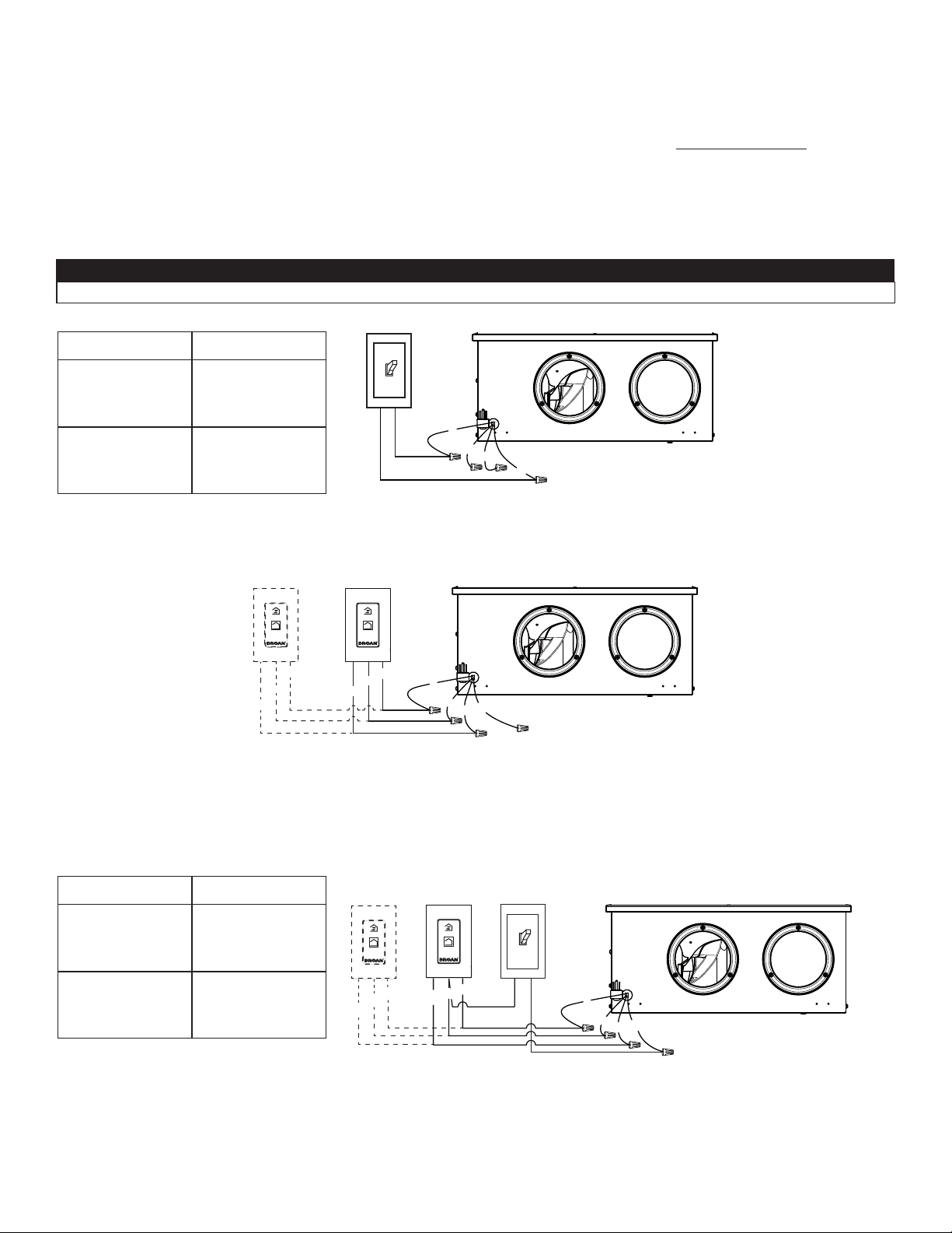
3.5.1 Connecting unit to a Standby switch
Install the dry contact Standby switch in a convenient place and connect it to unit as follows.
3.5.2 Connecting unit to 1 or 2 Broan VB20W 20-minute push-button control(s)
1. Install the 20-minute push-button control in the bathroom(s) following instructions included with the control.
2. Connect it to unit as follows.
R RED
Y YELLOW
B BLACK
G GREEN
R RED
Y YELLOW
B BLACK
G GREEN
G
R
B
Y
VE0357A
G
R
B
Y
OL
OC
I
VE0358A
OL
OC
I
ON ON
CAUTION
Ensure all unused wires are capped off.
Switch position Unit mode
Dry contact ope-
ned
Unit will run in the
selected mode
Refer to 4.1
Dry contact closed
Unit is kept in
Standby mode
3.5.3 Connecting unit to a Standby switch AND 1 or 2 Broan VB20W 20-minute push-button control(s)
1. Install the 20-minute push-button control in the bathroom(s) following instructions included with the control.
2. Install the Standby switch in a convenient place.
3. Connect both with the unit as follows.
R RED
Y YELLOW
B BLACK
G GREEN
G
R
B
Y
OL
OC
I
B
ROAN
VB20W
20-MIN.
PUSH-BUTTON CONTROL
DRY CONTACT
STANDBY SWITCH
VE0359A
ON
ON
I
OC
OL
This connection allows the operation of VB20W push-button controls even if the dry contact standby switch is turned off.
Switch position Unit mode
Dry contact ope-
ned
Unit will run in the
selected mode
Refer to 4.1
Dry contact closed
Unit is kept in
Standby mode
11
3 Installation (cont'd)
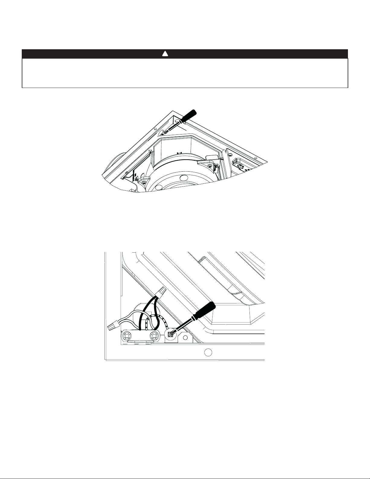
3.6 Connecting the Hardwire Connection (ERVS100S-HW unit only)
1. Open the unit door.
2. Remove and set aside the electrical compartment cover.
3. Install the cable clamp connector included in the kit and tighten so cable clamp screws are accessible. Insert the end of the
flexible conduit inside the unit, through the cable clamp connector.
4. Connect the ground wire from the flexible conduit to the GREEN ground screw inside the electrical compartment. Using
included wire nuts, perform the hardwire connection as follows: BLACK wire to BLACK wire, WHITE wire to WHITE wire.
VE0478
WARNING
Risk of electric shock. Electrical wiring must be done by qualified personnel in accordance with all applicable codes
and standards. Before connecting wires, switch power off at service panel and lock service disconnecting means
to prevent power from being switched on accidentally. Hardwired connection requires the use of flexible conduit.
!
VE0479

12
5. Fasten the flexible metal conduit to the provided cable clamp connector by tightening the screws on each side of the cable
clamp connector. Do not overtighten such that the flexible metal conduit is damaged.
6. Insert all the wires inside the electrical compartment.
7. Reinstall and secure the electrical compartment cover, taking care not to pinch wires. Reinstall the unit door.
8. Restore power at service panel.
3 Installation (cont'd)
3.6 Connecting the Hardwire Connection (ERVS100S-HW unit only) (cont'd)
VE0480
13
4.1.3 Choosing the right settings
Mode:
• Unit is factory set in Standby mode and should be set to the appropriate mode according to local building codes as well as
the floor area of the residence, number of inhabitants and local weather conditions.
RH Limit:
• Unit is factory set to "N" and should normally remain in this setting unless local conditions require otherwise.
4.3 Booting Sequence
When unit is powered on, it will go through a booting sequence during which it will test its components. The booting sequence
will last less than a minute, after which the LED light will blink if there is a problem. If a Broan VB20W 20-minute push-button
control is connected to the unit, it will also blink. The speed of the blinking indicates the nature of the issue:
See the Troubleshooting section of this guide for detailed troubleshooting instructions.
4.2 Prepare the Unit
• Make sure that the protective cardboard is removed from the door, if applicable.
• Verify damper orientation (see section 3.1.2).
Slow blinking: RH and temperature sensor problem
Fast blinking: motor problem
4 Getting the Unit Started
4.1 Unit Settings
• Settings should be changed by the installer after all construction work is over in order to comply to local building codes.
Should the user want to change the settings later on, it should be done by an authorized servicer.
• Unit should never run while the building is still under construction.
• All units are factory set to Standby Mode, with the RH Limit set to the N position.
• See section 3.3.2 for specific details regarding winter operation.
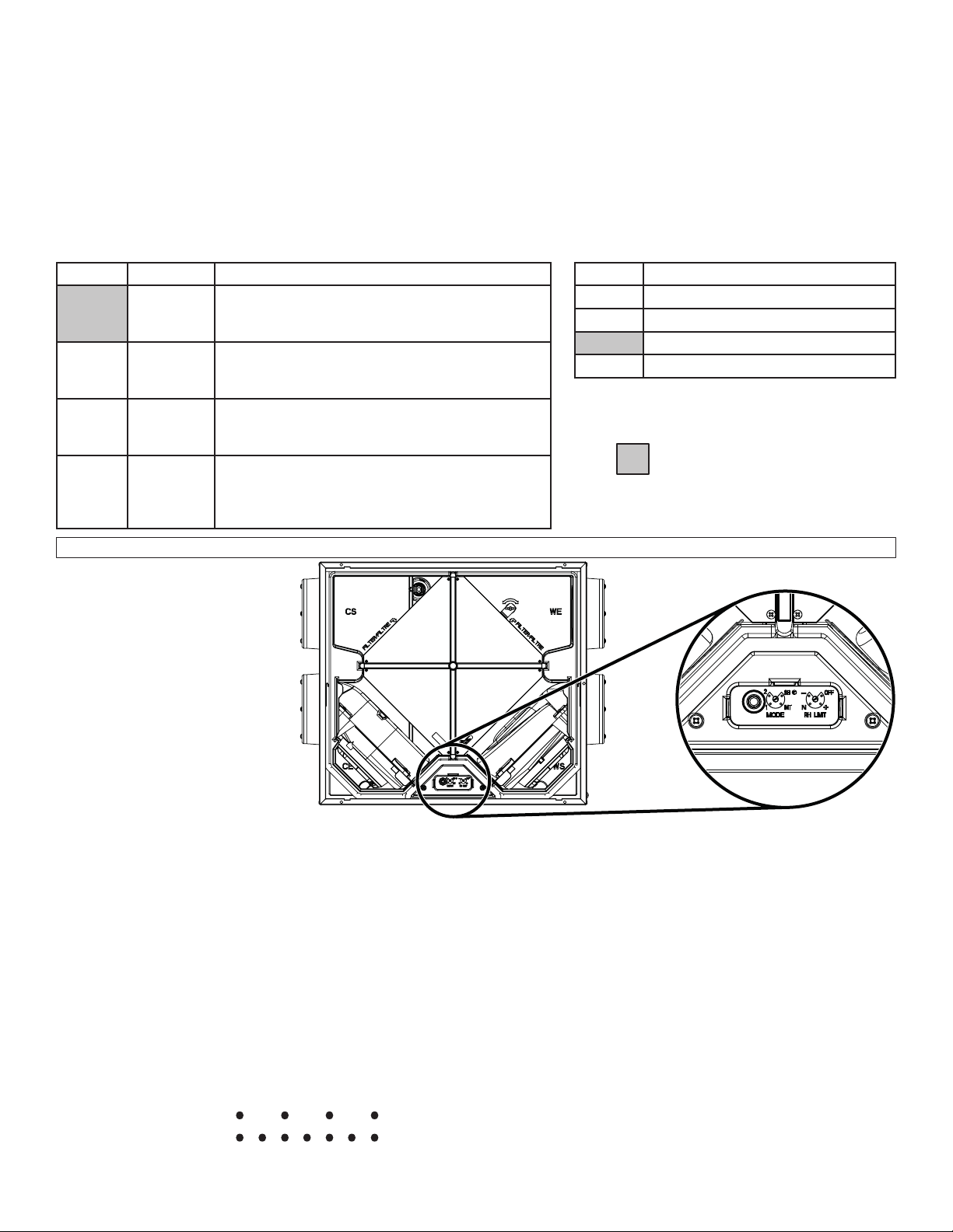
4.1.1 Settings description
4.1.2 Mode and RH Adjustable Controls Location
VD0533
Factory settings
MODE
RH LIMIT
POSITION DESCRIPTION
OFF Relative humidity limit is deactivated.
+ Higher relative humidity limit.
N Factory set relative humidity limit.
- Lower relative humidity limit.
POSITION MODE DESCRIPTION
SB Standby Unit is off.
Unit can be activated in high speed by the
VB20W 20-minute push-button control, if applicable.
INT Intermittent Unit works 20 minutes per hour in low speed.
Unit can be activated in high speed by the
VB20W 20-minute push-button control, if applicable.
1 Low Speed Unit runs at 65 cfm.
Unit can be activated in high speed by the
VB20W 20-minute push-button control, if applicable.
2 High Speed Unit runs at 105 cfm.
Unit can be activated in high speed by the
VB20W 20-minute push-button control, if unit is
deactivated by RH limit.
Remove the
door to access
the MODE and
RH adjustable
controls.
14
5 Maintenance
5.1 Quarterly Maintenance
1. Disconnect unit or turn power off at service panel.
2. Open unit door by following the steps and referring to illustrations below:
Risk of electric shock. Before performing any maintenance or servicing, always turn power off at service panel or
disconnect the unit from the outlet. When cleaning the unit, it is recommended to wear safety glasses and gloves.
WARNING
!
Be careful when opening
the door; water may be
present when there is
a significant difference
between the outside and
inside temperature.
CAUTION
VO0274
3. While holding the core () if unit is installed in or under the ceiling,
loosen the wing nut () and rotate the core retaining bracket (shaded
part in illustration at right). Slide out the core with its filters.
4. Wash both core filters under lukewarm water with mild soap. Rinse
and let dry completely before reinstalling on the core. Refer to the
core label for proper location.
5. Slide the core with its cleaned filters in the unit. Refer to filter location
indicators embossed inside the unit to position adequately the core.
Use the core bracket and wing nut to lock the core in place.
6. Reinstall and close the door, then restore power.
If the unit is installed in or under the ceiling, always hold
the core when rotating the core retaining bracket; failure
to do so will cause the core to fall out.
WARNING
!
ERVS100S-HW
LATCHES
Push on the door retaining
tabs to disengage these
tabs from the unit frame (see
insets).
Rotate the door and
remove it.
ERVS100S-PC
Unlatch both side latches. If the door must be removed to ease maintenance or if the
clearance is not sufficient, remove the nut on the latch then slide the door sideways once
the door slightly opened.

15
5 Maintenance (cont'd)
5.2 Annual Maintenance
Perform steps 1 to 5 of the quarterly maintenance, then continue with the following:
6. Using a vacuum cleaner and a soft brush attachment, remove the dust on the recovery core, the sensor and damper (damper
must open freely).
7. Slide the cleaned core with its cleaned filters in the unit. Refer to filter location indicators embossed inside the unit to posi-
tion adequately the core. Use the core bracket and wing nut to lock the core in place.
8 Reinstall and close the door, then restore power.
9. Clean the exterior hoods.
Do not soak the recovery core in water! The core can easily be damaged especially if it is soaked. The
sensor can be damaged by detergent. Only use a dry cloth to clean the sensor.
CAUTION
6 Warranty
This Broan unit is a high quality product, built and packaged with care. Broan warrants to the original purchaser of its product,
that such products will be free from defects for the period stated below, from date of original purchase.
For all Broan units, the warranty covers parts only against any operational defect. This is a 5-year warranty.
Subject to perform the core maintenance according to user guide recommendations,
the energy recovery core (ERV) has a 5-year warranty.
If any defect should occur, we urge you to read the user guide carefully. If the problem persists, observe the following rules:
RULES TO FOLLOW
If the unit is defective, contact your ventilation contractor (see address on cover page).
The contractor will determine with you the reason for the defect, and if needed, do the replacement or repair.
If ever it is impossible to reach your ventilation contractor, call 1-800-558-1711 (in North America);
the personnel will be pleased to give you the phone number of a distributor or a service center near you.
REPLACEMENT PARTS AND REPAIR
In order to ensure your ventilation unit remains in good working condition, you must use Broan genuine replacement parts only.
Broan genuine replacement parts are specially designed for each unit and are manufactured to comply with all the applicable
certification standards and maintain a high standard of safety. Any third party replacement part used may cause serious damage and
drastically reduce the performance level of your unit, which will result in premature failing. Broan also recommends to contact a Broan
certified service depot for all replacement parts and repair.
BILL OF PURCHASE
No replacement or repair covered by the warranty will be carried out unless the unit is accompanied
by a copy of the original bill of purchase. Please retain your original.
MISCELLANEOUS COSTS
In each case, the labor costs for the removal of a defective part and/or installation of a compliant part will not be covered by Broan.
CONDITIONS AND LIMITATIONS
This unit is created for residential use only and must be used in a building as defined below:
Building: All structures zoned and/or erected for the act, process or art of human or animal habitation and/or the storage or
warehousing of goods.
Residential use: Dwelling, lodging, suite: Building, or part of a building, intended to act as either the domicile to one or several
people which can include general sanitary, food consumption and rest facilities. Buildings of only one room or a
group of rooms including those occupied by a tenant or owner; comprise the lodgings, the individual rooms of the
motels, hotels, rooming/lodging houses, boarding/half-way/foster homes, dormitories, and suites, as well as the
stores and the business establishments constituted by only one room in a dwelling.
Commercial use: Agricultural establishment, commercial establishment for assembly, care, or detention: Building or part of a building
that does not contain a dwelling, situated on land dedicated to agriculture or farming and used primarily to shelter
animals, or for the production, the storage or the treatment of agricultural or horticultural products or animal food.
Building or part of a building, used for the display or retail of goods, professional or personal services, or commodities.
Building, or part of a building used by persons gathering for civic activities, religious or political assembly, tourism,
educational/vocational training, recreation or the consumption of food or drink. Building, or part of a building used
to shelter persons of impaired physical or psychological states, persons requiring palliative care or medical
treatments, or persons for reasons out of their control, cannot escape harm or threat of danger autonomously.
Industrial use: Building, or part of a building, used for the assembly, the manufacture, the creation, the treatment, the repair or the
storage of products and combustible materials and that contain fuels that when ignited or exploded in sufficient
quantity may constitute a risk of fire.
The above warranty applies to all cases where the damage is not a result of poor installation, improper use, mistreatment or negligence, acts of
God, or any other circumstances beyond the control of Broan. Furthermore, Broan will not be held responsible for any bodily injury or damage
to personal property or real estate, whether caused directly or indirectly by the Broan unit. This warranty supersedes all prior warranties.
16
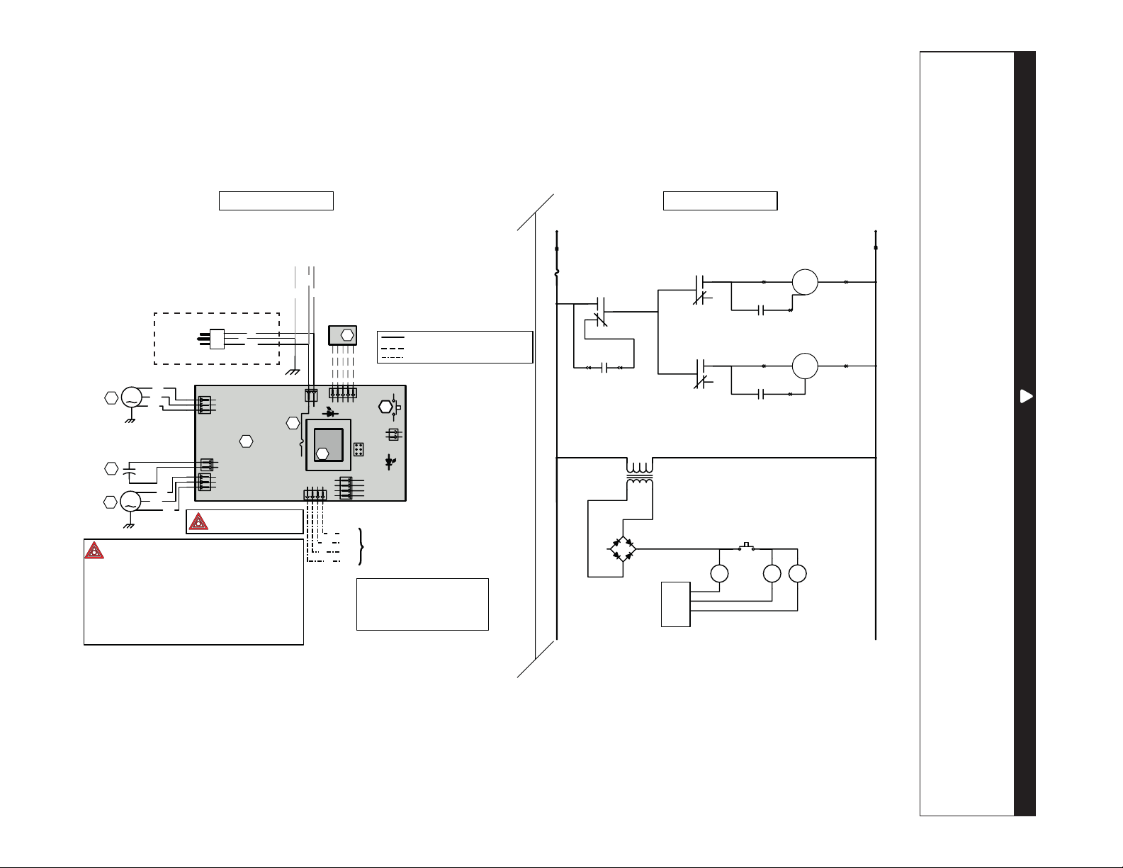
7 Wiring Diagram
WARNING
• Risk of electric shocks. Before performing any maintenance or servicing, always turn power off at service panel
or disconnect the unit from its power source.
• This product is equipped with an overload protection (fuse). A blown fuse indicates an overload or a short-circuit
situation. If the fuse blows, unplug the product from the outlet or, if hard-wired, turn off power at service panel.
Discontinue using the unit and contact technical support.
!
LINE
N
EUTRAL
120 VAC
J1-1
J1-2
M
F1
LOGIC DIAGRAM
M
C2 MOTOR SPEED
SUPPLY FAN
MOTOR M2
K2
K1
K3
J4-1
J4-2
J4-3
EXHAUST MOTOR
CAPACITOR
SUPPLY MOTOR
CAPACITOR
J3-1
J3-2
J3-3
J2-1 J2-2
T1
9.5 VAC
S1 EMBEDDED
DOOR SWITCH
K2 K1 K3
CPU
WIRING DIAGRAM
LINE VOLTA GE FACTORY WIRING
CLASS 2 LOW VOLTA GE FACTORY WIRING
CLASS 2 LOW VOLTA GE FIELD WIRING
RH SENSOR
A2
S1
DOOR INTERLOCK
SWITCH
1
2
1
2
1
2
3
1
2
3
J4
J2
J3
A1
ELECTRONIC
ASSEMBLY
F1
3A
3AG T
YPE
1
2
J1
J6
1 2345
120 VAC
60 Hz
W
G
BK
T1
J7
ICP
J9
4
3
2
1
J8
J5
1 234
OVERRIDE SWITCH
(OPTIONAL)
G
BK
Y
R
OC
OL
I
STB
M1
M2
C2
BK
BL
BR
BK
BL
BR
COLOR CODE
BLACK
BLUE
BROWN
GREEN
BK
BL
BR
G
RED
WHITE
YELLOW
R
W
Y
Critical characteristic.
NOTES
1.
Protected against fire with
UL listed/CSA Certified line fuse.
2. If any of the original wire, as supplied, must
be replaced, use the same equivalent wire.
3. Field wiring must comply with applicable
codes, ordinances and regulations.
4. Remote controls (class 2 circuit) available,
see instruction manual.
5. Furnace fan circuit must be class 2 circuit only.
VE0477A
EXHAUST FAN
MOTOR M1
ref: 24605_REV-A
W
BK
G
120 VAC
60 Hz
Ground
Line
Neutral
ERVS100S-PC
ERVS100S-HW
-
+
~
~
17
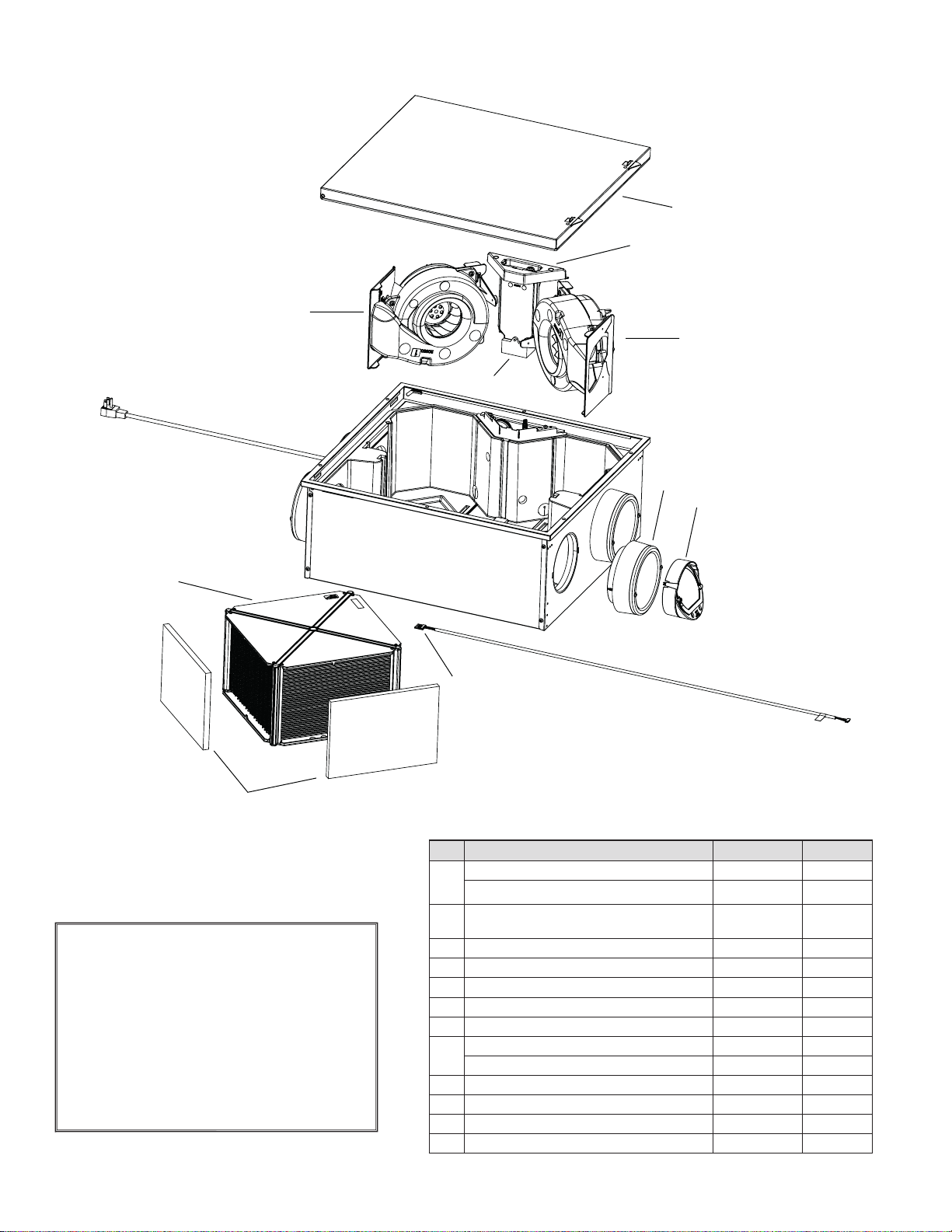
8 Service Parts
REPLACEMENT PARTS AND REPAIR
In order to ensure your ventilation unit remains in good
working condition, you must use Broan-NuTone LLC
genuine replacement parts only. The Broan-NuTone
LLC genuine replacement parts are specially designed
for each unit and are manufactured to comply with all
the applicable certification standards and maintain a
high standard of safety. Any third party replacement
part used may cause serious damage and drastically
reduce the performance level of your unit, which will
result in premature failing. Also, Broan-NuTone LLC
recommends to contact a Broan-NuTone LLC certified
service depot for all replacement parts and repairs.
B
C
D
F
G
I
J
K
E
H
VL0083
NO. DESCRIPTION PART NO. QTY.
1
DOOR ERVS100S-HW SV66548 1
DOOR ERVS100S-PC
sv66549
1
2
PCB AND SWITCH SPRING
(PLASTIC HOLDER NOT INCLUDED)
SV62721 1
3 BLOWER KIT CE SV62724 1
4 BLOWER KIT WS SV62723 1
5 6” ISOLATED METAL PORT KIT SV62718 4
6 DAMPER SYSTEM KIT SV62717 1
7 RH-TEMP SENSOR SV62719 1
8
FILTER KIT (2) SV21029 1
OPTIONAL MERV 8 FILTERS (2) V21030 1
9 ERV CORE SV61223 1
10 LOW SPEED CAPACITOR 18 µF SV62722 1
* CORE LOCKING DEVICE KIT SV61237 1
* HARDWARE KIT SV22079 1
* NOT SHOWN.
ERVS100S-HW DOOR SHOWN

18
9 Troubleshooting
If the unit does not work properly, reset the unit by removing power at service panel or unplugging it for one minute and then
restore power at service panel or replug the unit. If it still not working properly, refer to table below.
PROBLEMS POSSIBLE CAUSES YOU SHOULD TRY THIS
1 Unit does not start.
• No power to power outlet or to
wires on power cable.
• Unit door not properly closed.
• PCB plastic holder tabs unclipped.
• Check the breaker in the distribution panel.
• ERVS100S-PC only: Test the power outlet with another
electrical device (e.g.: a lamp). If it does not work, call an
electrician.
• ERVS100S-HW only: Use a voltmeter to check power cable
wires. If there is no voltage detected, call an electrician.
• Ensure the unit door is properly closed.
• Ensure the PCB plastic holder tabs are engaged in their
slots and the PCB is well seated on its holder.
2
LED blinks rapidly on
push button and unit
(motor error).
• Motor harness damaged or
misconnected.
• Defective PCB, motor assembly or
low speed capacitor.
• Check both motor harness connections, ensure that
connectors are connected to their appropriate places, the
wires are not damaged and connector pins are not corroded.
• Open the door and push on door switch spring to reset the
error and activate the unit self test during booting sequence.
Both motors must start in high speed for 10 seconds, then go
on low speed for 10 seconds. If both motors do not go on
high speed; replace the PCB.
• If one motor does not start on high speed, inverse both motors
connection and start again the self test; if the motor still not
start on high speed, replace the motor asembly and if the
problem is now on the other motor, replace the PCB.
• If both motors run in high but not in low speed, replace the low
speed capacitor. If only one motor runs in low speed, replace
the defective motor assembly.
3
LED blinks slowly on push
button and unit (RH and
temperature sensor error).
• RH and temperature sensor
misconnected.
• Defective RH and
temperature sensor.
• Check the sensor harness connection, ensure that connector
is connected to its appropriate place, the wires are not
damaged and connector pins are not corroded.
• Open the door and push on door switch spring to reset the
error and activate the unit self test during booting sequence.
Both motors must start in high speed for 10 seconds, then go
on low speed for 10 seconds. After that, the unit will test its
temperature and RH sensor. If the LED is still blinking slowly,
replace the defective RH and temperature sensor
4
The wall control does not
work.
• Unit not compatible with control.
• The wires may be in reverse position.
• The wires may be misconnected.
• The wires may be broken.
• Defective wall control.
• Check table on page 2 for control compatibility.
• Ensure that the color coded wires have been connected to
their appropriate places.
• Ensure the wires are correctly connected.
• Inspect every wire and replace any damaged ones. If wires
are hidden into walls, test the control using a shorter wire.
• Replace the wall control.
5
Unit lets too much
moisture entering
the building during
ventilation.
• Unit backdraft damper misfunction.
• Wrong setting of RH limit.
• Check if the unit backdraft damper is closed when the unit
is off, if not, verify the orientation of the damper assemply
(“TOP” engraving on damper support must be on top),
verify if magnet is in place in the damper support, verify if
metal clip is in place on damper. Damper must open freely.
• Verify RH limit adjusment (factory setting is “N” for South
and humid climate), adjust the RH limit to “-” position to
reduce humidity limit of ventilation. Ventilation speed can be
reduced by changing mode allowing less moisture to enter
the building.
6
Unit stops ventilating too
often.
• Wrong setting of RH limit. • Verify RH limit adjusment (factory setting is “N” for South and
humid climate), adjust the RH limit to “+” position to increase
humidity limit of ventilation (allowing more ventilation time),
or set the RH limit to “OFF” position to deactivate the sensor.
WARNING
Risk of electric shocks. Electronic board connections must be checked by qualified personnel only.
!
MANUAL DE INSTALACIÓN Y DEL USUARIO PARA
BROAN ERVS100-HW Y ERVS100S-PC
SÓLO PARA USO RESIDENCIAL
0009
!
0009
!
LEA Y CONSERVE ESTAS INSTRUCCIONES
INSTALADOR: ENTREGUE ESTE MANUAL AL CLIENTE
Broan-NuTone LLC, 926 west State Street, Hartford, Wisconsin, USA 800-558-1711 broan-nutone.com
REGISTRE SU PRODUCTO EN LÍNEA EN: www.broan-nutone.com/register
Para obtener más información, visitar nuestro sitio www.broan-nutone.com
22077 rev. M
VB0342
VB0347
ERVS100S-HW ERVS100S-PC
2
CONTROLES AUXILIARES ALIMENTADOS POR LA UNIDAD
TEMPORIZADOR DE ENCENDIDO DURANTE 20 MINUTOS VB20W DE BROAN
INTERRUPTOR ESTÁNDAR DE ESPERA DE CONTACTO SECO
Con el fin de hacer hincapié en determinada información, en este manual se emplean los siguientes símbolos:
Se refiere a una instrucción que, de no seguirse, podría causar daños corporales e incluso la muerte.
Se refiere a una instrucción que, de no seguirse, podría dañar gravemente el aparato o sus componentes.
NOTA: indica una información complementaria que es necesaria para completar totalmente una instrucción.
ADVERTENCIA
!
PRECAUCIÓN
OBSERVACIONES SOBRE ESTE MANUAL
OBSERVACIONES SOBRE ESTOS APARATOS
LÍMITES
Sólo para instalaciones residenciales. El trabajo de instalación y el cableado eléctrico han de ser efectuados por personal cualificado conforme a todos
los códigos y normas aplicables, incluso los relativos a lugares con alto riesgo de incendio.
ADVERTENCIA
0009
!
PARA REDUCIR EL RIESGO DE INCENDIO, CHOQUE ELÉCTRICO O HERIDAS CORPORALES, SIGA LAS INDICACIONES
SIGUIENTES:
1. Utilice el aparato únicamente de la manera prevista por el fabricante. Si tiene preguntas, póngase en contacto con el fabricante en la dirección o en
el teléfono que aparecen en la garantía.
2. Antes de realizar tareas de mantenimiento o de limpiar el aparato desenchufe el cable de alimentación de la toma eléctrica o apáguelo en el tablero
de servicio.
3. Este aparato no ha sido pensado para la combustión ni para el aire de dilución de aparatos que queman combustible.
4. Al cortar o taladrar en la pared o en el techo, procure no dañar el cableado eléctrico ni otras instalaciones ocultas.
5. No use el aparato con un dispositivo de control de velocidad de semiconductores diferente de los que aparecen en el cuadro siguiente:
6. El aparato debe conectarse a tierra. Sólo para el aparato ERVS100S-PC: El cable de alimentación lleva un enchufe con toma de tierra de 3 patillas
para su seguridad personal. Debe enchufarse en una toma de corriente para tres patillas, conectada a tierra de acuerdo con el código eléctrico
nacional y los códigos y ordenanzas locales. No retire la patilla de la toma de tierra. No utilice el aparato con un cable prolongador.
7. No instale el aparato en un espacio donde se cocina ni lo conecte directamente a otro aparato.
8. No lo use para evacuar materias ni vapores peligrosos o explosivos.
9. Esta unidad debe ser protegida contra la intemperie.
10. Para la instalación, el mantenimiento o la limpieza del aparato se aconseja llevar lentes y guantes de seguridad.
11. Cuando la reglamentación local aplicable sea más restrictiva en materia de instalación o certificación, dicha reglamentación prevalecerá sobre las
exigencias de este manual y el instalador acepta atenerse a dicha reglamentación y asumir los gastos correspondientes.
PRECAUCIÓN
1. No use el aparato durante la construcción o renovación de su casa o cuando se lije paredes de yeso. Ciertos tipos de polvo y vapores pueden dañar
su sistema.
2. Para mayor información sobre otras exigencias, lea la etiqueta de especificaciones que viene en el aparato.
3. Asegúrese de sacar el aire al exterior. No introduzca ni evacue el aire en espacios situados entre paredes, en el techo o en un desván, en sótanos
pequeños ni en cocheras. No intente recuperar el aire de salida de una secadora o de una campana.
4. Aparato para instalación residencial únicamente, de acuerdo con las exigencias de la norma 90B de la NFPA (para un aparato instalado en EE.UU.).
5. No pase ningún conducto de aire por encima o a menos de 2 pies de una caldera o de su cámara de alimentación, de un calentador o de otro aparato
que genere calor.
6.
La instalación de los conductos debe hacerse de conformidad con todos los códigos locales y nacionales aplicables.
7. Al ausentarse de la vivienda durante un periodo largo (más de dos semanas), una persona responsable debería verificar regularmente si el aparato
funciona correctamente.
8. Si los conductos pasan a través de un espacio no acondicionado (como un desván), el aparato debe funcionar constantemente, excepto cuando haya
que hacer tareas de mantenimiento o reparaciones. Asimismo, la temperatura ambiente de la casa nunca debería bajar de 65°F.
9. Las piezas mecánicas y electrónicas del aparato deberían ser examinadas por personal de servicio cualificado al menos una vez al año.
10. Asegúrese en todo momento de que la admisión exterior de aire y las bocas de aire viciado estén libres de nieve durante el invierno. Es importante
comprobar que, durante una gran tormenta de nieve, el aparato no introduzca nieve. Si fuera el caso, por favor, apague el aparato durante unas
horas.
11. Dado que el sistema de control electrónico del aparato utiliza un microprocesador, es posible que no funcione correctamente debido a los ruidos
externos o a fallas de alimentación muy cortas. Si esto ocurre, desenchufe el aparato y espere aproximadamente 10 segundos. A continuación,
enchufe de nuevo el aparato (o restablecer el encendido en el panel de servicio).
12. No debería hacer uso excesivo de aparatos de fragrancia o de químicos porque pueden dañar el material de los componentes del aparato.
13. Para una instalación en una cochera, asegúrese de que la puerta del aparato siempre sea cerrada, excepto durante mantenimiento asistido, para
reducir las probabilidades que humos de escape estén introducidos en la vivienda.
3
1 Zona de instalación segura
HELENA
OLYMPIA
SALEM
BOISE
BISMARCK
SALT LAKE CITY
ST. PA UL
DES MOINES
MADISON
HARRISBURG
SACRAMENTO
DENVER
TOPEKA
DETROIT
INDIANAPOLIS
SANTA FE
SPRINGFIELD
OKLAHOMA CITY
PHOENIX
COLUMBUS
NASHVILLE
ATLANTA
BATON ROUGE
AUSTIN
COLUMBIA
RALEIGH
WASHINGTON
HARTFORD
BOSTON
RENO
VN0010
A
B
Los requisitos de instalación varían en las zonas A y B que se muestran en el mapa de abajo, ver las secciones 3.1 a 3.3.2 para
obtener detalles específicos y avisos por cada tipo de instalación.
ÍNDICE
1 Zona de instalación segura........................................................................................ 3
2 Preparación de la unidad .......................................................................................... 4
2.1 Elección de una ubicación adecuada para el aparato ............................................................................ 4
2.2 Tipo de conexión eléctrica (conectado con cable de alimentación o conectado con cableado local) 4
3 Instalación ............................................................................................................4-12
3.1 Colocación de la unidad ...................................................................................................................... 4-6
3.2 Combinación con una AHU .................................................................................................................... 7
3.3 Instalación de los registros, conductos y bocas exteriores .................................................................. 8-9
3.4 Instalación de un conjunto de cambio de sección Tandem®* ............................................................... 9
3.5 Conexión de los controles .................................................................................................................... 10
3.6 Conectar el cableado local (aparato ERVS100S-HW solamente) .................................................... 11-12
4 Puesta en marcha de la unidad ............................................................................... 13
4.1 Parámetros de la unidad ....................................................................................................................... 13
4.2 Preparación de la unidad ...................................................................................................................... 13
4.3 Secuencia de inicio ............................................................................................................................... 13
5 Mantenimiento ...................................................................................................14-15
5.1 Mantenimiento trimestral ..................................................................................................................... 14
5.2 Mantenimiento anual ............................................................................................................................ 15
6 Garantía ...................................................................................................................15
7 Diagrama de cableados .........................................................................................16
8 Piezas de repuesto .................................................................................................. 17
9 Solución de problemas............................................................................................18
4
2 Preparación de la unidad
• Examine el exterior de la unidad para ver si hay daños debidos al envío.
• La unidad no debería funcionar nunca cuando el edificio esté en construcción.
• ERVS100S-HW se envía con material de protección para la puerta. Déjelo durante la construcción y retirelo una vez el techo
terminado.
3 Instalación
3.1 Colocación de la unidad
• La unidad puede instalarse entre vigas separadas por 24”, sobre vigas separadas por 24” en posición inversa o bajo el techo,
mediante soportes. Entre las piezas provistas hay un juego de 4 soportes así como los tornillos necesarios.
• Si está conectado por enchufe (sólo para el aparato ERVS100S-PC, debe haber una toma eléctrica estándar de 3 patillas
a menos de 28” de la unidad y debe conectarse a un circuito eléctrico de 15 amp. Se recomienda marcar el circuito para
identificar este sistema como el Sistema de Aire Fresco.
• Prevea un espacio libre de 12” para poder retirar la puerta, el núcleo y los filtros con fines de mantenimiento.
3.1.1 Instalación en el techo (entre vigas separadas por 24”)
ERVS100S-HW solamente
1. Trace una línea a nivel en ambas vigas, a 1/2” o 1” de la base, para ubicar
los soportes de la unidad (con 1/2”, el perímetro de la puerta de la unidad
descansará en el material del techo, mientras que con 1” se obtendrá
una instalación a nivel; véanse las imágenes A y B en la página siguiente).
En una de las vigas atornille a mitad, sobre la línea de nivel, dos tornillos
n.° 8 x 1½” provistos, dejando un espacio de 23” entre ellos.
2. Coloque los 4 soportes en la unidad, como puede
verse en la ilustración de la derecha; utilice para ello
dos tornillos n.° 10 x 5/8" por soporte (provistos).
CONSEJO: Atornille a mitad los tornillos para
permitir ajustes entre las vigas; observe los detalles
de la imagen de la derecha: la de la izquierda
muestra la distancia mínima y la de la derecha la
distancia máxima.
3. Cuelgue el lado más ligero de la unidad en los tornillos
instalados en la viga utilizando los orificios más grandes
de los soportes.
4. Levante el otro lado de la unidad y sujételo a la otra viga
con un tornillo n.° 8 x 1½” por soporte, introduciéndolo
en el orificio más pequeño de los soportes.
VD0391A
VD0394
VD0390
2.1 Elección de una ubicación adecuada para el aparato:
• En una zona de la vivienda donde la temperatura ambiente se mantenga entre 50°F y 135°F;
• Lejos de las zonas de estar (comedor, sala de estar, dormitorio), de ser posible para reducir el nivel de ruido;
• De forma que sea fácil acceder al interior del armario para las tareas de mantenimiento;
• Cerca de una pared exterior para limitar la longitud del conducto flexible aislado que sale del aparato o llega a él;
• Lejos de chimeneas calientes, tableros eléctricos y otros lugares que presenten peligro de fuego;
• Dentro de 28 pulg. de una fuente de alimentación (toma de corriente estándar, unidad ERVS100S-PC solamente).
2.2 Tipo de conexión eléctrica (conectado por enchufe o conectado con cableado local)
• Conforme a sus necesidades y a los códigos aplicables, asegúrese de usar el modelo apropiado (ERVS100S-PC: aparato
conectado por enchufe y ERVS100S-HW: aparato conectado con cableado local).
Se debe instalar el aparato en orientación horizontal como se muestra en la sección 3.1.
5
3.1.1 Instalación en el techo (entre vigas separadas por 24”) (cont.)
5. Sujete los primeros soportes instalados en la viga con un tornillo n.° 8 x 1½”
por soporte, introduciéndolo por el orificio más pequeño y apriete
completamente los tornillos de los soportes en la unidad.
6. Extienda el aislante sobre la unidad y alrededor.
3 Instalación (cont.)
3.1 Colocación de la unidad (cont.)
VD0393
VD0386
1/2”
1”
1
2
MATERIAL DEL TECHO
DE 1/2"
MATERIAL DEL TECHO
DE 1/2"
AISLANTE
(SOBRE Y ALREDEDOR DE
LA UNIDAD)
AISLANTE
(SOBRE Y ALREDEDOR DE
LA UNIDAD)
PRECAUCIÓN
Si la unidad se instala en el techo en el desván en la zona A, debe
extenderse aislante sobre ella. La temperatura ambiente donde
se instala la unidad debe mantenerse entre 50°F y 135°F.
ZONA A
PRECAUCIÓN
Cuando se instala en el techo en un espacio acondicionado (p.ej.
un desván), sobre la unidad en zona B, una carcasa sellada debe
instalarse sobre y alrededor de la unidad para evitar fugas de
aire, condensación y riesgos de crecimiento de hongos. Aislante
debe extenderse sobre y alrededor de la carcasa. Los conductos
deben pasar a través de la carcasa sellada y deben sellarse a la
carcasa.
ZONA B
7. Extienda el aislante sobre la carcasa sellada y alrededor.
VD0521
AISLANTE
(SOBRE Y ALREDEDOR DE LA CAR-
CASA SELLADA)
EL MARCO DE LA PUERTA PUEDE MONTARSE ENRASADO CON EL
MATERIAL DEL TECHO COMO SE MUESTRA EN LA OPCIÓN 2 ARRIBA.
Se necesita un espacio libre de aprox.
1" sobre la unidad para garantizar que
la unidad no entre en contacto con la
carcasa.
6
9¼”
VD0385
CLÓSET PROFUNDO DE 24"
3 Instalación (cont.)
3.1 Colocación de la unidad (cont.)
3.1.2 Zona A solamente - Instalación en el desván sobre el aislante (unidad con la puerta en la parte superior)
ERVS100S-HW y ERVS100S-PC
1. Gire la clapeta de retención 180° (no se necesita herramienta) de forma que se ponga en posición cerrada y la palabra
"TOP" gravada en la clapeta esté arriba una vez que la unidad esté colocada.
2. Coloque los soportes en la unidad, como puede verse en la ilustración de abajo; utilice para ello dos tornillos n.° 10 x 5/8"
por soporte (provistos).
3. Sujete la unidad a los soportes por medio de un tornillo no 8 x 1½" por soporte (provisto).
4. IMPORTANTE: En un desván no ventilado sin laminado de barrera radiante, material aislante debe añadirse sobre la unidad y
alrededor para evitar exceso de calor en la unidad, Asegurese que el acceso esté mantenido para el mantenimiento del producto.
3.1.3 Instalación debajo del techo (en un espacio acondicionado)
1. Coloque los soportes en la unidad, como puede verse en la ilustración de
arriba; utilice para ello dos tornillos n.° 10 x 5/8" por soporte (provistos).
2. Sujete la unidad al techo con dos tornillos n.° 8 x 1½” por soporte
(provistos), procurando no sujetarla sólo al panel mural.
VH0111
PUERTA
N.° 10 X 5/8"
N.° 8 X 1½"
CONSERVAR UN ESPACIO INFERIOR DE 12"
PARA FINES DE MANTENIMIENTO
PRECAUCIÓN
La temperatura ambiente donde se instala la unidad debe mantenerse entre 50°F y 135°F. Debe añadirse
aislante sobre la unidad si la temperatura en el desván supera este límite en verano para proteger
componentes electrónicos de una exposición a altas temperaturas.
Extienda el aislante alrededor de la unidad, después utilice una placa aislada para
conductos de aire para cubrir la puerta de la unidad, para conservar el acceso al
interior de la unidad. No olvide prever un espacio libre de 12” para poder retirar la
puerta, el núcleo y los filtros con fines de mantenimiento.
VH0116
PLACA PARA
CONDUCTOS
ERVS100S-HW MOSTRADO
NOTA: Verificar los códigos aplicables.
7
3.2 Combinación con una AHU
3.2.1 Configuraciones aconsejadas
Cuando la distribución del aire fresco desde el ventilador de recuperación de energía (ERV, en sus siglas en inglés) esté
conectada al retorno de una unidad del armario de tratamiento de aire (AHU, en sus siglas en inglés) (como en la imagen de
abajo a la izquierda), la conexión debería hacerse lo más cerca posible de una rejilla de retorno de AHU para que la clapeta
de aire fresco integrada funcione debidamente.
ERV
AHU
Aire viciado
hacia el exterior
con clapeta
de retención
Rejilla de retorno
de AHU
Aire fresco
del exterior
Aire viciado
de la vivienda
VH011 4E
Rejilla
de retorno
de AHU
Distribución de
aire fresco en AHU
Aire viciado de
la vivienda
ERV
Aire fresco
del exterior
Aire viciado
hacia el exterior
con clapeta
de retención
Conducto de alimentación
y rejilla de la AHU hacia
la vivienda
AHU
VH0112E
Aire viciado de la vivienda
conectado al conducto de
retorno de la AHU
Distribución de aire fresco
mediante rejilla de plástico
AHU
Conducto de alimentación y rejilla
de la AHU hacia la vivienda
VH0113E
Aire viciado
hacia el exterior
con clapeta
de retención
Aire fresco
del exterior
ERV
OPCIÓN 2OPCIÓN 1
3 Instalación (cont.)
Aire viciado de la vivienda
conectado al conducto de
retorno de la AHU
Conducto de alimentación y rejilla
de la AHU hacia la vivienda
Aire viciado
hacia el exterior
con clapeta
de retención
Aire fresco
del exterior
Distribución de aire fresco
conectado al conducto de
retorno de la AHU
ERV
VH011 5E
3.2.2 Configuraciónes prohibidas
La distribución de aire fresco del ERV en el conducto de distribución del AHU (como en la imagen de abajo a la izquierda)
puede causar problemas de condensación durante la estación fría y debe evitarse.
La distribución de aire fresco y la salida del aire viciado del ERV conectado en el conducto de retorno del AHU (como en la
imagen de abajo a la derecha) es prohibida.
VJ0162
OPCIÓN 1 - Si la presión estática del
conducto de retorno del AHU supera el
umbral -0,15 pulgada de agua durante el
funcionamiento del AHU, una conexión
indirecta combinada con una rejilla de
retorno adicional o una conexión en "T" con
el espacio acondicionado se debe utilizar
para garantizar el funcionamiento adecuado
de la compuerta de aire fresco integrada.
8
3 Instalación (cont.)
3.3 Instalación de los registros, conductos y bocas exteriores
3.3.1 Registros
Consulte los códigos de construcción aplicables para planificar dónde debería instalar los registros de salida de aire viciado y
los registros de distribución de aire fresco. A continuación se presentan algunos consejos generales.
Registros de salida de aire viciado:
• Instale los registros de salida de aire viciado donde se produzcan contaminantes: cuarto de baño (hasta 2), cocina, sala de estar, etc.
Coloque los registros lo más lejos posible de la escalera y de forma que el aire circule en todos los espacios de estar de la vivienda.
• Si se instala un registro en la cocina, debe colocarse al menos a 4 pies de distancia de los electrodomésticos para cocinar.
• Instale los registros en una pared interior, de 6 a 12 pulgadas por debajo del techo O en el techo.
Registros de distribución de aire fresco (Opción 2 en 3.2.1):
• Instale los registros de distribución de aire fresco en cuartos de baño, comedores, salas de estar y sótano, si procede.
• Recuerde que los registros de aire fresco deben colocarse lo más lejos posible de los registros de aire viciado del ERV.
• Instale los registros en una pared interior, de 6 a 12 pulgadas por debajo del techo O en el techo.
• Si hay que instalar un registro en el suelo, dirija la corriente de aire hacia la parte superior de la pared.
ADVERTENCIA
No instale nunca un registro de salida de aire viciado en una habitación cerrada en la que funciona un dispositivo
de combustión, tal como una caldera de gas, un calentador de agua a base de gas o una chimenea.
!
3.3.2 Conductos
• Se deberían conectar todos los puertos de la unidad a conductos de 6”, pero también se pueden conectar a conductos
mayores utilizando para ello los cambios de sección apropiados.
• Si hay que conectar conductos rígidos a la unidad, use un trozo corto de conducto flexible (unas 6”) para evitar que se
transmitan vibraciones. Use una tira de amarre o cinta adhesiva para conductos para conectar el conducto flexible al puerto
y al conducto rígido.
• No use nunca tornillos para conectar conductos rígidos a los puertos.
Conexión de conductos flexibles aislados a los puertos:
1. Retire el aislante para que quede a la vista el conducto flexible.
2. Sujete el conducto flexible al puerto con una tira de amarre; verifique que la tira de amarre esté apretada al máximo.
3. Coloque el aislante sobre la junta y la película impermeable al vapor (parte sombreada de las ilustraciones) sobre el aislante.
Procure que la película impermeable al vapor no se rasgue al manipularla para evitar la condensación dentro de los conductos.
4. Ponga cinta adhesiva metálica para conductos sobre la junta para lograr un cierre hermético. Evite comprimir el aislante al
colocar la cinta adhesiva metálica alrededor de la junta. El aislante comprimido pierde su valor R y produce goteo de agua
en climas fríos debido a la condensación en la superficie exterior del conducto.
NOTA: Si hay que usar masilla de impermeabilización sobre la cinta adhesiva metálica para conductos como capa de
impermeabilización suplementaria, utilice masilla a base de agua para que el material sea compatible con el puerto.
ADVERTENCIA
Para conectar los conductos, emplee siempre herramientas y materiales aprobados. Cumpla con todas las leyes y
normativa de seguridad correspondientes. Consulte el código de construcción local.
!
PRECAUCIÓN
Si los conductos han de pasar a través de un espacio no acondicionado (p. ej., un desván), use siempre conductos aislados
para evitar la formación de condensación fuera o dentro del conducto, lo que podría provocar roturas de material y/o
la aparición de moho. Además, en zona B, si aire fresco hacia el edificio y/o aire viciado del edificio ha/han de pasar a
través de un espacio no acondicionado, los conductos deben enterrarse con un aislamiento mínimo R20 para evitar una
reducción del rendimiento de recuperación de calor y la refrigeración del aire distribuido en las zonas de estancia en
invierno. Además, el aparato debe ser ajustado para funcionar de manera continua cuando hace frío (debajo de 50°F)
si los conductos han de pasar a través de un espacio no acondicionado en zonas A y B. El movimiento continuo de aire
dentro de los conductos prevendrá que se forme condensación. Se puede detener el aparato temporalmente para fines
de reparación y/o de mantenimiento en tales condiciones.
VJ0134
¡APRIETE LA TIRA DE
AMARRE AL MÁXIMO!
9
3.3.3 Bocas exteriores
Consulte los códigos de construcción aplicables para planificar dónde debería instalar la boca de salida de aire viciado y la
boca de distribución de aire fresco. A continuación se presentan algunos consejos generales.
• La boca de salida de aire debe disponer de una clapeta de retención.
ADVERTENCIA
Compruebe que la boca de entrada de aire esté al menos a 10 pies (3 m) de distancia de cualquiera de los siguientes elementos:
• Salida de secadora, de aspiradora central
• Salida de contador de gas, barbacoa de gas
• Cualquier salida o chimenea de una fuente de combustión
• Cubo de basura y cualquier otra fuente de contaminación como los estacionamientos y las calles
Vivienda multifamiliar solamente:
Compruebe que la boca de salida de aire esté al menos a 3 pies (0,9 m) de distancia de cualquiera de los siguientes elementos:
• Límites de propiedad
• Aberturas operables del edificio (puerta, ventana)
• La(s) boca(s) de entrada y de salida se debe(n) proteger con cribas resistente a la corrosión, rejillas o persianas con aberturas no
inferiores a 1/4 pulg y no superiores a 1/2 pulg.
• Instalar la/las boca(s) a una distancia mínima de 18 pulg hasta el suelo O a la altura prevista de la acumulación de nieve si esta última
es más importante.
Para reducir al mínimo la contaminación cruzada del aire viciado hacia el exterior con el aire fresco del exterior:
Vivienda unifamiliar, vivienda pareada y viviendas adosadas:
• Mantener una distancia de al menos 6 pies (1,8 m) entre la boca de admisión y la boca de salida O usar un kit de cambio de sección aprobado.
Vivienda multifamiliar:
• Mantener una distancia de al menos 10 pies (3 m) entre la boca de admisión y la boca de salida O usar un kit de cambio de sección aprobado.
Ignorar estas recomendaciones podría considerablemente deteriorar la calidad del aire que entra en la casa, lo que, en ciertos casos,
podría tener repercusiones para la salud. En caso de conflicto entre nuestras recomendaciones y los requisitos locales, prevalecerán
estos últimos.
!
3 Instalación (cont.)
3.3 Instalación de los registros, conductos y bocas exteriores (cont.)
3.4 Instalación de un conjunto de cambio de sección Tandem
®
*
Si lo desea, se puede instalar un conjunto de cambio de sección Tandem en lugar de 2bocas exteriores.
• Debe instalarse otra compuerta de contracorriente (no incluida) en el conducto que lleva el aire viciado al exterior
de acuerdo con la mejor práctica habitual. En caso de que la compuerta de contracorriente cause una interrupción
en el aislamiento del conducto que lleva el aire viciado al exterior, añada aislamiento alrededor de la compuerta de
contracorriente para evitar la condensación.
• Siga las instrucciones que vienen con el kit de terminación tandem.
*Patentado.
VR0003
Tandem VTYIK1
PRECAUCIÓN
Si se utiliza un cambio de sección Tandem, debe instalarse una compuerta de contracorriente en el conducto
que lleva el aire viciado al exterior. Si esto causa una interrupción en el aislamiento del conducto, debe añadirse
aislamiento alrededor de la compuerta de contracorriente para evitar la condensación.
VR0021
Tandem V14695
10
3.5.3 Conexión de la unidad con un interruptor de espera Y con 1 o 2 controles de 20 minutos VB20W de Broan
1. Instale el control de 20 minutos en el cuarto o cuartos de baño de acuerdo con las instrucciones que vengan con el control
2. Instale el interruptor de espera en un lugar conveniente.
3. Conecte ambos a la unidad de la siguiente manera.
3 Instalación (cont.)
R ROJO
A AMARILLO
N NEGRO
V VERDE
V
R
N
A
OL
OC
I
C
ONTROL
DE
20
MIN
.
VB20W DE BROAN
INTERRUPTOR DE ESPERA
DE CONTACTO SECO
VE0359E
ON
ON
I
OC
OL
Esta conexión permite que los controles VB20W funcionen incluso si el interruptor de espera de contacto seco está apagado.
Posición del
interruptor
Modo de la
unidad
Contacto seco
abierto
La unidad
functiona en el
modo elegido
Véase punto 4.1
Contacto seco
cerrado
La unidad está
mantenida en el
modo de espera
3.5 Conexión de los controles (alimentados por la unidad, baja tensión)
• Los controles no están incluidos en esta unidad.
• La unidad puede conectarse a un interruptor de espera de contacto seco, si se desea. En tal caso, la unidad permanece
encendida, pero se pone en modo de espera cuando se activa el interruptor.
• Este ventilador de recuperación de energía (ERV) puede sustituir hasta 2 ventiladores de baño. Cuando sea el caso, la unidad
debería conectarse a un control de anulación de 20 minutos en cada cuarto de baño.
3.5.1 Conexión de la unidad a un interruptor de espera
Instale el interruptor de espera de contacto seco en un lugar adecuado y conéctelo a la unidad de la siguiente manera.
3.5.2 Conexión de la unidad con 1 o 2 controles de 20 minutos VB20W de Broan
1. Instale el control de 20 minutos en el cuarto o cuartos de baño de acuerdo con las instrucciones que vengan con el control.
2. Conéctelo a la unidad de la siguiente manera.
R ROJO
A AMARILLO
N NEGRO
V VERDE
V
R
N
A
VE0357E
V
R
N
A
OL
OC
I
VE0358E
OL
OC
I
ON ON
PRECAUCIÓN
Todos los hilos no usados deben llevar capuchón.
R ROJO
A AMARILLO
N NEGRO
V VERDE
Posición del
interruptor
Modo de la
unidad
Contacto seco
abierto
La unidad
functiona en el
modo elegido
Véase punto 4.1
Contacto seco
cerrado
La unidad está
mantenida en el
modo de espera
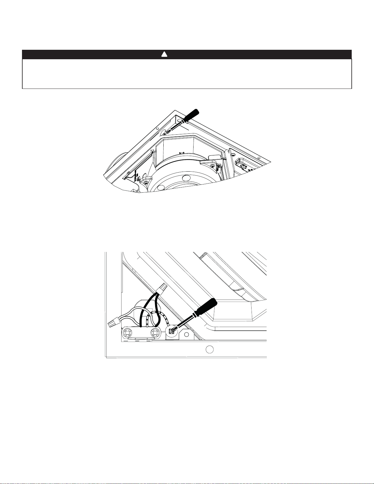
11
3 Instalación (cont.)
3.6 Conectar el cableado local (aparato ERVS100S-HW solamente)
1. Abra la puerta de la unidad.
2. Quitar y poner a un lado la tapa del compartimento elétrico.
3. Instalar la abrazadera de cable incluida con el kit y apretar para que los tornillos de la abrazadera sean accesibles. Insertar el
extremo del tubo flexible en el aparato, a través de la abrazadera de cable.
4. Conectar el hilo de tierra del tubo flexible al tornillo de tierra VERDE en el compartimiento eléctrico. Usando los capuchones
de conexión incluidos, realizar las conexiones como sigue: hilo NEGRO al hilo NEGRO, hilo BLANCO al hilo BLANCO.
VE0478
ADVERTENCIA
Riesgo de descarga eléctrica. El cableado eléctrico debe ser realizado por personal cualificado, de acuerdo con
todos los códigos y normas aplicables. Antes de conectar los hilos, apague la alimentación en el tablero de servicio
y bloquee los medios de desconexión para evitar que se conecte la corriente accidentalmente. La conexión con
cableado local necesita el uso de tubo flexible.
!
VE0479
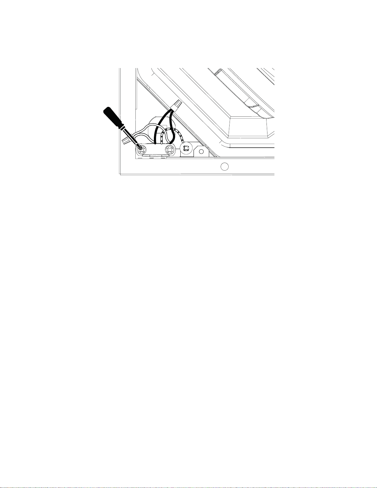
12
5. Sujetar el tubo de metal flexible a la abrazadera de cable incluida apretando los tornillos de cada lado de la abrazadera. No
apretar demasiado de manera que el tubo de metal flexible no sea dañado.
6. Insertar todos los hilos en el compartimiento eléctrico.
7. Reinstalar y sujetar la tapa del compartimento eléctrico, teniendo cuidado de no atascar ningún hilo. Reinstalar la puerta del
aparato.
8. Restablecer el encendido al panel de servicio.
3 Instalación (cont.)
3.6 Conectar el cableado local (aparato ERVS100S-HW solamente) (cont.)
VE0480
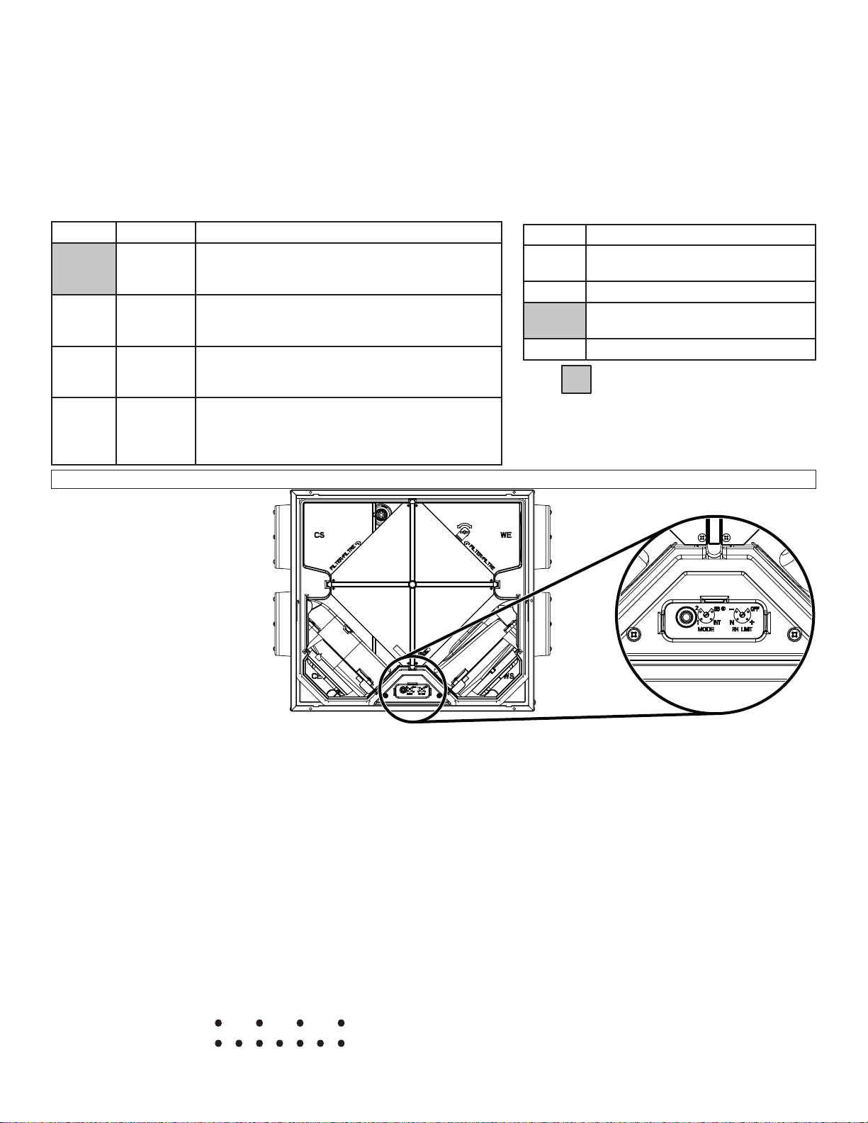
13
4.1.3 Elección de los parámetros adecuados
Modo:
• La unidad viene configurada de fábrica en el modo espera (SB) y debería reconfigurarse en el modo apropiado de acuerdo
con los códigos de construcción locales, la superficie de la vivienda, el número de personas que vivan en ella y las condiciones
meteorológicas locales.
Límite RH:
• La unidad viene configurada de fábrica en la posición "N" y normalmente debería permanecer en esta posición a menos que
las condiciones locales requieran algo diferente.
4.3 Secuencia de inicio
Cuando la unidad reciba corriente eléctrica, pasará por una secuencia de inicio en la que se probarán sus componentes.
La secuencia de inicio dura menos de un minuto y, tras ella, la luz LED parpadeará si hay algún problema. Si hay un control de 20
minutos VB20W de Broan conectado a la unidad, también parpadeará. La velocidad del parpadeo indica el tipo de problema:
Véase la sección Solución de problemas de esta guía para obtener instrucciones detalladas para solucionar el problema.
4.2 Preparación de la unidad
• Retire el cartón protector de la puerta, si procede.
• Verifique la orientación de la clapeta (véase la sección 3.1.2).
Parpadeo lento: Problema del sensor de humedad relativa y temperatura
Parpadeo rápido: problema de motor
4 Puesta en marcha de la unidad
4.1 Parámetros de la unidad
• El instalador debería cambiar los parámetros una vez terminados los trabajos de construcción con el fin de cumplir con los códigos
de construcción locales. Si el usuario desea cambiar los parámetros posteriormente, debería recurrir a un técnico autorizado.
• La unidad no debería funcionar nunca cuando el edificio esté en construcción.
• Todas las unidades vienen configuradas de fábrica en el modo espera y el límite de humedad relativa (RH) se ha colocado en la posición N.
• Ver la sección 3.3.2 para detalles específicos sobre el funcionamiento en invierno.
4.1.1 Descripción de los parámetros
4.1.2 Ubicación de los controles ajustables de modo y humedad relativa
VD0533
Parámetros
de fábrica
MODO (MODE) LíMITE RH (RH LIMIT)
POSICIÓN DESCRIPCIÓN
OFF
El límite de humedad relativa está
desactivado.
+ Límite de humedad relativa más alto.
N
Límite de humedad relativa
establecido en fábrica.
- Límite de humedad relativa más bajo.
POSICIÓN MODO DESCRIPCIÓN
SB Espera La unidad está apagada.
Se puede activar la unidad en alta velocidad
con el control de 20 minutos VB20W, si procede.
INT Intermitente La unidad funciona 20 minutos por hora en baja velocidad.
Se puede activar la unidad en alta velocidad
con el control de 20 minutos VB20W, si procede.
1 Baja
velocidad
La unidad funciona a 65 pi³/min.
Se puede activar la unidad en alta velocidad
con el control de 20 minutos VB20W, si procede.
2 Alta
velocidad
La unidad funciona a 105 pi³/min.
Se puede activar la unidad en alta velocidad con
el control de 20 minutos VB20W, si la unidad está
desactivada debido a la límite de humedad relativa.
Retire la puerta
para tener acceso
a los controles
ajustables de
modo (MODE) y
humedad relativa
(RH).
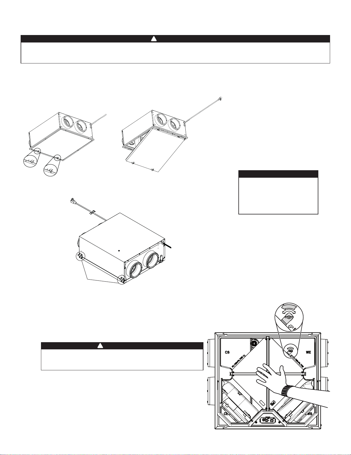
14
5 Mantenimiento
5.1 Mantenimiento trimestral
1. Desenchufe la unidad o corte la corriente en el tablero eléctrico.
2. Abra la puerta de la unidad siguiendo estas instrucciones y consultando las siguientes ilustraciónes:.
Riesgo de descarga eléctrica. Antes de cualquier trabajo de reparación o mantenimiento, corte la corriente siempre
en el tablero eléctrico o desenchufe la unidad de la toma de corriente. Al limpiar la unidad, se aconseja llevar
lentes y guantes de seguridad.
ADVERTENCIA
!
VO0274
3. Si la unidad está instalada en el techo o debajo del techo, sujete el
núcleo (), afloje la tuerca de aletas() y gire el soporte que retiene
el núcleo (parte sombreada de la ilustración de la derecha). Saque
el núcleo con sus filtros.
4. Lave ambos filtros del núcleo con agua tibia y un jabón suave.
Enjuáguelos y deje que sequen completamente antes de volver
a instalarlos en el núcleo. Consulte la etiqueta del núcleo para
colocarlo correctamente.
5. Introduzca el núcleo y los filtros limpios en la unidad. Consulte los
indicadores de posición de los filtros —que vienen en relieve dentro
de la unidad— para colocar correctamente el núcleo. Use el soporte
del núcleo y la tuerca de aletas para bloquear en su sitio el núcleo.
6. Cierre la puerta y vuelva a dar la corriente.
Si la unidad está instalada en el techo o debajo del techo,
sujete siempre el núcleo al girar el soporte que retiene el
núcleo; de no hacerlo, el núcleo podría caerse.
ADVERTENCIA
!
Tenga cuidado al abrir
la puerta; puede haber
agua cuando existe una
diferencia significativa entre
la temperatura interior y
exterior.
PRECAUCIÓN
CERRADURAS
ERVS100S-HW
Empuje las pestañas de
retención de la puerta para
retirarlas del cuadro de la
unidad.
Gire la puerta y retirarla.
ERVS100S-PC
Desbloquee cerraduras de ambos lados. Si se debe retirar la puerta para facilitar el
mantenimiento o si el espacio no es suficiente, retirar la tuerca en la cerradura y deslizar
la puerta lateralmente una vez la puerta ligeramente abierta.

15
5 Mantenimiento (cont.)
5.2 Mantenimiento anual
Siga las etapas 1 a 5 del mantenimiento trimestral y, a continuación, haga lo siguiente:
6. Use un aspirador dotado de un cepillo suave para retirar el polvo del núcleo de recuperación, el sensor y la clapeta (la
clapeta debe abrirse sin dificultades).
7. Introduzca el núcleo limpio y los filtros limpios en la unidad. Consulte los indicadores de posición de los filtros —que vienen
en relieve dentro de la unidad— para colocar correctamente el núcleo. Use el soporte del núcleo y la tuerca de aletas para
bloquear en su sitio el núcleo.
8. Cierre la puerta y vuelva a dar la corriente.
9. Limpie las bocas exteriores.
No moje el núcleo de recuperación. El núcleo de recuperación puede dañarse fácilmente, sobre todo si se
moja. El detergente puede dañar el sensor. Para limpiar el sensor, use sólo un trapo seco.
PRECAUCIÓN
6 Garantía
Este aparato de ventilación de Broan es un producto de gran calidad, fabricado y empacado con cuidado.
Broan garantiza al comprador original de sus productos que dichos productos están libres de defectos por el periodo de tiempo
indicado más adelante, a partir de la fecha de compra original. La garantía de todos los aparatos Broan cubre las piezas
únicamente contra cualquier defecto que pudiera perjudicar su funcionamiento. Su duración es de cinco (5) años. A reserva de que se
efectúe el mantenimiento del núcleo, tal y como se indica en la guía del usuario, el núcleo de recuperación de energía (ERV) tiene una
garantía de cinco (5) años. Si el aparato funcionara de manera inadecuada, consulte la guía del usuario.
Si el problema continúa, siga estos pasos:
PROCEDIMIENTO A SEGUIR
Si el aparato estuviera defectuoso, sírvase comunicar inmediatamente con su empresa de ventilación (véase la dirección en la cubierta
de este manual). La empresa determinará el origen del mal funcionamiento del aparato y lo sustituirá o reparará, de ser necesario.
Si le resultara imposible ponerse en comunicación con la empresa, telefonee (en América del Norte) al 1-800-558-1711 y nuestro
personal le indicará con mucho gusto el teléfono del distribuidor o del centro de servicio más próximo.
PIEZAS DE RECAMBIO Y SERVICIO
Para que el aparato funcione bien debe usar siempre piezas originales de Broan. Estas piezas se han diseñado especialmente para
cumplir con todas las normas de certificación de seguridad aplicables. El uso de piezas diferentes podría poner en peligro la seguri-
dad del aparato, ocasionar una reducción importante de su funcionamiento y producir una falla prematura.
Broan también aconseja consultar siempre con una empresa de servicios competente reconocida por Broan para las piezas de
recambio y para solicitar un servicio.
FACTURA
La garantía no cubrirá ninguna reparación ni sustitución sin la factura original de compra. Le rogamos, pues, que la conserve debidamente.
CONDICIONES Y LÍMITES
Este aparato es pensados únicamente para uso residencial y han de utilizarse en un edificio tal y como se describe a continuación:
Edificio: Toda construcción usada o destinada para ser usada con el fin de alojar o recibir personas, animales o cosas.
Uso residencial: Vivienda, alojamiento, suite: edificio o parte de un edificio que sirve o está destinado a servir de domicilio a una o varias
personas y que también posee instalaciones sanitarias, para preparar y consumir comidas y dormir. Local constituido
por una sola pieza o un grupo de piezas complementarias y ocupado por un inquilino o propietario; incluye los
alojamientos, las habitaciones individuales de moteles, hoteles, las casas de alquiler de habitaciones, los dormitorios
colectivos y las pensiones familiares, incluso las tiendas y los establecimientos de negocios de una sola pieza en una
vivienda.
Uso comercial: Establecimiento agrícola, comercial, de reunión, de cuidados o de detención: edificio o parte de un edificio que no
contenga viviendas, situado en un terreno dedicado a la agricultura o a la ganadería y usado fundamentalmente para
guardar equipos o animales, o para la producción, almacenamiento o tratamiento de productos agrícolas u hortícolas o la
alimentación de los animales. Edificio o parte de un edificio usado para colocar o vender mercancías o productos al por
menor o usado para realizar negocios o prestar servicios profesionales o personales. Edificio o parte de un edificio
usado por personas que se reúnen para realizar actividades cívicas, políticas, turísticas, religiosas, mundanas, educativas,
recreativas o similares, o para consumir alimentos o bebidas.Edificio o parte de un edificio que acoge a personas
que, por su estado físico o mental, necesitan cuidados o tratamientos médicos, o a personas que, por razones de
seguridad fuera de su control, no pueden guarecerse en caso de peligro.
Uso industrial: Edificio o parte de un edificio usado para ensamblar, fabricar, confeccionar, tratar, reparar o almacenar productos,
materias o materiales cuyo contenido es combustible y posee materias muy combustibles, inflamables o explosivas en
cantidad suficiente para constituir un riesgo concreto de incendio.
La garantía se aplicará en todos los casos en los que los daños no resulten de una instalación inadecuada, de un uso inapropiado, de un
abuso o negligencia, de un caso fortuito o de cualquier otra circunstancia fuera del control de Broan. Además, Broan no se hace responsable
de las lesiones o daños en la propiedad personal o inmobiliaria causados directa o indirectamente por el aparato de ventilación Broan.
Esta garantía anula todas las garantías anteriores.
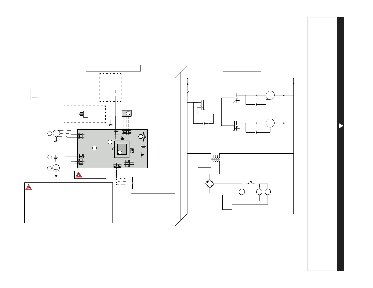
16
7 Diagrama de cableados
ADVERTENCIA
• Riesgo de descarga eléctrica. Antes de cualquier trabajo de reparación o mantenimiento, desconecte siempre el
aparato de su fuente de alimentación.
• Este producto está equipado con una protección contra la sobrecarga (fusible). Un fusible fundido indica que
se ha producido una sobrecarga o cortocircuito. Si el fusible se funde, desenchufe el aparato. Deje de utilizar el
aparato y póngase en contacto con el servicio de asistencia técnica.
!
LíNEA
NEUTRO
120 VAC
J1-1
J1-2
M
F1
DIAGRAMA LÓGICO
M
VELOCIDAD DEL
MOTOR
C2
MOTOR DEL VENTILADOR
DE INYECCIÓN M2
K2
K1
K3
J4-1
J4-2
J4-3
CONDENSADOR DEL MOTOR
DE
SALIDA SE AIRE
CONDENSADOR DEL MOTOR
DE INYECCIÓN
J3-1
J3-2
J3-3
J2-1 J2-2
T1
9.5 VAC
INTERRUPTOR DE PUERTA
INCORPORADO
S1
K2 K1 K3
CPU
DIAGRAMA DE CABLEADOS
CABLEADO DE TENSIÓN DE LÍNEA DE FÁBRICA
CABLEADO DE BAJA TENSIÓN DE FÁBRICA DE CLASE 2
CABLEADO DE BAJA TENSIÓN IN SITU DE CLASE 2
SENSOR RH
A2
S1
INTERRUPTOR DE
INTERBLOQUEO
DE
LA PUERTA
1
2
1
2
1
2
3
1
2
3
J4
J2
J3
A1
CONJUNTO
ELECTRÓNICO
F1
3A
T
IPO 3AG
1
2
J1
J6
1 2345
B
V
N
T1
J7
ICP
J9
4
3
2
1
J8
J5
1 234
OVERRIDE SWITCH
(OPTIONAL)
V
N
A
R
OC
OL
I
STB
M1
M2
C2
N
AZ
M
N
AZ
M
CÓDIGO DE COLORES
AMARILLO
AZUL
BLANCO
MARRÓN
A
AZ
B
M
NEGRO
ROJO
VERDE
N
R
V
Características
fundamentales
VE0477E
NOTAS
1. Protegido contra incendios por un fusible
certificado UL listed/CSA.
2. Si hay que sustituir alguno de los hilos originales, tal como
vienen de fábrica, use el mismo hilo equivalente.
3. El cableado in situ debe cumplir con los códigos,
ordenanzas y reglamentos aplicables.
4. Controles a distancia (circuito de clase 2) disponibles,
véase el manual de instrucciones.
5. El circuito del ventilador de la caldera sólo debe ser
un circuito de clase 2.
MOTOR DEL VENTILADOR
DE
SALIDA M1
ref: 24605_REV-A
-
+
~
~
120 VAC
60 Hz
B
N
V
120 VAC
60 Hz
Tierra
Línea
Neutro
ERVS100S-PC
ERVS100S-HW

17
8 Piezas de repuesto
SUSTITUCIÓN DE PIEZAS Y REPARACIÓN
Para que la unidad se conserve en buen estado, debe
usar repuestos genuinos Broan-NuTone LLC únicamente.
Estas piezas se han diseñado especialmente para cada
unidad y se han fabricado conforme a las normas de
certificación aplicables y un elevado nivel de seguridad.
El uso de repuestos de otros fabricantes podría causar
daños graves y reducir radicalmente el desempeño
de la unidad, causando así fallas prematuras. Broan-
NuTone LLC también aconseja ponerse en contacto con
un taller dereparación homologado por Broan-NuTone
LLC para todos los repuestos y reparaciones.
B
C
D
F
G
I
J
K
E
H
VL0083
N.o DESCRIPCIÓN N.o DE PIEZA CTD
1
PUERTA ERVS100S-HW SV66548 1
PUERTA ERVS100S-PC SV66549 1
2
PLACA DE CIRCUITOS IMPRESOS Y RESORTE DEL INTER-
RUPTOR (SOPORTE DE PLÁSTICO NO INCLUIDO)
SV62721 1
3 KIT DEL VENTILADOR IMPELENTE CE SV62724 1
4 KIT DEL VENTILADOR IMPELENTE WS SV62723 1
5 KIT METÁLICO DEL PUERTO AISLADO DE 6” SV62718 4
6 KIT DEL SISTEMA DE LA CLAPETA SV62717 1
7 SENSOR DE TEMPERATURA Y HUMEDAD RELATIVA SV62719 1
8
KIT DE FILTROS (2) SV21029 1
FILTROS OPCIONALES MERV 8 (2) V21030 1
9 NÚCLEO DE RECUPERACIÓN DE ENERGíA ERV SV61223 1
10 CONDENSADOR DE BAJA VELOCIDAD 18 µF SV62722 1
* KIT DEL DISPOSITIVO DE BLOQUEO DEL NÚCLEO SV61237 1
* KIT DE PIEZAS SV22079 1
* NO SE MUESTRA.
PUERTA DEL ERVS100S-HW
MOSTRADA

18
9 Solución de problemas
Si el aparato no funciona debidamente, desenchúfelo durante un minuto y vuélvalo a enchufar para reiniciarlo. Si sigue sin
funcionar debidamente, consulte la tabla de abajo.
PROBLEMAS CAUSAS POSIBLES INTENTE ESTO
1
La unidad no se
pone en marcha.
• No hay corriente en la toma.
• La puerta de la unidad no está bien
cerrada.
• Pestañas de bloqueo del soporte de
plástico del PCB este desengancha.
• Verifique el disyuntor en el tablero de distribución.
• ERVS100S-PC únicamente: Pruebe la toma de corriente con otro aparato eléctrico
(p. ej., una lámpara). Si sigue sin funcionar, llame a un electricista.
• ERVS100S-HW únicamente: Controlar con un voltímetro los cables de alimentación.
Si no se detecta tensión, llamar a un electricista.
• Compruebe que la puerta de la unidad está bien cerrada.
• Compruebe que las pestañas de bloqueo del soporte de plástico del PCB este
engancha correctamente.
2
La señal LED
parpadea
rápidamente en el
botón pulsador y
en la unidad (error
del motor).
• Arnés del motor dañado o mal
conectado.
• Placa de circuitos impresos,
conjunto del motor o condensador
de baja velocidad defectuoso.
• Verifique ambas conexiones del arnés del motor, compruebe que los conectores
estén conectados en los lugares adecuados, que los hilos no estén dañados y que
las clavijas de los conectores no estén corroídas.
• Abra la puerta y presione el resorte del interruptor de la puerta para reiniciar la
unidad activando el proceso de autocomprobación de la secuencia de inicio.
Ambos motores deben ponerse en marcha a alta velocidad durante 10 segundos
y pasar luego a baja velocidad durante 10 segundos. Si no se ponen en marcha
los dos motores a alta velocidad, sustituya la placa de circuitos impresos.
• Si uno de los motores no se pone en marcha a alta velocidad, invierta la conexión
de ambos motores y vuelva a iniciar el proceso de autocomprobación; si el motor
sigue sin ponerse en marcha a alta velocidad, sustituya el conjunto del motor. Si
el problema es ahora el otro motor, sustituya la placa de circuitos impresos.
• Si ambos motores funcionan a alta velocidad pero no a baja velocidad, sustituya
el condensador de baja velocidad. Si sólo funciona un motor a baja velocidad,
sustituya el conjunto del motor defectuoso.
3
La señal LED
parpadea
lentamente en el
botón pulsador y
en la unidad (error
del sensor de
humedad relativa y
temperatura).
• Sensor de humedad relativa y
temperatura mal conectado.
• Sensor de humedad relativa y
temperatura defectuoso.
• Verifique la conexión del arnés del sensor, compruebe que el conector esté
conectado en el lugar adecuado, que los hilos no estén dañados y que las clavijas
del conector no estén corroídas.
• Abra la puerta y presione el resorte del interruptor de la puerta para reiniciar
la unidad activando el proceso de autocomprobación de la secuencia de inicio.
Ambos motores deben ponerse en marcha a alta velocidad durante 10 segundos
y pasar luego a baja velocidad durante 10 segundos. Tras esto, la unidad probará
su sensor de temperatura y humedad relativa. Si la señal LED sigue parpadeando
lentamente, sustituya el sensor de temperatura y humedad relativa defectuoso.
4
El control mural no
funciona.
• La unidad no es compatible con el
control.
• Los hilos pueden estar en posiciones
invertidas.
• Los hilos pueden estar mal
conectados.
• Los hilos pueden estar rotos.
• Control mural defectuoso.
• Consulte la tabla de la página 2 para ver la compatibilidad de los controles.
• Compruebe que los hilos con códigos de colores han sido conectados en los
lugares adecuados.
• Compruebe que los hilos estén bien conectados.
• Examine cada hilo y sustituya los que estén dañados. Si los hilos están escondidos
en las paredes, pruebe el control usando un hilo más corto.
• Sustituya el control mural.
5
La unidad deja
entrar
demasiada
humedad en el
edificio durante la
ventilación.
• Mal funcionamiento de la clapeta
de retención.
• Mala configuración del límite de
humedad relativa.
• Verifique si la clapeta de retención de la unidad está cerrada cuando la unidad
está apagada; si no lo está, verifique la orientación del conjunto de la clapeta
(la palabra “TOP” grabada en el soporte de la clapeta debe estar en la parte de
arriba), verifique si el imán está en su lugar en el soporte de la clapeta, verifique si
el clip metálico está en su lugar en la clapeta. La clapeta debe abrir sin dificultades.
• Verifique el ajuste del límite de humedad relativa (la configuración de
fábrica es “N” para el clima del sur y húmedo); ajuste el límite de humedad
relativa colocándolo en la posición “-” para reducir el límite de humedad
de la ventilación. La velocidad de ventilación se puede reducir cambiando el
modo, de forma que entre menos humedad en el edificio.
6
La unidad deja
de ventilar con
demasiada
frecuencia.
• Mala configuración del límite de
humedad relativa.
• Verifique el ajuste del límite de humedad relativa (la configuración de fábrica
es “N” para el clima del sur y húmedo); ajuste el límite de humedad relativa
colocándolo en la posición “+” para incrementar el límite de humedad de la
ventilación (el tiempo de ventilación será mayor) o ponga el límite de humedad
relativa en la posición “OFF” para desactivar el sensor.
ADVERTENCIA
!
Riesgo de descarga eléctrica. Las conexiones de la tarjeta electrónica sólo deben verificarse por personal cualificado.