Loading ...
When recessing into the ceiling
WARNING:
• Before installing, confirm that the locations where the unit and the safety wire are to be installed are strong enough.
• Attach the unit to the ceiling by using the included brackets. Before installing, confirm that the mounting location is strong
enough. In addition, make sure that the ceiling panel will not be subjected to a load higher than the withstand load, such as by
using the included U-shaped bracket to transfer the load onto structural material. If a load will be applied to the panel,
reinforce the panel as necessary in order to prevent parts from being damaged and the unit or parts from falling.
NOTICE:
• To supply power, confirm that the unit is securely installed, and then connect the LAN cable to a PoE injector or PoE network switch that
complies with IEEE802.3af.
• Cables up to a maximum length of 100 m can be used.
• In order to prevent electromagnetic interference, use STP (shielded twisted pair) cables.
• The weight, including the grille and mounting brackets, is approximately 6.8 kg.
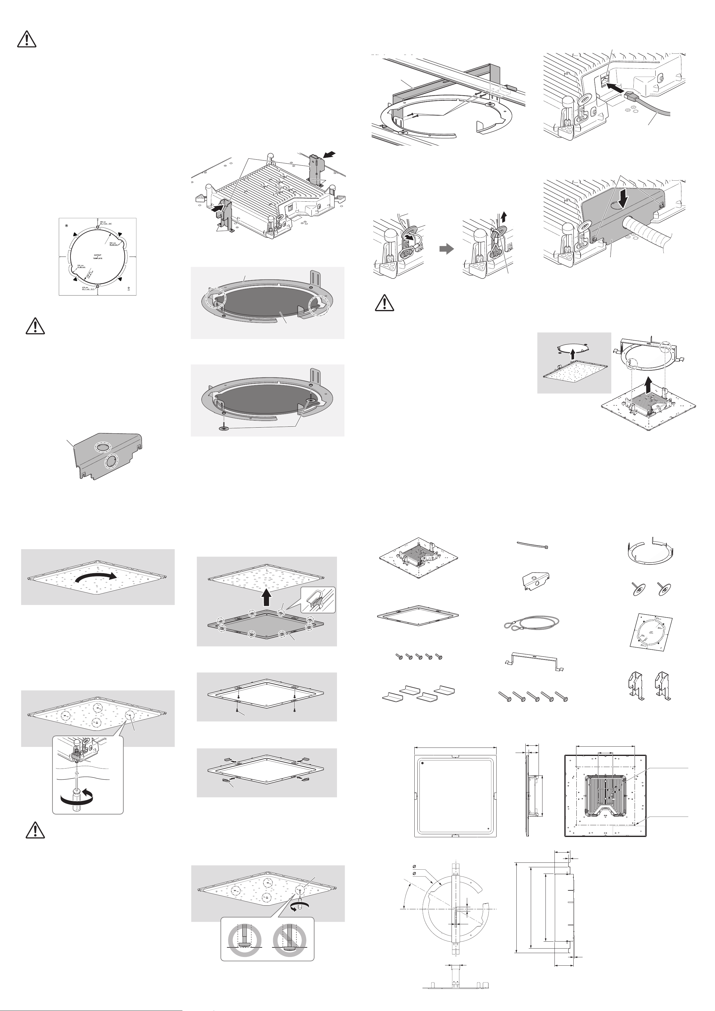
1 Making a hole in the ceiling
1. Position the cutout template on the ceiling, and then
mark the cutout locations.
Determine the location and orientation based on the position
of the logo.
The thick lines indicate parts that are to be cut out.
NOTE:
When using a hole cutter, mark the center points of the five
holes to be cut according to the cutout template. First cut the
R35 mm holes.
Make sure that there will be ceiling rails on the top and bottom
sides of the cutout template when it is oriented as shown below.
2. Cut holes in the ceiling along the markings.
CAUTION:
Be careful not to get debris or dust in your eyes
when cutting holes.
2 Attaching the brackets
If the terminal cover will not be used, skip steps 1, 8 and
10
.
However, the dustproofness and plenum ratings will not be met.
1. Make a hole in the terminal cover to pass the conduit
through.
Make a cable hole in the terminal cover according to the
orientation of the conduit. The cable hole can be made in the
terminal cover horizontally or vertically.
We recommend using nippers. The terminal cover may
become deformed if you try to make the hole by hitting or
prying the cover with a flathead screwdriver, etc.
2. After loosening the temporary mounting brackets
screws on the unit, attach the temporary mounting
brackets to the unit by using those screws.
3. Insert the C-ring into the hole in the ceiling, and
align the notches.
4. Secure the C-ring to the ceiling by using the
mounting screws for the C-ring.
Terminal cover
Temporary
mounting bracket
Screws
Screws
C-ring
Ceiling
Hole
Ceiling
Mounting screw for C-ring
5. Insert the U-shaped bracket into the hole in the
ceiling, and then secure it to the C-ring by using the
mounting screws for the U-shaped bracket.
To spread the weight of the unit, make sure that both ends of
the U-shaped bracket rest on a ceiling rail.
6. Attach the safety wire to a structure above the
ceiling.
7. Attach the safety wire to the safety wire ring, and
secure the safety wire and safety wire ring with a
cable tie.
Perform the following steps up to step 3 with the unit
hanging from the safety wire.
WARNING:
Be sure to take measures to prevent the unit from
falling.
If the attached safety wire is not long enough,
consider the weight of the unit and the installation
location when preparing a wire of appropriate length
and strength. If the wire is too long, kinetic energy
will be applied to the wire when the unit falls,
possibly causing the wire to break and the unit to fall.
8. Pass the LAN cable through the terminal cover.
9. Plug the LAN cable into the [Dante/PoE] port.
10.
After loosening the terminal cover screws on the unit,
attach the terminal cover to the unit by using those
screws.
3 Attaching to the ceiling
1. Align the temporary mounting brackets with the
notches of the hole in the ceiling, and then slowly
insert the unit through the ceiling.
Be careful not to pinch the cable or safety wire between the
ceiling and the unit.
Mounting screw
for U-shaped
bracket
U-shaped bracket
Safety wire
Safety
wire ring
Cable tie
LAN cable
[Dante/PoE] port
Terminal cover
Screws
2. Turn the unit clockwise to adjust its orientation.
Placing the temporary mounting brackets on the C-ring allows
you to take your hands off the unit to work.
3. While holding the unit up, turn the four mounting
screws clockwise with a Phillips screwdriver to
tighten them.
The first turn opens the clamp. Each turn of the screw lowers
the clamp and holds the C-ring against the ceiling.
If it is difficult to open the clamp, turn the screw
counterclockwise half a turn to make it easier for the clamp to
open.
The orientation of the unit may shift when the mounting screws
are turned. If the unit becomes misaligned, correct its position
before fully tightening the screws.
WARNING:
• Do not overtighten the mounting screws, otherwise
they or the clamp may break.
• Do not turn any screws other than the mounting
screws. Otherwise, the unit may fall or malfunction.
4 Attaching the grille
1. Attach the grille to the unit.
Attach while lightly opening the 8 hooks on the grille outward.
2. Secure the grille at four locations by using its
mounting screws.
3. Slide the four screw covers from the side so they fit
in their positions.
For removal, reverse the procedure. In that case, note the following.
• When removing the grille, lightly open the hooks outward.
• Loosen the four mounting screws by turning them
counterclockwise. When the screw is loosened, the clamp that
holds the unit against the ceiling will rise and close in. Make sure
that the screw head does not protrude from the surface. If the
screw is loosened too much, the clamp will come off, possibly
falling and causing injuries when the unit is being removed from
the hole.
Mounting screw
Clamp
Grille
Hook
Mounting screw for grille
Screw cover
Mounting screw
Bundled items
Dimensions
Ceiling Microphone (1)
Grille (1)
Mounting screw for grille (M3×8 mm) (5)
Screw cover (4)
Safety wire (1)
Mounting screw for U-shaped bracket (M4×20 mm) (5)
U-shaped bracket (1)
C-ring (1)
Mounting screw for C-ring (2)
Cutout template (1)
Cable tie (1)
Terminal cover (1)
Temporary mounting bracket (2)
□
560
□
400
□
100
□
280
90
6822
111
13
642 578 479
388
470
30°
57.2
30
11
100–135
5
Unit: mm
4 × M4 × 0.75
DEPTH 10 max.
4 × M6 × 1.0
DEPTH 13 max.
Manual Development Group
© 2020 Yamaha Corporation
Published 12/2020
IPES-C0