Q 15
Q 15-L
Q 15-P
TWO-WAY POINT SOURCE MODULES
OWNER’S MANUAL
MANUALE UTENTE


3
CONTENTS
ENGLISH
1 SAFETY PRECAUTIONS AND GENERAL INFORMATION ................................................................................................................. 4
2 DESCRIPTION .................................................................................................................................................................................... 6
3 CONNECTIONS .................................................................................................................................................................................. 7
4 HORIZONTAL HANGING ................................................................................................................................................................... 9
4.1 HORIZONTAL HANGING OF 1 SPEAKER .................................................................................................................................................9
4.2 HORIZONTAL HANGING OF 2 OR MORE SPEAKERS .............................................................................................................................10
4.3 HORIZONTAL CONFIGURATIONS .........................................................................................................................................................12
5 VERTICAL HANGING ....................................................................................................................................................................... 14
5.1 VERTICAL CONFIGURATIONS ...............................................................................................................................................................16
6 VERTICAL HANGING WITH A 10° ANGLE ...................................................................................................................................... 18
7 EXAMPLES OF MIXED CONFIGURATIONS .................................................................................................................................... 20
ITALIANO
1 AVVERTENZE PER LA SICUREZZA E INFORMAZIONI GENERALI ................................................................................................. 22
2 DESCRIZIONE .................................................................................................................................................................................. 24
3 COLLEGAMENTI .............................................................................................................................................................................. 25
4 SOSPENSIONE ORIZZONTALE ........................................................................................................................................................ 27
4.1 SOSPENSIONE ORIZZONTALE DI 1 DIFFUSORE .....................................................................................................................................27
4.2 SOSPENSIONE ORIZZONTALE DI 2 DIFFUSORI ......................................................................................................................................28
4.3 CONFIGURAZIONI ORIZZONTALI .........................................................................................................................................................30
5 SOSPENSIONE VERTICALE .............................................................................................................................................................. 32
5.1 CONFIGURAZIONI VERTICALI...............................................................................................................................................................34
6 SOSPENSIONE VERTICALE CON ANGOLO DI 10° ......................................................................................................................... 34
7 ESEMPI DI CONFIGURAZIONI MISTE ............................................................................................................................................ 38
DIMENSIONS .............................................................................................................................................................................................. 40
SPECIFICATIONS ........................................................................................................................................................................................ 41
4
EN
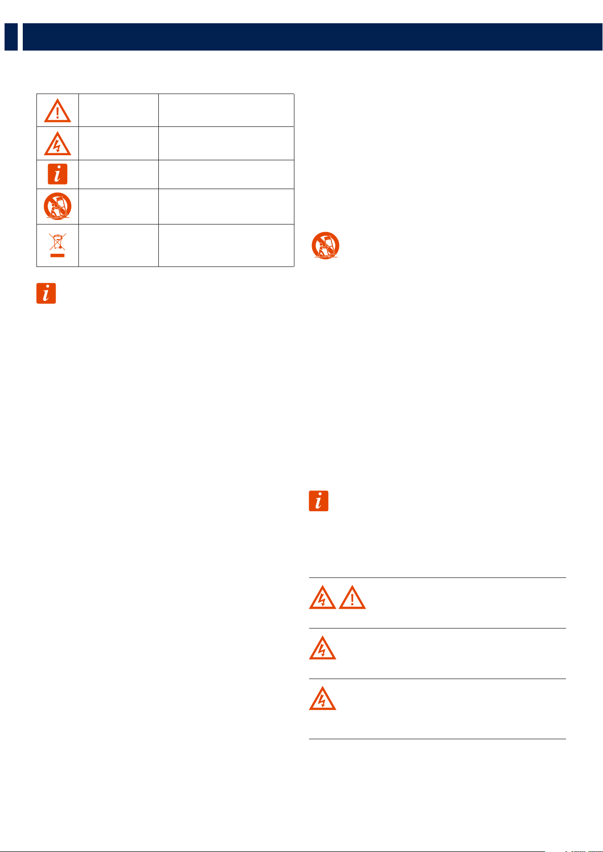
The symbols used in this document give notice of important operating instructions and
warnings which must be strictly followed.
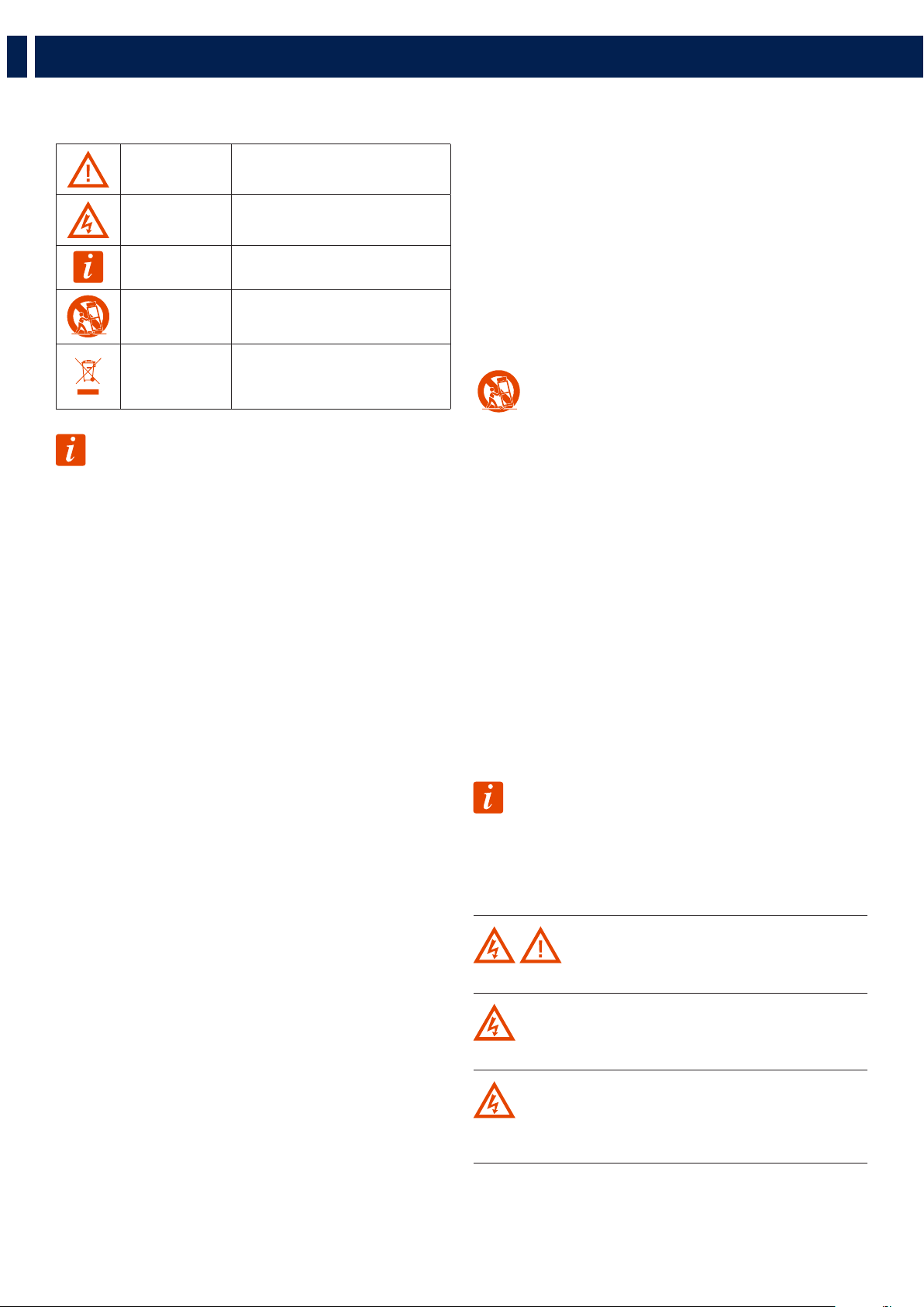
CAUTION
Important operating instructions: explains
hazards that could damage a product,
including data loss
WARNING
Important advice concerning the use of
dangerous voltages and the potential risk of
electric shock, personal injury or death.
IMPORTANT NOTES
Helpful and relevant information
about the topic
SUPPORTS, TROLLEYS
AND CARTS
Information about the use of supports,
trolleys and carts. Reminds to move with
extreme caution and never tilt.
WASTE DISPOSAL
This symbol indicates that this product
should not be disposed with your household
waste, according to the WEEE directive
(2012/19/EU) and your national law.
IMPORTANT NOTES
This manual contains important information about the correct and safe use of the device.
Before connecting and using this product, please read this instruction manual carefully and
keep it on hand for future reference. The manual is to be considered an integral part of
this product and must accompany it when it changes ownership as a reference for correct
installation and use as well as for the safety precautions. RCF S.p.A. will not assume any
responsibility for the incorrect installation and / or use of this product.
SAFETY PRECAUTIONS
1. All the precautions, in particular the safety ones, must be read with special attention, as
they provide important information.
2. Power supply from mains
a. The mains voltage is sufficiently high to involve a risk of electrocution; install and
connect this product before plugging it in.
b. Before powering up, make sure that all the connections have been made correctly and
the voltage of your mains corresponds to the voltage shown on the rating plate on the
unit, if not, please contact your RCF dealer.
c. The metallic parts of the unit are earthed through the power cable. An apparatus with
CLASS I construction shall be connected to a mains socket outlet with a protective
earthing connection.
d. Protect the power cable from damage; make sure it is positioned in a way that it cannot
be stepped on or crushed by objects.
e. To prevent the risk of electric shock, never open this product: there are no parts inside
that the user needs to access.
f. Be careful: in the case of a product supplied by manufacturer only with POWERCON
connectors and without a power cord, jointly to POWERCON connectors type NAC3FCA
(power-in) and NAC3FCB (power-out), the following power cords compliant to national
standard shall be used:
- EU: cord type H05VV-F 3G 3x2.5 mm2 - Standard IEC 60227-1
- JP: cord type VCTF 3x2 mm2; 15Amp/120V~ - Standard JIS C3306
- US: cord type SJT/SJTO 3x14 AWG; 15Amp/125V~ - Standard ANSI/UL 62
3. Make sure that no objects or liquids can get into this product, as this may cause a short
circuit. This apparatus shall not be exposed to dripping or splashing. No objects filled with
liquid, such as vases, shall be placed on this apparatus. No naked sources (such as lighted
candles) should be placed on this apparatus.
4. Never attempt to carry out any operations, modifications or repairs that are not expressly
described in this manual.
Contact your authorized service centre or qualified personnel should any of the following
occur:
- The product does not function (or functions in an anomalous way).
- The power cable has been damaged.
- Objects or liquids have got in the unit.
- The product has been subject to a heavy impact.
5. If this product is not used for a long period, disconnect the power cable.
6. If this product begins emitting any strange odours or smoke, switch it off immediately
and disconnect the power cable.
7. Do not connect this product to any equipment or accessories not foreseen.
For suspended installation, only use the dedicated anchoring points and do not try to hang
this product by using elements that are unsuitable or not specific for this purpose. Also
check the suitability of the support surface to which the product is anchored (wall, ceiling,
structure, etc.), and the components used for attachment (screw anchors, screws, brackets
not supplied by RCF etc.), which must guarantee the security of the system / installation
over time, also considering, for example, the mechanical vibrations normally generated by
transducers.
To prevent the risk of falling equipment, do not stack multiple units of this product unless
this possibility is specified in the user manual.
8. RCF S.p.A. strongly recommends this product is only installed by professional
qualified installers (or specialised firms) who can ensure correct installation
and certify it according to the regulations in force.
The entire audio system must comply with the current standards and
regulations regarding electrical systems.
9. Supports, trolleys and carts.
The equipment should be only used on supports, trolleys and carts, where
necessary, that are recommended by the manufacturer. The equipment /
support / trolley / cart assembly must be moved with extreme caution. Sudden
stops, excessive pushing force and uneven floors may cause the assembly to
overturn. Never tilt the assembly.
10. There are numerous mechanical and electrical factors to be considered when installing
a professional audio system (in addition to those which are strictly acoustic, such as sound
pressure, angles of coverage, frequency response, etc.).
11. Hearing loss.
Exposure to high sound levels can cause permanent hearing loss. The acoustic pressure level
that leads to hearing loss is different from person to person and depends on the duration
of exposure. To prevent potentially dangerous exposure to high levels of acoustic pressure,
anyone who is exposed to these levels should use adequate protection devices. When a
transducer capable of producing high sound levels is being used, it is therefore necessary
to wear ear plugs or protective earphones. See the manual technical specifications to know
the maximum sound pressure level.
OPERATING PRECAUTIONS
- Place this product far from any heat sources and always ensure an adequate air
circulation around it.
- Do not overload this product for a long time.
- Never force the control elements (keys, knobs, etc.).
- Do not use solvents, alcohol, benzene or other volatile substances for cleaning the
external parts of this product.
IMPORTANT NOTES
To prevent the occurrence of noise on line signal cables, use screened cables only and avoid
putting them close to:
- Equipment that produces high-intensity electromagnetic fields
- Power cables
- Loudspeaker lines
WARNING! CAUTION! To prevent the risk of fire or electric
shock, never expose this product to rain or humidity.
WARNING! To prevent electric shock hazard, do not connect to
mains power supply while grille is removed
WARNING! to reduce the risk of electric shock, do not disassemble
this product unless you are qualified. Refer servicing to qualified service
personnel.
1. SAFETY PRECAUTIONS AND GENERAL INFORMATION
5
EN
1. SAFETY PRECAUTIONS AND GENERAL INFORMATION
CORRECT DISPOSAL OF THIS PRODUCT
This product should be handed over to an authorized collection site for
recycling waste electrical and electronic equipment (EEE). Improper
handling of this type of waste could have a possible negative impact on
the environment and human health due to potentially hazardous
substances
that are generally associated with EEE. At the same time, your cooperation in
the correct disposal of thisproduct will contribute to the effective usage of
natural resources. For more information about where you can drop off your
waste equipment for recycling, please contact your local city office, waste
authority or your household waste disposal service.
CARE AND MAINTENANCE
To ensure a long-life service, this product should be used following these advices:
- If the product is intended to be set up outdoors, be sure it is under cover and protected
to rain and moisture.
- If the product needs to be used in a cold environment, slowly warm up the voice coils
by sending a low-level signal for about 15 minutes before sending high-power signals.
- Always use a dry cloth to clean the exterior surfaces of the speaker and always do it
when the power is turned off.
CAUTION: to avoid damaging the exterior finishes do not use
cleaning solvents or abrasives.
WARNING! CAUTION! For powered speakers, do cleaning
only when the power is turned off.
6
EN
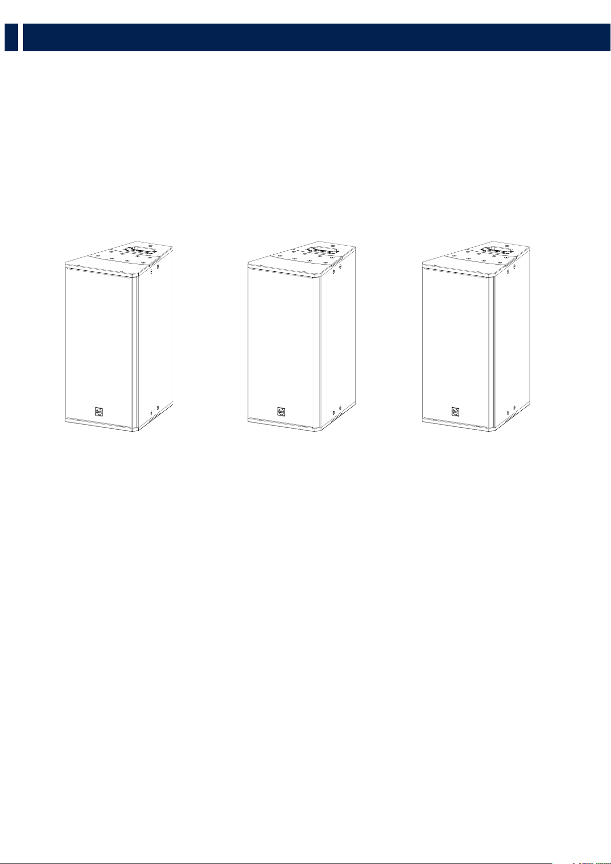
Q 15, Q 15-L, Q 15-P - TWO-WAY POINT SOURCE MODULES
Q 15 speakers are two-way, bi-amp point source modules for mid distance and long throw applications, merging a compact size with a very high
output and accurate voice and sound reproduction. The systems are equipped with the latest generation of RCF precision transducers: a 15”
neodymium woofer (4.0” v.c.) and a 1.4” exit compression driver (4.0” v.c.) providing 1500 W power rating.
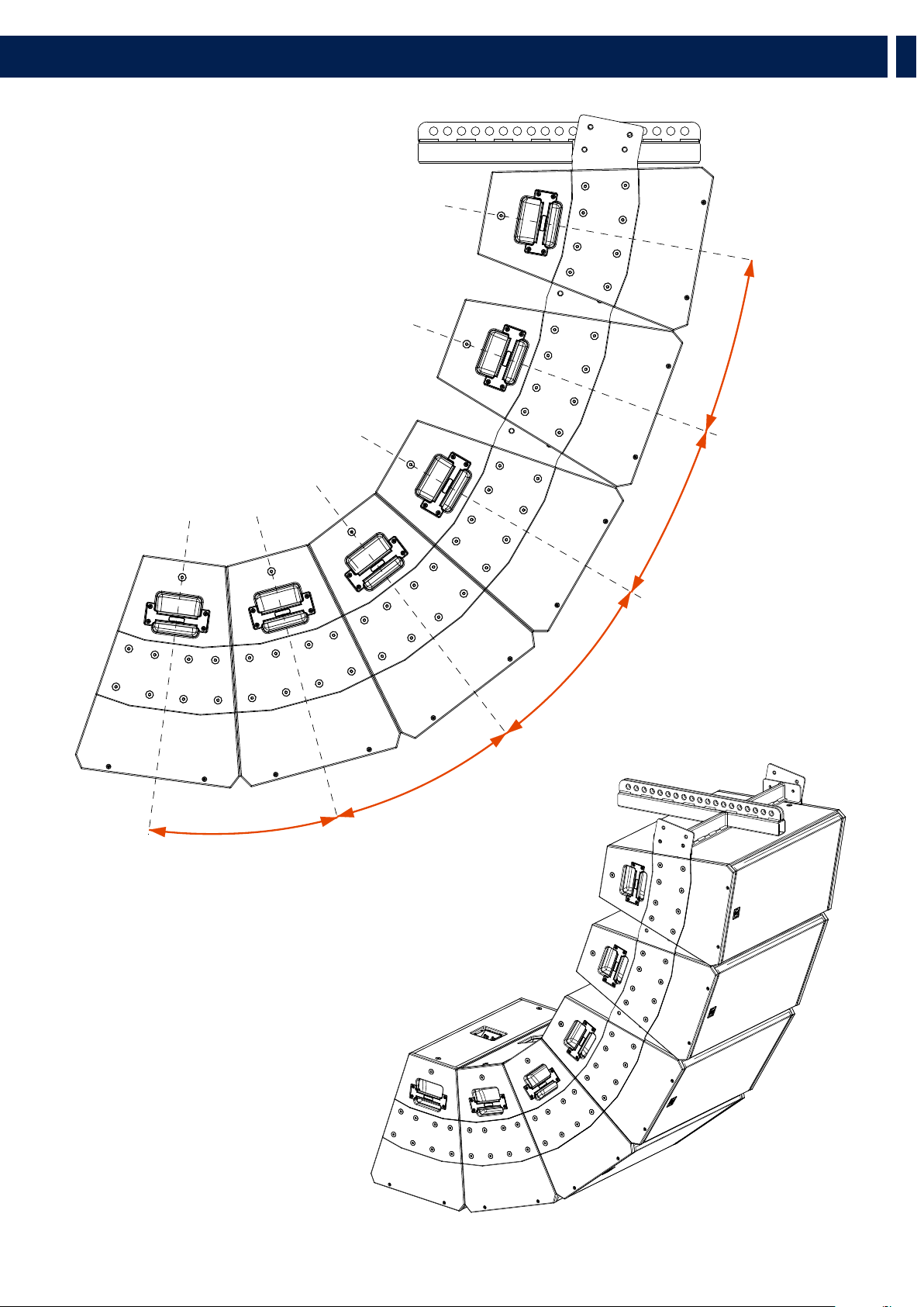
Directivity, horizontal 22.5° and vertical 60° (Q 15), 90° (Q 15-L), 40° (Q 15-P) makes Q 15 speakers ideal to be used in point source configuration
for mid distance applications or clustered with narrower angles for long throw applications. The enclosure shape is trapezoidal and offers a 22.5°
coupling angle each side. Thanks to two different fly bars, it can be clustered both horizontally (up to 4 modules with the same fly bar) and
vertically (up to 6 modules with one flybar and up to 8 modules with two fly-bars). Connections to the amplifier are made through Speakon multi-
pole connectors. The grille is in custom perforated steel epoxy coated, with woven fabric backing. The cabinet is made of multi-ply Baltic birch
plywood and finished in a very resistant polyurea black paint.
2. DESCRIPTION
Q 15
Horizontal directivity: 22.5°
Vertical directivity: 60°
Q 15-L
Horizontal directivity: 22.5°
Vertical directivity: 90°
Q 15-P
Horizontal directivity: 22.5°
Vertical directivity: 40°

7
EN
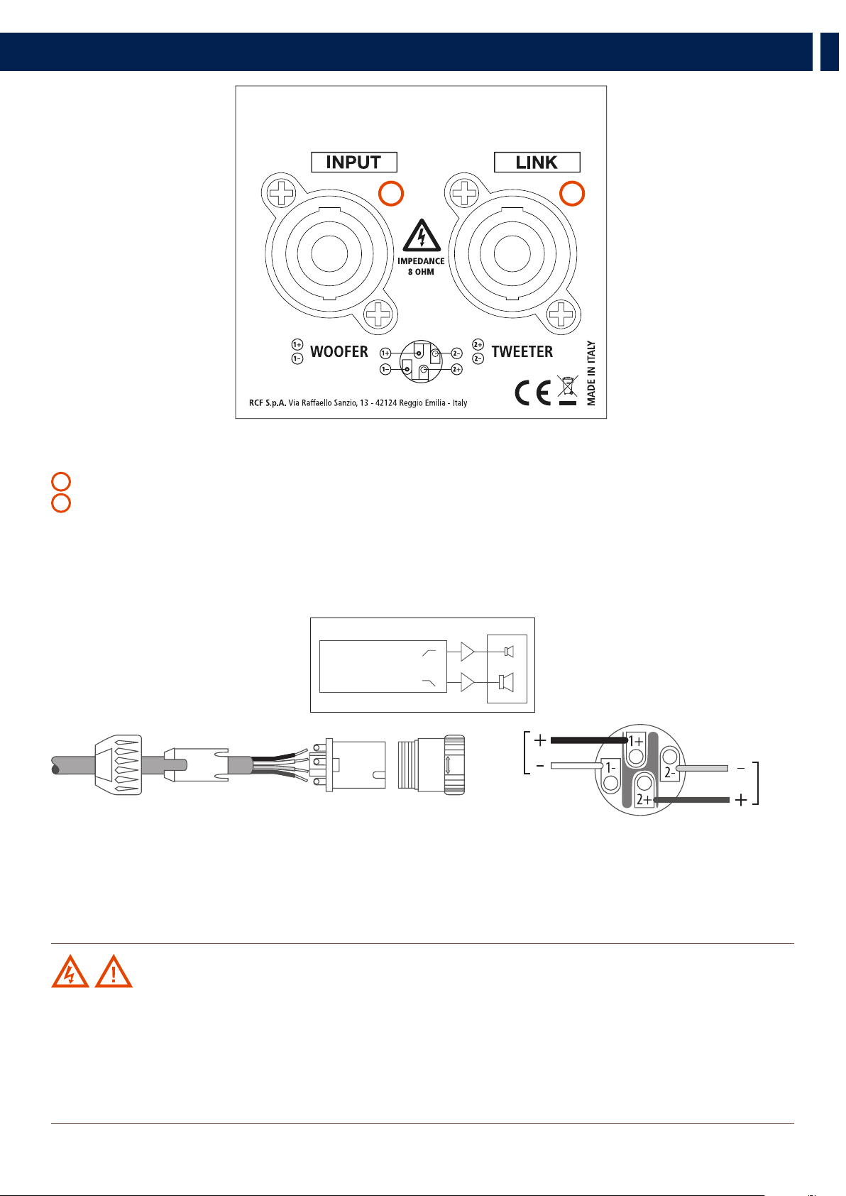
THE REAR PANEL
The rear panel displays 2 sockets, both for ‘Neutrik Speakon NL4’ (4-pole) plugs:
1
The INPUT socket receives the signal from the amplifier
2
The LINK socket can be used to link another speaker
‘BI-AMP’ MODE
The speaker must be powered by two amplifiers (one for the low frequency, one for the high frequency) and an external crossover is required.
Check in the specification table the impedance of both ways, their power and the suggested crossover frequency.
LOW
HIGH
AMP.
CROSSOVER
AMP.
CONNECTIONS
- Low frequency amplifier + output to the pin 1+ of the SPEAKON connector
- Low frequency amplifier - output to the pin 1- of the SPEAKON connector
- High frequency amplifier + output to the pin 2+ of the SPEAKON connector
- High frequency amplifier - output to the pin 2- of the SPEAKON connector
WARNING! CAUTION! Loudspeaker connections should be only made by qualified and experienced personnel
having the technical know-how or enough specific instructions (to ensure that connections are made correctly) in order to
prevent any electrical danger.
To prevent any risk of electric shock, do not connect loudspeakers when the amplifier is switched on.
Before turning the system on, check all connections and make sure there are no accidental short circuits.
The entire sound system shall be designed and installed in compliance with the current local laws and regulations regarding
electrical systems.
3. CONNECTIONS
21
8
EN
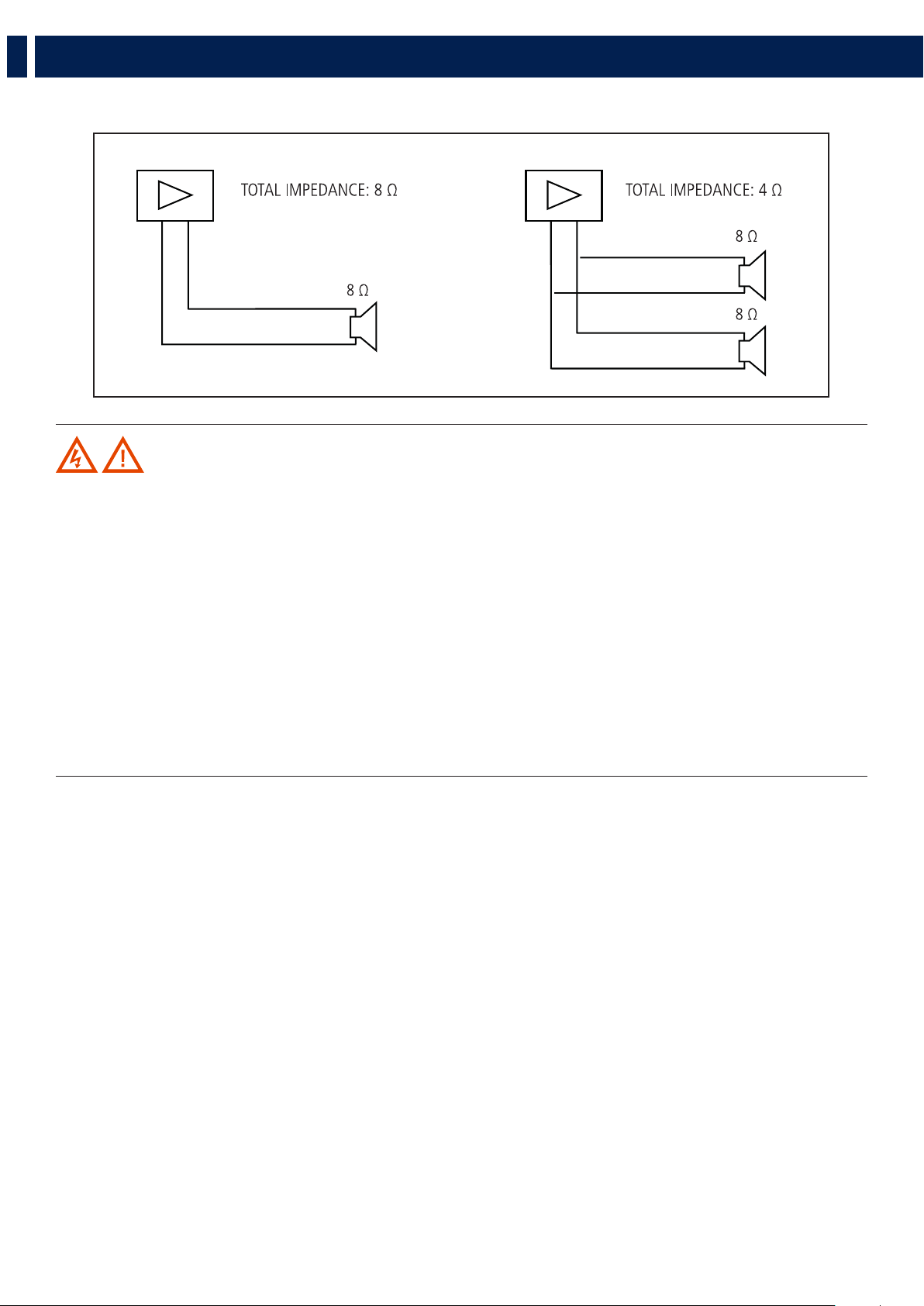
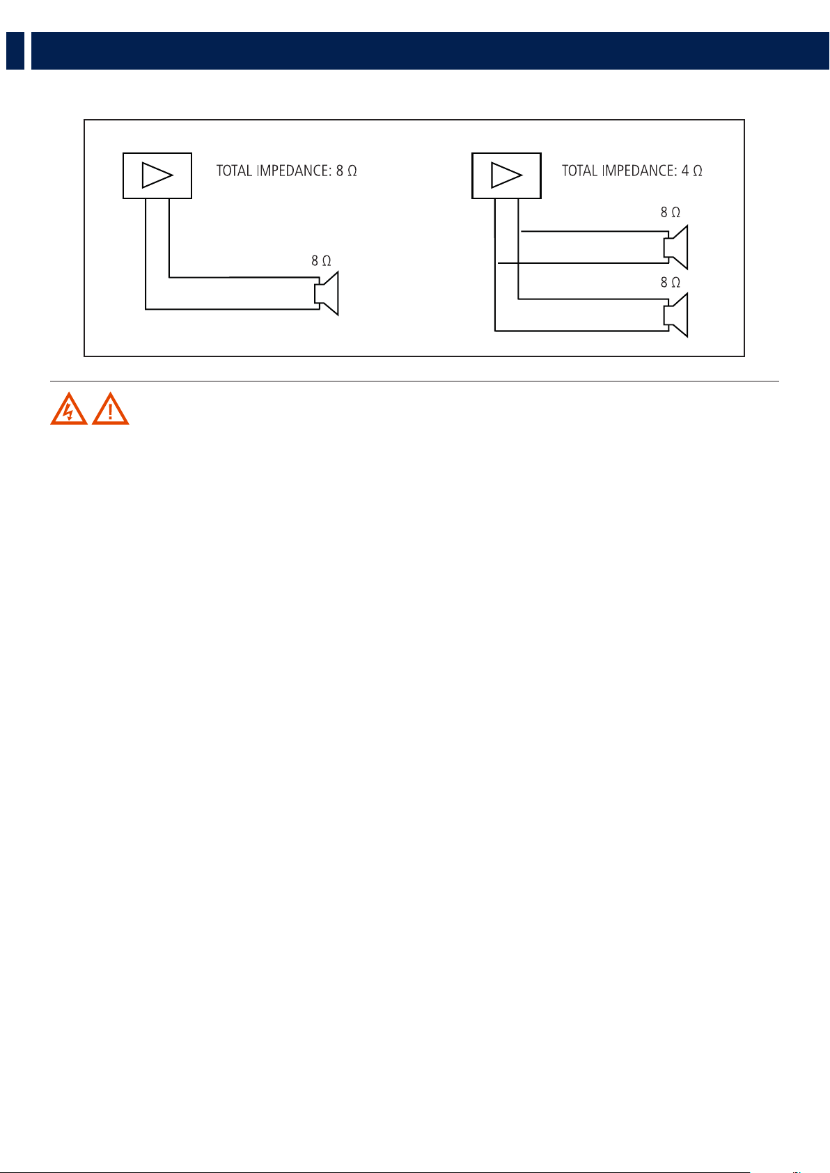
NOTES ABOUT LOW IMPEDANCE CONNECTIONS
-+
+
+
-+
+
WARNING! CAUTION!
- The total loudspeaker impedance must not be lower than the amplifier output impedance. Note: a loudspeaker total
impedance equal to the amplifier output one permits to get the maximum deliverable power (but an higher loudspeaker
impedance entails less power).
- The total loudspeaker power shall be adequate for the maximum deliverable power of the amplifier.
- The loudspeaker line shall be short (for long distances, it may be necessary to use cables with large cross-section wires).
- Always use cables having wires with an adequate cross-section, considering the cable length and the total loudspeaker
power.
- Loudspeaker lines must be kept separated from the mains cables, microphone cables or others, in order to avoid inductive
phenomena may cause hum or noises.
- Use loudspeaker cables with twisted wires to reduce hum caused by inductive effects due to coupling with electromagnetic
fields.
- Do NOT connect the low impedance input directly to 70 / 100 V constant voltage lines.
3. CONNECTIONS

9
EN
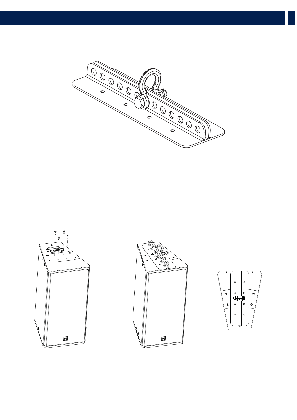
4. HORIZONTAL HANGING
Up to 4 x Q 15 can be hanged horizontally by using the horizontal flybar FLY BAR FL-B H Q 15.
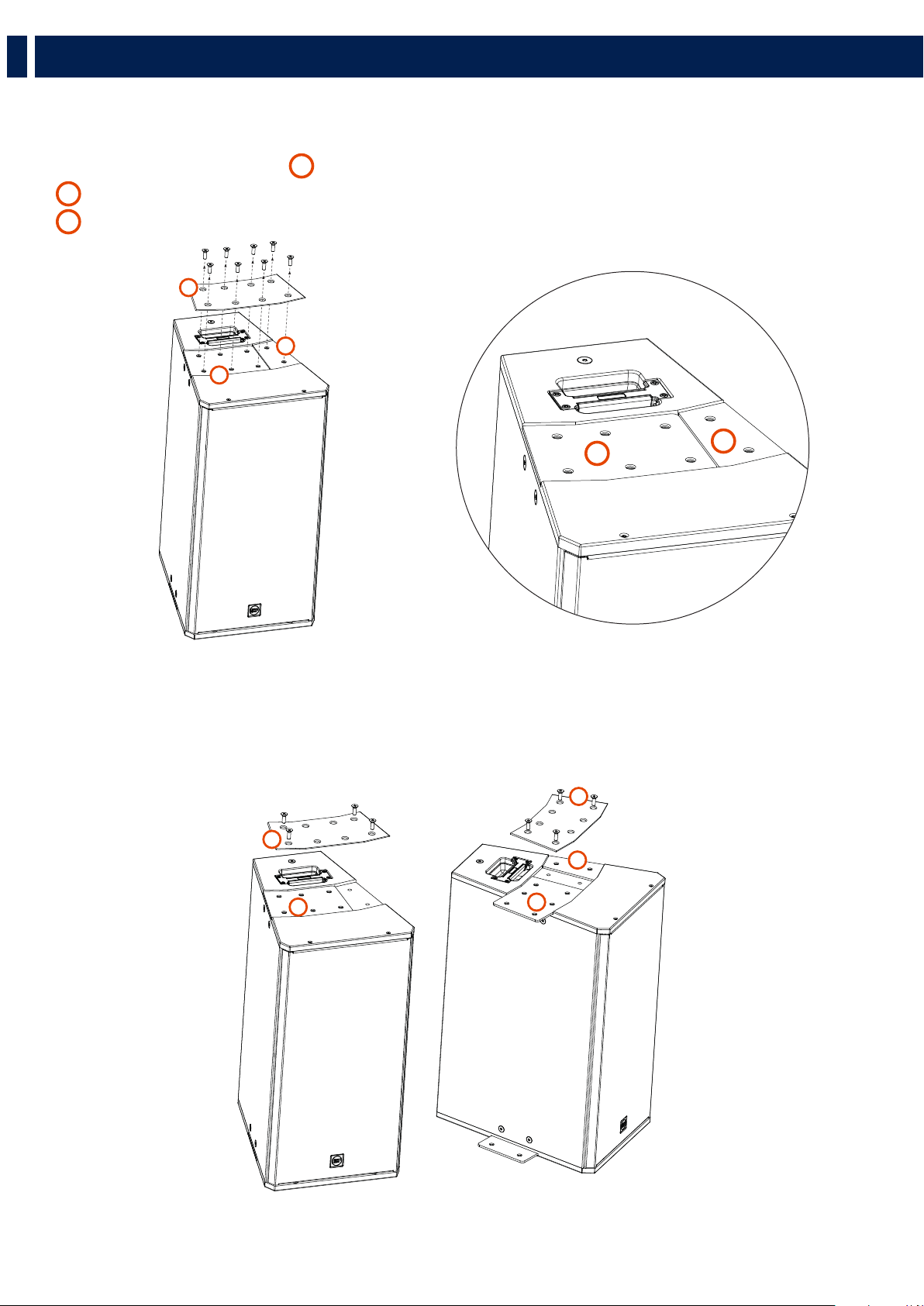
4.1 HORIZONTAL HANGING OF 1 SPEAKER
1. Unscrew the 4 central screws from the Top Plate
2. Secure the Flybar with the 4 x M10 screws provided.
TOP VIEW
1 2
10
EN
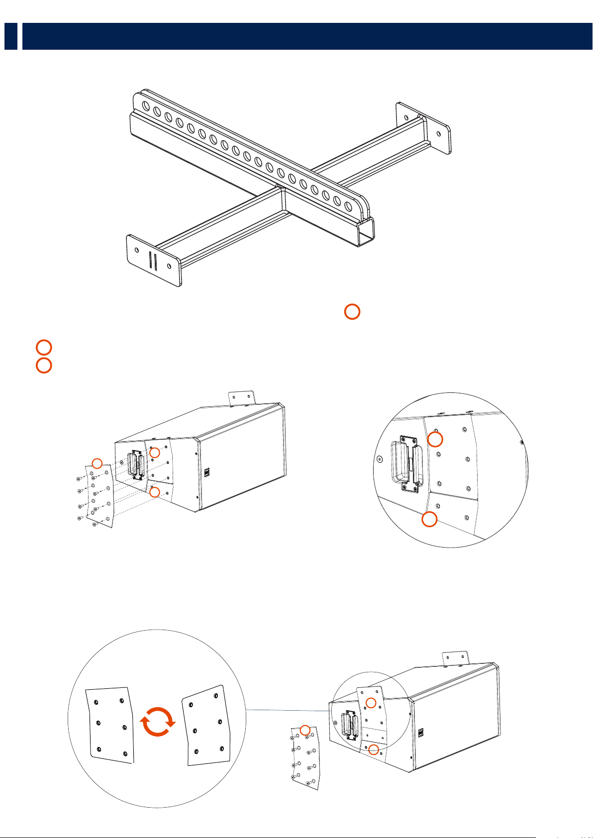
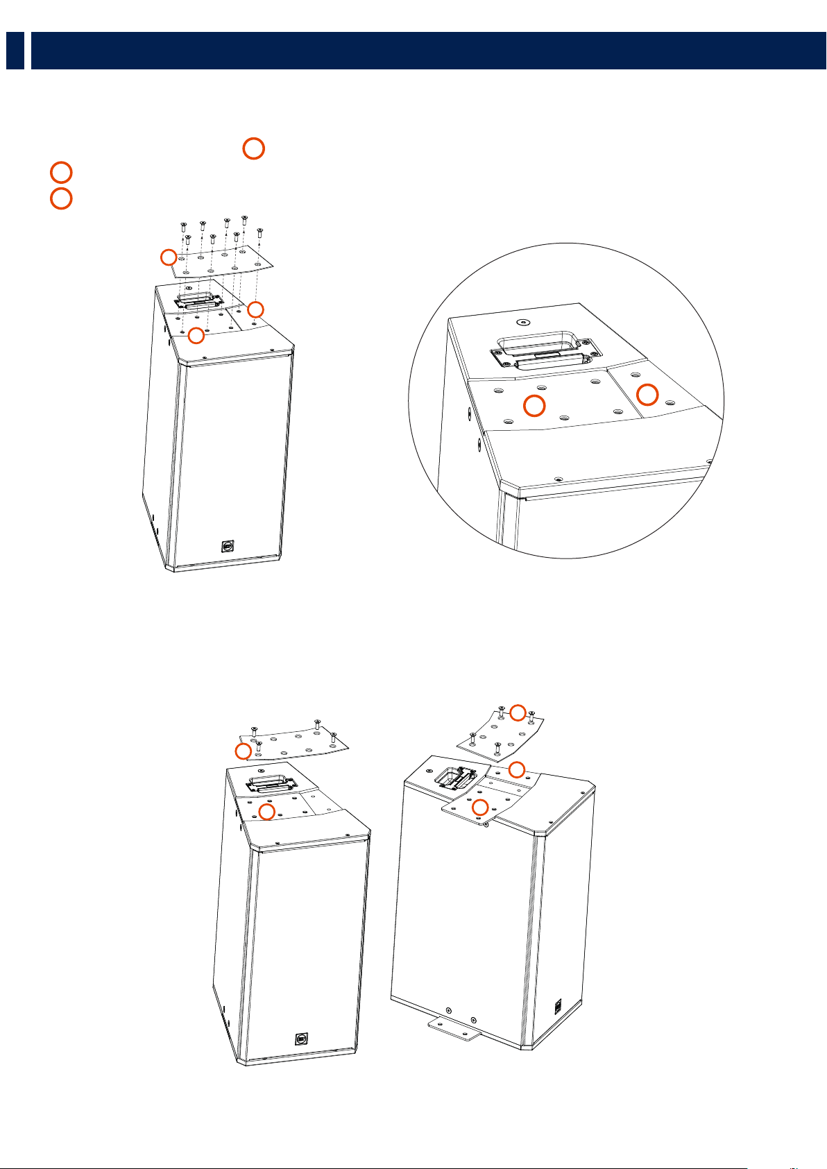
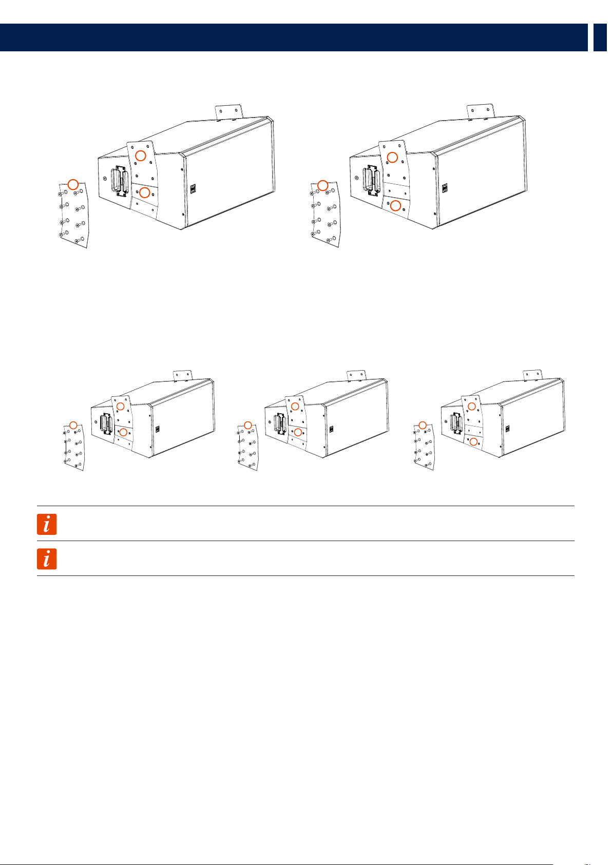
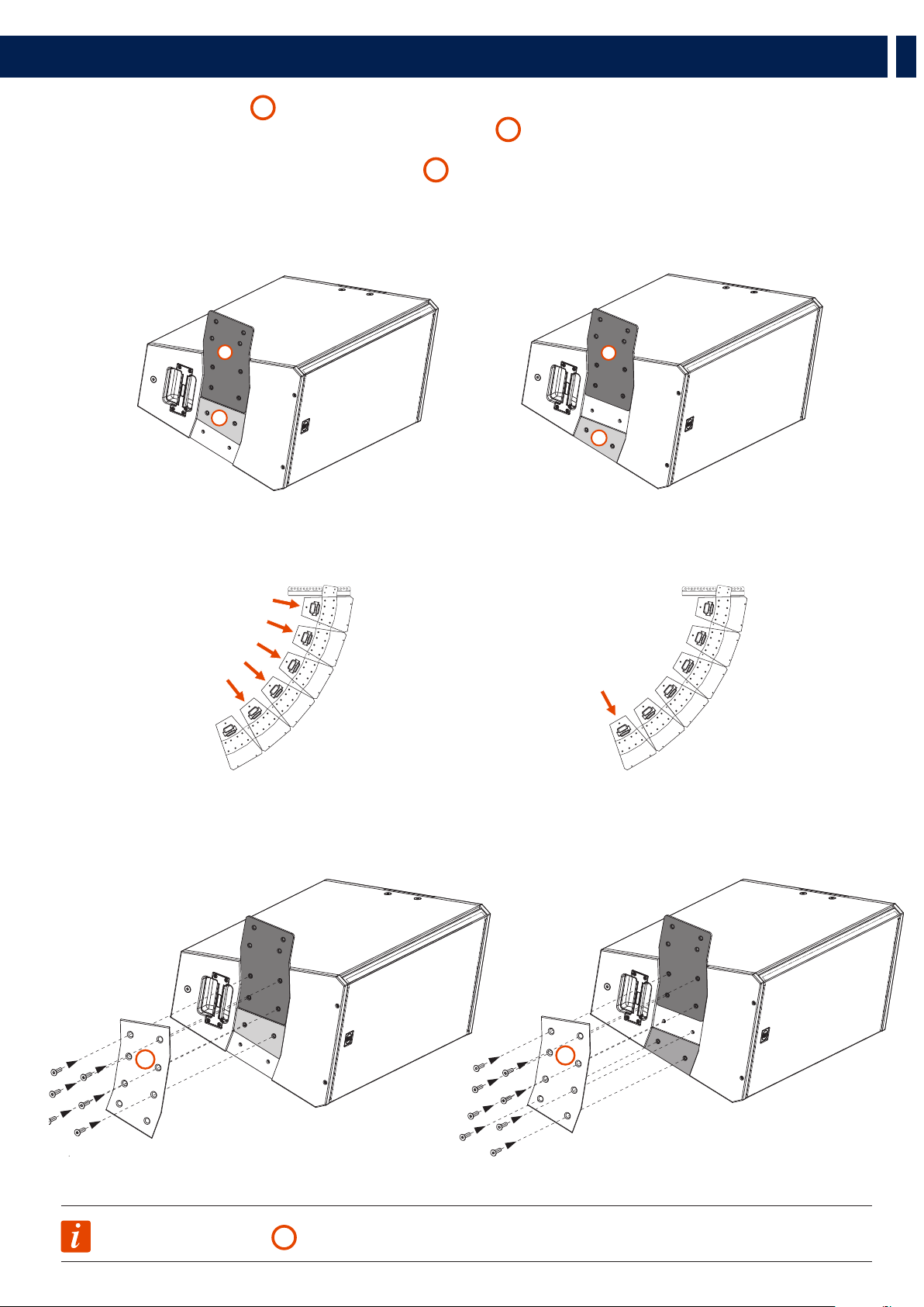
4.2 HORIZONTAL HANGING OF 2 OR MORE SPEAKERS
Unscrew the 8 screws from the Top Plate
A
and remove it. There are 2 plates below the Top Plate:
B
a Link Plate (with 6 holes)
C
an External Plate (with 2 holes)
These two plates are designed to be moved from their position in order to link another speaker on its side depending on the configuration wanted.
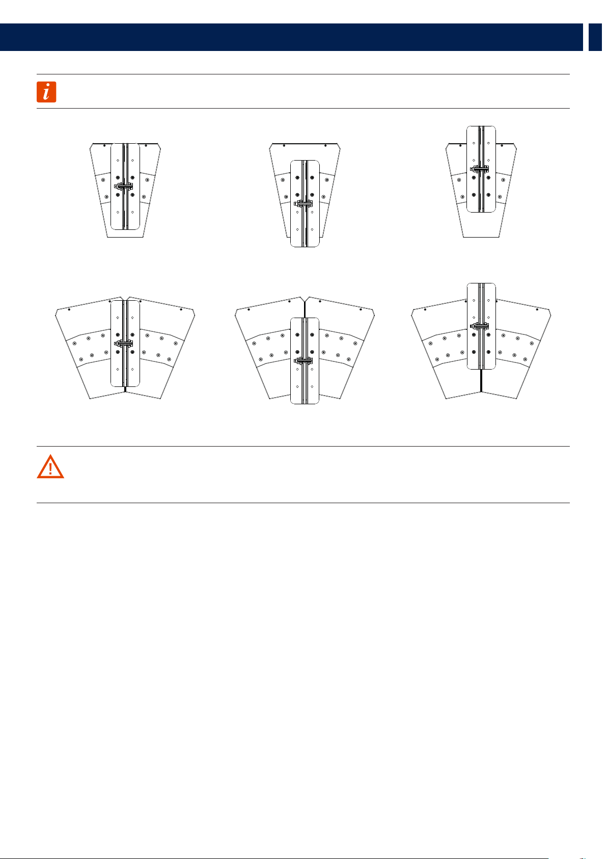
Example: for a 2 speakers horizontal configuration, this is how the two plates must be positioned:
4. HORIZONTAL HANGING
C
A
B
B
C
C
A
A
B
B
11
EN
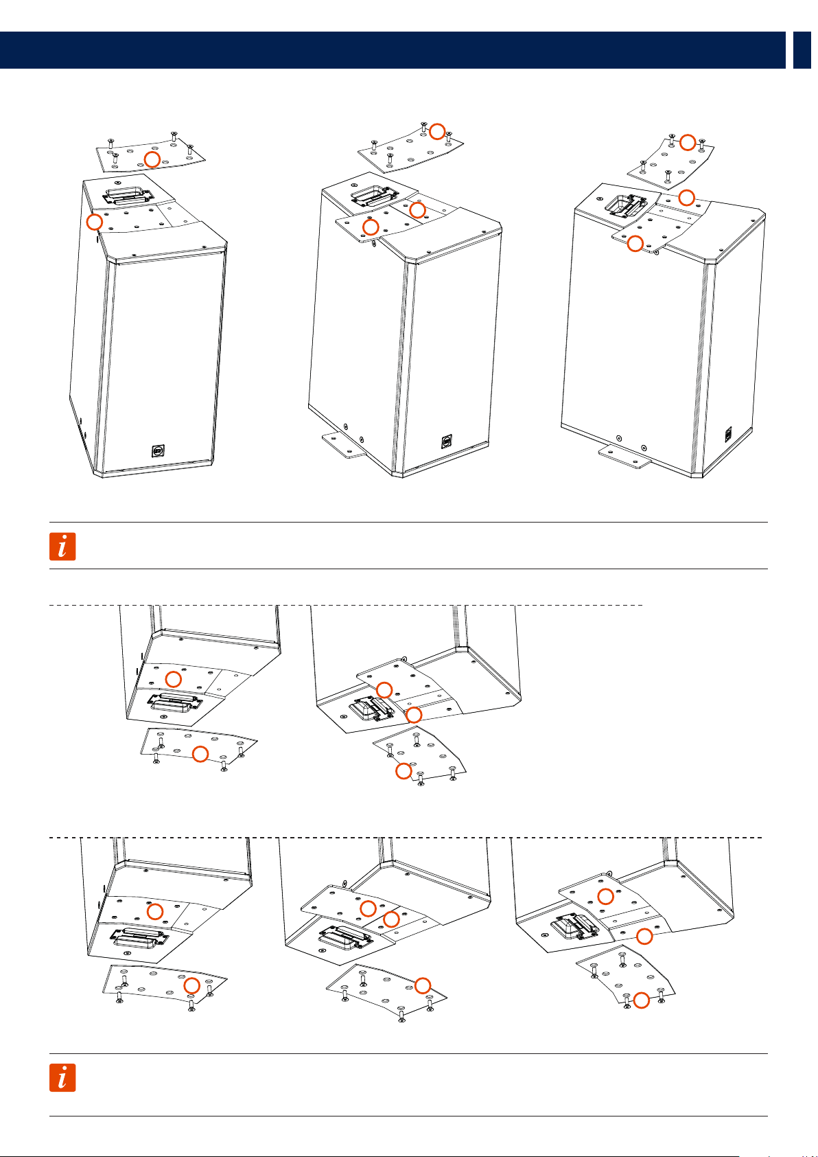
Example: for a 3 speakers configuration, this is how the two plates must be positioned:
NOTE: Once chosen the right configuration the Top Plate must be always screwed back on its position, leaving the four
middle holes free.
4. HORIZONTAL HANGING
NOTE: The exact same operations done on the upper side of the speaker must be done on the bottom side too.
BOTTOM VIEW of a 2 SPEAKERS CONFIGURATION
BOTTOM VIEW of a 3 SPEAKERS CONFIGURATION
C
A
A
B
B
C
A
B
C
A
A
B
B
C
C
A
A
A
B
B
B

12
EN
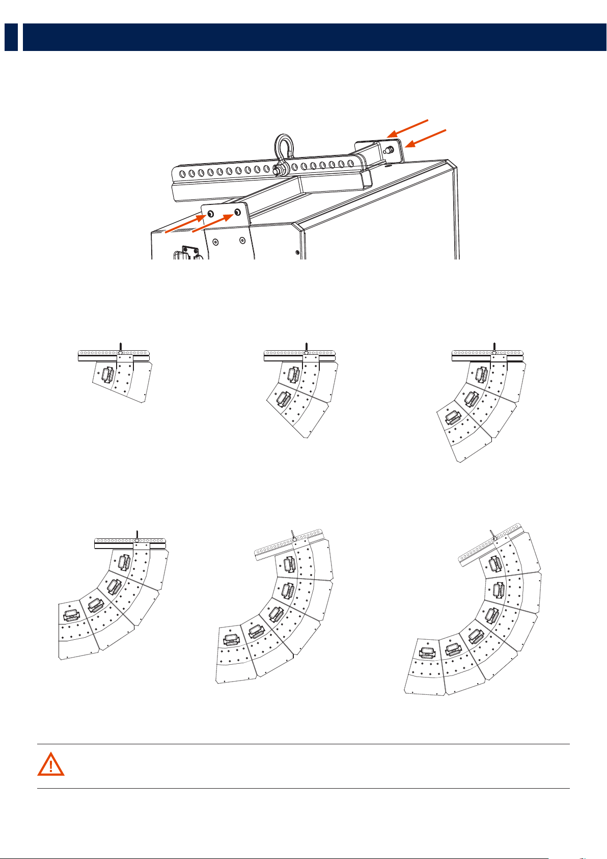
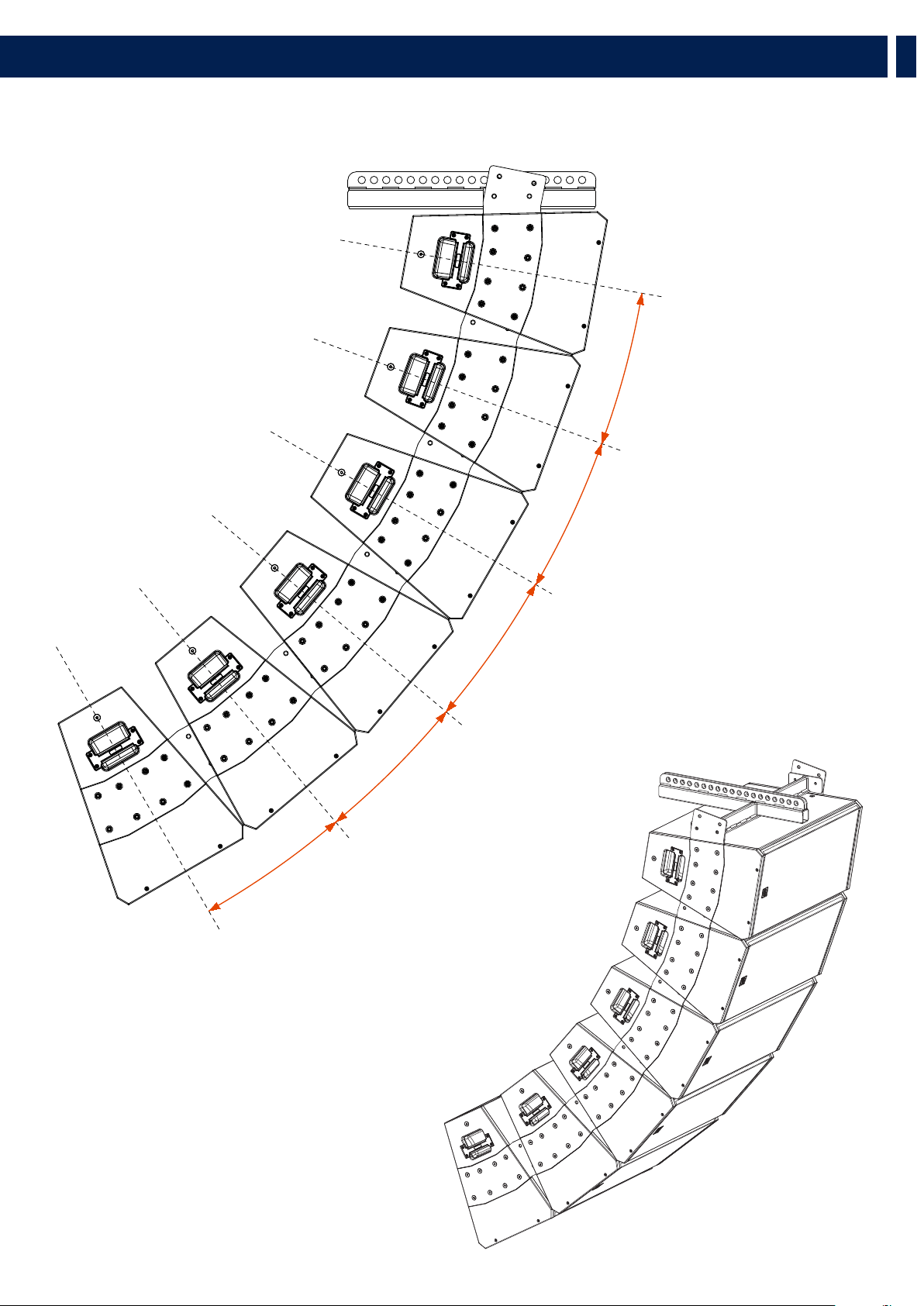
4.3 HORIZONTAL CONFIGURATIONS
Once screwed back the top plate, secure the horizontal flybar over the top plate by screwing (on the middle holes) the four M10 screws provided.
These are all the 4 possible configurations by using one single Flybar:
4. HORIZONTAL HANGING
1 SPEAKER
HORIZONTAL
CONFIGURATION
3 SPEAKERS
HORIZONTAL
CONFIGURATION
2 SPEAKERS
HORIZONTAL
CONFIGURATION
4 SPEAKERS
HORIZONTAL
CONFIGURATION

13
EN
4. HORIZONTAL HANGING
NOTE: The Flybar can be positioned backward or forward to even increase the desired inclination.
CAUTION: do not hang more than 4 speakers to one single horizontal flybar. To hang 5 ore more speakers, more
horizontal flybars are required.
FLYBAR ON
CENTRAL
POSITION
FLYBAR ON
FORWARD
POSITION
FLYBAR ON
BACKWARD
POSITION
14
EN
To vertically hang a series of Q 15 speakers, unscrew the 8 screws from the Top Plate
A
and remove it.
As described on chapter 4.1
(Horizontal hanging of 2 or more speakers)
, two plates are located under the top one:
B
a Link Plate (with 6 holes)
C
an External Plate (with 2 holes)
These two plates are designed to be moved from their position in order to link another speaker on its side depending on the configuration wanted.
Example: for a 1 speaker vertical configuration, this is how the two plates must be positioned:
PLATES B MUST BE ROTATED
UPSIDE DOWN
5. VERTICAL HANGING
4 x Q 15 can be hanged vertically by using the vertical flybar FLY BAR FL-B V Q 15.
B
C
B
A
C
B
A
C

15
EN
5. VERTICAL HANGING
TOP SPEAKER
TOP SPEAKER MIDDLE SPEAKER
LOWER SPEAKER
LOWER SPEAKER
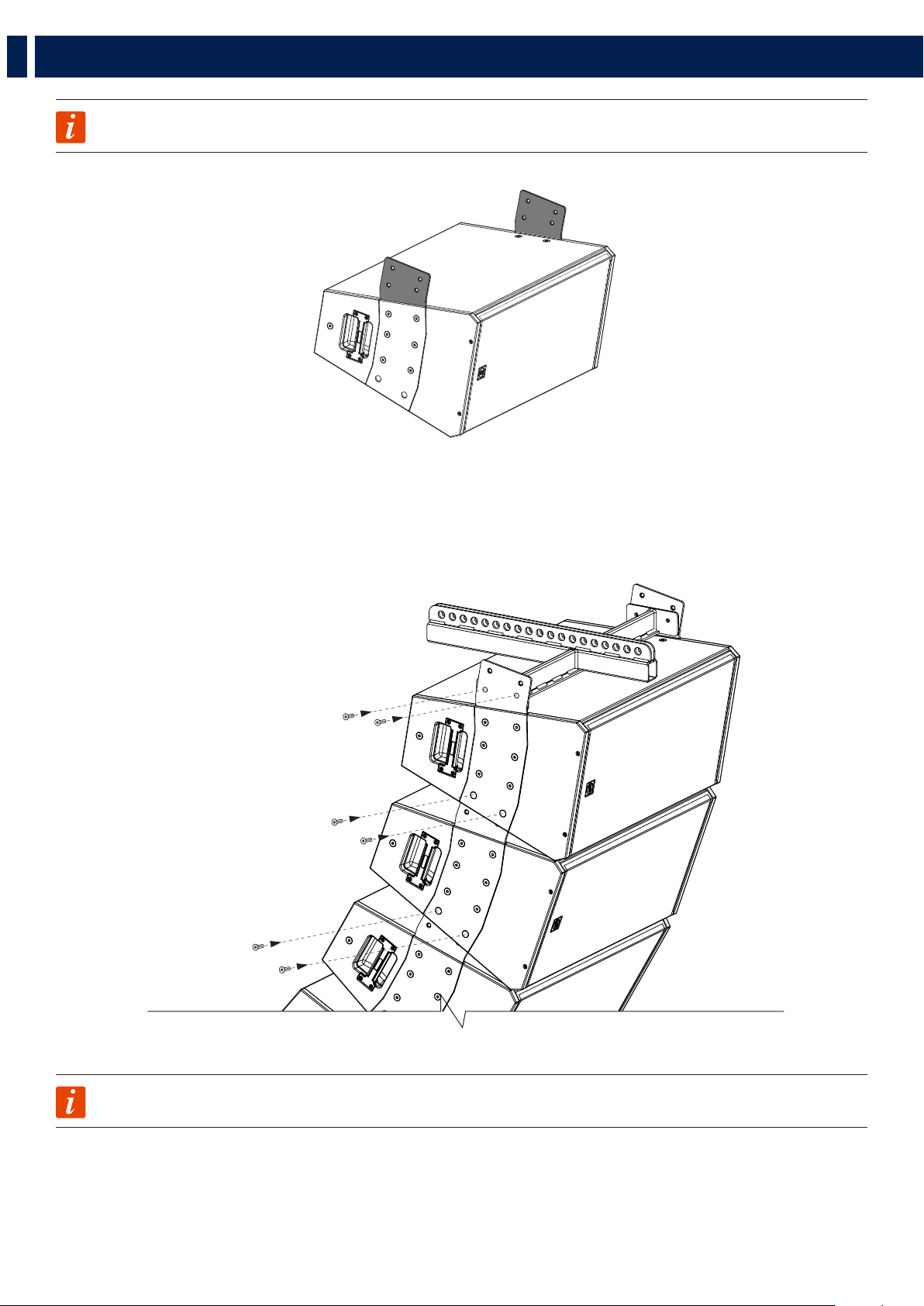
Example: for a 3 speakers vertical configuration, this is how the plates must be positioned:
Example: for a 2 speakers vertical configuration, this is how the plates must be positioned:
NOTE: The exact same operations must be done on both sides of the speaker
NOTE: Once chosen the right configuration the Top Plate must be always screwed back on its position.
B
A
C
B
A
C
B B B
A A A
C C
C

16
EN
5. VERTICAL HANGING
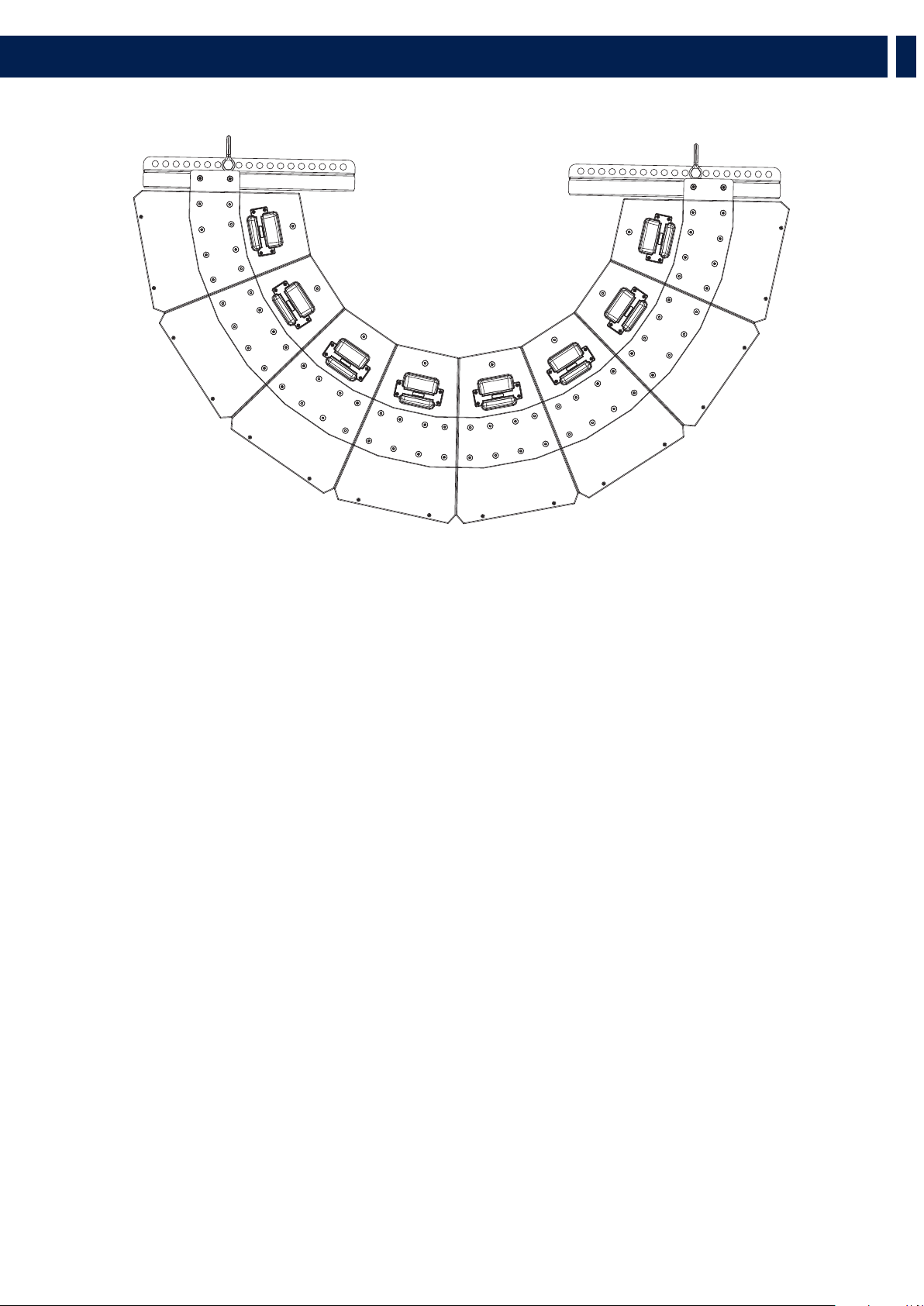
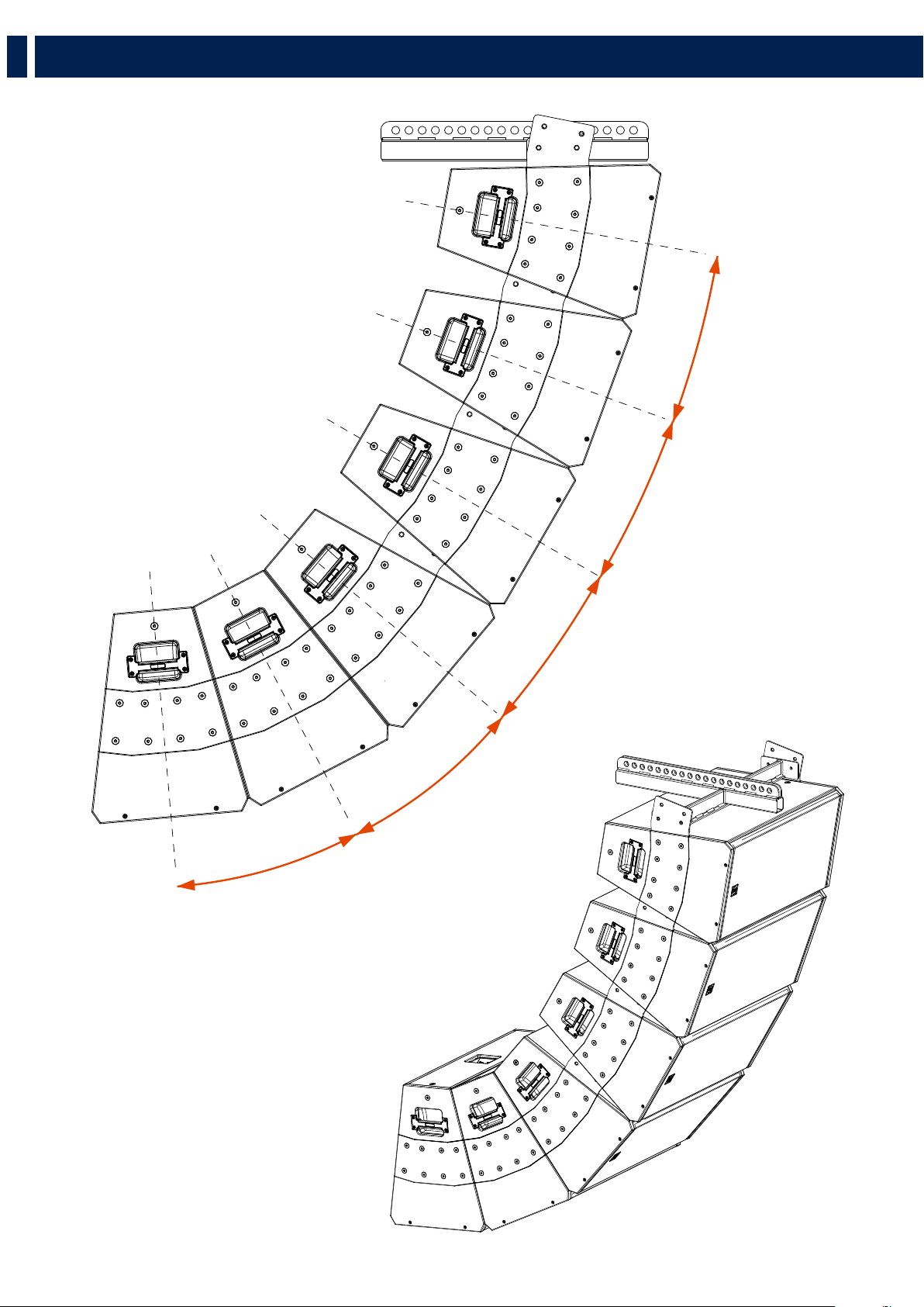
5.1 VERTICAL CONFIGURATIONS
Once screwed back the top plate, secure the vertical flybar on the exposed portion of the Link Plate with the four M10 bolts provided.
Secure every bolt with the eight nuts provided (two nuts for each bolt).
These are the possible horizontal configurations by using one single Flybar:
1 SPEAKER
4 SPEAKERS
3 SPEAKERS
6 SPEAKERS
2 SPEAKERS
5 SPEAKERS
CAUTION: do not hang more than 6 speakers to one single vertical flybar.
17
EN
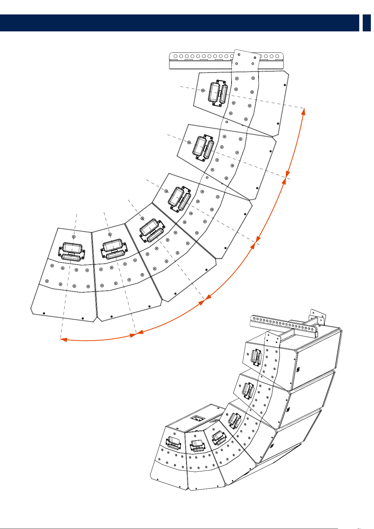
5. VERTICAL HANGING
An additional 8 speakers vertical configuration can be done by using two vertical flybars.

18
EN
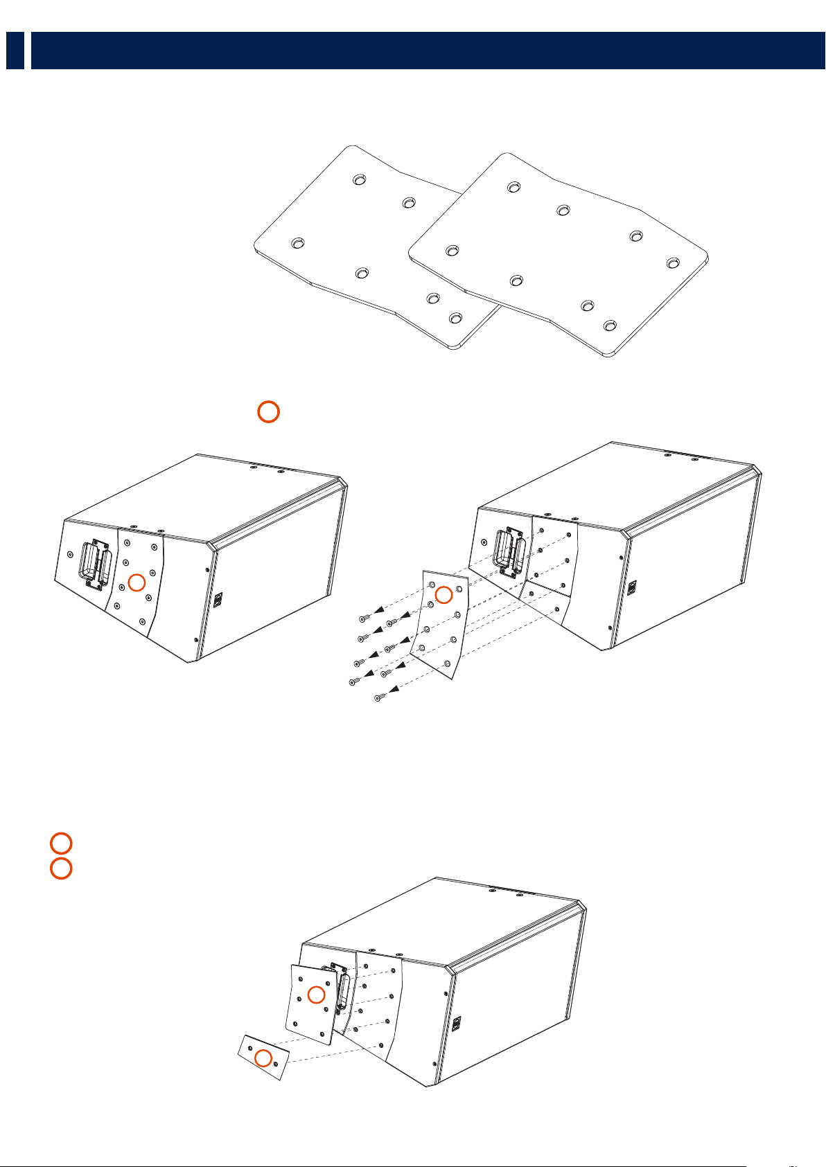
6. VERTICAL HANGING WITH A 10° ANGLE
Using the C-BR 10° it is possible to reduce the opening angle from 22.5° to 10°.
PACKAGE CONTENT:
- 2 X C-BR 10° BRACKETS
1. Unscrew the 8 screws from the Top Plate
A
and remove it.
2. Remove the two plates located under the top one:
B
a Link Plate (with 6 holes)
C
an External Plate (with 2 holes)
A
A
B
C

19
EN
6. VERTICAL HANGING WITH A 10° ANGLE
3. Place the C-BR 10°
D
as shown in the pictures below.
- On the top and following speakers of the cluster, the External Plate
C
must be placed next to the C-BR 10°, as shown in FIGURE 1.
- On the bottom speaker of the cluster the External Plate
C
must be placed as shown in FIGURE 2.
4. For the top and following speakers, place back the Top Plate on its position and screw it back with only six screws, leaving the two bottom holes
empty. For the Bottom speakers screw back the Top Plate with all the 8 screws.
NOTE: The Top Plate
A
must be always screwed back on its position.
FIGURE 1
(Top and following speakers)
(Top and following speakers)
C
D
FIGURE 2
(Bottom speaker)
(Bottom speaker)
C
D
A
A
20
EN
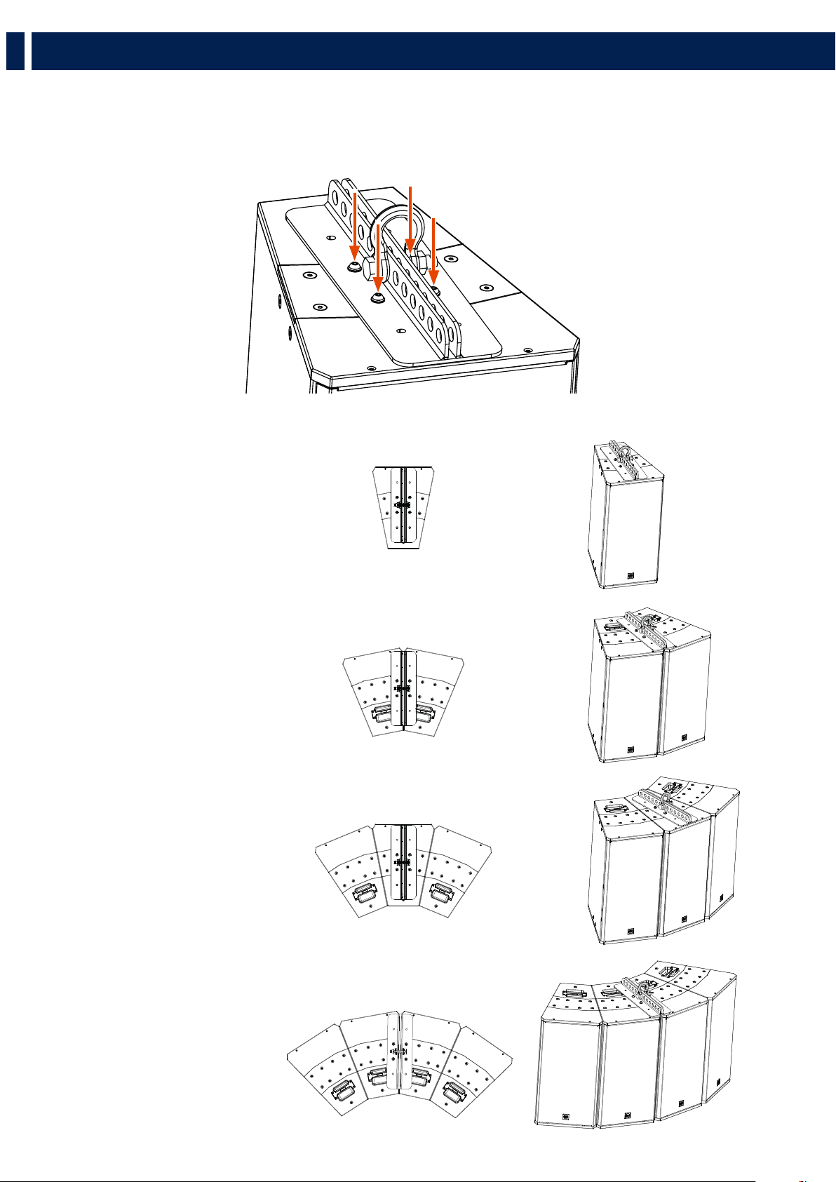
5. Now place the Vertical Fly Bar on top of a Q15 speaker and screw it with the 4 screws provided.
The protruding part of the 10° bracket of the lower speaker must be inserted on the respective seat on the upper speaker. Then depending on
which angle is chosen, screw in the last two screws.
NOTE: The exact same operations must be done on both sides of the speaker
NOTE: The exact same operations must be done on both sides of the speaker
6. VERTICAL HANGING WITH A 10° ANGLE

21
EN
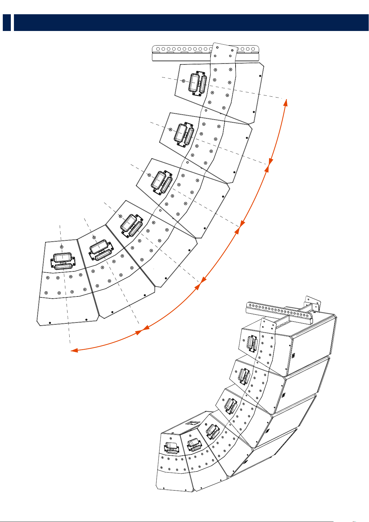
Now with the the vertical flybar FLY BAR FL-B V Q 15 you can hang vertically multiple Q 15 speakers (maximum 6).
10°
10°
10°
10°
10°
EXAMPLE
6 X 10° modules
7. EXAMPLES OF CONFIGURATIONS
22
EN
7. EXAMPLES OF MIXED CONFIGURATIONS
10°
10°
22.5°
10°
22.5°
EXAMPLE
4 X 10° modules + 2 x 22.5° modules
23
EN
7. EXAMPLES OF MIXED CONFIGURATIONS
10°
10°
22.5°
22.5°
22.5°
EXAMPLE
3 X 10° modules + 3 x 22.5° modules
24
IT
I simboli utilizzati in questo documento notificano importanti istruzioni operative e
avvertimenti che devono essere seguiti attentamente.
CAUTELA
Importante istruzione operativa: notifica un
pericolo che potrebbe danneggiare il prodotto,
compresa la perdita di dati
ATTENZIONE
Avvertimento importante riguardante l’uso
di voltaggi pericolosi e il potenziale rischio di
shock elettrico, lesioni personali o morte.
NOTE IMPORTANTI
Informazioni utili e rilevanti sull’argomento
SUPPORTI,
TROLLEY E
CARRRELLI
Informazioni riguardanti l’utilizzo di supporti,
trolley e carrelli. Suggerisce di muovere con
estrema cautela e di non inclinare il carico.
SMALTIMENTO
Questo simbolo indica che il prodotto non
deve essere smaltito con i rifiuti ordinari, così
come indicato nella direttiva WEEE (2012/19/
EU) e nelle normative nazionali in vigore.
NOTE IMPORTANTI
Questo manuale contiene informazioni importanti sull’uso corretto e sicuro del dispositivo.
Prima di collegare e utilizzare questo prodotto, leggere attentamente questo manuale
di istruzioni e tenerlo a portata di mano per riferimenti futuri. Il manuale deve essere
considerato parte integrante di questo prodotto e deve accompagnarlo in caso di cambio
proprietà come riferimento per la corretta installazione e utilizzo nonché per le precauzioni
di sicurezza. RCF S.p.A. non si assume alcuna responsabilità per l’installazione e / o l’uso
errati di questo prodotto.
PRECAUZIONI DI SICUREZZA
1. Tutte le precauzioni, in particolare quelle di sicurezza, devono essere lette con particolare
attenzione, in quanto forniscono informazioni importanti.
2. Alimentazione principale da rete elettrica
a. La tensione di rete è sufficientemente elevata da comportare un rischio di folgorazione;
installare e collegare questo prodotto prima di collegarlo.
b. Prima di accendere, assicurarsi che tutti i collegamenti siano stati eseguiti correttamente
e che la tensione della rete corrisponda alla tensione indicata sulla targhetta dei dati
sull’unità, in caso contrario, contattare il rivenditore RCF.
c. Le parti metalliche dell’unità sono messe a terra attraverso il cavo di alimentazione. Un
apparecchio con costruzione di CLASSE I deve essere collegato a una presa di corrente
con un collegamento di terra di protezione.
d. Proteggere il cavo di alimentazione da danni; assicurarsi che sia posizionato in modo
tale da non poter essere calpestato o schiacciato da oggetti.
e. Per evitare il rischio di scosse elettriche, non aprire mai questo prodotto: non sono
previste parti interne alle quali l’utente debba accedere.
f. Fare attenzione: nel caso di un prodotto provvisto solo di connettori POWERCON e
senza cavo di alimentazione, congiuntamente ai connettori POWERCON tipo NAC3FCA
(alimentazione) e NAC3FCB (alimentazione), devono essere usati i seguenti cavi di
alimentazione conformi alla norma nazionale:
- EU: cavo di tipo H05VV-F 3G 3x2.5 mm2 - Standard IEC 60227-1
- JP: cavo di tipo VCTF 3x2 mm2; 15Amp/120V~ - Standard JIS C3306
- US: cavo di tipo SJT/SJTO 3x14 AWG; 15Amp/125V~ - Standard ANSI/UL 62
3. Assicurarsi che nessun oggetto o liquido penetri in questo prodotto poiché ciò potrebbe
causare un corto circuito. Questo apparecchio non deve essere esposto a gocciolamenti o
spruzzi. Nessun oggetto riempito di liquido, come vasi, deve essere posizionato su questo
apparecchio. Nessuna fiamma libera (come candele accese) deve essere posizionata su
questo apparecchio.
4. Non tentare mai di eseguire operazioni, modifiche o riparazioni non espressamente
descritte nel presente manuale.
Contattare il centro di assistenza autorizzato o personale qualificato qualora si verifichi una
delle seguenti condizioni:
- Il prodotto non funziona (o funziona in modo anomalo).
- Il cavo di alimentazione è stato danneggiato.
- Oggetti o liquidi sono entrati nell’unità.
- Il prodotto ha subìto un forte urto.
5. Se questo prodotto non viene utilizzato per un lungo periodo, scollegare il cavo di
alimentazione.
6. Se questo prodotto inizia a emettere strani odori o fumo, spegnerlo immediatamente e
scollegare il cavo di alimentazione.
7. Non collegare questo prodotto ad apparecchiature o accessori non previsti.
Per l’installazione sospesa, utilizzare solo i punti di ancoraggio dedicati e non tentare di
appendere questo prodotto utilizzando elementi non idonei o non specifici per questo
scopo. Verificare inoltre l’idoneità della superficie di supporto a cui è ancorato il prodotto
(parete, soffitto, struttura, ecc.) a dei componenti utilizzati per il fissaggio (tasselli, viti,
staffe non fornite da RCF ecc.) che devono garantire sicurezza del sistema / installazione
nel tempo, anche considerando, ad esempio, le vibrazioni meccaniche normalmente
generate dai trasduttori.
Per evitare il rischio di caduta dell’apparecchiatura, non impilare più unità di questo
prodotto a meno che questa possibilità non sia specificata nel manuale dell’utente.
8.RCF S.p.A. raccomanda vivamente che questo prodotto sia installato solo
da installatori professionisti qualificati (o aziende specializzate) che possono
garantire la corretta installazione e certificarlo secondo le normative vigenti.
L’intero sistema audio deve essere conforme agli standard e alle normative
vigenti in materia di sistemi elettrici.
9. Supporti, trolley e carrelli.
L’apparecchiatura deve essere utilizzata, ove necessario, solo su supporti,
trolley e carrelli consigliati dal produttore. L’apparecchiatura / supporto /
carrello deve essere spostata con estrema cautela. Arresti improvvisi, eccessiva
spinta e pavimenti irregolari possono causarne il ribaltamento. Non inclinare
mai.
10. Vi sono numerosi fattori meccanici ed elettrici da considerare quando si installa un
sistema audio professionale (oltre a quelli strettamente acustici, come la pressione del
suono, gli angoli di copertura, la risposta in frequenza, ecc.).
11. Perdita dell’udito.
L’esposizione a livelli sonori elevati può causare la perdita permanente dell’udito. Il livello
di pressione acustica che porta alla perdita dell’udito è diverso da persona a persona
e dipende dalla durata dell’esposizione. Per prevenire un’esposizione potenzialmente
pericolosa a livelli elevati di pressione acustica, chiunque sia esposto a questi livelli
dovrebbe usare adeguati dispositivi di protezione. Quando viene utilizzato un trasduttore
in grado di produrre alti livelli sonori, è quindi necessario indossare tappi per le orecchie o
cuffie protettive. Vedere le specifiche tecniche del manuale per conoscere il livello massimo
di pressione sonora.
PRECAUZIONI OPERATIVE
- Posizionare questo prodotto lontano da qualsiasi fonte di calore e garantire sempre
un’adeguata circolazione dell’aria attorno ad esso.
- Non sovraccaricare questo prodotto per molto tempo.
- Non forzare mai gli elementi di controllo (tasti, manopole, ecc.).
- Non utilizzare solventi, alcool, benzene o altre sostanze volatili per pulire le parti
esterne di questo prodotto.
NOTE IMPORTANTI
Per evitare il verificarsi di disturbi sui cavi di segnale in linea, utilizzare solo cavi schermati
ed evitare di avvicinarli a:
- Apparecchiature che producono campi elettromagnetici ad alta intensità
- Cavi di alimentazione
- Linee di altoparlanti
ATTENZIONE! CAUTELA! Per evitare il rischio di incendi o
scosse elettriche, non esporre mai questo prodotto a pioggia o umidità.
ATTENZIONE! Per evitare il rischio di scosse elettriche, non collegare
all’alimentazione di rete mentre la griglia è rimossa.
WARNING! Per ridurre il rischio di scosse elettriche, non smontare
questo prodotto se non si è qualificati. Per l’assistenza rivolgersi a personale
di assistenza qualificato
1. AVVERTENZE PER LA SICUREZZA E INFORMAZIONI GENERALI
25
IT
1. AVVERTENZE PER LA SICUREZZA E INFORMAZIONI GENERALI
SMALTIMENTO CORRETTO DI QUESTO PRODOTTO
Questo prodotto deve essere consegnato a un sito di raccolta
autorizzato per il riciclaggio di apparecchiature elettriche ed
elettroniche (AEE). Una manipolazione impropria di questo tipo di rifiuti
potrebbe avere un possibile impatto negativo sull’ambiente e sulla
salute umana a causa di sostanze potenzialmente pericolose che sono
generalmente associati alle AEE. Allo stesso tempo, la vostra collaborazione
per il corretto smaltimento di questo prodotto contribuirà all’utilizzo efficace
delle risorse naturali. Per ulteriori informazioni su dove sia possibile scaricare
le attrezzature per il riciclaggio, si prega di contattare l’ufficio comunale
locale, l’autorità competente per i rifiuti o il servizio di smaltimento dei rifiuti
domestici .
CURA E MANUTENZIONE
Per garantire un servizio di lunga durata, questo prodotto deve essere utilizzato seguendo
questi consigli:
- Se il prodotto deve essere installato all’aperto, assicurarsi che sia coperto e protetto
da pioggia e umidità.
- Se il prodotto deve essere utilizzato in un ambiente freddo, riscaldare lentamente le
bobine vocali inviando un segnale di basso livello per circa 15 minuti prima di inviare
segnali ad alta potenza.
- Utilizzare sempre un panno asciutto per pulire le superfici esterne dell’altoparlante e
farlo sempre quando l’alimentazione è spenta
CAUTELA! Per evitare di danneggiare le finiture esterne non
utilizzare solventi per la pulizia o abrasivi.
ATTENZIONE! CAUTELA! Per gli altoparlanti alimentati,
eseguire la pulizia solo quando l’alimentazione è spenta.

26
IT
2. DESCRIZIONE
Q 15, Q 15-L, Q 15-P - MODULI POINT SOURCE A DUE VIE
I diffusori Q 15 sono moduli point source a due vie bi-amplificati per applicazioni a media distanza e lunga gittata, che uniscono dimensioni
compatte con una potenza di uscita molto elevata ed una riproduzione accurata di voce e suono. I sistemi sono dotati di trasduttori RCF di ultima
generazione: un woofer al neodimio da 15” (4.0” di bobina) ed un driver a compressione con uscita da 1.4” (4.0” di bobina) che forniscono una
potenza nominale di 1500 W.
La direttività, orizzontale di 22.5° e verticale di 60° (Q 15), 90° (Q 15-L), 40° (Q 15-P) rende i diffusori Q 15 ideali per essere utilizzati come
sorgenti puntiformi per applicazioni a media distanza o uniti ad array con angoli più stretti per applicazioni a lunga gittata. La forma trapezoidale
del mobile offre un angolo di accoppiamento di 22,5° su ciascun lato. Grazie a due diversi modelli di fly bar, possono essere raggruppati sia
in orizzontale (fino a 4 moduli con lo stesso fly bar) che in verticale (fino a 6 moduli con singolo flybar e fino a 8 moduli con doppio fly-bar). I
collegamenti con l’amplificatore vengono effettuati tramite connettori multipolari Speakon. La griglia è in acciaio rivestita con vernice epossidica,
abbinata con tessuto intrecciato. Il cabinet è realizzato in multistrato di betulla del Baltico e rifinito con vernice poliuretanica nera molto resistente.
Q 15
Direttività orizzontale: 22.5°
Direttività verticale: 60°
Q 15-L
Direttività orizzontale: 22.5°
Direttività verticale: 90°
Q 15-P
Direttività orizzontale: 22.5°
Direttività verticale: 40°
27
IT
IL PANNELLO POSTERIORE
Sul pannello posteriore sono presenti 2 prese, entrambe per connettori ‘Neutrik Speakon NL4’ (4 poli):
1
La presa INPUT riceve il segnale dall’amplificatore
2
La presa LINK può essere usata per collegare un altro diffusore
MODO “BI-AMP” (bi-amplificazione)
Occorrono due amplificatori (uno per le basse frequenze ed uno per le alte) ed un crossover esterno. Verificare nella tabella dei dati tecnici
l’impedenza di ciascuna sezione, le potenze applicabili e la frequenza suggerita di crossover..
LOW
HIGH
AMP.
CROSSOVER
AMP.
COLLEGAMENTI
- uscita + basse frequenze dell’amplificatore al contatto 1+ del connettore SPEAKON;
- uscita – basse frequenze dell’amplificatore al contatto 1– del connettore SPEAKON;
- uscita + alte frequenze dell’amplificatore al contatto 2+ del connettore SPEAKON;
- uscita – alte frequenze dell’amplificatore al contatto 2– del connettore SPEAKON.
ATTENZIONE! CAUTELA! Per il collegamento del diffusore si raccomanda di rivolgersi a personale qualificato
ed addestrato, ossia personale avente conoscenze tecniche o esperienza o istruzioni specifiche sufficienti per permettergli di
realizzare correttamente le connessioni e prevenire i pericoli dell’elettricità.
Per evitare il rischio di shock elettrici, non collegare il diffusore con l’amplificatore acceso.
Prima di far funzionare il diffusore, è buona norma ricontrollare tutte le connessioni, verificando attentamente che non vi
siano dei cortocircuiti accidentali. Tutto l’impianto di sonorizzazione dovrà essere realizzato in conformità con le norme e le
leggi vigenti in materia di impianti elettrici.
3. COLLEGAMENTI
21
28
IT
NOTE SUI SISTEMI CON CONNESSIONE A BASSA IMPEDENZA
-+
+
+
-+
+
ATTENZIONE! CAUTELA!
- L’impedenza totale dei diffusori non deve essere inferiore a quella d’uscita dell’amplificatore; nota: l’impedenza complessiva
dei diffusori uguale a quella d’uscita dell’amplificatore permette l’erogazione della massima potenza (mentre un’impedenza
superiore comporta una riduzione della potenza erogata).
- La somma delle potenze dei diffusori deve essere adeguata alla potenza massima erogabile dall’amplificatore.
- La lunghezza delle linee diffusori deve essere ridotta al minimo (una lunga distanza può comportare l’uso di cavi con sezioni
elevate).
- Utilizzare dei cavi con conduttori aventi una sezione adeguata, considerando la loro lunghezza e la potenza complessiva dei
diffusori.
- Per evitare che fenomeni induttivi diano luogo a ronzii, disturbi e compromettano il funzionamento del sistema, i cavi per i
diffusori non devono essere canalizzati assieme ai conduttori dell’energia elettrica, ai cavi microfonici od altre linee.
- Per minimizzare gli effetti induttivi (ronzii) dovuti all’accoppiamento con campi elettromagnetici circostanti, utilizzare cavi
con conduttori intrecciati.
- NON collegare gli ingressi dei diffusori direttamente ad una linea a tensione costante (es. 100 V).
3. COLLEGAMENTI
29
IT
4. SOSPENSIONE ORIZZONTALE
Utilizzando il flybar FLY BAR FL-B H Q 15 possono essere sospesi orizzontalmente fino a 4 diffusori Q 15.
4.1 SOSPENSIONE ORIZZONTALE DI 1 DIFFUSORE
1. Svitare le 4 viti centrali dalla piastra superiore
2. Avvitare il flybar con le 4 viti M10 in dotazione.
TOP VIEW
1 2
30
EN
4.2 SOSPENSIONE ORIZZONTALE DI 2 O PIÙ DIFFUSORI
Svitare le 8 viti dalla piastra superiore
A
e rimuoverla. Sotto alla piastra superiore ci sono altre 2 piastre:
B
una piastra di collegamento (con 6 fori)
C
una piastra esterna (con 2 fori)
Queste due piastre sono progettate per essere spostate dalla loro posizione in modo da poter collegare un altro diffusore a fianco a seconda della
configurazione desiderata.
Esempio: per una configurazione orizzontale a 2 diffusori, le due piastre devono essere posizionate in questo modo:
4. SOSPENSIONE ORIZZONTALE
C
A
B
B
C
C
A
A
B
B

31
EN
Esempio: per una configurazione orizzontale a 3 diffusori, le due piastre devono essere posizionate in questo modo:
NOTE: Una volta scelta la configurazione corretta, la piastra superiore deve essere sempre avvitata nella sua posizione,
lasciando liberi i quattro fori centrali.
4. SOSPENSIONE ORIZZONTALE
NOTA: Le stesse operazioni eseguite sul lato superiore del diffusore devono essere eseguite anche sul lato inferiore.
VISTA INFERIORE di una CONFIGURAZIONE A 2 DIFFUSORI
VISTA INFERIORE di una CONFIGURAZIONE A 3 DIFFUSORI
C
A
A
B
B
C
A
B
C
A
A
B
B
C
C
A
A
A
B
B
B
32
EN
4.3 CONFIGURAZIONI ORIZZONTALI
Una volta avvitata la piastra superiore, fissare il flybar sulla piastra superiore avvitando sui fori centrali le quattro viti M10 fornite.
Queste sono le 4 possibili configurazioni utilizzando un solo Flybar:
4. SOSPENSIONE ORIZZONTALE
CONFIGURAZIONE
ORIZZONTALE A 1
DIFFUSORE
CONFIGURAZIONE
ORIZZONTALE A 3
DIFFUSORI
CONFIGURAZIONE
ORIZZONTALE A 2
DIFFUSORI
CONFIGURAZIONE
ORIZZONTALE A 4
DIFFUSORI
33
EN
4. SOSPENSIONE ORIZZONTALE
NOTA: Il Flybar può essere posizionato all’indietro o in avanti per aumentare ulteriormente l’inclinazione desiderata.
CAUTELA: non sospendere più di 4 diffusori con un singolo flybar orizzontale. Per sospendere 5 o più diffusori serviranno
più flybar orizzontali.
FLYBAR IN
POSIZIONE
CENTRALE
FLYBAR IN
POSIZIONE
POSTERIORE
FLYBAR IN
POSIZIONE
ANTERIORE

34
EN
Per sospendere verticalmente una serie di diffusori Q 15, svitare le 8 viti dalla piastra superiore
A
e rimuoverla.
Così come descritto nel capitolo 4.1
(Sospensione orizzontale di 2 o più diffusori)
, sotto alla piastra superiore ci sono altre due piastre:
B
una piastra di collegamento (con 6 fori)
C
una piastra esterna (con 2 fori)
Queste due piastre sono progettate per essere spostate dalla loro posizione in modo da poter collegare un altro diffusore a fianco a seconda della
configurazione desiderata.
Esempio: per una configurazione orizzontale a 1 diffusore, le due piastre devono essere posizionate in questo modo:
5. SOSPENSIONE VERTICALE
Utilizzando il flybar FLY BAR FL-B V Q 15 possono essere sospesi verticalmente fino a 4 diffusori Q 15.
B
C
B
A
C
LE PIASTRE B DEVONO
ESSERE CAPOVOLTE
B
A
C
35
EN
5. SOSPENSIONE VERTICALE
DIFFUSORE
SUPERIORE
DIFFUSORE
INFERIORE
DIFFUSORE
SUPERIORE
DIFFUSORE
INTERMEDIO
DIFFUSORE
INFERIORE
Esempio: per una configurazione verticale a 3 diffusori, le due piastre devono essere posizionate in questo modo:
Esempio: per una configurazione verticale a 2 diffusori, le due piastre devono essere posizionate in questo modo:
NOTA: Le stesse operazioni devono essere eseguite su entrambi i lati del diffusore.
NOTA: Una volta scelta la configurazione corretta, la piastra superiore deve essere sempre riavvitata nella sua posizione.
B
A
C
B
A
C
B B B
A A A
C C
C
36
EN
5. SOSPENSIONE VERTICALE
4.1 CONFIGURAZIONI VERTICALI
Una volta avvitata la piastra superiore, fissare il flybar verticale sulla parte esposta della piastra di collegamento con i quattro bulloni M10 forniti.
Fissare ogni bullone con gli otto dadi forniti (due dadi per ciascun bullone)
Queste sono le 4 possibili configurazioni utilizzando un solo Flybar:
CAUTELA: non sospendere più di 6 diffusori con un singolo flybar verticale.
1 DIFFUSORE
4 DIFFUSORI
3 DIFFUSORI
6 DIFFUSORI
2 DIFFUSORI
5 DIFFUSORI

37
EN
5. SOSPENSIONE VERTICALE
Un’ulteriore configurazione a 8 diffusori può essere fatta mediante l’utilizzo di 2 flybar.
38
EN
6. SOSPENSIONE VERTICALE CON ANGOLO DI 10°
Mediante l’utilizzo della staffa C-BR 10° è possibile ridurre l’angolo di apertura da 22.5° a 10°.
CONTENUTO DELLA CONFEZIONE:
- 2 X STAFFE C-BR 10°
1. Svitare le 8 viti dalla Piastra Superiore
A
e rimuoverla.
2. Rimuovere le due piastre sottostanti la Piastra Superiore:
B
la Piastra di Collegamento (con 6 fori)
C
la Piastra Esterna (con 2 fori)
A
A
B
C
39
EN
6. SOSPENSIONE VERTICALE CON ANGOLO DI 10°
3. Posizionare la staffa C-BR 10°
D
come mostrato nelle immagini sotto.
- Sul primo diffusore in alto e sui seguenti del cluster, la Piastra Esterna
C
deve essere posizionata di fianco alla staffa C-BR 10°, come
mostrato nella FIGURA 1.
- Nell’ultimo diffusore in basso del cluster, la Piastra Esterna
C
deve essere posizionata come mostrato nella FIGURA 2.
4. Per il primo diffusore in alto e per i seguenti, posizionare la Piastra Superiore nella sua posizione e avvitarla con solo 6 viti, lasciando vuoti i due
fori in basso. Nell’ultimo diffusore in basso avvitare tutte le 8 viti.
NOTA: La Piastra Superiore
A
mdeve sempre essere riavvitata nella sua poszizione.
FIGURA 1
(Primo diffusore in alto e seguenti)
(Primo diffusore in alto e seguenti)
C
D
FIGURA 2
(Ultimo diffusore in basso)
(Ultimo diffusore in basso)
C
D
A
A

40
EN
6. SOSPENSIONE VERTICALE CON ANGOLO DI 10°
5. Posizionare il FlyBar verticale sopra al diffusore Q15 e avvitarlo con le 4 viti in dotazione al FlyBar.
Le staffe sporgenti dell’accessorio 10° devono essere inserite nella loro sede ricavata sotto alla Piastra Superiore del diffusore sovrastante.
Quindi a seconda dell’angolo scelto per l’inclinazione, avvitare le ultime due viti.
NOTA: La medesima operazione deve essere fatta su entrambi i lati del diffusore
NOTA: La medesima operazione deve essere fatta su entrambi i lati del diffusore
41
EN
6. SOSPENSIONE VERTICALE CON ANGOLO DI 10°
Mediante l’utilizzo del flybar verticale FLY BAR FL-B V Q 15 è possibile sospendere un cluster di diffusori Q 15 (massimo 6).
10°
10°
10°
10°
10°
ESEMPIO
6 moduli a 10°
42
EN
7. ESEMPI DI CONFIGURAZIONI MISTE
10°
10°
22.5°
10°
22.5°
ESEMPIO
4 moduli a 10° + 2 moduli a 22.5°
43
EN
7. ESEMPI DI CONFIGURAZIONI MISTE
10°
10°
22.5°
22.5°
22.5°
ESEMPIO
3 moduli a 10° + 3 moduli a 22.5°
44
EN
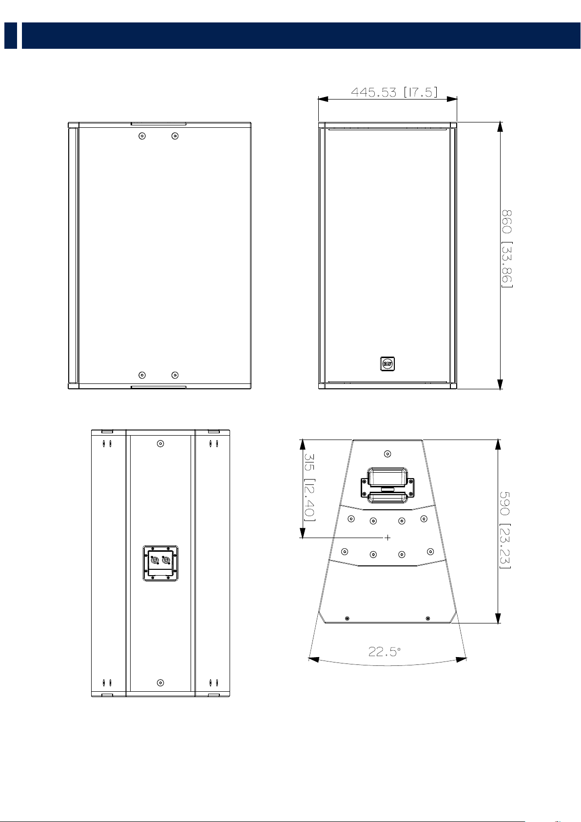
DIMENSIONS
RCF products are continually improved. All specifications are therefore subject to change without notice.
We recommend you to regularly chech the RCF website for the latest version of this document

45
EN
Acoustical specifications
Frequency Response (-10dB):
45 Hz ÷ 20000 Hz
Max SPL @ 1m:
138 dB
Horizontal coverage angle:
22,5°
Vertical coverage angle:
60° (Q 15), 90° (Q 15-L), 40° (Q 15-P)
Directivity index Q:
20
Power section
Nominal Impedance (ohm):
8 ohm
Power Handling:
1500 W RMS
Peak Power Handling:
6000 W PEAK
Recommended Amplifier:
3000 W
Protections:
Capacitor on Compression Driver
Crossover Frequencies:
600 Hz
Transducers
Compression Driver:
1 x 1.4'' neo, 4.0'' v.c
Nominal Impedance (ohm):
8 ohm
Input Power Rating:
150 W AES, 300 W PROGRAM POWER
Sensitivity:
113 dB, 1W @ 1m
Woofer:
15'' neo, 4.0'' v.c
Nominal Impedance (ohm):
8 ohm
Input Power Rating:
1350 W AES, 2700 W PROGRAM POWER
Sensitivity:
97 dB, 1W @ 1m
Input/Output section
Input connectors:
Speakon® NL4
Output connectors:
Speakon® NL4
Standard compliance
CE marking:
Yes
Physical specifications
Cabinet/Case Material:
Baltic birch plywood
Hardware:
Side and rear array rigging point
Handles:
2
Grille:
Steel
Size
Height:
446 mm / 17.56 inches
Width:
860 mm / 33.86 inches
Depth:
590 mm / 23.23 inches
SPECIFICATIONS


Tel +39 0522 274 411 - Fax +39 0522 232 428 - e-mail: info@rcf.it - www.rcf.it
RCF S.p.A. Via Raffaello Sanzio, 13 - 42124 Reggio Emilia - Italy
10307725 RevD