1
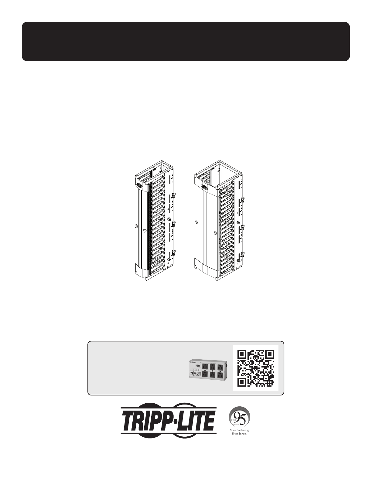
Owner’s Manual
SmartRack
®
Premium
Vertical Cable Managers
6" Models: SRCABLEVRT6HD, SRCABLEVRT6HDFC, SRCABLEVRT6HD2
12” Models: SRCABLEVRT12HD, SRCABLEVRT12HD2
1111 W. 35th Street, Chicago, IL 60609 USA • tripplite.com/support
Copyright © 2021 Tripp Lite. All rights reserved.
Español 10 • Français 19 • Русский 28
WARRANTY REGISTRATION
Register your product today and be
automatically entered to win an ISOBAR
®
surge protector in our monthly drawing!
tripplite.com/warranty
2
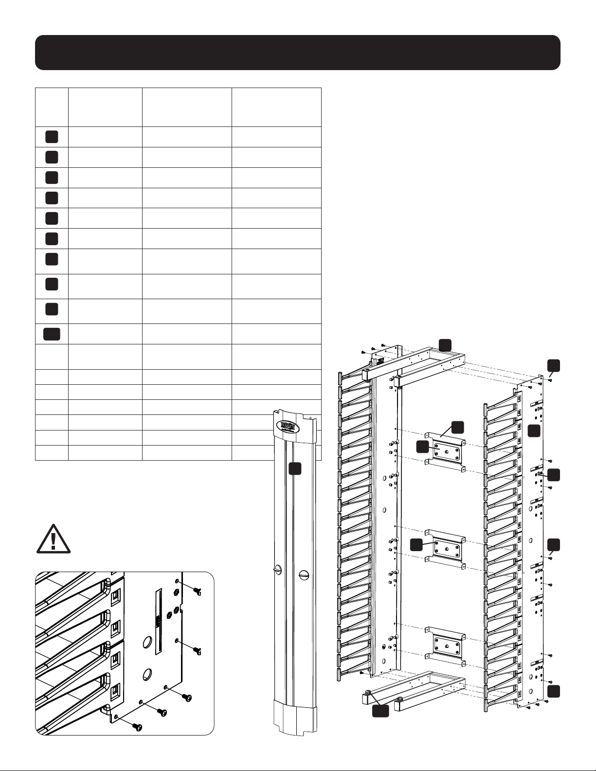
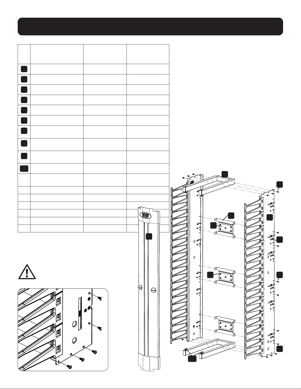
Assembly
Item
No. Description
Qty:
SRCABLEVRT6HD,
SRCABLEVRT6HDFC
Qty:
SRCABLEVRT6HD2,
SRCABLEVRT6HD2F
1
Door Assembly 2 4
2
Weldment 4 8
3
Tie Plate 6 12
4
Cross Bracket 6 12
5
Left Side Panel 2 4
6
Right Side Panel 2 4
7
M4 x 6 mm
Flat Head Screw
6 12
8
M4 x 8 mm
Tap Screw
50 100
9
M4 x 8 mm
Pan Head Screw
24 48
10
Door Bushing 8 16
11* M4 x 12 mm
Pan Head Screw
18 36
12* Mounting Button 6 12
13* Mounting Bracket 6 8
14** 1/2" Hex Bolt 4 8
15** 1/2" Hex Nut 4 8
16** Metal Spacer 4 8
17** 1/2" Washer 4 8
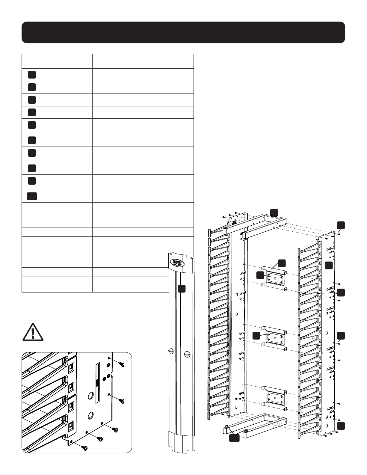
6
3
2
8
10
9 8
When assembling, note the
orientation of the side panels.
The labels “lower”
should be
orientated
on the bottom.
7
8
4
1
*Not shown: Refer to Single-Depth Installation for details.
**Not shown: Refer to Alternate Rack Mounting for details.

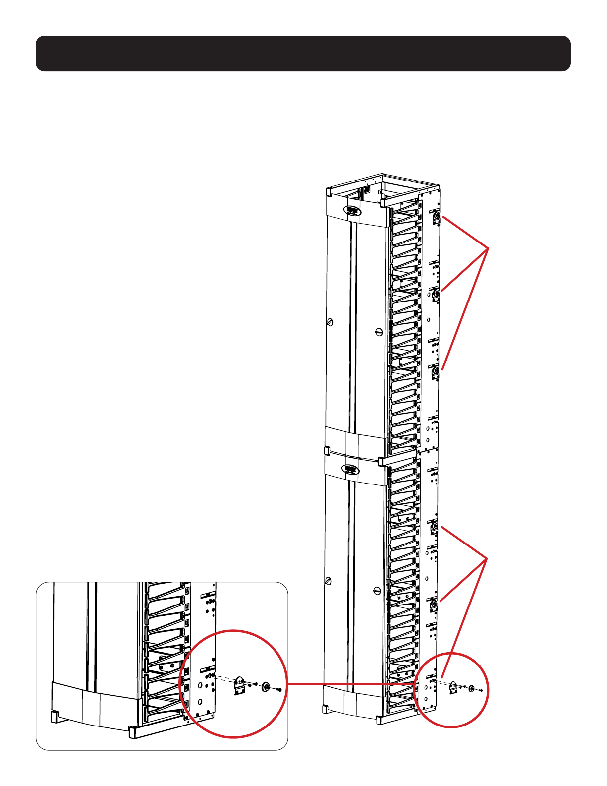
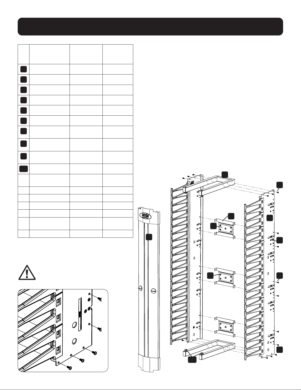
3
When assembling, note the orientation of the Cross Brackets.
If the units are going to be stacked vertically, the upper cable duct should have the Cross Brackets
and PDU Buttons mounted in the upper positions, matching the labels on the side brackets.
Assembly
Configured for
lower mounting
Configured for
upper mounting

4
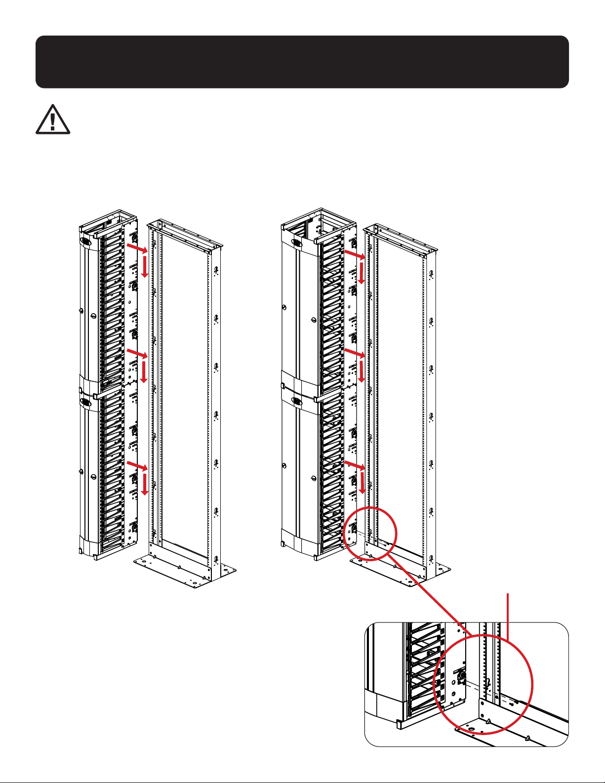
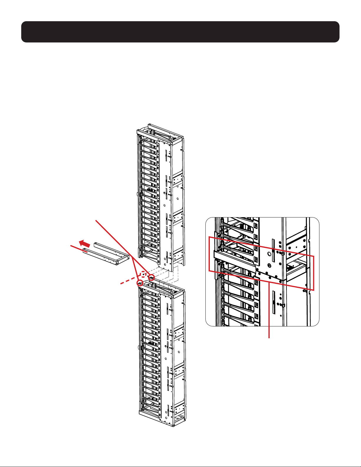
Stacking Vertical Cable Ducts
Upper and lower cable ducts
will share a Weldment when
joined vertically.
Notes
• When assembling for use in stacked vertical configurations, one of the frame Weldments is not used.
• The side panels join to the Weldment of the other cable duct.
• Remove the Door Bushings from the unused Weldment and place them in the Weldment of the other
cable duct to allow for door installation.
Place
Door Bushings
here
One of the
Weldments will
not be used
when joining
the side panels
vertically.
Using (6) M4 x 8 mm
Tap Screws, attach
the Side Panels of
the top cable duct to
the Weldment of the
bottom duct.

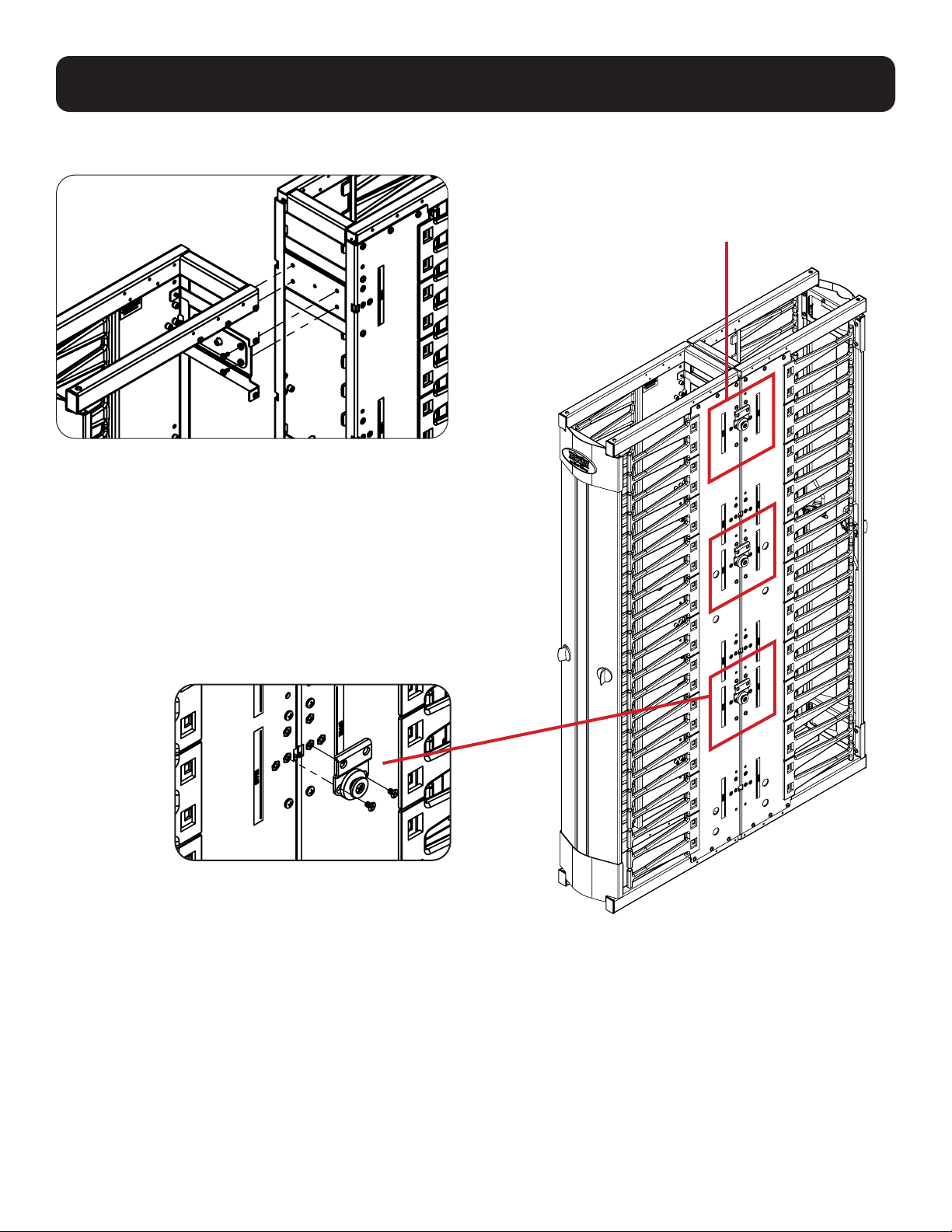
5
Single-Depth Installation
1. Using M4 x 6 mm Flat Head Screws, attach the Mounting Brackets to the Side Panels.
Note: The Mounting Brackets should align with the labels on the side brackets.
2. Using M4 x 12 mm Pan Head Screws, attach the Mounting Buttons to the Mounting Brackets.
Mounted in
Location
Matching
Upper Label
Mounted in
Location
Matching
Upper Label
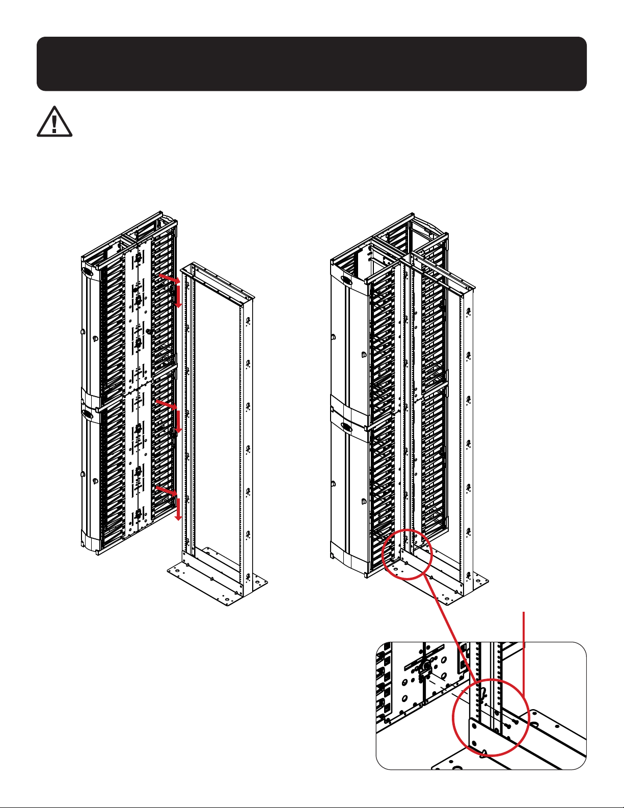
6
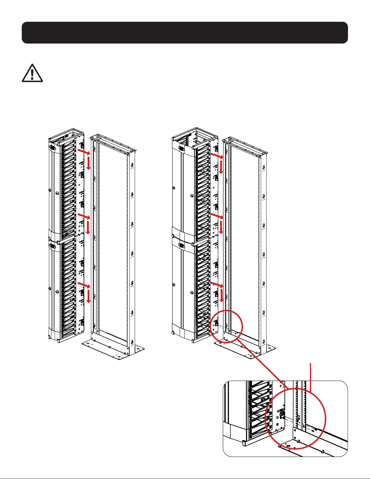
Installing Stacked Vertical Cable Ducts
onto Keyhole Mounting Slots
When hanging the vertical cable duct assembly onto the
keyhole mounting slots, make sure it is resting on the floor.
SRCABLEVRT6HD
SRCABLEVRT6HDFC
SRCABLEVRT12HD
Use M4 x 12 mm Pan
Head Screws inside of
the rack to fasten the
Cable Manager in place.

7
Joining Vertical Cable Ducts Back-to-Back
Use the Cross Brackets and
PDU Buttons to span both
vertical cable ducts.
Remove the Tie Plates from one side of the cable ducts
and use the M4 x 8 mm Tap Screws to attach to the
adjoining cable ducts.
Using M4 x 6 mm Flat Head Screws, attach
the Mounting Brackets to the Side Panel.
Note: Mounting Brackets should align with
the labels on the side brackets.
2. Using M4 x 12 mm Pan Head Screws,
attach the Mounting Buttons to the
Mounting Brackets.

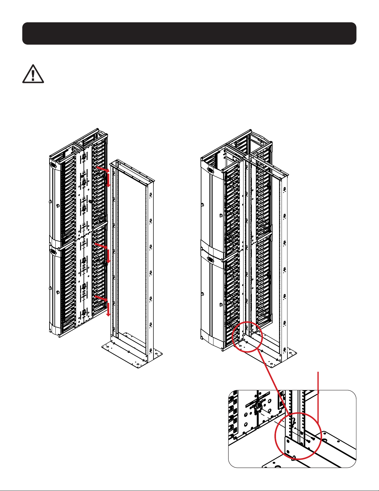
8
Installing Stacked Vertical Cable Ducts
onto Keyhole Mounting Slots
SRCABLEVRT6HD
SRCABLEVRT6HDFC SRCABLEVRT12HD
When hanging the vertical cable duct assembly onto the
keyhole mounting slots, make sure it is resting on the floor.
Use M4 x 12 mm
Pan Head Screws
inside of the rack
to fasten the cable
manager in place.

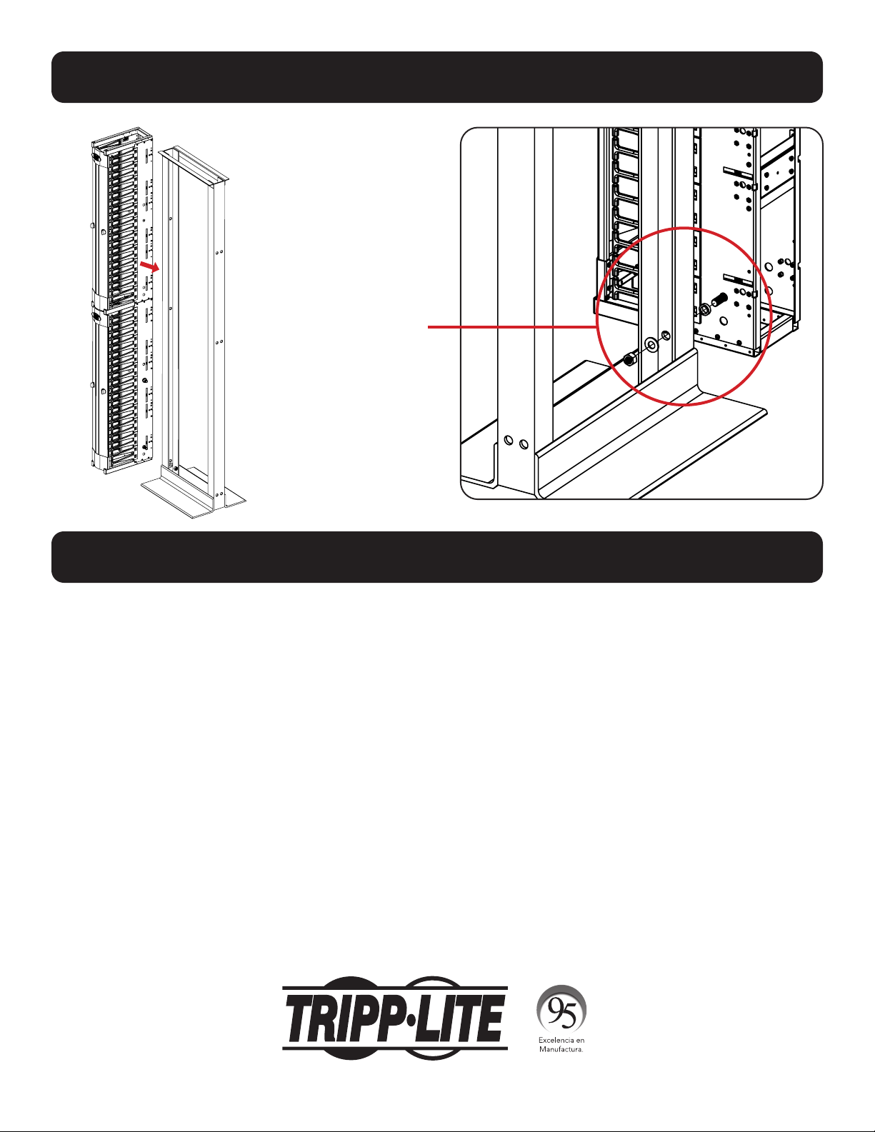
9
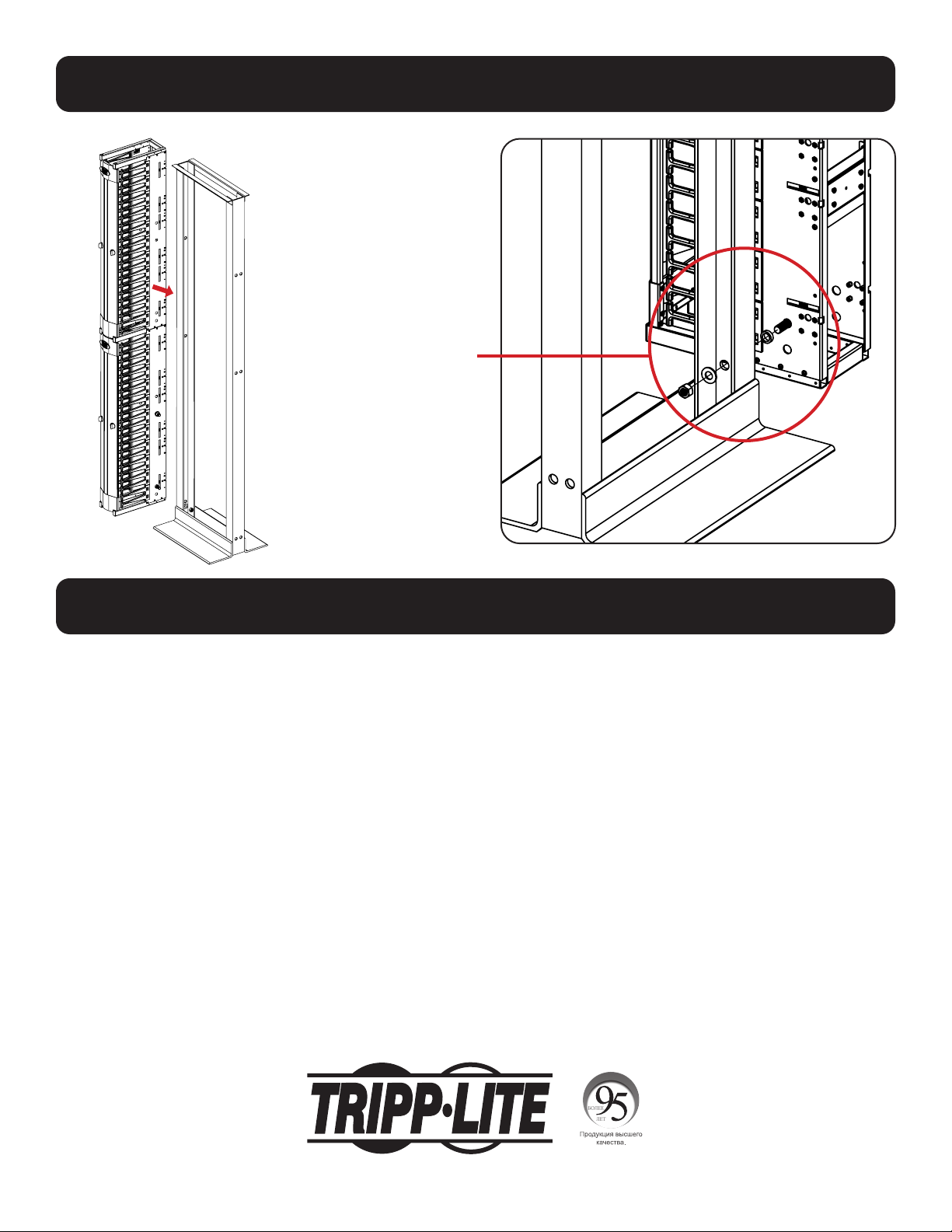
Alternate Rack Mounting
Warranty & Product Registration
1111 W. 35th Street, Chicago, IL 60609 USA • tripplite.com/support
5-Year Limited Warranty
Seller warrants this product, if used in accordance with all applicable instructions, to be free from original defects in material and
workmanship for a period of 5 years from the date of initial purchase. If the product should prove defective in material or workmanship within
that period, Seller will repair or replace the product, at its sole discretion.
THIS WARRANTY DOES NOT APPLY TO NORMAL WEAR OR TO DAMAGE RESULTING FROM ACCIDENT, MISUSE, ABUSE OR NEGLECT. SELLER
MAKES NO EXPRESS WARRANTIES OTHER THAN THE WARRANTY EXPRESSLY SET FORTH HEREIN. EXCEPT TO THE EXTENT PROHIBITED BY
APPLICABLE LAW, ALL IMPLIED WARRANTIES, INCLUDING ALL WARRANTIES OF MERCHANTABILITY OR FITNESS, ARE LIMITED IN DURATION
TO THE WARRANTY PERIOD SET FORTH ABOVE; AND THIS WARRANTY EXPRESSLY EXCLUDES ALL INCIDENTAL AND CONSEQUENTIAL
DAMAGES. (Some states do not allow limitations on how long an implied warranty lasts, and some states do not allow the exclusion or
limitation of incidental or consequential damages, so the above limitations or exclusions may not apply to you. This warranty gives you
specific legal rights, and you may have other rights which vary from jurisdiction to jurisdiction.)
WARNING: The individual user should take care to determine prior to use whether this device is suitable, adequate or safe for the use
intended. Since individual applications are subject to great variation, the manufacturer makes no representation or warranty as to the
suitability or fitness of these devices for any specific application.
Product Registration
Visit tripplite.com/warranty today to register the warranty for your new Tripp Lite product. You’ll be automatically entered into a drawing for
a chance to win a FREE Tripp Lite product!*
* No purchase necessary. Void where prohibited. Some restrictions apply. See website for details.
Tripp Lite has a policy of continuous improvement. Specifications are subject to change without notice. Photos and illustrations may differ
slightly from actual products.
20-10-111 93-3D23_RevA
For alternate structures,
attach the vertical cable
duct with ½” bolts, nuts,
washers and spacers in a
minimum of two places.
10
MÁS DE
AÑOS
Manual del Propietario
Administradores Verticales de
Cables SmartRack
®
Premium
Modelos de 6": SRCABLEVRT6HD, SRCABLEVRT6HDFC,
SRCABLEVRT6HD2
Modelos de 12": SRCABLEVRT12HD, SRCABLEVRT12HD2
1111 W. 35th Street, Chicago, IL 60609 EE UU • tripplite.com/support
Copyright © 2021 Tripp Lite. Todos los derechos reservados.
English 1 • Français 19 • Русский 28
11
Ensamble
Item
Nº
Descripción
Cantidad:
SRCABLEVRT6HD,
SRCABLEVRT6HDFC
Cantidad:
SRCABLEVRT6HD2,
SRCABLEVRT6HD2F
1
Conjunto de Puerta 2 4
2
Marco Soldado 4 8
3
Placa de Anclaje 6 12
4
Soporte Transversal 6 12
5
Panel Lateral Izquierdo 2 4
6
Panel Lateral Derecho 2 4
7
Tornillo de Cabeza Plana
M4 x 6 mm
6 12
8
Tornillo de Rosca
M4 x 8 mm
50 100
9
Tornillo de Cabeza Redonda
M4 x 6 mm
24 48
10
Buje de Puerta 8 16
11* Tornillo de Cabeza Redonda
M4 x 12 mm
18 36
12* Botón de Instalación 6 12
13* Soporte de Instalación 6 8
14**
Tornillo Hexagonal de 1/2" 4 8
15**
Tuerca Hexagonal de 1/2" 4 8
16**
Espaciador Metálico 4 8
17**
Arandela de 1/2" 4 8
6
3
2
8
10
9 8
Al ensamblar, tenga en cuenta la
orientación de los paneles laterales.
Las etiquetas “inferior”
deben estar
orientadas
sobre la parte inferior.
7
8
4
1
*No se Muestra: Para detalles, refiérase a Instalación de una sola Profundidad.
**No se Muestra: Para detalles, refiérase a Instalación en Rack Alterna.

12
Al ensamblar, tenga en cuenta la orientación de los Soportes Cruzados.
Si las unidades van a apilarse verticalmente, el conducto superior del cable debe tener los Soportes
Cruzados y los Botones del PDU instalados en las posiciones superiores, haciendo coincidir las eti-
quetas en los soportes laterales.
Ensamble
Configurado para
instalación inferior
Configurado para
instalación superior
13
Apilado de Conductos Verticales para Cable
Los conductos de cable
superior e inferior compartirán
una soldadura cuando se unan
verticalmente.
Notas
• Al ensamblar para uso en configuraciones verticales apiladas, no se usa uno de los marcos soldados del bastidor.
• Los paneles laterales se unen al marco Soldado del otro conducto de cable.
• Retire los bujes de la puerta del marco soldado sin usar y colóquelos en la soldadura del otro
conducto de cable para permitir la instalación de la puerta.
Coloque aquí
los Bujes de la
Puerta
Una de los
marcos soldados
no se usará
cuando se unan
verticalmente
a los paneles
laterales.
Usando (6) Tornillos
de Rosca M4 x 8
mm, fije los paneles
laterales del
conducto superior del
cable a la soldadura
del conducto inferior.
14
Instalación de una Sola Profundidad
1. Usando tornillos de cabeza plana M4 x 6 mm, fije los soportes de instalación a los paneles laterales.
Nota: Los soportes de instalación deben alinearse con las etiquetas en los soportes laterales.
2. Usando tornillos de cabeza plana M4 x 12 mm, fije los botones de instalación a los soportes de instalación.
Instalado en
la Etiqueta
Superior de
Concordancia de
Ubicación
Instalado en
la Etiqueta
Superior de
Concordancia de
Ubicación

15
Instalación de los Conductos de Cable Verticales
Apilados en las Ranuras de Instalación con Perforaciones
Al colgar el conjunto del conducto vertical del cable en las
ranuras de instalación con perforaciones, asegúrese de que esté apoyado en el piso.
SRCABLEVRT6HD
SRCABLEVRT6HDFC
SRCABLEVRT12HD
Use Tornillos de Cabeza
Redonda M4 x 12 mm
dentro del rack para
sujetar el Administrador
de Cables en su lugar.
16
Unión Espalda con Espalda de Conductos de Cable Verticales
Use los soportes transversales y
los botones del PDU para espaciar
ambos conductos
de cable verticales.
Retire las placas de anclaje de un lado de los conductos
de cable y use los Tornillos de Rosca M4 x 8 mm para fijar
a los conductos de cable adyacentes.
Usando Tornillos de Cabeza Plana M4 x 6
mm, fije los Soportes de Instalación al
Panel Lateral.
Nota: Los Soportes de Instalación deben
alinearse con las etiquetas sobre los
soportes laterales.
2. Usando Tornillos de Cabeza Plana
M4 x 12 mm, fije los Botones de
Instalación a los Soportes de Instalación.
17
Instalación de los Conductos de Cable Verticales
Apilados en las Ranuras de Instalación con Perforaciones
SRCABLEVRT6HD
SRCABLEVRT6HDFC SRCABLEVRT12HD
Al colgar el conjunto del conducto vertical del cable en las
ranuras de instalación con perforaciones, asegúrese de que esté apoyado en el piso.
Use Tornillos de
Cabeza Redonda
M4 x 12 mm dentro
del rack para sujetar
el Administrador de
Cables en su lugar.
18
MÁS DE
AÑOS
Instalación en Rack Alterna
Garantía
1111 W. 35th Street, Chicago, IL 60609 EE UU • tripplite.com/support
Garantía Limitada por 5 Años
El vendedor garantiza este producto, si se usa de acuerdo con todas las instrucciones aplicables, de que está libre de defectos en cuanto
a materiales y mano de obra por un período de 5 años a partir de la fecha de compra inicial. Si el producto resulta defectuoso en cuanto a
materiales o mano de obra dentro de ese período, el vendedor reparará o reemplazará el producto a su entera discreción.
ESTA GARANTÍA NO SE APLICA AL DESGASTE NORMAL O A LOS DAÑOS QUE RESULTEN DE ACCIDENTES, USO INCORRECTO, USO
INDEBIDO O NEGLIGENCIA. EL VENDEDOR NO OTORGA GARANTÍAS EXPRESAS DISTINTAS A LA ESTIPULADA EN EL PRESENTE. SALVO EN
LA MEDIDA EN QUE LO PROHÍBAN LAS LEYES APLICABLES, TODAS LAS GARANTÍAS IMPLÍCITAS, INCLUIDAS TODAS LAS GARANTÍAS DE
COMERCIALIZACIÓN O IDONEIDAD, ESTÁN LIMITADAS EN CUANTO A DURACIÓN AL PERÍODO DE GARANTÍA ESTABLECIDO; ASIMISMO,
ESTA GARANTÍA EXCLUYE EXPRESAMENTE TODOS LOS DAÑOS INCIDENTALES E INDIRECTOS. (Algunos estados no permiten limitaciones en
cuanto a la duración de una garantía y algunos estados no permiten la exclusión o limitación de daños incidentales o indirectos, de modo
que es posible que las limitaciones anteriores no se apliquen a usted. Esta garantía le otorga derechos legales específicos y es posible que
usted goce de otros derechos que pueden variar de una jurisdicción a otra).
ADVERTENCIA: antes de usarlo, cada usuario debe tener cuidado al determinar si este dispositivo es adecuado o seguro para el uso
previsto. Ya que las aplicaciones individuales están sujetas a gran variación, el fabricante no garantiza la adecuación de estos dispositivos
para alguna aplicación específica.
Tripp Lite tiene una política de mejora continua. Las especificaciones están sujetas a cambio sin previo aviso. Las fotografías e ilustraciones
pueden diferir ligeramente de los productos reales.
20-10-111 93-3D23_RevA
Para estructuras alternas,
fije el conducto vertical del
cable con tornillos, tuercas,
arandelas y espaciadores
de ½” al mínimo en dos
lugares.
19
Manuel de l'utilisateur
Gestionnaires de câbles verticaux
de haute qualité SmartRack
®
Modèles de 15,24 cm (6 po) :
SRCABLEVRT6HD, SRCABLEVRT6HDFC, SRCABLEVRT6HD2
Modèles de 30,48 cm (12 po) :
SRCABLEVRT12HD, SRCABLEVRT12HD2
1111 W. 35th Street, Chicago, IL 60609 USA • tripplite.com/support
Droits d'auteur © 2021 Tripp Lite. Tous droits réservés.
English 1 • Español 10 • Русский 28
20
Assemblage
Code
d'article
Description
Qté : SRCABLEVRT6HD,
SRCABLEVRT6HDFC
Qté : SRCABLEVRT6HD2,
SRCABLEVRT6HD2F
1
Ensemble de porte 2 4
2
Ensemble soudé 4 8
3
Plaque d'attache 6 12
4
Traverse 6 12
5
Panneau latéral
gauche
2. 4
6
Panneau latéral droit 2 4
7
Vis à tête plate
M4 x 6 mm
6 12
8
Vis filetée M4 x 8 mm
50 100
9
Vis à tête cylindrique
bombée M4 x 8 mm
24 48
10
Douille de porte 8 16
11*
Vis à tête cylindrique
bombée M4 x 12 mm
18 36
12* Bouton de montage 6 12
13*
Support de montage
6 8
14** Boulon hexagonal de
1,27 cm (1/2 po)
4 8
15** Écrou hexagonal de
1,27 cm (1/2 po)
4 8
16** Entretoise en métal
4 8
17** Rondelle de
1,27 cm (1/2 po)
4 8
6
3
2
8
10
9 8
Lors de l'assemblage, prendre note de
l'orientation des panneaux latéraux.
Les étiquettes « lower » (plus bas)
doivent être orientées
vers le bas.
7
8
4
1
*Non illustré : Consulter Installation à profondeur unique pour plus de détails.
**Non illustré : ConsulterMontage en bâti alternatif pour plus de détails.

21
Lors de l'assemblage, prendre note de l'orientation des traverses.
Si les appareils seront empilés verticalement, les traverses et les boutons de la PDU du conduit de
câble supérieur doivent être montés dans l'une des positions supérieures qui correspond aux étiquettes
sur les supports latéraux.
Assemblage
Configuré pour un montage
plus bas
Configuré pour un
montage plus haut

22
Empiler des conduits de câbles verticaux
Les conduits de câbles
supérieur et inférieur
partageront un ensemble
soudé lorsqu'ils sont joints
verticalement.
Remarques
• Lors d'un assemblage pour une utilisation dans des configurations verticales empilées, l'un des ensembles soudés
du cadre n'est pas utilisé.
• Les panneaux latéraux sont joints à l'ensemble soudé de l'autre conduit de câbles.
• Retirer les douilles de porte de l'ensemble soudé non utilisé, puis les placer dans l'ensemble soudé de l'autre
conduit de câbles pour permettre l'installation de la porte.
Placer les
douilles de
porte ici.
Un des
ensembles
soudés ne sera
pas utilisé
pour joindre
verticalement
les panneaux
latéraux.
À l'aide de (6) vis
filetées M4 x 8 mm,
fixer les panneaux
latéraux du conduit
de câbles supérieur à
l'ensemble soudé du
conduit inférieur.

23
Installation à profondeur unique
1. À l'aide de vis à tête plate M4 x 6 mm, fixer les supports de montage aux panneaux latéraux.
Remarque : Les supports de montage devraient être alignés avec les étiquettes sur les supports latéraux.
2. À l'aide de vis mécaniques à tête cylindrique M4 x 12 mm, fixer les boutons de montage aux supports de montage.
Monté à
l'emplacement
correspondant
à l'étiquette
supérieure
Monté à
l'emplacement
correspondant
à l'étiquette
supérieure

24
Installation de conduits de câbles verticaux empilés
sur les fentes de montage en trou de serrure
Lorsque l'ensemble du conduit de câbles vertical est suspendu aux
fentes de montage en trou de serrure, s'assurer qu'il repose sur le plancher.
SRCABLEVRT6HD
SRCABLEVRT6HDFC
SRCABLEVRT12HD
Utiliser les vis
mécaniques à tête
cylindrique M4 x 12 mm
à l'intérieur du bâti pour
fixer le gestionnaire de
câbles en place.

25
Joindre les conduits de câbles verticaux dos à dos
Utiliser les traverses et les
boutons de la PDU pour
couvrir les deux conduits de
câbles verticaux.
Retirer les plaques d'attache de l'un des côtés des conduits
de câbles, puis utiliser les vis filetées M4 x 8 mm pour les
fixer aux conduits de câbles adjacents.
À l'aide de vis à tête plate M4 x 6 mm, fixer
les supports de montage au panneau latéral.
Remarque : Les supports de montage
devraient être alignés avec les étiquettes sur
les supports latéraux.
2. À l'aide de vis mécaniques à tête
cylindrique M4 x 12 mm, fixer les boutons de
montage aux supports de montage.

26
Installation de conduits de câbles verticaux empilés
sur les fentes de montage en trou de serrure
SRCABLEVRT6HD
SRCABLEVRT6HDFC SRCABLEVRT12HD
Lorsque l'ensemble du conduit de câbles vertical est suspendu aux
fentes de montage en trou de serrure, s'assurer qu'il repose sur le plancher.
Utiliser les vis
mécaniques à tête
cylindrique M4 x
12 mm à l'intérieur
du bâti pour fixer
le gestionnaire de
câbles en place.

27
Montage en bâti alternatif
Garantie
1111 W. 35th Street, Chicago, IL 60609 USA • tripplite.com/support
Garantie limitée de 5 ans
Le vendeur garantit ce produit, s'il est utilisé conformément à toutes les instructions applicables, est exempt de tous défauts de matériaux et
de fabrication pour une période de 5 ans à partir de la date d'achat initiale. Si le produit s'avère défectueux en raison d'un vice de matériau
ou de fabrication au cours de cette période, le vendeur s'engage à réparer ou remplacer le produit, à son entière discrétion.
CETTE GARANTIE NE S'APPLIQUE PAS À L'USURE NORMALE OU AUX DOMMAGES RÉSULTANT D'UNE MAUVAISE UTILISATION, D'UN ABUS OU
D'UNE NÉGLIGENCE. LE VENDEUR N'ACCORDE AUCUNE GARANTIE EXPRESSE AUTRE QUE LA GARANTIE EXPRESSÉMENT DÉCRITE DANS LE
PRÉSENT DOCUMENT. SAUF DANS LA MESURE OÙ CELA EST INTERDIT PAR LA LOI EN VIGUEUR, TOUTE GARANTIE IMPLICITE, Y COMPRIS
TOUTES LES GARANTIES DE QUALITÉ MARCHANDE OU D'ADAPTATION, SONT LIMITÉES À LA PÉRIODE DE GARANTIE CI-DESSUS ET CETTE
GARANTIE EXCLUT EXPRESSÉMENT TOUS DOMMAGES DIRECTS ET INDIRECTS. (Certains États ne permettent pas de limitations sur la durée
d'une garantie implicite, et certains États ne permettent pas l'exclusion ou la limitation des dommages fortuits ou consécutifs, de sorte que
les limitations ou exclusions susmentionnées peuvent ne pas s'appliquer à vous. Cette garantie vous accorde des droits légaux spécifiques,
et vous pouvez avoir d'autres droits qui varient d'une compétence à l'autre.)
AVERTISSEMENT : L'utilisateur individuel doit prendre soin de déterminer avant l'utilisation si cet appareil est approprié, adéquat et sûr pour
l'usage prévu. Puisque les utilisations individuelles sont sujettes à des variations importantes, le fabricant ne fait aucune déclaration ou
garantie quant à l'aptitude ou l'adaptation de ces dispositifs pour une application spécifique.
La politique de Tripp Lite en est une d'amélioration continue. Les caractéristiques techniques sont modifiables sans préavis. Les produits
réels peuvent différer légèrement des photos et des illustrations.
20-10-111 93-3D23_RevA
Pour des structures
alternatives, fixer le
conduit de câbles vertical
avec des boutons, des
écrous, des rondelles et
des entretoises de
1,27 cm (½ po) à au
moins deux endroits.

28
Руководcтво пользoвателя
Вертикальные кабельные организаторы
SmartRack
®
Premium
6-дюймовые модели: SRCABLEVRT6HD, SRCABLEVRT6HDFC, SRCABLEVRT6HD2
12-дюймовые модели: SRCABLEVRT12HD, SRCABLEVRT12HD2
1111 W. 35th Street, Chicago, IL 60609 USA • tripplite.com/support
Охраняется авторским правом © 2021 Tripp Lite. Перепечатка запрещается.
English 1 • Español 10 • Français 19
29
Порядок сборки
№
поз. Описание
К-во:
SRCABLEVRT6HD,
SRCABLEVRT6HDFC
К-во:
SRCABLEVRT6HD2,
SRCABLEVRT6HD2F
1
Дверца в сборе 2 4
2
Сварной кронштейн 4 8
3
Стыковая накладка 6 12
4
Поперечный кронштейн 6 12
5
Левая боковая панель 2 4
6
Правая боковая панель 2 4
7
Винт M4 x 6 мм
с потайной головкой
6 12
8
Винт крепежный
M4 x 8 мм
50 100
9
Винт M4 x 8 мм
с полукруглой головкой
24 48
10
Дверной фиксатор 8 16
11* Винт M4 x 12 мм
с полукруглой головкой
18 36
12* Монтажная защелка 6 12
13* Монтажный кронштейн 6 8
14** Болт шестигранный 1/2" 4 8
15** Гайка шестигранная 1/2" 4 8
16** Проставка
металлическая
4 8
17** Шайба 1/2" 4 8
6
3
2
8
10
9 8
В процессе сборки следует правильно
располагать боковые панели.
Метки "lower" ("низ")
должны
находиться
снизу.
7
8
4
1
*На рисунке не показано. Подробнее см. в разделе Однорядная установка.
**На рисунке не показано. Подробнее см. в разделе Другие варианты стоечного монтажа.
30
В процессе сборки следует правильно располагать поперечные кронштейны.
При вертикальном совмещении модулей поперечные кронштейны верхнего кабелепровода и защелки для крепления к PDU
должны быть установлены в верхних положениях согласно маркировке на боковых кронштейнах.
Порядок сборки
Расположение для
монтажа снизу
Расположение для
монтажа сверху

31
Установка вертикальных кабельных организаторов друг на друга
При вертикальном соединении верхний
и нижний кабелепроводы крепятся к
одному общему сварному кронштейну.
Примечания
• При вертикальной установке кабелепроводов друг на друга один из несущих сварных кронштейнов не используется.
• Боковые панели крепятся к сварному кронштейну другого кабелепровода.
• Снимите дверные фиксаторы с неиспользуемого сварного кронштейна и закрепите их на сварном кронштейне другого кабелепровода для установки дверцы.
Установите
дверные фиксаторы
здесь
При вертикальном
соединении боковых
панелей один из
сварных кронштейнов
не используется.
С помощью крепежных
винтов (6 шт.) M4 x 8 мм
прикрепите боковые панели
верхнего кабелепровода
к сварному кронштейну
нижнего кабелепровода.

32
Однорядная установка
1. Прикрепите монтажные кронштейны к боковым панелям при помощи винтов M4 x 6 мм с потайной головкой.
Примечание. Монтажные кронштейны должны совмещаться с соответствующими метками на боковых панелях.
2. Прикрепите монтажные защелки к монтажным кронштейнам при помощи винтов M4 x 12 мм с полукруглой головкой.
Прикрепленные
кронштейны
должны быть
совмещены с
верхней меткой
Прикрепленные
кронштейны
должны быть
совмещены с
верхней меткой
33
Установка скрепленных вертикальных кабелепроводов в монтажные пазы
При навешивании сборной конструкции из вертикальных кабелепроводов с использованием
монтажных пазов следует убедиться в том, что она опирается на пол.
SRCABLEVRT6HD
SRCABLEVRT6HDFC
SRCABLEVRT12HD
Прикрепите кабельный
организатор с помощью винтов
M4 x 12 мм с полукруглой
головкой, ввертываемых
изнутри стойки.

34
Скрепление вертикальных кабелепроводов тыльными сторонами
Для соединения двух вертикальных
кабелепроводов следует использовать
поперечные кронштейны и защелки
для монтажа PDU, скрепляющие их
между собой.
Снимите стыковые накладки с одной стороны кабелепроводов и скрепите
примыкающие друг к другу кабелепроводы с использованием крепежных
винтов M4 x 8 мм.
Прикрепите монтажные кронштейны к боковой панели при
помощи винтов M4 x 6 мм с потайной головкой.
Примечание. Монтажные кронштейны должны
совмещаться с соответствующими метками на боковых
панелях.
2. Прикрепите монтажные защелки к монтажным
кронштейнам при помощи винтов M4 x 12 мм с
полукруглой головкой.
35
Установка скрепленных вертикальных кабелепроводов в монтажные пазы
SRCABLEVRT6HD
SRCABLEVRT6HDFC SRCABLEVRT12HD
При навешивании сборной конструкции из вертикальных кабелепроводов с использованием
монтажных пазов следует убедиться в том, что она опирается на пол.
Прикрепите кабельный
организатор с помощью
винтов M4 x 12 мм с
полукруглой головкой,
ввертываемых изнутри
стойки.
36
Другие варианты стоечного монтажа
Гарантийные обязательства
1111 W. 35th Street, Chicago, IL 60609 USA • tripplite.com/support
Условия 5-летней ограниченной гарантии
Продавец гарантирует отсутствие изначальных дефектов материала или изготовления в течение 5 лет с момента первоначальной покупки данного изделия при условии его
использования в соответствии со всеми применимыми к нему указаниями. В случае проявления каких-либо дефектов материала или изготовления в течение указанного периода
Продавец осуществляет ремонт или замену данного изделия исключительно по своему усмотрению.
ДЕЙСТВИЕ НАСТОЯЩЕЙ ГАРАНТИИ НЕ РАСПРОСТРАНЯЕТСЯ НА СЛУЧАИ ЕСТЕСТВЕННОГО ИЗНОСА ИЛИ ПОВРЕЖДЕНИЯ В РЕЗУЛЬТАТЕ АВАРИИ, НЕНАДЛЕЖАЩЕГО ИСПОЛЬЗОВАНИЯ, НАРУШЕНИЯ
ПРАВИЛ ЭКСПЛУАТАЦИИ ИЛИ ХАЛАТНОСТИ. ПРОДАВЕЦ НЕ ПРЕДОСТАВЛЯЕТ НИКАКИХ ЯВНО ВЫРАЖЕННЫХ ГАРАНТИЙ ЗА ИCКЛЮЧЕНИЕМ ПРЯМО ИЗЛОЖЕННОЙ В НАCTОЯЩЕМ ДОКУМЕНТЕ.
ЗА ИСКЛЮЧЕНИЕМ СЛУЧАЕВ, ЗАПРЕЩЕННЫХ ДЕЙСТВУЮЩИМ ЗАКОНОДАТЕЛЬСТВОМ, ВСЕ ПОДРАЗУМЕВАЕМЫЕ ГАРАНТИИ, ВКЛЮЧАЯ ВСЕ ГАРАНТИИ ПРИГОДНОСТИ ДЛЯ ПРОДАЖИ ИЛИ
ИСПОЛЬЗОВАНИЯ ПО НАЗНАЧЕНИЮ, ОГРАНИЧЕНЫ ПО ПРОДОЛЖИТЕЛЬНОСТИ ДЕЙСТВИЯ ВЫШEУКАЗАННЫМ ГАРАНТИЙНЫМ СРОКОМ; КРОМЕ ТОГО, ИЗ НАСТОЯЩЕЙ ГАРАНТИИ ЯВНЫМ
ОБРАЗОМ ИСКЛЮЧАЮТСЯ ВСЕ ПОБОЧНЫЕ, СЛУЧАЙНЫЕ И КОСВЕННЫЕ УБЫТКИ. (В некоторых штатах не допускается введение ограничений на продолжительность действия тех или иных
подразумеваемых гарантий, а в некоторых - исключение или ограничение размера побочных или косвенных убытков. В этих случаях вышеизложенные ограничения или исключения
могут на вас не распространяться. Настоящая гарантия предоставляет конкретные юридические права, а набор других прав может быть различным в зависимости от юрисдикции).
ВНИМАНИЕ! До начала использования данного устройства пользователь должен убедиться в том, что оно является пригодным, соответствующим или безопасным для
предполагаемого применения. В связи с большим разнообразием конкретных применений производитель не дает каких-либо заверений или гарантий относительно пригодности
данных изделий для какого-либо конкретного применения или их соответствия каким-либо конкретным требованиям.
Компания Tripp Lite постоянно совершенствует свою продукцию. B cвязи с этим возможно изменение технических характеристик без предварительного уведoмления. Внeшний вид
реальных изделий может несколько отличаться от представленного на фотографиях и иллюстрацияx.
20-10-111 93-3D23_RevA
При использовании других типов
конструкций следует прикрепить
вертикальный кабелепровод
с помощью болтов, гаек, шайб и
проставок размером ½"
как минимум в двух местах.