
ONLINE: TRINITYAPPLIANCES.COM.AU
P a g e |
9
User Manual
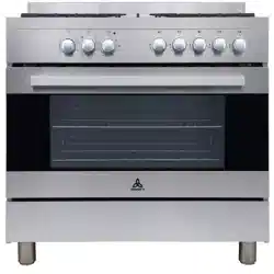
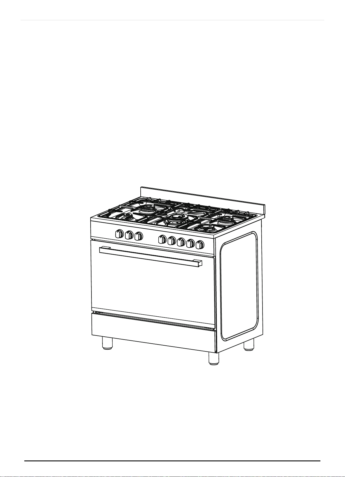
90 CM FREESTANDING ELECTRIC OVEN WITH GAS COOKTOP
MODEL: TRFSEGO900
Please read this manual carefully before using, and keep it for future reference.
INSTRUCTION MANUAL
90 cm Freestanding Electric Oven with Gas Cooktop
Models: TRFSEGO900
ONLINE: TRINITYAPPLIANCES.COM.AU
P a g e |
2

CONTENTS
1 PACKAGE
..........................................................................................................................................................................
5
1.1 IMPORTANT - CHECK FOR ANY DAMAGE OR MARKS
....................................................................................
5
1.2 HANDLING
.................................................................................................................................................................
5
1.3 BEFORE USING YOUR NEW APPLIANCE
..............................................................................................................
5
2 SAFETY WARNINGS
..........................................................................................................................................................
6
2.1 ATTENTION
..................................................................................................................................................................
6
2.2 WARNINGS
.................................................................................................................................................................
6
2.3 WHEN YOU CALL FOR SERVICE
............................................................................................................................
6
3 INSTALLING INSTRUCTION
..............................................................................................................................................
7
3.1 OVERALL DIMENSIONS
............................................................................................................................................
7
3.2 PROVISION FOR VENTILATION
............................................................................................................................
7
3.3 POSITIONING
.............................................................................................................................................................
8
3.4 CLEARANCES TO COMBUSTIBLE MATERIALS
.....................................................................................................
8
3.5 CLEARANCES TO NON-COMBUSTIBLE MATERIALS
..........................................................................................
8
3.6 FITTING THE SPLASH GUARD
..................................................................................................................................
9
3.7 STABILITY BRACKET
.................................................................................................................................................
11
3.8 GAS CONNECTION
...............................................................................................................................................
11
3.9 THE HOSE ASSEMBLY
..............................................................................................................................................
12
3.10 VERY IMPORTANT FOR THE INSTALLER
............................................................................................................
13
3.11 GAS CONVERSION AND ADJUSTMENT
..........................................................................................................
13
3.12 GAS ADJUSTEMENTS
..........................................................................................................................................
13
3.13 REPLACEMENT OF THE INJECTORS
..................................................................................................................
14
3.14 SPECIAL NOTE
.......................................................................................................................................................
14
3.15 MINIMUM FLOW ADJUSTMENT FOR HOB-TOPTAPS
.....................................................................................
15
3.16 ELECTRICAL CONNECTION
...............................................................................................................................
15
3.17 IMPORTANT INFO FOR ELECTRICAL PART
......................................................................................................
15
4 USING INSTRUCTION
.....................................................................................................................................................
16
4.1 WARNING:
...............................................................................................................................................................
16
4.2 - 1 MINUTE TOUR -
..................................................................................................................................................
17
4.3 HOW TO USE YOUR ELECTRIC OVEN
................................................................................................................
18
4.4 MULTIFUNCTION OVEN
.........................................................................................................................................
18
4.5 GENERAL INSTRUCTION
........................................................................................................................................
21
4.6 GUIDE FOR CONVENTIONAL COOKING (BAKE)
...........................................................................................
21
4.7 PLATE WARMING
....................................................................................................................................................
23
ONLINE: TRINITYAPPLIANCES.COM.AU
P a g e |
3

4.8 GUIDE FOR FORCED CONVECTION COOKING
............................................................................................
23
4.9 USING THE GRILL
.....................................................................................................................................................
24
4.10 INSTRUCTION FOR USE OF CONTROL DEVICES
............................................................................................
25
4.11 OPERATION PANEL AND INSTRUCTIONS
........................................................................................................
25
4.12 CONTROL FUNCTION AND INSTRUCTIONS
....................................................................................................
26
4.13 CONTROL KNOB FOR MINUTE MINDER
..........................................................................................................
28
4.14 ACCESSORIES
.......................................................................................................................................................
29
ACCESSORYDESCRIPTION
..........................................................................................................................................
29
4.15 USE OF THE ELECTRIC GRILL
..............................................................................................................................
29
4.16 USING THE ROTISSERIE
.........................................................................................................................................
30
4.17 INSERTING THE ROTISSERIE
.................................................................................................................................
30
4.18 REMOVING THE ROTARY SPIT
............................................................................................................................
31
5 CLEANING
.......................................................................................................................................................................
32
5.1 NOTE
..........................................................................................................................................................................
32
5.2 PAN SUPPORTS AND BURNERS
............................................................................................................................
32
5.3 DAILY CLEANING
...................................................................................................................................................
33
5.4 CLEANING THE INTERIOR GLASS OF THE OVEN
..............................................................................................
35
5.5 THE INNER GLASS OF THE OVEN WITH FIXING SNAP
.....................................................................................
35
5.6 REMOVAL OF OVEN DOOR
................................................................................................................................
36
5.7 TELESCOPIC RAILS
..................................................................................................................................................
37
5.8 DISASSEMBLY OF WORK-TOP
..............................................................................................................................
37
5.9 GREASING OF TAPS
...............................................................................................................................................
38
5.10 TAP REPLACEMENT
..............................................................................................................................................
38
6 SOME SAFETY POINTS
...................................................................................................................................................
39
6.1 DO NOT USE THE APPLIANCE AS A SPACE HEATER. IF YOU SMELL GAS
..................................................
39
6.2 IF IN DIFFICULTY CALL EMERGENCY SERVICES.
..............................................................................................
39
6.3 FOR YOUR SAFETY AND THAT OF YOUR CHILDREN
.......................................................................................
39
7 TECHNICAL DATA
..........................................................................................................................................................
40
7.1 TECHNICAL DATA SHEET
.......................................................................................................................................
40
7.2 NOZZLES
....................................................................................................................................................................
41
8 PROBLEM SOLVER
.........................................................................................................................................................
42
8.1 PROBLEM MIGHT OCCURRED
............................................................................................................................
42
8.2 THINGS TO TRY BEFORE CALLING FOR SERVICE
.............................................................................................
42
9 DISPOSAL
.........................................................................................................................................................................
45
10 CUSTOMER CARE
........................................................................................................................................................
46
ONLINE: TRINITYAPPLIANCES.COM.AU
P a g e |
4

1
PACKAGE
1.1 IMPORTANT - CHECK FOR ANY DAMAGE OR MARKS
Please thoroughly inspect your goods
at the delivery time
, if you notice any damage to your
goods:
Please notify the delivery team at the time of delivery and
do NOT accept damaged
product
.
Please notify us immediately as the problem can be instantly solved and damaged
product return to the courier office.
When you open the package and find the appliance is damaged or marked, you must
report it within 24 hours. Do not install or connect the item, keep the package as original, if
you wish to claim for damage/marks under the manufacturer’s warranty. This does not
affect your statutory rights.
Evidence of damage will be required.
1.2 HANDLING
Do not use the door and/or handle to carry or move the appliance.
Carry out the movement and transportation in the original packaging.
Pay maximum attention to the appliance while loading/unloading and handling.
Make sure that the packaging is securely closed during handling and transportation.
Protect from external factors (such as humidity, water, etc.) that may damage the
packaging.
Be careful not to damage the appliance due to bumps, crashes, drops, etc. while
handling and transporting and not to break or deform it during operation.
1.3 BEFORE USING YOUR NEW APPLIANCE
Read this guide, taking special note of the ‘Safety Warnings’ section.
Remove any protective film that may still be on your appliance.
This instruction manual has been prepared jointly for multiple models. Some of the
specifications explained in the manual, may not be included in your appliance. Pay
attention to the explanations with illustrations while reading the manual.
NOTE:
This instruction manual has been prepared jointly for multiple models. Some of the
specifications explained in the manual, may be slightly different or not be included in your
appliance. Pay attention to the explanations with illustrations while reading the manual.
ONLINE: TRINITYAPPLIANCES.COM.AU
P a g e |
5

2 SAFETY WARNINGS
2.1 ATTENTION
This appliance must only be used for the purpose of domestic cooking.
Before using the appliance, do not forget to remove the
plastic protective film from parts of the appliance.
2.2 WARNINGS
Accessible parts will become hot when in use. To avoid burns and scalds children
should be kept away.
In order to prevent accidental tipping of the appliance, for example by a child
climbing onto the open oven door, the stabilizing means must be installed.
This appliance is not intended for use by persons (including children) with reduced
physical, sensory or mental capabilities, or lack of experience and knowledge, unless
they have been given supervision or instruction concerning use of the appliance by a
person responsible for their safety. Children should be supervised to ensure that they
do not play with the appliance.
Young children and infirm persons should not be left unsupervised in the vicinity of the
appliance.
Before you use the appliance for the first time, check that the plastic films protecting
some parts (fascia panel, parts in stainless steel, etc.) have been removed.
A steam cleaner is not to be used cleaning this appliances.
DO NOT USE OR STORE FLAMMABLE MATERIALS IN THE APPLIANCE STORAGE DRAWER
OR NEAR THIS APPLIANCE.
DO NOT SPRAY AEROSOLS IN THE VICINITY OF THIS APPLIANCE WHILE IT IS IN OPERATION.
DO NOT USE THIS APPLIANCE AS A SPACE HEATER DO NOT MODIFY THIS APPLIANCE.
2.3
WHEN YOU CALL FOR SERVICE
When you call for service or order parts for your unit, be sure to give:
MODEL
SERIAL NUMBER
COLOUR
PART NAME and/or description of problem
YOUR FULL NAME, ADDRESS, and HOME TELEPHONE NUMBER and BUSINESS TELEPHONE
NUMBER IF APPROPRIATE.
Servicing shall be carried out only by authorised personnel.
ONLINE: TRINITYAPPLIANCES.COM.AU
P a g e |
6
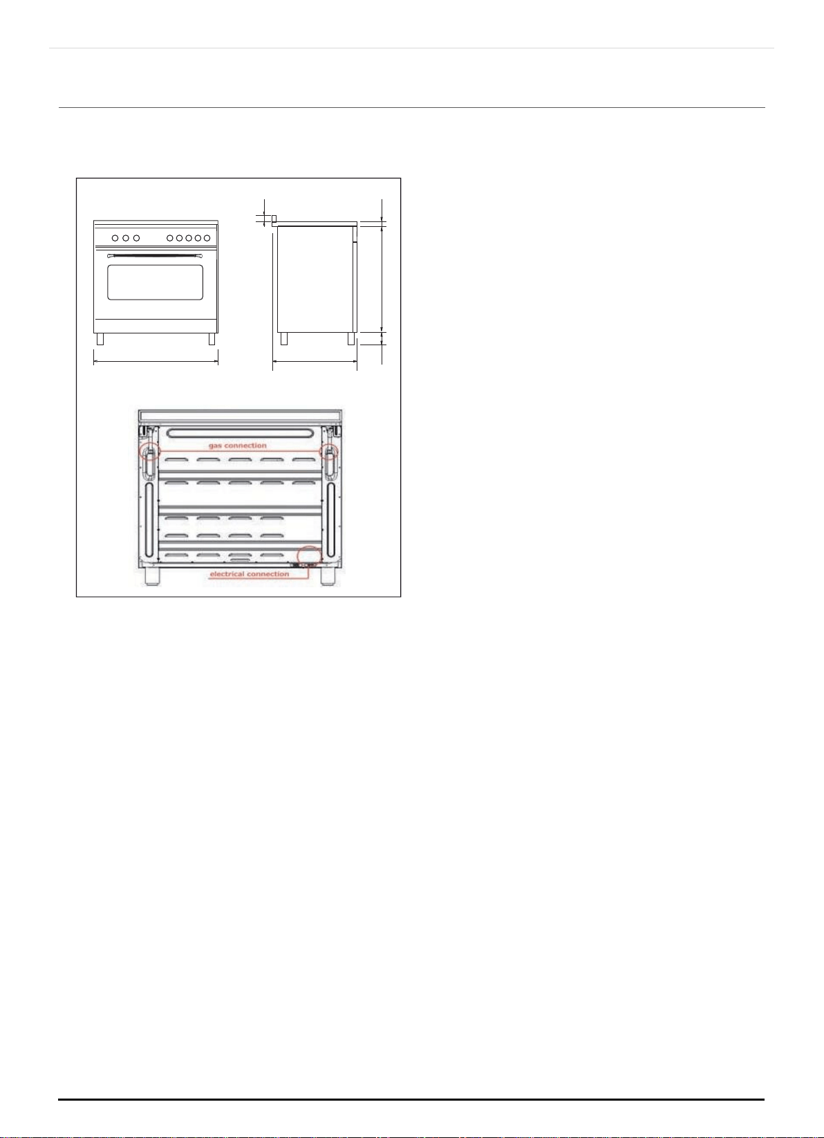
3 INSTALLING INSTRUCTION
3.1
OVERALL DIMENSIONS
3.2
PROVISION FOR VENTILATION
The room where the Cooker is installed should have permanent ventilation as
follows:
"Ventilation must be in accordance with AS5601/AG 601
Gas Installations. In general, the appliance should have adequate ventilation for
complete combustion of gas, proper flueing and to maintain temperature of
immediate surroundings within safe limits. "Do not install in a bed-sitting room, a
bathroom or shower room.
If there is another fuel burning appliance in the same room, a higher level of
ventilation will be required, you should consult
"the safety requirements".
In addition to the above, during prolonged use, opening a window in the same
room is recommended. This will avoid the build up of excessive moisture and
condensation.
ONLINE: TRINITYAPPLIANCES.COM.AU
B = adjustable height
(89/149mm)
595
895
B
729
60
22 or 40
P a g e |
7
3.3
POSITIONING
Important: Fix the chain located next to the gas connection on both sides of the
cooker to the rear wall to prevent the cooker from tilting. Both chains must be
securely fixed.
Make sure that the wall surface behind the Cooker is non-combustable (will not
catch fire).
Where a painted surface is adjacent, a fire retardent paint surface is
recommended. Wallpaper, wood, or fabric should not be used behind or next to
the cooker.
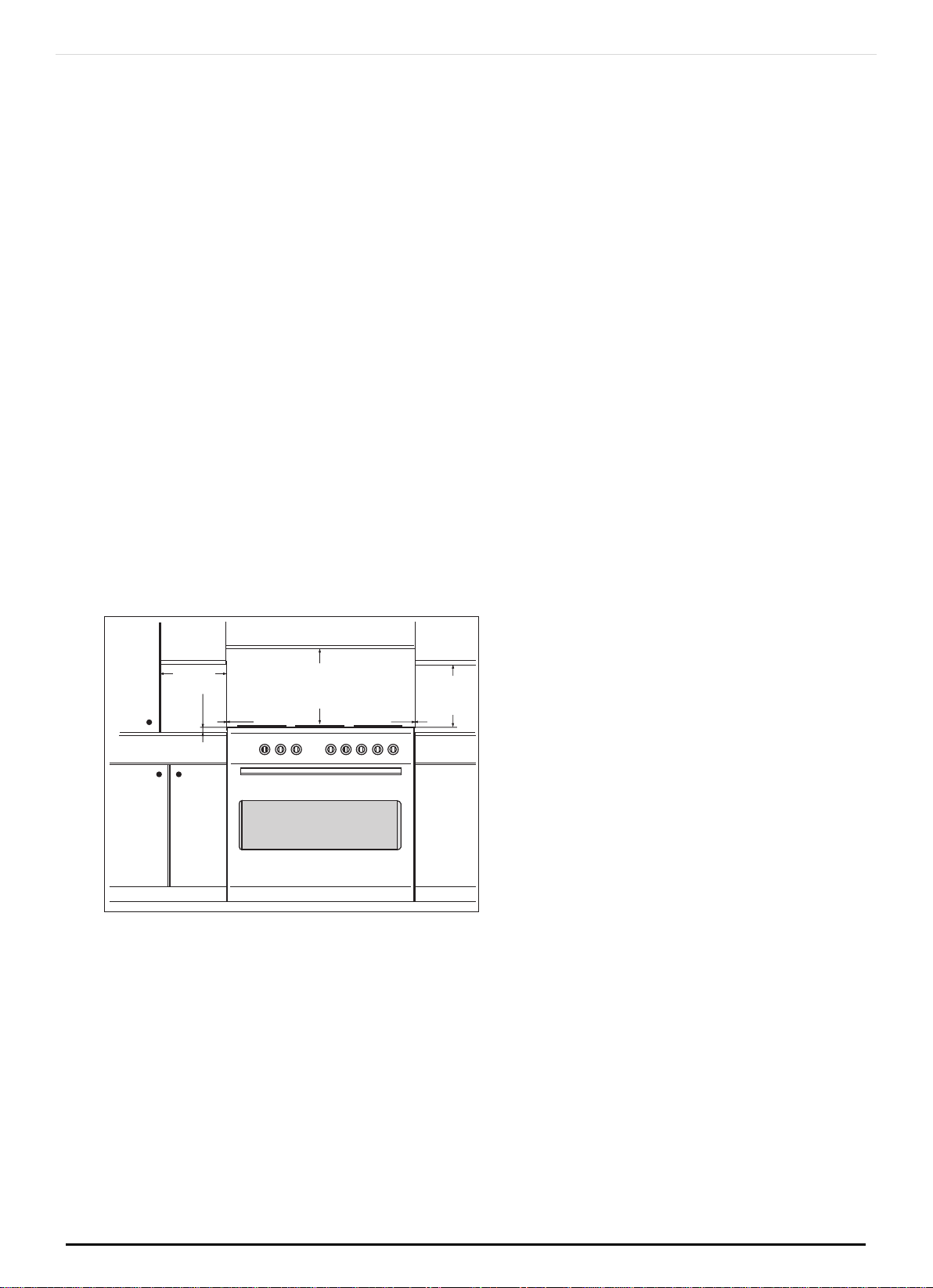
3.4 CLEARANCES TO COMBUSTIBLE MATERIALS
Any adjoining wall surface (side or rear) situated within 200mm of any hob burner
must be a suitable non-combustible material from the edge for a height of 150mm
for the entire length of the cooker.
Any combustible construction above the cooker must be at least 650mm above
the maintop. Ensure that a power and gas supply are nearby. The Cooker should be
located carefully so that the heat produced by it has plenty of space to escape.
The diagram below shows an ideal configuration.
No part of any adjoining wall surface can be made of combustible materials. The
protection of combustible materials required by Clause 5.12.1.1 of AS/NZS 5601 is
the fixing of 5 mm thick ceramic tiles to the surface or attaching fire resistant
material to the surface and covering with sheet metal with a minimum thickness of
0.4 mm.
3.5
CLEARANCES TO NON-COMBUSTIBLE MATERIALS
If the cooker is being fitted next to cupboards or adjoing wall surfaces, which are
within 200mm from the edge of the hob burner and of a suitable non-combustible
material as specified in AS/NZS 5601, then ensure that a distance of at least 60mm
ONLINE: TRINITYAPPLIANCES.COM.AU
min.100 mm
min. 650 mm
min. 400 mm
"0" mm
"0" mm
min.10 mm
P a g e |
8
is left between the edge of the cooker and the non-combustible material. This
gap is to allow plenty of space for the heat produced by the cooker to escape on
each side of the cooker.
Note:
The cooker is fitted with 4 legs for an eventual alignment in height with the furniture
( fig. 1 A ).
WARNING:
This appliance is not suitable to be installed on a base.
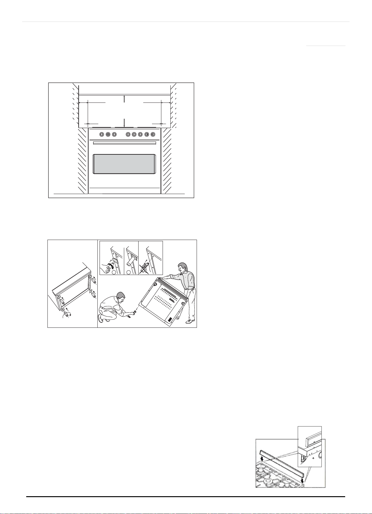
3.6
FITTING THE SPLASH GUARD
Depending on the model. Proceed as follows:
Remove the packaging and the protective film from the splash guard.
Screw the splash guard onto the rear of the appliance using the 2 bolts.
Never use with lids or covers aftermarket covers.
Fix the oven to the rear wall using the chain and screws supplied.
"0" mm
"0" mm
min "60" mm
min "60" mm
non- combustible
materials
min. 650
mm
non- combustible
materials
ONLINE: TRINITYAPPLIANCES.COM.AU
Fig. 1 A
OK
NO
1
2
P a g e |
9
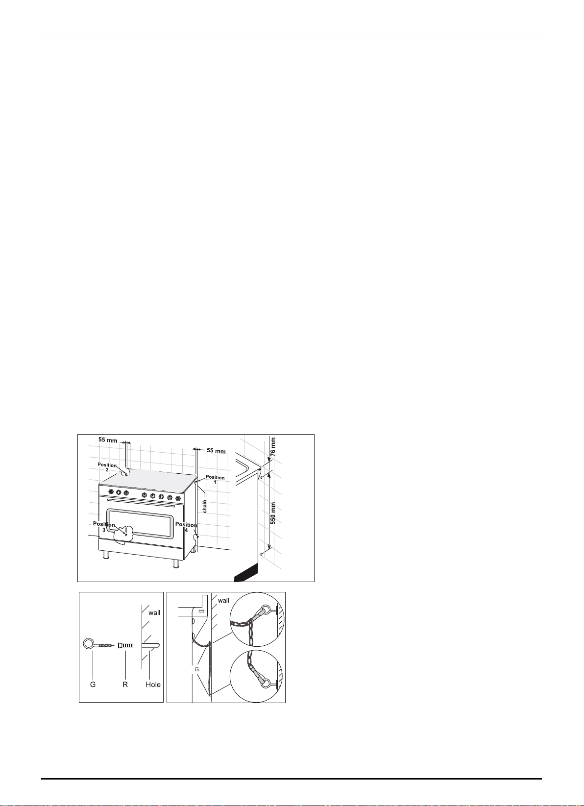
WARNING:
For safety reasons and to prevent tipping of the appliance, these stabilizing
means must
be installed. The cooker is equipped with 2 chains fixed on each side
at the rear of the cooker near the top (see Fig. A). The chains are fitted with "spring
clips" which must be clipped to the "screw eyes" provided with the cooker.
Install the "screw eyes" as follows:
Drill four 6mm holes (position 1 - 2 - 3 - 4) in the wall as in Fig. A.
Insert part "R" into the holes then screw in the "screw eyes" part "G" see Fig. B.
Note: If the part provided is not suitable for the wall material please use an
appropriate device to ensure secure holding of the "screw eyes" to the wall.
Bring the cooker near the wall and clip the chains on the "screw eyes" as in Fig. C.
IMPORTANT: If the cooker is moved for any reason (e.g. maintenance) resulting in
the cooker being unclipped from the wall, the cooker must be re-clipped to the
wall at the completion of the task.
A chain should be fitted by the installer within 50mm of the hose connection point
to prevent strain on the hose when the cooker is pulled forward. The chain should
restrict the appliance movement to no more than 80% of the hose length. After the
chain is installed, check that there is no strain on the hose or gas connections when
the cooker is pulled as far forward as the chain allows.
ONLINE: TRINITYAPPLIANCES.COM.AU
Fig. A
Fig. B Fig. C
P a g e |
10
Wall Fixing
3.7
STABILITY BRACKET
WARNING:
In order to prevent accidental tipping of the appliance, for example a child
climbing onto the open
oven door, the bracket must be installed.
Note:
If the wall plug provided is not suitable for the wall material please use an
appropriate device to ensure secure holding of the "screw" to the wall.
3.8 GAS CONNECTION
Gas installation must be made in accordance with AS5601;Also refer to range hood
manufacturers recommendation. Check gas pressure, note the correct setting from
the data plate sealed inside the front appliance drawer *.
Installing the gas cooker as follows:
(Flexible connection are NOT supplied with this appliance)
ONLINE: TRINITYAPPLIANCES.COM.AU
P a g e |
11
An inlet manifold extension pipe must be fitted to the appliance. Part supplied in
the drawer of the appliance.
Ensure that the pipe is connected using the washer provided and that the bracket
is screwed to the appliance as shown in the diagram below.
Fit the supplied pressure regulator (for Natural gas) using the NG test point adaptor
and washer to the inlet manifold. Ensure the arrow is pointing towards the
appliance and that pressure test point is accessible from the final position.
Push the cooker back and install the stabilizing chains.
Connect the appliance inlet manifold to the consumer piping outlet using only fixed
piping. This final connection is made when the product is pushed back into position
by access under the cooker.
3.9 THE HOSE ASSEMBLY
must comply with AS/NZS 1869 Class B or D,
be of appropriate internal diameter 10mm and be kept as short as possible (less
than 1.2mm)
It must not be kinked
It must not be in contact with hot surfaces.
IT IS RECOMMENDED THAT A SERVICE TAP AND UNION BE FITTED ADJACENT TO THE
APPLIANCE INLET TO FACILITATE FUTURE SERVICING.
5 burner models: set the burner pressure to 1kPa for Natural Gas and 2.75kPa for U-
LPG with the wok burner operating a full rate'. For commissioning of the appliance
with the regulator for Natural Gas, the test point pressure should be 1.00kPa with all
burners operating on HIGH.
Apply a manometer to the test nipple and reset the regulator if necessary. Do not
forget to replace the test nipple screw and to leave the instructions book with the
user.
Pressure test point for ULPG
Pressure regulator for natural
gas
Pressure test point for ULPG
A test point fitting must be installed between the piping and the appliance for the
pressure to be checked to ensure it is operating for ULPG at 2.75 kPa. Be aware that
the appliance has two gas inlets (L/R). Before performing the leakage test select
ONLINE: TRINITYAPPLIANCES.COM.AU
P a g e |
12

which side will be the connection point and cap and pressure test the side that will
not be used.
Pressure regulator for natural gas
A test point fitting must be installed between the piping and the appliance for the
pressure to be checked to ensure it is operating for NATURAL GAS at 1 kPa.
Be aware that the appliance has two gas inlets (L/R). Before performing the
leakage test select which side will be the connection point and cap and pressure
test the side that will not be used.
3.10 VERY IMPORTANT FOR THE INSTALLER
Do not attempt to turn or stress threaded elbow of the manifold: you risk damage
to this part of the gas appliance which may void the manufacturers warranty.
Before Leaving – Check all connections for gas leaks.
DO NOT use a naked flame for detecting leaks. Ignite all burners to ensure correct
operation of gas valves, burners and ignition. Turn gas taps to low flame position
and observe stability of the flame.
When satisfied with the cooker, please instruct the user on the correct method of
operation.
In case the appliance fails to operate correctly after all checks have been carried
out, refer to the authorised service provider in your area.
3.11
GAS CONVERSION AND ADJUSTMENT
When used with natural gas all burners have been preset at our factory and further
adjustment should not be necessary. Conversion kits to other gases are available
from the place of purchase. Do not attempt to fit the conversion kit yourself.
Conversion to U-LPG gas should only be carried out by an authorized technician.
3.12 GAS ADJUSTEMENTS
change the injectors
adjust the minimum flow
When conver ting from Natural Gas to U-LPG ensure that the NG regulator is
removed and replaced with the Test Point Assembly. A gas regulator suitable for a
supply pressure of 2.75kPa should be part of the gas tank supply and should be
adjusted with the wok burner operating at maximum.
ONLINE: TRINITYAPPLIANCES.COM.AU
P a g e |
13
3.13
REPLACEMENT OF THE INJECTORS
When required to operate on other gas replace the injectors in accordance with
information referred to in chart below.
Tab.1
Adjustments, conversions and gas installations must only be carried out by an
authorised person.
After there placement of the injectors, replace also the label of the type of gas.
3.14 SPECIAL NOTE
After installation or any servicing operation, always ensure that the appliance is gas
sound and that the components are now operating correctly. Items removed
during servicing should be replaced in the reverse order to their removal.
In order to change the work-top injectors, it is necessary to act as follows:
remove the grids
remove burners and flame-spreaders.
change the injector (see Fig. D) and replace it with another one suitable for the
new type of gas (see tab. 1)
Gas
Type
kPa
Jet mm ø
Burners
Power
MJ/h
Natural
1.00
1.20
Semi-quick
7.1
0.90
Auxiliary
4.0
1.50
Quick
11.0
1.63
Triple Crown
12.7
U-LPG
2.75
0.73
Semi-quick
7.1
0.53
Auxiliary
3.7
0.95
Quick
11.7
1.00
Triple Crown
13.0
Regulator
NG Regulator
LP Test point adaptor
ONLINE: TRINITYAPPLIANCES.COM.AU
Fig.D
P a g e |
14
3.15
MINIMUM FLOW ADJUSTMENT FOR HOB-TOPTAPS
In order to adjust the minimum flame setting proceed as follows: switch the burner
on, and set the knob at the minimum position . Remove the knob from the tap.
The minimum adjusting screw «Z» is on the body of the gas tap (fig. 2).
Unscrew the adjusting screw in order to increase the flow or screw it to decrease
the flow.
The correct adjustment is obtained when the flame has a length of about 3 or 4 mm.
For butane/propane gas, the adjusting screw must be screwed in tight.
Make sure that the flame does not go out turning quickly from the max. flow to
the minimum flow .
Refit the knob again.
3.16
ELECTRICAL CONNECTION
The appliance must be installed by a suitably qualified person in accordance with
these instructions and with the requirements of the Australian Wiring Rules AS/NZS
3000. Fixed wired installations are to be provided with suitable isolation means in
accordance with the said rules.
Any plug socket installed for the purpose of connecting the appliance to supply
must be readily accessible when the appliance is installed.
Before making the connection, make sure that:
the safety circuit-breaker and the electrical system are able to withstand the load
of the appliance(see nameplate).
the power supply system has an earth connection in good working order in
accordance with the regulations in force.
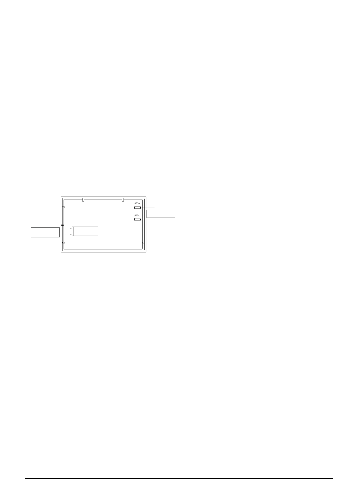
3.17 IMPORTANT INFO FOR ELECTRICAL PART
The wires in the mains lead are coloured in accordance with the following code:
GREEN &YELLOW
...........................................
EARTH
BLUE
..............................................................
NEUTRAL
BROWN
.................................................................
LIVE
Electric power 1,5 mm2 core cable (15 amp. Fuse required) Should conform to local
authority requirements.
ONLINE: TRINITYAPPLIANCES.COM.AU
Fig.2
P a g e |
15
Also refer to rangehood manufacturers recommendations. This appliance is
supplied with a plug & cord, simply plug into a 3 pin household socket outlet witch is
properly earthed.
If the supply cord is damaged, it must be replaced by an authorised service agent.
WARNING:
THIS APPLIANCE MUST BE EARTHED.
The flexible mains lead and plug must not be in contact with hot surfaces.
4 USING INSTRUCTION
4.1
WARNING:
Children should be kept away while the oven or grill is in use since accessible parts
become hot.
During use, the appliance becomes hot.
Care should be taken to avoid touching heating elements inside the oven.
Do not use oven base panel as a shelf, make use of the oven shelves.
To avoid splattering and smoke, position collecting tray under the grill with some
water in it.
Always turn pan handles to the side or to the back of the hob. If they are left out
into the room they can easily be hit or reached by children, knocking the pan off
the hob.
Don’t let children sit down or play with the oven door. Do not use the drop down
door as a stool to reach above cabinets.
Once your cooking is over make sure to close the main gas supply.
ONLINE: TRINITYAPPLIANCES.COM.AU
P a g e |
16
4.2
- 1 MINUTE TOUR -
Be safe
Please read the rest of the instruction book which contains important information
to help you use the appliance safely and efficiently.
Gas and Electricity on
Make sure that the gas supply is turned on and that the appliance is plugged in
and switched on. The ignitor needs electricity.
In case there is no electric current, the burner can also be lit using a match.
It is recommended that pans suitable to the size of the burner should be used as
follows:
BURNERS
PANS
min.
max.
AUXILIARY
80 mm
160 mm
SEMI-RAPID
120 mm
200 mm
RAPIDE
200 mm
230 mm
TRIPLE CROWN
230 mm
260 mm
Always use pans with a flat base diameter, which are well balanced and stable
in use, a pan which overhangs the hotplate should not be used. Avoid using old,
misshapen pans, or pans which are unstable when placed on a flat surface. Do not
use “split pans” as they are inherently unstable. To save gas, always position pans
centrally over the burners and adjust the flames so that they do not lick up the sides
of the pan and only the base is heated. Always put lids on saucepans and boil only
the amount of liquid you need. When the liquid has boiled adjust the setting to
maintain a simmer. Do not light the burner until the pan is in position and turn off the
burner before removing the pan. In hard water areas, descale kettles regularly. For
safety, keep saucepan handles turned to a safe position so they are out of reach
of small children and cannot be accidentally knocked.
To the burner OFF, turn the control knob clockwise to the OFF setting (marked with a
dot
The small flame indicates the ‘low position’.
Turn the knob to it after the contents of a pan have boiled.
ONLINE: TRINITYAPPLIANCES.COM.AU
.)
P a g e |
17

The smaller burners are for smaller pans and simmering. Make sure flames are under
the pans. Using a lid will help the contents boil more quickly.
WARNING:
It is not recommended to press push button for ignition if all the burners are not
located in the proper positions. The burner heads, burner skirts and pan supports are
removable for better cleaning: Always ensure that the burner skirts and heads are
replaced correctly so that the burners function safely and correctly.
During the use of the appliance pay attention that water or any liquid does not
enter into the appliance through the holes of the burners or around the rods of the
valves or the push button electronic lighter.
Water or juice will produce dangerous short-circuits and can seriously damage the
working of the Hotplate.
4.3
HOW TO USE YOUR ELECTRIC OVEN
Before cooking in the first time we reccommend that the oven should be operated
at 200° C for 30 minutes to remove any manufacturing greases and odours.
Do not place items or pan directly on to the oven botton.
Foil should only be used to cover food and not oven shelves or part of the oven.
When used improperly will obstruct the air circulation causing problems in cooking
and/or harmful accidents.
4.4
MULTIFUNCTION OVEN
The oven is fitted with:
a lower heating element;
an upper heating element;
a circular heating element surrounding the fan.
N.B.: Always set the temperature on the thermostat knob before selecting any of
the functions.
Oven thermostat knob
ONLINE: TRINITYAPPLIANCES.COM.AU
P a g e |
18
To obtain an oven temperature between 50 ° C and MAX ° C, turn the knob
clockwise.
Oven function knob
Depending on the type of oven, it is possible to select one of the following
functions turning the knob clockwise.
Note:
All the functions mentioned above switch the oven internal light on. A warning
light on the control panel will stay lit until the temperature is reached; after it will
light up intermittently. Always use the oven with the oven door closed.
Use of the oven
Note: ovens with separate thermostat and commutator. When the functions Grill
and Fun Grill are used, place the thermostat knob between 180 ÷ 200 ° C as
maximum tempera- ture.
ATTENTION:
The temperature shown on the control panel corresponds to the temperature in
the oven centre only when the functions selected are Bake or Fan Oven.
ONLINE: TRINITYAPPLIANCES.COM.AU
Grill
Medium Grill
Fan Bake
Fan grill
Bake
Defrost
Lower
Light
Fan
P a g e |
19

Light
When you turn the control knob to this position, the light will be on for all the
following operations.
Defrost
The air at ambient temperature is distributed inside the oven for defrosting food
very quickly.
Conventional cooking
Top and bottom heating elements are used together. Preheat the oven for about
ten minutes.
This method is ideal for all traditional roasting and baking. For sealing red meats,
roast beef, leg of lamb game, bread, foil-wrapped food and flaky pastry. Mid
shelf position is recommended.
Cooking of similar or different foods placed on different shelves (up to 2 levels at a
time).
Fan cooking
Both top and bottom heating elements are used and the fan circulates the air
inside the oven. Recommended for poultry, pastries, fish and vegetables. Heat
penetrates the food better and both the cooking and preheating times are
reduced. Different foods can be cooked at the same time in one or more positions.
This function provides even heat distribution. Allow about ten minutes extra when
cooking foods or more dishes at the same time.
Lower element
Using the lower element. Ideal for cooking all pastry based dishes. This allows you
to cook dry pastry without over cooking the filling. Use this for flans, quiches, tarts,
pâté and any cooking that needs more heat and radiation from below.
Grill
Caution: In this function the temperature control knob must be set from 50°C to
Grill position. Using the top level element. Five minutes preheating is required to get
the element hot. Keep the door closed when using the grill.
ONLINE: TRINITYAPPLIANCES.COM.AU
P a g e |
20
Fan assist multilevel oven
Fan assist multilevel oven

Fan assisted grilling
Caution: In this function the temperature control knob must be set from 50°C to
Gril position. The top heating element is used in conjunction with the fan circulating
the air inside the oven. Ideal for cooking thick food stuffs, whole pieces of meat
such as roast pork, poultry, etc. Preheating is necesary for red meats but not for
white meats. Place the food to be grilled directly on the shelf centrally, at the
middle level. Slide the driptray under the shelf to collect the juices. Make sure that
the food is not too close to the grill. Turn the food over halfway through cooking.
Rotisserie (for some models only)
The top heating element is used in conjunction with the rotisserie providing the real
flavour of a traditional roast.
4.5 GENERAL INSTRUCTION
Warning: remember ovens get hot; some parts naturally become very hot, notably
the glass oven door and the protective strip. Keep children away from oven at all
times and warn them about the danger.
4.6 GUIDE FOR CONVENTIONAL COOKING (BAKE)
(Outer ring of upper electric element and lower electric element ON) The following
Cooking Guides give the recommended shelf positions (counted from the bottom),
thermostat settings and approximate cooking times for a range of baked items,
using the conventional oven, using one tray only. Cooking results are a matter of
personal preference and may easily be adjusted to suit individual requirements by
slight adjustment of the temperature and or cooking time.
Preheating of the oven is recommended for 10-15 minutes or until the oven
thermostat indicator light switches off to show the selected temperature has been
reached.
ONLINE: TRINITYAPPLIANCES.COM.AU
P a g e |
21

When using a baking tray it should be placed centrally on the oven shelf with the
short sides of the tray parallel to the sides of the oven. Do not use trays, tins or dishes
larger than 380 mm (15") long, 356 mm (14") wide, as cooking results may be
impaired.
Food
Thermostat
setting °C
Shelf Position
(Counted from Bottom)
Cooking Time
Small cakes
(12 on tray)
195 °C
3
20 - 30 mins.
Victoria sandwich
(2x7"/180mm)
190 °C
3
25 - 35 mins.
Swiss roll or whisked
sponge
200 °C
3
20 - 25 mins.
Fruit cake
(8"/205mm)
155 °C
2
2 - 3 hours.
Scones
260 °C
3
10 - 20 mins.
Meringues
95 °C
2
2 - 3 hours.
Shortcrust Pastry
210 °C
3
25 - 45 mins. depending
Puff or Flaky Pastry
220 °C
2
20 - 35 mins. upon
Choux Pastry
220 °C
3
25 - 35 mins. dish
Biscuits
200/220 °C
3
15 - 25 mins.
depending upon type
Bread
250 °C
2
30 - 40 mins.
Milk pudding
Pizza
165 °C
270 °C
2
3
1 H - 2 hours.
25 mins.
Lasagne
170 °C
3
75 mins.
Oven noodles
160 °C
3
75 mins.
BEEF on bone &
crusty (rare)
(medium)
(well done)
270 rare
220 °C
220 °C
180 °C
3
3
3
3
12 mins. per 1/b (500 g) plus 12 mins.
15 mins. per 1/b (500 g) plus 15 mins.
20 mins. per 1/b (500 g) plus 20 mins.
25 mins. per 1/b (500 g) plus 15 mins.
LAMB on bone
220 °C
170 °C
3
3
20 mins. per 1/b (500 g) plus 20 mins.
27 mins. per 1/b (500 g) plus 27 mins.
Boned and rolled
220 °C
170 °C
3
3
25 mins. per 1/b (500 g) plus 25 mins.
35 mins. per 1/b (500 g) plus 20 mins.
PORK on bone
220 °C
3
25 mins. per 1/b (500 g) plus 25 mins.
Boned and roller
180 °C
3
30-35 mins. per 1/b (500 g) plus 35 mins.
VEAL on bone
220 °C
3
25 mins. per 1/b (500 g) plus 25 mins.
Boned and roller
220 °C
3
30 mins. per 1/b (500 g) plus 30 mins.
CHICKEN
220 °C
170 °C
3
3
20 mins. per 1/b (500 g) plus 20 mins.
25 mins. per 1/b (500 g) plus 25 mins.
TURKEY
220 °C
170 °C
3
3
20 mins. per 1/b (500 g)
25 mins. per 1/b (500 g)
DUCK
220 °C
170 °C
3
3
20 mins. per 1/b (500 g)
25 mins. per 1/b (500 g)
GOOSE
220 °C
3
20 mins. per 1/b (500 g) plus 20
ONLINE: TRINITYAPPLIANCES.COM.AU
P a g e |
22

4.7 PLATE WARMING
Ovenproof plates and dishes may be warmed in the oven on a low temperature
setting. Remember do not place items directly onto the oven base.
Warning: do not use foil to cover the oven shelves, or any part of the oven interior
including the oven base. Foil should only be used to cover food and cooking dishes.
Always place items which may boil over (e.g. fruit pies) on a baking tray to prevent
spillage burning onto the oven base. Foil used improperly is frequent cause of oven
problems and painful accidents. Avoid letting grease deposit collect around the
upper heating element: it will cause smoking and may start a fire.Remember do not
place pan or items directly onto the oven base. Never leave unit unattended at
high heat settings. Boil over causes smoking and greasy spill over that may start a
fire. If a grease fire should occur in a pan put out the flame by placing a lid on the
pan. Never throw water on a grease fire. Close the door and turn off the gas supply.
4.8 GUIDE FOR FORCED CONVECTION COOKING
(Back rolled electric element with fan)
The accessories provided with the oven can be slotted in at 5 positions: the
following guide concerns cooking times and thermostat settings using N. 2 shelves
on the same time (in position N. 2 and N. 4). Cooked results are a matter of personal
preference and may easily be adjusted to suit individual requirements by slight
adjustment of the tempera- ture and/or cooking time, or when using more or less
shelves in the same time. Preheating of the oven is recommended for 10-15 minutes
or until the oven thermostat indicator light switches off to show the selected
temperature has been reached.
When using a baking tray it should be placed centrally on the oven shelf with the
short sides of the tray parallel to the sides of the oven. Do not use trays, tins or dishes
larger than 380mm (15") long, 356 mm (14") wide, as cooking results may be
impaired.
ONLINE: TRINITYAPPLIANCES.COM.AU
P a g e |
23

4.9 USING THE GRILL
The grill is situated in the top of the oven compartment.
The grill pan should be located on the top oven shelf position. Always grill with the
door closed.
Food
Thermostat setting °C
Cooking Time
Small cakes (12 on tray)
175
15-25 mins.
Victoria sandwich
(2x7"/180mm)
170
20-30 mins.
Swiss roll or whisked
sponge
180
15-20 mins.
Fruit cake (8"/205mm)
135
1 H - 2 H hours.
Scones
210
8-15 mins.
Meringues
80
1 H - 2 H hours.
Shortcrust Pastry
190
20-40 mins. depending
Puff or Flaky Pastry
200
15-30 mins. upon
Choux Pastry
200
20-30 mins. dish
Biscuits
170/180
10-20 mins. depending upon type
Bread
200/220
25-35 mins.
Milk pudding
150
1 H - 2 hours.
Pizza
250
20 mins.
Lasagne
165
60 mins.
Oven noodles
150
60 mins.
BEEF on bone
230 rare & crusty
9 mins. per 1/b (500 g) plus 9 mins.
BEEF on bone
190 °C (rare)
15 mins. per 1/b (500 g) plus 8 mins.
190 °C (medium)
20 mins.per 1/b (500 g) plus 10 mins.
160 °C (well done)
25 mins. per 1/b (500 g) plus 8 mins.
Boned and rolled
190 °C (rare)
20 mins.per 1/b (500 g) plus 10 mins.
190 °C (medium)
25 mins. per 1/b (500 g) plus 15 mins.
160 °C (well done)
30 mins. per 1/b (500 g) plus 8 mins.
LAMB on bone
190 °C
20 mins.per 1/b (500 g) plus 10 mins.
155 °C
27 mins. per 1/b (500 g) plus 14 mins.
Boned and rolled
190 °C
25 mins.per 1/b (500 g) plus 14 mins.
155 °C
25 mins.per 1/b (500 g) plus 14 mins.
PORK on bone
200 °C
25 mins.per 1/b (500 g) plus 14 mins.
Boned and roller
160 °C
30-35 mins. per 1/b (500 g) plus 18 mins.
VEAL on bone
200 °C
25 mins.per 1/b (500 g) plus 14 mins.
Boned and roller
200 °C
30 mins.per 1/b (500 g) plus 14 mins.
CHICKEN
200 °C
20 mins.per 1/b (500 g) plus 10 mins.
155 °C
25 mins.per 1/b (500 g) plus 13 mins.
TURKEY
200 °C
18 mins.per 1/b (500 g) plus 14 mins.
155 °C
23 mins. per 1/b (500 g)
DUCK
200 °C
18 mins. per 1/b (500 g)
155 °C
23 mins. per 1/b (500 g)
GOOSE
180 °C
18 mins.per 1/b (500 g) plus 20 mins.
ONLINE: TRINITYAPPLIANCES.COM.AU
P a g e |
24
Warning:
Do not place fatty foods too close to the grill and never leave the grill unattended.
If fatty foods are grilled, or roast has been cooked in the oven at a high
temperature the grill element may smoke. This is not dangerous and the smoke is
caused by the fat burning off when the grill element is hot. Leave the grill element
on until the smoking has stopped then use as normal. If a grease fire should occur
in a pan put out the flame by placing a lid on the pan. Never throw water on a
grease fire.
4.10 INSTRUCTION FOR USE OF CONTROL DEVICES
(Depending on model)
Using the Cooking Programs
Main functions (for some models):
Time function, in 24 hours format.
Make a reservation for the oven work time, and can set anytime in 24 hours.
Set the oven work time, the longest upto10 hours.
4.11 OPERATION PANEL AND INSTRUCTIONS
(for some models)
List of functions
Instructions from left to right:
Key1, Key2, Key3.
Key1 Decrease Key
Key2 Mode Key
Key3 Increase Key
Note: Press Key 1 and Key 3 under the setting mode, which nchanges the time by
one minute either up or down. If keep pressing them, the number will be up or down
quickly.
ONLINE: TRINITYAPPLIANCES.COM.AU
TIME-SETTING
RELAY OPERATION ICON
NUMBER DISPLAY
ICON
P a g e |
25
AUTO -PROGRAMMING
ICON
EC ICONS
ALARM ICON
on-off control
Power source
Icon Instructions
“Auto-programming icon” : it will flash when setting automatic program and the
end of automatic program. If automatic program has been set, after 5s, it will keep
lighting up. At the end of automatic program, the flash will be off when resetting
the clock or it will keep lighting up when resetting automatic program after 5s.
“Time-setting Icon” will flash when setting time.
“Sec Icon” and “Alarm Icon” are flashing under the mode of time setting and
alarm setting, after 5s of setting, it will turn to lighting up.
“ Relay Operation Icon ” b shows the working state of relays. The icon will keep
lighting up if contact are connected, and will be off if contacts are disconnected.
“Number Display” is LED Nixie Tube.
4.12 CONTROL FUNCTION AND INSTRUCTIONS
As shown in the picture, on-off control is used to control heating components of
oven, the left is power source which can be connected under the 220V.
Time Adjustment after Starting up
When the power is on, it shows 12:00 and flashes. The relay contact is
disconnected, auto-programming icon keeps lighting up, time setting icon flashes.
Press K1 or K3 to the time or press K2 to get into the present working mode. The
relay contact is connected.
Press K2 by 4 times to get into the present time-setting mode under the common
mode.
Alarm and Buzz Function
Press K2 once under the common mode: "Alarm Icon" flashes.”
Press K1 or K3 to adjust the present alarm clock.
5s after adjusting to the time you need, "Alarm Icon" keeps flashing, and will work
after setting up. In this case, pressing K1 can know the alarming time( it will show
seconds at one ast minute).
When alarm counts down to zero, alarming program ends, alarm icon flashes, and
the buzzer os buzzing. Press any key to stop the buzzing or it will turn off
automatically after 2 minutes.
ONLINE: TRINITYAPPLIANCES.COM.AU
P a g e |
26

Auto-programming Setting and Instructions
Semi automatic program mode
Use this setting for oven working time, automatic heating switch-off at the end of
setting time, buzzer will inform the user.
Press K2 twice or three times to get into the auto-program- ming time setting,
“Auto-programming Icon” flashes. Press K1 and K3 to aujust continuous time and
end time.
5s after setting, it will work automatically, "Auto-program- ming Icon" keeps lighting
up. If continuous time is 0, turn off the relay contact, and "Relay Operation Icon" is
dark, "Auto programming Icon" flashes, the buzzer is buzzing.
This mode ’ s range of continuous time and end time: Adjustment range for
continuous time: >0 but <10 hours Adjustment range for end time: present time <
end time < = present time + 10 hours.
If meet this standard: end time = present time + continuous time.
For example: the present time is 2: 00, then the max. end time is adjusted to 12:00
(2: 00 10 00 12 00). When the end time is adjusted to 12:00, then the continuous
time is 10:00.
5s after adjusted, automatic program is working. After 10 hours, if continuous time is
counting down to 0, turn off the relay contact, and “ Relay Operation Icon” is
dark, “Auto-programming Icon” flashes, the buzzer is buzzing.
Note:
only use this setting for either continuous time or end time. For example: the
present time is 2:00, and if let the oven work for 3 hours, set the continuous time to
3:00, and the end time will automatically change to 5:00 and vice versa.
If the continuous time is equal to 0 or the end time is equal to the present time, it
means that the automatic program is over.
When the automatic program is over, the continuous time is 0 and the end time is
equal to the present time.
Automatic Mode
Use this mode for setting oven’s starting time and end time, which means make
an appointment to boot. When the time isover, it will automatically turn off the
heating and the buzzer is buzzing to inform the user.
Press twice to get into the continuous time setting mode under the common mode,
press three times to get into the end time.
When the continuous time setting is ok or the end time setting is ok, then press K2 to
get into the other kind of automatic program time setting, "Auto-programming
ONLINE: TRINITYAPPLIANCES.COM.AU
P a g e |
27

Icon" flashes, press K1 and K3 to ad just continuous time and end time setting
mode.
5s after automatic program setting, it will automatically work, and "Auto-
programming Icon" keeps lighting up. Turn off the relay conntact, and the icon i s
dark. When work until the starting time, the relay contact is connected, the icon is
light. When the continuous time is counting down, if the continuous time is 0,turn off
the relay contact, "Relay Operation Icon" is dark, "Auto-programming Icon" flashes,
and the buzzer is buzzing.
The continuous time and the end time under this model will be set as follow:
Starting time = end time - continuous time
For example, the present time is 2:00, set the continuous time to 3:00, and the end
time to 10:00, then the starting time is 7:00 (7:00 10:00 3:00). The relay contact is
connected and its icon is light. After working for continuous 3 hours, the continuous
time is 0, turn off the relay contact, "Relay Operation Icon" is dark, “ Auto-
programming Icon” flashes, the buzzer is buzzing.
Note:
End time > present time + continuous time,< but 23 hours and 59 minutes
For example: the present time is 2:00, continuous time is 0:01, then the range for
end time is 2:02 (2:02 2:00+1).
Continuous time > 1 minute, continuous time and end time both will be set.
If the continuous time is equal to 0 or the end time is equal to the present time it
meas the automatic program is over.
When the automatic program is over, the continuous time is 0, and the end time is
the same with the present time.
Cancel Function
When semiautomatic or automatic function is starting, press K1 and K3 at the same
time which can cancel the automatic mode. (to cancel continuous time and end
time).
4.13
CONTROL KNOB FOR MINUTE MINDER
(for some models)
ONLINE: TRINITYAPPLIANCES.COM.AU
P a g e |
28
The minute minder is a countdown timer which emits an audible signal when the
cooking time has elapsed.
The minute minder runs independently of the oven.
Use this control knob to set the cooking time.
SETTING MEANING
OFF
1-50 Cooking time in minutes
4.14
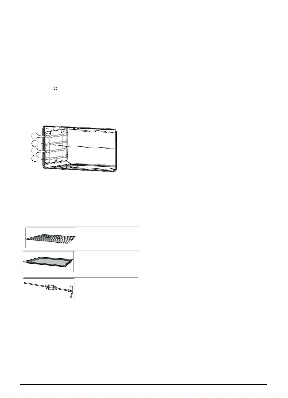
ACCESSORIES
The accessories can be inserted in the oven in 4 different shelf positions.
You can pull the accessories two-thirds of the way out without them tipping. This
allows dishes to be removed easily.
You can buy accessories from the after-sales service or from specialist retailers.
ACCESSORY DESCRIPTION
Baking and roasting shelf
For ovenware, cake tins,
roasts, grilling and frozen
meals.
Enamelled baking tray
For moist cakes, pastries, frozen meals and large roasts. Can also be inserted
underneath the wire rack or rotary spit and used as a drip tray to collect fat.
Rotisserie (option)
For roasts and large pieces of poultry. Use only in combination with the
enamelled baking tray.
4.15 USE OF THE ELECTRIC GRILL
USING THE GRILL
Turn the oven knob to the right and place it on the grill position. The grill pan should
be located on the top oven shelf position. Always preheat the grill on full for 3-5
minutes before inserting the food.
The user can change the shelves, depending on his personal whishes and on the
different food.
ONLINE: TRINITYAPPLIANCES.COM.AU
1
2
3
4
P a g e |
29
To remove the shelves from the oven, pull them forward you, tilt front end upward
and pull them out.
To replace it in the reverse of above.
Install shelves by locating them in the horizontal guide rails on the oven walls. The
raised portion of the shelf is to be facing the rear wall of the oven.
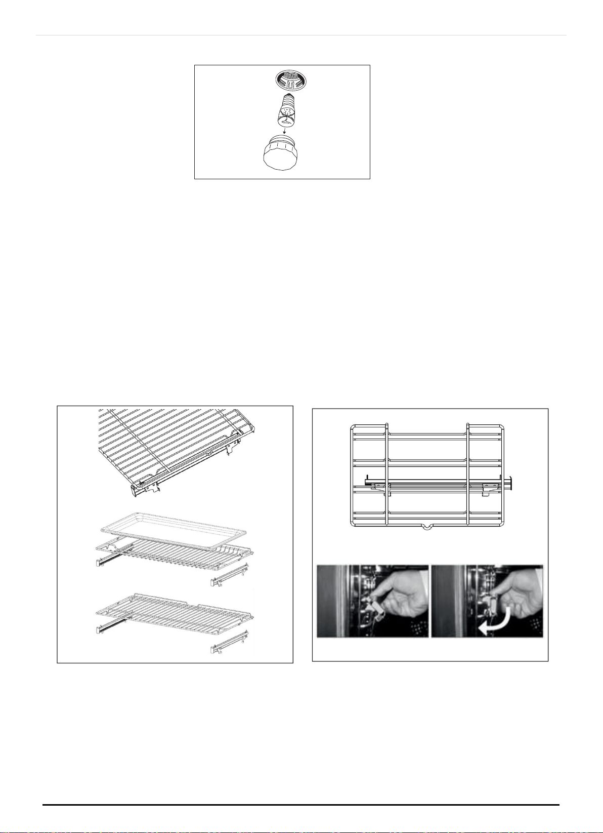
4.16 USING THE ROTISSERIE
(special for models with rotisseries)
The rotisserie spit can be used to cook joints such as rolled joints and poultry with
excellent results. The meat is roasted thoroughly and evenly.
Use the rotisserie spit in conjunction with the grill.
Preparing joints
Place the joint as centrally as possible on the rotisserie spit and secure it at both
ends with the retaining clips.
You can also truss the joint with string. With poultry, bind the ends of the wings
underneath the back and the thighs against the body. This will prevent them from
becoming too dark.
Pierce the skin on the underside of the wings to allow the fat to escape.
4.17
INSERTING THE ROTISSERIE
(special for models with rotisseries)
Insert the rotary spit as follows:
Hook the rotisserie into the bracket on the ceiling of the cooking compartment.
If you require to preheat the oven, hook in the holder before preheating.
Risk of burns
Never touch the hot surfaces of the cooking compartment or the heating
elements.
Children must be kept at a safe distance from the applian- ce at all times.
Open the appliance door carefully. Hot steam may escape.
ONLINE: TRINITYAPPLIANCES.COM.AU
Bump
P a g e |
30
If the oven has been preheated, only attach the rotary spit if you are using an
oven cloth or wearing (thermal) oven gloves. To attach the spit, slide one end into
the recessed adapter in the left-hand side panel of the cooking compartment.
Hook the other end into the holder.
Pour a little bit of water into the baking tray and slide this into shelf position 1 to
collect the run-off fat.
4.18 REMOVING THE ROTARY SPIT
(special for models with rotisseries)
Risk of burns.
Never touch the hot surfaces of the cooking compart- ment or the heating
elements.
Children must be kept at a safe distance from the appliance at all times.
Open the appliance door carefully. Hot steam may escape.
Risk of burns.
Never touch the rotary spit or other accessories directly when they are hot.
Always wear oven gloves or heat-resistant gloves when handling hot accessories.
Remove the rotary spit as follows:
Carefully open the appliance door. Carefully remove the rotary spit from the
holder.
ONLINE: TRINITYAPPLIANCES.COM.AU
P a g e |
31
Carefully withdraw the rotary spit from the recessed adapter in the side panel and
remove it rom the oven.
Take out the baking tray.
5 CLEANING
5.1 NOTE
Before cleaning the appliance, close the gas stopcock and unplug appliance or
disconnect power at the main circuit breaker of the electrical system.
Do not clean the appliance surfaces when still hot.
Always clean off spillage as quickly as possible to prevent burning on which will
make removal more difficult. Wash with a clean cloth soaked in hot soapy water,
rinse and dry with a soft cloth.
DO NOT USE ABRASIVES. CAUSTIC PASTES OR SPRAYS. COARSE CLEANING PADS OR
POWDERS. DO NOT USE EXCESSIVE WATER WHEN CLEANING YOUR OVEN IN ORDER
TO AVOID WATER PRESSING THROUGH CLEFTS INTO THE BACK OF CONTROLS PANEL
OR OF THE UNIT.
A steam cleaner is not to be used for cleaning this appliance.
5.2 PAN SUPPORTS AND BURNERS
The burner heads can be removed for cleaning. NB Do not drop hot burner caps in
cold water.
Because of the rapid cooling they might get damaged.
Lift off and soak for about 10 minutes in hot water with a little detergent. After
having cleaned and washed them, dry them carefully.
ONLINE: TRINITYAPPLIANCES.COM.AU
P a g e |
32
C
B
A
Fig. F
B
A
Fig. E
A
B
Make sure that no burner holes are clogged.
Clean the burners once a week or more frequently if necessary.
Make sure you have reassembled the burners correctly. Pan supports can be
washed by hand or in a dishwasher. Remember to remove rubber feet (if fitted)
prior to washing. Refit them afterwards.
Do not use harsh abrasive cleaners or sharp metal scrapers to clean the oven door
glass since they can scratch the surface, which may result in shattering of the glass.
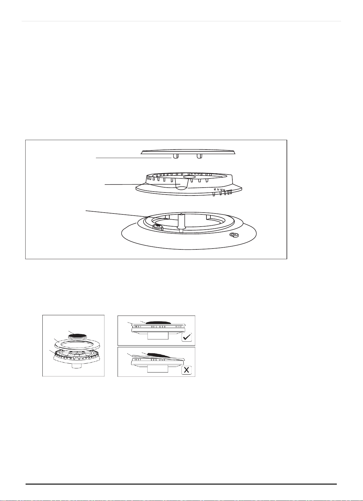
For a triple crown burner, make sure head “C” and covers “A” and “B” are
properly placed on their seats as figure E and not off-centered as in figure F
5.3 DAILY CLEANING
Regular wiping down directly after use prevents dirt from burning on. Clean the
appliance with water and a detergent or all purpose cleaner.
Avoid using too much water to prevent it entering the burner or ventilation
openings.
You can remove the hook-in racks in order to clean them separately.
ONLINE: TRINITYAPPLIANCES.COM.AU
notch for electrode
in burner head
electrode
burner cap
locating pegs
P a g e |
33
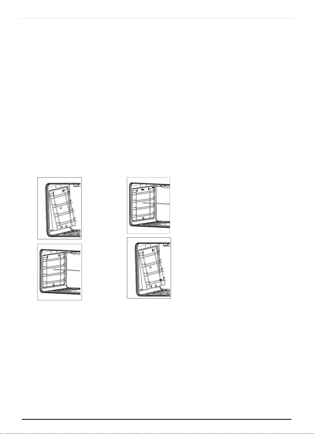
The hook-in racks are all fixed to the walls of the cooking compartment at four
points.
To remove the hook-in racks, proceed as follows: (Fig. G
Undo the screw on the bottom the hooking rack. The lower hooks of the hook-in
rack are released.
Take hold of the top of the hook-in rack and screw. On the screw on the bottom
the hook-in rack again.
To reinsert the hook-in racks, proceed as follows: (Fig. H)
Insert the upper hooks into the drill holes in the side panel.
Pull the hook-in rack slightly downwards and insert the lower hooks into the drill
holes.
Removing the hook-in racks Inserting the hook-in rack
Oven accessories (shelves, trays etc) should be washed in mild detergent solution
and should not be treated with abrasives. The oven interior panels should be
cleaned with mild detergent solution, mild cream cleaners or a moist soap pad.
lnstall shelves by locating them in the horizontal guide rails on the oven walls.
The raised portion of the shelf is to be facing the rear wall of the oven.
IMPORTANT: Do not use excessive water when cleaning the oven and avoid water
passing through the fan grill or ducts in the oven back . Avoid letting grease deposit
collect around the upper heating element: it will cause smoking and may start a fire.
ONLINE: TRINITYAPPLIANCES.COM.AU
Fig. G Fig. H
P a g e |
34
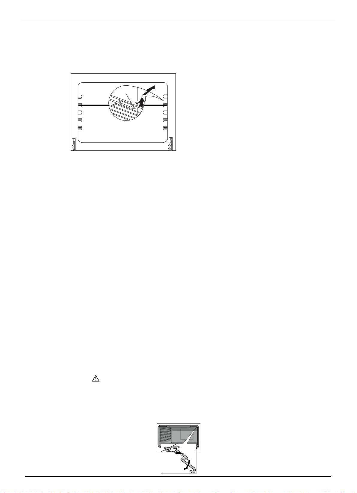
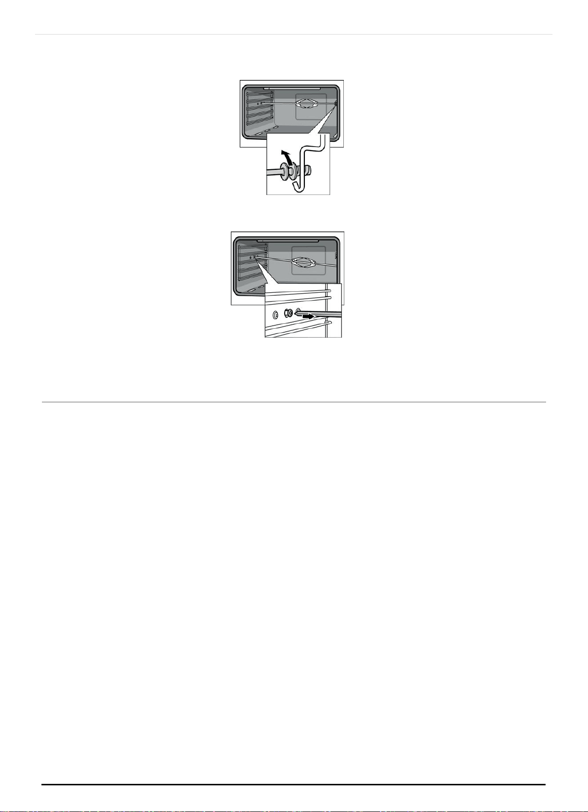
5.4 CLEANING THE INTERIOR GLASS OF THE OVEN
The interior glass of the oven door can be removed: with the door in the semi-open
position, use both hands to remove the glass.
After cleaning, refit the glass by proceeding in reverse order.
Note:
In some models, the glass is screenprinted. In this case, when refitting the glass
make sure the screenprinted part is legible when the oven door is opended.
The interior glass of the oven can be removed:
open the oven door completely.
flip the hinge hooks "A" outwards (see fig. 5B).
shut the oven door slowly until it reaches hooks "A", making sure these are locked
into slots "B" of the oven door, as shown in fig. 5C.
with the door in a semi-open position, remove the screws A and B and the profile C
as shown in fig. 4.
use both hands to remove the glass as shown in figures 4.
after cleaning, refit the glass by proceeding in reverse order.
Fig.4
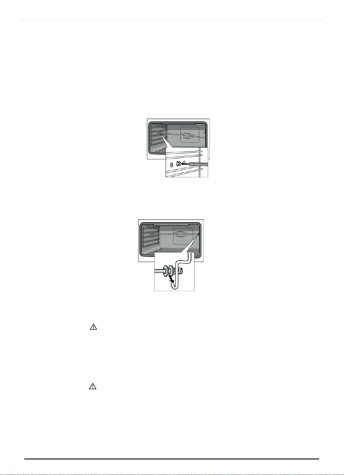
5.5 THE INNER GLASS OF THE OVEN WITH FIXING SNAP
(only for the models where is provided)
The inner glass of the oven door can be removed:
open the oven door completely.
flip the hinge hooks "A" outwards (see fig. 5B).
shut the oven door slowly until it reaches hooks "A", making sure that hinges are
locked into slots "B" of the oven door, as shown in fig. 5C.
B
A
C
ONLINE: TRINITYAPPLIANCES.COM.AU
P a g e |
35
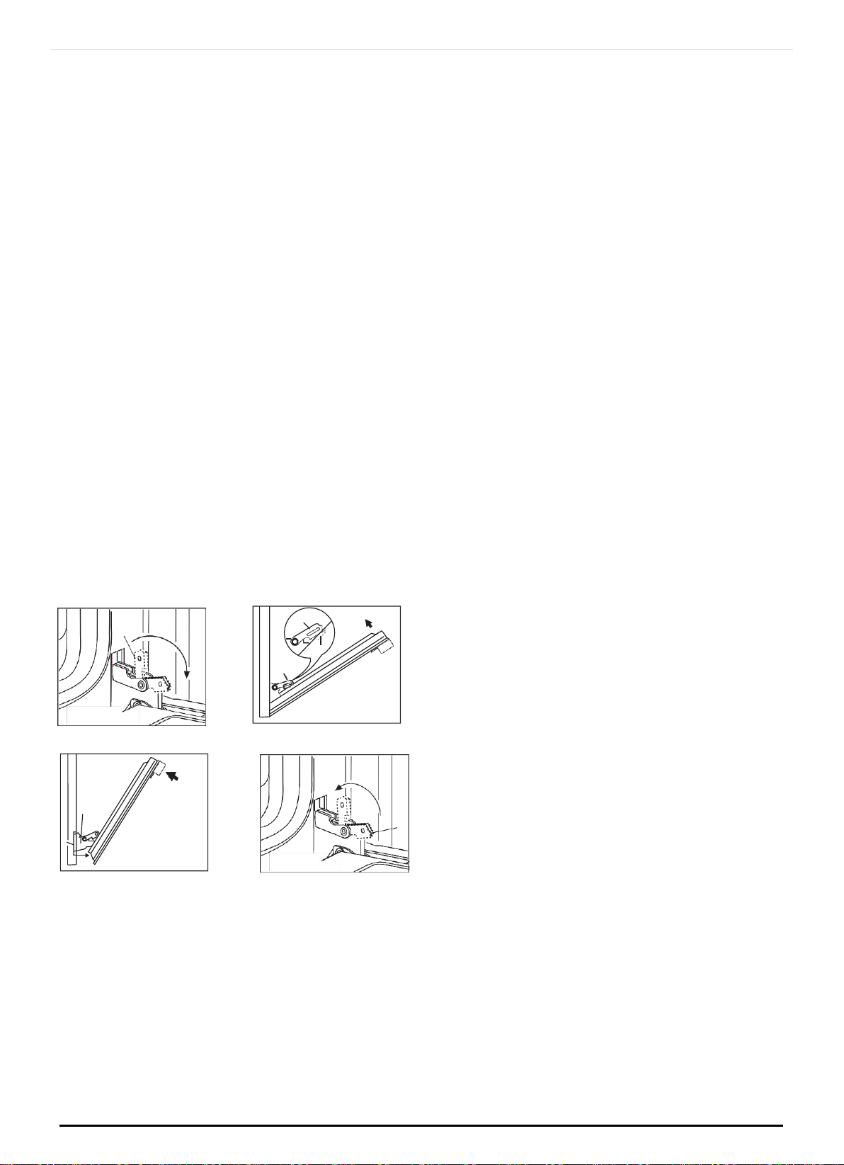
with the door in a semi-open position, press the two buttons C on the upper profile ,
and extract the profile as shown in fig. 4
use both hands to remove the glass as shown in figures 4.
after cleaning, refit the glass by proceeding in reverse order.
5.6
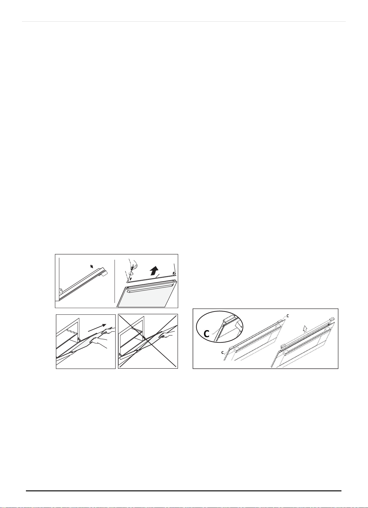
REMOVAL OF OVEN DOOR
In-depth cleaning of the oven becomes more convenient if the door is removed
following the instructions below:
open the oven door completely.
flip the hinge hooks "A" outwards (see fig. 5B).
shut the oven door slowly until it reaches hooks "A", making sure these are locked
into slots "B" of the oven door, as shown in fig. 5C. Remove the glass FIg. 5A (only for
models where present).
Using both hands, push the oven door lightly inwards, to enable the door hinges "C"
to come away from the slots "D" (see fig. 5D) and pull the door towards you until it is
released from the oven.
After cleaning it, reposition it correctly following the abovesteps in the reverse order
and flipping hooks "A" inwardsbefore you shut the oven door (fig. 5E).
C
D
Fig. 5D
A
Fig. 5E
CAUTION:Do not use rough or abrasive materials or sharp metal scrapers to clean
the glass doors of the oven since they may scratch the surface and cause the glass
to break.
WARNINGS:Before performing any repair or operation, switch the applian- ce off
and close the gas tap.
The manufacturer declines all responsibility for any damage to persons, animals or
things caused by failure to observe the rules indicated above. In case it is
necessary to repair or replace the inside components, act as follows:
Fig.5C
A
B
A
A
Fig. 5B
ONLINE: TRINITYAPPLIANCES.COM.AU
P a g e |
36
WARNINGS:Isolate the cooker from the electricity supply before attemp- ting to
replace the oven lamp.
The oven lamp used is of a special type withstanding high temperatures. To replace
it, act as follows: disassemble the protecting glass (A) and replace the burnt lamp
with one of the same type. Reassemble the protecting glass.
5.7
TELESCOPIC RAILS
(only for the models where is provided)
The oven is equipped with telescopic rails to position the pan and wire grid (Fig. 3d).
You can change the position, depending on your personal taste and needs of
different foods (Fig. 3e).
5.8 DISASSEMBLY OF WORK-TOP
Disassembly of the worktop must only be done by a qualified service technician.
In case it is necessary to repair or replace the inside compo- nents, act as follows:
Remove the grids, remove burners and flame-spreaders (see fig. 6), unscrew the
visible screws “V” placed on the work-top (see fig. 7). Disassemble the work-top by
Fig. 3D
Fig. 3E
ONLINE: TRINITYAPPLIANCES.COM.AU
P a g e |
37
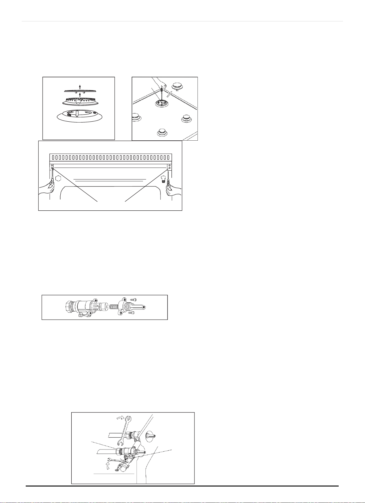
A
Fig. 8
mod.
unscrewing the rear screws “A” (see fig. 8 according to the models). In this way it is
possible to lift the work-top and to reach the inside compo- nents.
5.9 GREASING OF TAPS
If a tap becomes hard to be turned, grease it using a specific grease withstanding
high temperatures. Act as follows: open the work-top and disassemble also the
control panel as described on the previous paragraph. Unscrew the two fixing
screws from the burner body (see picture) and remove the cone.
5.10 TAP REPLACEMENT
Act as follows: open the work-top and disassemble also the control panel as
described on the previous paragraph. Unscrew screw nut D of the gas tube
supplying the burner. Unscrew screw V fixing the tap to the bridle and remove it
(see picture).
Note: Every time a tap is replaced, it is necessary to replace the seal gasket too.
Check the connection seal by means of soapy water.
Fig.6
V
Fig. 7
ONLINE: TRINITYAPPLIANCES.COM.AU
D
7
V
P a g e |
38

Clean the cone and it's slot by means of a cloth soaked with solvent. Slightly
grease the cone with the relevant grease, put it in it's slot, and turn it a few times.
Remove the cone again, remove the excess grease making sure the gas entries
are not obstructed by grease residue. Assemble everything carefully in the opposite
direction check the connection seal by means of soapy water.
6 SOME SAFETY POINTS
6.1
DO NOT USE THE APPLIANCE AS A SPACE HEATER. IF YOU SMELL GAS
Open a window. Do not use any electrical switches. Immediately extinguish naked
flames. Isolate appliance from gas mains supplies via the isolation stopcock.
Contact local gas authority or emergency services as appropriate. In the event of
food fire. Isolate appliance from electric / gas mains supplies if safe to do so. Try to
extinguish flames with the appropriate equipment (fire blanket or extinguishing
foam). Never use water on cooking fat / oil fires.
6.2
IF IN DIFFICULTY CALL EMERGENCY SERVICES.
Do not store or use flammable products or aerosol containers near the hotplate or
burners.
Never flambe‚ under an extractor - even if the ventilator is switched off.
The high flames can cause fire.
6.3 FOR YOUR SAFETY AND THAT OF YOUR CHILDREN
Do not store items that are attractive to children above or near the appliance.
Keep children well away from the appliance:
Remember that some parts of the appliance and the pans become very hot and
dangerous during use, and will take time to cool down.
When cooking, do not wear clothes that could catch fire and cause serious injury.
Some “Wok” cooking pots are unstable. Check with the manufacturer before
purchasing.
Avoid using unstable and misshapen pans which may tilt easily and pans with a
very small base diameter, e.g. milk pans, single egg poachers. The minimum pan
diameter recommended is 125mm (5"). Smaller pans will be unstable.
ONLINE: TRINITYAPPLIANCES.COM.AU
P a g e |
39
Very large pans may cause walls or knobs to overheat. Using pans which are too
big may deform the control knobs or discolour the walls. This is not covered by the
guarantee.
Carefully place all pans centrally over the burners.
Always position pan handles safely away from the front of the hotplate and out of
danger, particularly from small children.
Never leave frying pans with hot oil unattended.
Pans and kettles with down turned base rims should not be used.
Simmering aids such as asbestos or mesh mats are NOT recommended. They will
reduce burner performance and could damage the pan supports.
Commercially available foil spillage aids are unnecessary on this hotplate.
Possibility of tilting Anti-tip restraint
7 TECHNICAL DATA
7.1 TECHNICAL DATA SHEET
PRODUCT
GAS/ELECTRIC COOKER
MODEL NO.
TRFSEGO900
VOLTAGE /
FREQUENCY
220-240V~ 50Hz-60Hz
ELECTRIC POWER
TYPES OF GAS
Natural Gas/ULPG
GAS PRESSURE
Natural Gas:1.0 kPa/ULPG:2.75 kPa
TOTAL HEAT
INPUT(NG)
41.9MJ/h
(
hotplate burners
)
TOTAL HEAT
INPUT(ULPG)
42.6MJ/h
(
hotplate burners
)
INJECTOR SIZE
(NG)
A:1.5mm 11MJ/h
B: 1.2mm 7.1MJ/h
C: 1.63mm
12.7MJ/h
D: 0.9mm 4.0MJ/h
E:1.2mm 7.1MJ/h
INJECTOR SIZE
(ULPG)
A: 0.95mm
11.7MJ/h
B: 0.73mm 7.1MJ/h
C: 1mm 13.0MJ/h
D: 0.53mm 3.7MJ/h
E:0.73mm 7.1MJ/h
ONLINE: TRINITYAPPLIANCES.COM.AU
P a g e |
40
2.94kW
7.2 NOZZLES
Model
Power supply
220 - 240V~ 50Hz- 60Hz/2.94kW
Total
Heat
input(MJ/h)
NLPG
11.7
7.1
13
3.7
7.1
42.6
Heat
input(MJ/h)
NG
11
7.1
12.7
4
7.1
41.9
Nozzle NLPG
diameter(mm)
0.95
0.73
1
0.53
0.73
/
Nozzle NG
diameter(mm)
1.5
1.2
1.63
0.9
1.2
/
ADJUSTED FOR
LPG 2.75kPa
Replacement of the nozzles must be performed by a qualified
person.Once the nozzles have been replaced this label must to
affixed to the name plate of the appliance
ADJUSTED FOR
NG 1.0kPa
Replacement of the nozzles must be performed by a qualified
person.Once the nozzles have been replaced this label must to
affixed to the name plate of the appliance
Note:The values provided with the appliance or its accompanying documents are
laboratory readings in accordance with the respective standards. These values may differ
depending on the use and ambient conditions.Figures in this guide are schematic and
may not be exactly match your product. We continually strive to improve our products.
The specifications and designs might be changed without notice.
ONLINE: TRINITYAPPLIANCES.COM.AU
P a g e |
41
TR EGO900FS

8 PROBLEM SOLVER
8.1 PROBLEM MIGHT OCCURRED
Any of the following are considered to be abnormal operation and may require
servicing:
Yellow tipping of the hob burner flame. Sooting up of cooking utensils.
Burners not igniting properly. Burners failing to remain alight. Burners extinguished by
oven door.
Gas valves, which are difficult to turn.
Your Installer should be contacted if you have any problems with the installation.
Before you call a service engineer please check if the problem is something you
could fix yourself. The cause of the problem is often a simple one.
8.2 THINGS TO TRY BEFORE CALLING FOR SERVICE
Burner does not burn well
Is the burner dirty or damp? Try cleaning and/or drying the burner. Appliance not
suitable for your gas type? Check the identification plate on the hotplate base.
Burner does not ignite
Do the burners spark when you press the ignition button? If not is the power on? See
'Checking the power supply' section further on. If the power supply is OK then there
is probably something wrong with the ignition system.
Are the electrode or burner slots blocked by debris?
Is the burner dirty or damp? Try cleaning and/or drying the burner. Is the burner trim
correctly located?
Are the burner caps correctly located?
Check that there is not a problem with your gas supply. You can do this by making
sure that other gas appliances you may have are working.
Pan supports
Aluminium pans may cause a metallic marking on the pan supports which does not
affect the durability of the enamel and may be cleaned off with a metal cleaner
such as 'Brasso'.
Checking the power supply
ONLINE: TRINITYAPPLIANCES.COM.AU
P a g e |
42

First check if the main house fuse or circuit breaker has activated. If it's OK, test the
power socket with another appliance. If the other appliance works, then unplug the
cooker and contact the service agent.
Power Failure
In the event of a failure in the electrical supply the hotplate burners may be lit using
a match.
Ventilation
The use of a gas cooking appliance results in the production of heat and moisture in
the room in which it is installed. Ensure that the kitchen is well ventilated: keep
natural ventilation holes open or install a mechanical ventilation device,
(mechanical extractor hood).
Prolonged intensive use of the appliance may call for additional ventilation, for
example opening a window, or more effective ventilation, for example increasing
the level of mechanical ventilation where present. For more detail see the
Installation Instructions.
OVEN DOES NOT WORK AT ALL
First, when the oven is equipped with timer, check appliance is not programmed to
turn on later. If it is, turn to manual setting (i.e. hand symbol). If the button or scale
on the timer remains in the automatic position after use, the power supply to the
oven will be interrupted. Also, check your appliance is switched on at the mains.
Next check for an unexpected power strike by switching on adjacent lights etc.
Finally, check fuses and plug wiring. If all these prove satisfactory, call for service.
LIGHT BULB DOESN'T COME ON
Check bulb for looseness or burnt out bulb.
Note: bulb replacement is not covered by your guarantee.
SMOKE COMING FROM OVEN
If oven is still relatively new, this problem is invariably due to protective oil on
elements. Otherwise, the answer may be oil or fat which has become deposited on
the elements during cooking. In either event, continued use should burn away the
residues. On future occasions, try to shield food with foil or keep it further away from
element, particularly when grilling.
CLOCKTIMER DOES NOT WORK
Check the cord is plugged into outlet completely. Check for a blown fuse or
tripped circuit breaker. Check for power outage.
Check step by step operating Instructions on previous pages.
ONLINE: TRINITYAPPLIANCES.COM.AU
P a g e |
43

If, after checking through this section, you cannot resolve your problem please call
the number on the warranty page in this manual for service and spare parts.
When ordering please quote the appliance name, the colour variant and serial
number.
This information can be found on the data plate sealed inside the front appliance
drawer.
Maintenance schedule:
To ensure the appliance continues to operate at
peak performance, we recommend a routine
service call every 2 years for the life of the
appliance.
ONLINE: TRINITYAPPLIANCES.COM.AU
P a g e |
44
9 DISPOSAL
This appliance requires special waste disposal. For further
information regarding the treatment, recovery and recycling of this
product please contact your local council, household waste
disposal service or the store where you purchased it.
The packaging materials are recyclable.
ONLINE: TRINITYAPPLIANCES.COM.AU
P a g e |
45

10CUSTOMER CARE
Please be advised that without the proof of purchase, your warranty may not
be valid, keep the receipt.
For your convenience, please record:
STORE NAME/CONTACT DETAILS: ...............................................
PURCHASE DATE: ..........................................................................
PRODUCT MODEL N: ….................................................................
PRODUCT SERIAL N: .......................................................................
The warranty will be voided, if not installed by a licensed professional.
For your own protection, please record installer’s details:
Installer’s Trade Name:..................................................................
Trade Licence N: ............................................................................
Date of Installation: …....................................................................
Installation Receipt:.......................................................................
For further information on the appliance, service, spare parts or to obtain dimension
and installation information, please contact our customer service or visit website.
Please have above information and documents on hands before contacting
customer service
Phone: 1300 615 001
Email: inf[email protected].au
Web: trinityappliances.com.au
ONLINE: TRINITYAPPLIANCES.COM.AU
P a g e |
46