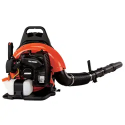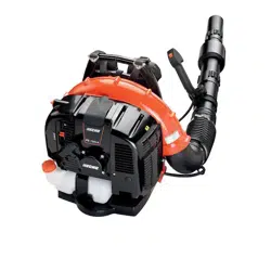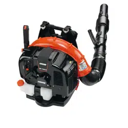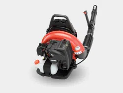
Power Blower
Operator's Manual
MODEL: PB-755S H
PB-755S T
WARNING
Users of this equipment risk injury to themselves and others if the unit is used
improperly and/or safety precautions are not followed. ECHO provides an opera-
tor’s manual. It must be read and understood for proper and safe operation. Failure
to do so could result in serious injury.
X7531122705
X753003325
02/12

2
CopyRight© 2012 By Echo, Incorporated
All Rights Reserved.
Table of ConTenTs
Introduction ................................................................2
- The Operator's Manual .......................................2
Safety .........................................................................3
Manual Safety Symbols and Important Information .3
- International Symbols ......................................... 3
- Personal Condition and Safety Equipment ......... 3
- Equipment ...........................................................6
Emission Control .......................................................6
Description ................................................................. 7
Contents .................................................................. 11
Assembly..................................................................12
- Install Blower Pipes PB-755SH ........................12
- Install Blower Pipes PB-755ST ........................13
Operation ..................................................................14
- Fuel ...................................................................14
- Starting Cold Engine .........................................16
- Starting Warm Engine .......................................17
- Stopping Engine ................................................17
- Operating Blower ..............................................18
Maintenance ............................................................. 19
- Skill Levels .......................................................19
- Maintenance Intervals .......................................19
- Air Filter ...........................................................20
- Fuel Filter ..........................................................20
- Spark Plug .........................................................21
- Cooling System .................................................21
- Exhaust System .................................................22
- Carburetor Adjustment ......................................23
- High Altitude Operation ................................23
Troubleshooting .......................................................25
Storage .....................................................................26
Specications ...........................................................27
Warranty Statement .................................................. 28
Servicing Information ..............................................32
- Parts/
Serial Number ...........................................32
- Service ..............................................................32
- ECHO Consumer Product Support ................... 32
- Warranty Card ................................................... 32
- Additional or Replacement Manuals ................32
Specications, descriptions and illustrative material in this
literature are as accurate as known at the time of publica-
tion, but are subject to change without notice. Illustrations
may include optional equipment and accessories, and may
not include all standard equipment.
InTroduCTIon
Welcome to the ECHO family. This ECHO product was designed and manufactured to provide long life and on-the-
job-dependability. Read and understand this manual. You will nd it easy to use and full of helpful operations tips and
SAFETY messages.
The operaTor's manual
Keep it in a safe place for future reference. Contains specications and
information for safety, operation, maintenance, storage, and assembly
specic to this product.
3
Power Blower
oPerator's Manual
safeTy
manual
safeTy symbols and ImporTanT InformaTIon
Throughout this manual and on the product itself, you will nd safety alerts and helpful, informational messages pre-
ceded by symbols or key words. The following is an explanation of those symbols and key words and what they mean to
you.
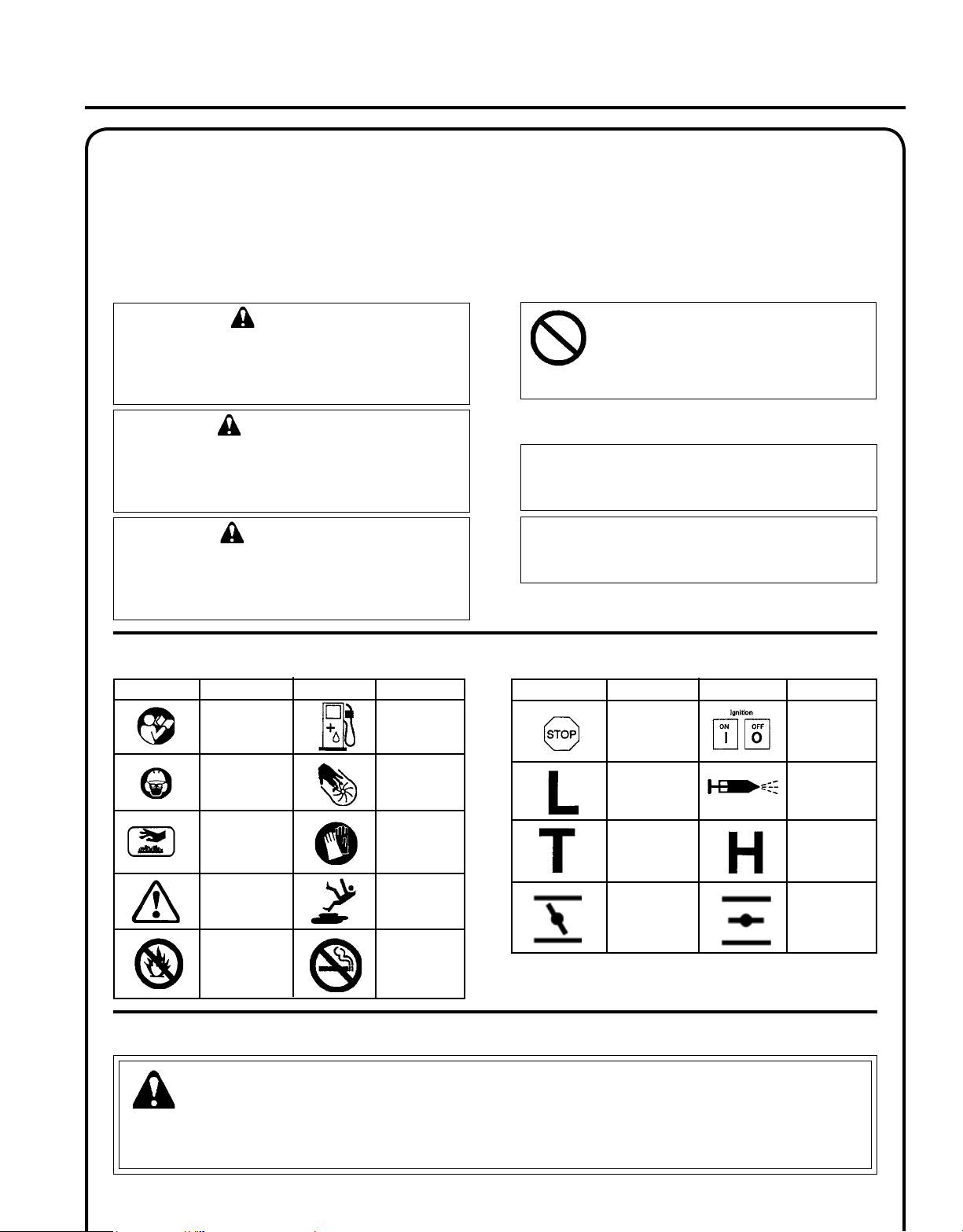
InTernaTIonal symbols
Symbol
description/application
Symbol form/shape
Symbol
description/application
Symbol form/shape
Read and understand
Operator's Manual.
Fuel and oil mixture
Hot
Surface
Wear eyes, ears and
head protection
Finger Severing
Safety/Alert
Wear hand
protection. Use
two handed.
DO NOT smoke
near fuel.
DO NOT allow
ames or sparks
near fuel.
Wear slip resis-
tant foot wear.
personal CondITIon and safeTy equIpmenT
WARNING
Users of this product risk injury to themselves and others if the unit is used improperly and/or safety precautions are
not followed. Proper clothing and safety gear must be worn when operating unit.
WARNING
The safety alert symbol accompanied by the word
“WARNING” calls attention to an act or condi-
tion which CAN lead to serious personal injury or
death if not avoided.
CIRCLE AND SLASH SYMBOL
This symbol means the specic action
shown is prohibited. Ignoring these prohi-
bitions can result in serious or fatal injury.
CAUTION
The safety alert symbol accompanied by the word
“CAUTION” calls attention to an act or condition
which may lead to minor or moderate personal
injury if not avoided.
NOTE
This enclosed message provides tips for use, care and
maintenance of the unit.
IMPORTANT
The enclosed message provides information neces-
sary for the protection of the unit.
DANGER
The safety alert symbol accompanied by the word
“DANGER” calls attention to an act or condition
which WILL lead to serious personal injury or
death if not avoided.
Symbol
description/application
Symbol form/shape
Symbol
description/application
Symbol form/shape
Carburetor adjustment
- Idle speed
Carburetor adjustment
- High speed mixture
Emergency stop
Carburetor adjustment
- Low speed mixture
Ignition
ON/OFF
Primer bulb
Choke Control
"Cold Start"
Position
(Choke Closed)
Choke Control
"Run"
Position
(Choke Open)

4
Physical Condition
Your judgment and physical dexterity may not be good:
• if you are tired or sick,
• if you are taking medication,
• if you have taken alcohol or drugs.
Operate unit only if you are physically and mentally well.
Eye Protection
Wear eye protection that meets ANSI Z87.1 or CE re-
quirements whenever you operate the unit.
Hand Protection
Wear no-slip, heavy-duty work gloves to improve your
grip on the blower handle. Gloves also reduce the trans-
mission of machine vibration to your hands.
Breathing Protection
Wear a facemask to protect against dust.
Hearing Protection
ECHO recommends wearing hearing protection whenever
unit is used.
Vibration and Cold
It is believed that a condition called Raynaud’s Phenomenon, which affects the ngers of certain individuals, may be
brought about by exposure to vibration and cold. Exposure to vibration and cold may cause tingling and burning sen-
sations, followed by loss of color and numbness in the ngers. The following precautions are strongly recommended,
because the minimum exposure, which might trigger the ailment, is unknown.
• Keep your body warm, especially the head, neck, feet, ankles,
hands, and wrists.
• Maintain good blood circulation by performing vigorous arm
exercises during frequent work breaks, and also by not smoking.
• Limit the hours of operation. Try to ll each day with jobs where
operating the unit or other hand-held power equipment is not
required.
• If you experience discomfort, redness, and swelling of the ngers
followed by whitening and loss of feeling, consult your physician
before further exposing yourself to cold and vibration.
Proper Clothing
Wear snug tting, durable clothing;
• Pants should have long legs, shirts with long sleeves.
• DO NOT WEAR SHORTS,
• DO NOT WEAR TIES, SCARVES, JEWELRY,
or clothing with loose or hanging items that could
become entangled in moving parts or surrounding
growth..
Wear sturdy work shoes with nonskid soles;
• DO NOT WEAR OPEN TOED SHOES,
• DO NOT OPERATE UNIT BAREFOOTED.
Wear no-slip, heavy duty work gloves.
Keep long hair away from engine and air intake. Retain
hair with cap or net.
Hot Humid Weather
Heavy protective clothing can increase operator fatigue
which may lead to heat stroke. Schedule heavy work for
early morning or late afternoon hours when temperatures
are cooler.
WARNING
The ignition components of this machine generate an electromagnetic eld during operation which may interfere
with some pacemakers. To reduce the risk of serious or fatal injury, persons with pacemakers should consult with
their physician and the pacemaker manufacturer before operating this machine. In the absence of such informa-
tion, ECHO does not recommend the use of ECHO products by anyone who has a pacemaker.

5
Power Blower
oPerator's Manual
DANGER
Do not operate this product indoors or in inadequately ventilated
areas. Engine exhaust contains poisonous emissions and can cause
serious injury or death.
Read the Manuals
• Provide all users of this equipment with the Operator’s Manual
for instructions on Safe Operation.
Clear the Work Area
• Spectators and fellow workers must be warned, and children and
animals prevented from coming nearer than 15 m (50 ft.) while
the unit is in use.
• Take wind conditions into account: avoid open doors and win-
dows.
• Do not point blower at people or animals.
Keep a Firm Grip
• Hold the front and rear handles with both hands, with thumbs
and ngers encircling the handles.
Keep a Solid Stance
• Maintain footing and balance at all times. Do not stand on slip-
pery, uneven or unstable surfaces. Do not work in odd positions
or on ladders. Do not over reach.
Avoid Hot Surfaces
• Keep exhaust area clear of ammable debris. Avoid contact dur-
ing and immediately after operation.
Repetitive Stress Injuries
It is believed that overusing the muscles and tendons of the ngers, hands, arms, and shoulders may cause soreness,
swelling, numbness, weakness, and extreme pain in those areas. Certain repetitive hand activities may put you at a high
risk for developing a Repetitive Stress Injury (RSI). An extreme RSI condition is Carpal Tunnel Syndrome (CTS), which
could occur when your wrist swells and squeezes a vital nerve that runs through the area.
Some believe that prolonged exposure to vibration may contribute to CTS. CTS can cause severe pain for months or
even years.
To reduce the risk of RSI/CTS, do the following:
• Avoid using your wrist in a bent, extended, or twisted position.
Instead try to maintain a straight wrist position. Also, when
grasping, use your whole hand, not just the thumb and index
nger.
• Take periodic breaks to minimize repetition and rest your hands.
• Reduce the speed and force with which you do the repetitive
movement.
• Do exercises to strengthen the hand and arm muscles.
• Immediately stop using all power equipment and consult a doc-
tor if you feel tingling, numbness, or pain in the ngers, hands,
wrists, or arms. The sooner RSI/CTS is diagnosed, the more
likely permanent nerve and muscle damage can be prevented.
6
equIpmenT CheCk
WARNING
Use only ECHO approved attachments. Serious injury may result from the use of a non-approved attachment combi-
nation. ECHO, INC. will not be responsible for the failure of cutting devices, attachments or accessories which have
not been tested and approved by ECHO. Read and comply with all safety instructions listed in this manual and safety
manual.
• Check unit for loose/missing nuts, bolts and screws. Tighten and/or replace as needed.
• Do not use blower if any part is missing or damaged.
• Have repairs done only by an authorized ECHO Service dealer.
• Do not use any attachment, accessory or replacement part unless it is recommended in this Operator's Manual.
WARNING
Moving parts can amputate ngers or cause severe injuries. Keep hands, clothing and loose objects away from all
openings.
• ALWAYS stop engine, disconnect spark plug, and make sure all moving parts have come to a complete stop
before removing obstructions, clearing debris, or servicing unit.
• DO NOT start or operate unit unless all guards and protective covers are properly assembled to unit.
• NEVER reach into any opening while the engine is running. Moving parts may not be visible through openings.
WARNING
Check fuel system for leaks due to fuel tank damage, especially if the unit is dropped. If damage or leaks are found,
do not use unit, otherwise serious personal injury or property damage may occur. Have unit repaired by an authorized
servicing dealer before using.
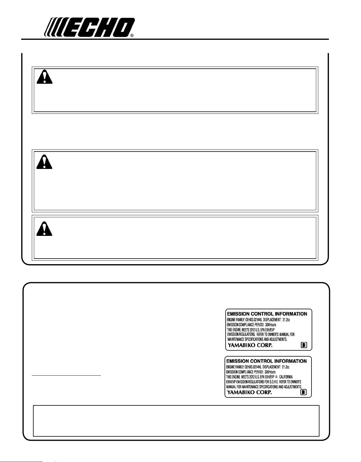
An Emission Control Label is located on the engine.
(This is an EXAMPLE ONLY, information on label varies
by engine FAMILY).
emIssIon ConTrol (exhausT & evaporaTIve)
EPA 2010 and Later and/or C.A.R.B. TIER III
PRODUCT EMISSION DURABILITY (EMISSION COMPLIANCE PERIOD)
The 300 hour emission compliance period is the time span selected by the manufacturer certifying the engine emis-
sions output meets applicable emissions regulations, provided that approved maintenance procedures are followed as
listed in the Maintenance Section of this manual.
The emission control system for the engine is EM (engine
modication) and, if the second to last character of the
Engine Family on the Emission Control Information label
(sample below) is “C”, “K”, or “T”, the emission control sys-
tem is EM and TWC (3-way catalyst). The fuel tank/fuel line
emission control system is EVAP (evaporative emissions).
Evaporative emissions for California models may only be
applicable to fuel tanks.

7
Power Blower
oPerator's Manual
desCrIpTIon
PB-755SH
Locate these safety decals on your unit. Make sure the decals are legible and that you understand and follow the instruc-
tions on them. If a decal cannot be read, a new one can be ordered from your ECHO dealer. See PARTS ORDERING
instructions for specic information.
Hot Decal (near mufer)
74 Category III
dB(A)
Measured at 50 ft. (15m) per ANSI B175.2
General Warning Decal (located on blower housing)
Sound Label (located on blower housing)
1
2
3
6
7
8
9
10
11
12
13
4
5

8
1. SPARK PLUG - Provides spark to ignite fuel mixture.
2. SAFETY DECAL - Lists important safety precautions.
3. SPARK ARRESTOR MUFFLER OR SPARK ARRESTOR MUFFLER WITH CATALYST - The mufer or
catalytic mufer controls exhaust noise and emission. The spark arrestor screen prevents hot, glowing particles of
carbon from leaving the mufer. Keep exhaust area clear of ammable debris.
4. CHOKE - Move lever up to "Cold Start" ( ) starting position and for emergency stopping. Move lever down to
Run position ( ).
5. PURGE BULB - Pumping purge bulb before starting engine draws fresh fuel from the fuel tank, purging air from
the carburetor. Pump purge bulb until fuel is visible and ows freely in the clear fuel tank return line. Pump purge
bulb an additional 4 or 5 times.
6. RECOIL STARTER HANDLE - Pull recoil handle slowly until starter engages, then quickly and rmly. When
engine starts, return handle slowly. DO NOT let handle snap back or damage to unit will occur.
7. FUEL TANK - Contains fuel and fuel lter.
8. FUEL TANK CAP - Covers and seals fuel tank.
9. AIR CLEANER - Contains replaceable air lter element.
10. HANDLE - Rotates downward for throttle control access. Spring loaded for exible operation.
11. BLOWER PIPES - Exclusive positive locking system.
12. SHOULDER HARNESS - Used to support unit on operator's back. The straps are adjustable.
13. THROTTLE POSITION LEVER/STOP SWITCH - Combination stop switch and variable speed throttle lever.
When the lever is moved all the way forward the blower is at Wide Open Throttle (W.O.T.). When the lever is
moved rearward to detent, the blower is at idle. When the lever is moved rearward past the idle detent the blower
will stop.

9
Power Blower
oPerator's Manual
17
16
3
6
5
4
7
8
9
PB-755ST
Locate these safety decals on your unit. Make sure the decals are legible and that you understand and follow the instruc-
tions on them. If a decal cannot be read, a new one can be ordered from your ECHO dealer. See PARTS ORDERING
instructions for specic information.
74 Category III
dB(A)
Measured at 50 ft. (15m) per ANSI B175.2
General Warning Decal (located on
blower housing)
Sound Label (located on blower
housing)
12
2
10
1
11
Hot Decal (near mufer)
13
14
15

10
1. SPARK PLUG - Provides spark to ignite fuel mixture.
2. SAFETY DECAL - Lists important safety precautions.
3. SPARK ARRESTOR MUFFLER OR SPARK ARRESTOR MUFFLER WITH CATALYST - The mufer or
catalytic mufer controls exhaust noise and emission. The spark arrestor screen prevents hot, glowing particles of
carbon from leaving the mufer. Keep exhaust area clear of ammable debris.
4. CHOKE - Move lever up to "Cold Start" ( ) starting position and for emergency stopping. Move lever down to
Run position ( ).
5. PURGE BULB - Pumping purge bulb before starting engine draws fresh fuel from the fuel tank, purging air from
the carburetor. Pump purge bulb until fuel is visible and ows freely in the clear fuel tank return line. Pump purge
bulb an additional 4 or 5 times.
6. RECOIL STARTER HANDLE - Pull recoil handle slowly until starter engages, then quickly and rmly. When
engine starts, return handle slowly. DO NOT let handle snap back or damage to unit will occur.
7. FUEL TANK - Contains fuel and fuel lter.
8. FUEL TANK CAP - Covers and seals fuel tank.
9. AIR CLEANER - Contains replaceable air lter element.
10. THROTTLE POSITION LEVER - Pull back to increase engine speed. Friction washers maintain throttle lever
setting.
11. STOP SWITCH - Slide switch mounted on top of handle. Move forward to run, back to stop.
12. HANDLE - Used by operator to direct and control air ow.
13. SHOULDER HARNESS - Used to support unit on operator's back. The straps are adjustable.
14. THROTTLE TRIGGER - Spring loaded to return to idle when released. During acceleration, press trigger gradu-
ally for best operating technique.
15. LOCKING KNOB - Allows operator to adjust handle position for optimum comfort and control.
16. BLOWER PIPES - Exclusive positive locking system.
17. FLEXIBLE PIPE - Allows for full range of movement.

11
Power Blower
oPerator's Manual
ConTenTs
PB-755S H
___ 1 - Power Head
___ 1 - Flex Pipe
___ 1 - Pipe w/swivel
___ 1 - Straight Pipe
___ 1 - Straight Pipe
___ 1 - Operator's Manual
___ 1 - Warranty Registration Card
___ 1 - Plastic Bag
___ 2 - Clamps w/screws
___ 1 - Stick Handle
___ 1 - Bolt 6x45
___ 1 - Washer 6
___ 1 - Wing Nut
___ 1 - Echo Power Blend X
TM
2-stroke oil sample
PB-755S T
___ 1 - Power Head
___ 1 - Flex Pipe
___ 1 - Pipe w/swivel
___ 1 - Straight Pipe
___ 1 - Straight Pipe
___ 1 - Operator's Manual
___ 1 - Warranty Registration Card
___ 1 - Plastic Bag
___ 2 - Clamps w/screws
___ 1 - Guide Loop
___ 1 - Echo Power Blend X
TM
2-stroke oil sample

12
assembly
PB-755SH
WARNING
Never perform maintenance or assembly procedures with engine
running or serious personal injury may result.
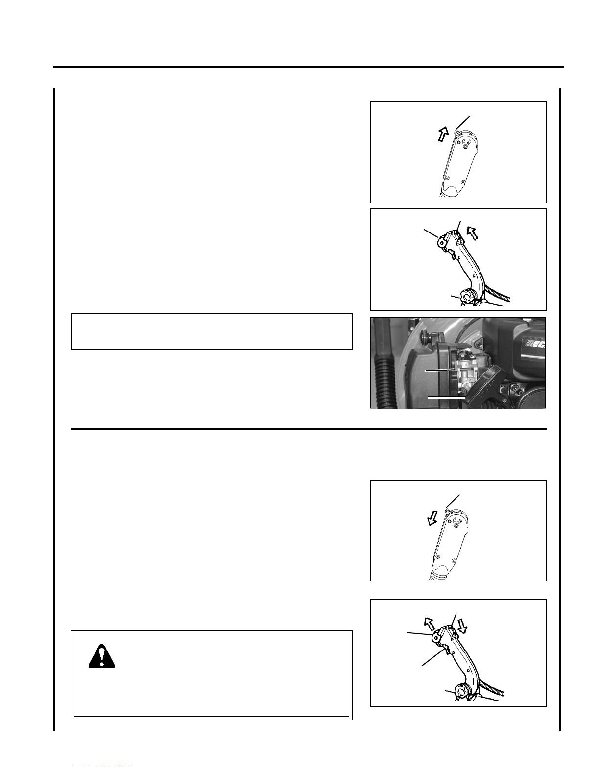
InsTall blower pIpes / sTICk handle
(
h)
1. Assemble clamps (A) onto both ends of exible pipe (B).
2. Assemble swivel pipe (C) into exible pipe (B) and tighten clamp
(A).
3. Assemble exible pipe (B) to elbow (D) on blower and tighten
clamp (A).
NOTE
A light lubricant may be used to ease assembly of exible pipe to
blower elbow.
4. Loosen wing nut (E) completely and open stick handle clamp.
5. Align notches (F) in handle clamp with tabs (G).
6. Slide stick handle onto swivel pipe (C). Stick handle should be
angled away from operator.
7. Position stick handle (H) for comfortable operation, and tighten
wing nut (E).
8. Assemble straight pipe (I) onto swivel pipe (C), until you feel
light resistance. Do not force connection. Hold swivel pipe and
turn straight pipe clockwise, engaging positive locking channels,
until connection is rm. Do not force connection.
9. Assemble straight pipe with decal (J) to straight pipe (I) as in step
8.
NOTE
Blower use will eventually loosen pipe connections. Exclusive
positive locking system allows pipes to be tightened. If loosening
occurs, remove two straight pipes and install according to instruc-
tions 8 & 9.
A
A
B
D
C
B
C
I
J
H
E
G
F
G

13
Power Blower
oPerator's Manual
PB-755ST
WARNING
Never perform maintenance or assembly procedures with engine
running or serious personal injury may result.
InsTall blower pIpes (T)
1. Place guide loop (G) across large clamp, and turn until clip fully
engages clamp band.
NOTE
Clamp with cable guide loop (G) ts large end of exible pipe (B).
2. Assemble clamps (A) onto both ends of exible pipe (B).
3. Assemble exible pipe (B) to elbow (D) on blower. Position
guide loop (G) on inside (blower side) of exible tube and tighten
clamp (A).
NOTE
A light lubricant may be used to ease assembly of exible pipe to
blower elbow.
NOTE
Hang handle freely from blower to assure throttle cable is not
twisted before installing handle (E).
4. Position cable between the elbow (D) and frame and along the top
of the exible pipe. Loosen knob (H) on handle (E). Align notch
in handle with tabs (F). Install onto swivel pipe (C) past long
ridges in pipe.
5. Assemble swivel pipe (C) into exible pipe (B) and tighten clamp
(A).
6. Clip throttle cable into throttle cable guide loop (G).
7. Move handle (E) to desired position. Tighten knob (H) hand tight.
8. Assemble straight pipe (I) onto swivel pipe (C), until you feel
light resistance. Do not force connection. Hold swivel pipe and
turn straight pipe clockwise, engaging positive locking channels,
until connection is rm. Do not force connection.
9. Assemble straight pipe with decal (J) to straight pipe (I) as in step
8.
NOTE
Blower use will eventually loosen pipe connections. Exclusive
positive locking system allows pipes to be tightened. If loosening
occurs, remove two straight pipes and install according to instruc-
tions 8 & 9.
G
G
E
B
H
F
D
G
A
A
B
C
G
E
I
J
C
E
H

14
WARNING
Operation of this equipment may create sparks that can start res. This unit is equipped with a spark arrestor to
prevent discharge of hot particles from the engine. Metal blade use also can create sparks if the blade strikes rocks,
metal, or other hard objects. Contact local re authorities for laws or regulations regarding re prevention require-
ments.
NOTICE: Use of unmixed, improperly mixed, or fuel older than 90 days, (stale fuel), may cause hard starting, poor
performance, or severe engine damage and void the product warranty. Read and follow instructions in the Storage
section of this manual.
fuel
WARNING
Alternative fuels, such as E-15 (15% ethanol), E-85 (85% ethanol) or any fuels not meeting ECHO requirements are
NOT approved for use in ECHO 2-stroke gasoline engines. Use of alternative fuels may cause performance prob-
lems, loss of power, overheating, fuel vapor lock, and unintended machine operation, including, but not limited to,
improper clutch engagement. Alternative fuels may also cause premature deterioration of fuel lines, gaskets, carbu-
retors and other engine components.
Fuel Requirements
Gasoline - Use 89 Octane [R+M/2] (mid grade or higher) gasoline known to be good quality. Gasoline may contain up to
10% Ethanol (grain alcohol) or 15% MTBE (methyl tertiary-butyl ether). Gasoline containing methanol (wood alcohol)
is NOT approved.
Two Stroke Oil - A two-stroke engine oil meeting ISO-L-EGD (ISO/CD 13738) and JASO FD Standards must be used.
ECHO brand premium Power Blend X
TM
Universal 2-Stroke Oil meets these standards. Engine problems due to inad-
equate lubrication caused by failure to use an ISO-L-EGD (ISO/CD 13738) and JASO FD certied oil, such as ECHO
premium Power Blend X
TM
, will void the two-stroke engine warranty.
operaTIon
IMPORTANT
Echo premium Power Blend X
TM
Universal 2-Stroke Oil may be mixed at 50:1 ratio for application in all Echo en-
gines sold in the past regardless of ratio specied in those manuals.
WARNING
Moving parts can amputate ngers or cause severe injuries. Keep hands, clothing and loose objects away from all
openings. Always stop engine, disconnect spark plug, and make sure all moving parts have come to a complete stop
before removing obstructions, clearing debris, or servicing unit. Blower housing may contain shredder blades and
other sharp edges that can cause serious injuries if touched, even if engine is off and blades are not moving. Wear
gloves to protect hands from sharp edges and hot surfaces.
15
Power Blower
oPerator's Manual
Handling Fuel
DANGER
Fuel is VERY ammable. Use extreme care when mixing, storing or handling or serious personal injury may result.
• Use an approved fuel container.
• DO NOT smoke near fuel.
• DO NOT allow ames or sparks near fuel.
• Fuel tanks/cans may be under pressure. Always loosen fuel caps slowly allowing pressure to equalize.
• NEVER refuel a unit when the engine is HOT or RUNNING!
• DO NOT ll fuel tanks indoors. ALWAYS ll fuel tanks outdoors over bare ground.
• DO NOT overll fuel tank. Wipe up spills immediately.
• Securely tighten fuel tank cap and close fuel container after refueling.
• Inspect for fuel leakage. If fuel leakage is found, do not start or operate unit until leakage is repaired.
• Move at least 3m (10 ft.) from refueling location before starting the engine.
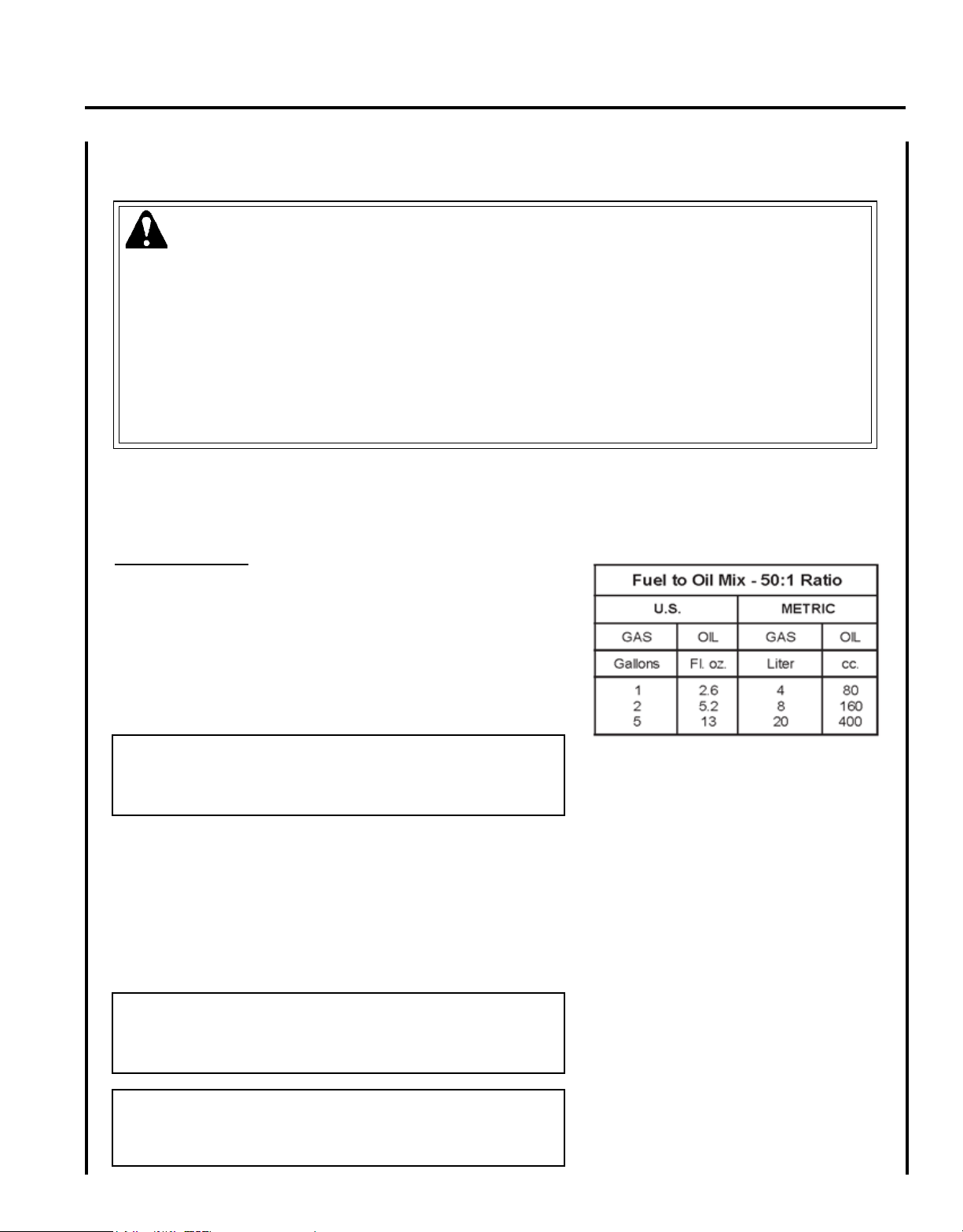
Mixing Instructions
1. Fill an approved fuel container with half of the required amount
of gasoline.
2. Add the proper amount of 2-stroke oil to gasoline.
3. Close container and shake to mix oil with gasoline.
4. Add remaining gasoline, close fuel container, and remix.
IMPORTANT
Spilled fuel is a leading cause of hydrocarbon emissions. Some
states may require the use of automatic fuel shut-off containers
to reduce fuel spillage.
After use
• DO NOT store a unit with fuel in its tank. Leaks can occur. Return
unused fuel to an approved fuel storage container.
Storage - Fuel storage laws vary by locality. Contact your local gov-
ernment for the laws affecting your area. As a precaution, store fuel in
an approved, airtight container. Store in a well-ventilated, unoccupied
building, away from sparks and ames.
IMPORTANT
Stored fuel ages. Do not mix more fuel than you expect to use in
thirty (30) days, ninety (90) days when a fuel stabilizer is added.
IMPORTANT
Stored two-stroke fuel may separate. ALWAYS shake fuel con-
tainer thoroughly before each use.

16
sTarTIng Cold engIne
• Recoil starter: Use short pulls - only 1/2-2/3 of rope length for start-
ing. Do not allow the rope to snap back in. Always hold the unit
rmly.
PB-755SH
1. Throttle Lever
Move throttle lever (A) to IDLE DETENT position.
PB-755ST
1. Throttle Lever/Stop Switch
Move throttle lever (A) forward to idle position. Slide stop switch
(B) forward to run position.
PB-755SH, PB-755ST
2. Choke
Move choke (C) up to "Cold Start" position ( ).
3. Purge Bulb
Pump purge bulb (D) until fuel is visible and ows freely in the
clear fuel tank return line. Pump bulb an additional 4 or 5 times.
4. Recoil Starter
Pull recoil starter handle (E) until engine res (5 or 6 pulls maxi-
mum).
5. Choke
Move choke (C) down to run position ( ), and if necessary,
restart engine.
NOTE
If engine does not start after 5 pulls, move choke to "Cold Start"
position, and repeat steps 4 & 5.
NOTE
Allow engine to warm up before use.
A
PB-755SH
PB-755ST
B
A
C
E
C
D
17
Power Blower
oPerator's Manual
sTarTIng warm engIne
PB-755SH
1. Throttle Lever
Move throttle lever (A) to IDLE DETENT position.
PB-755ST
1. Throttle Lever/Stop Switch
Move throttle lever (A) forward to idle position. Slide stop
switch (B) forward to run position.
PB-755SH, PB-755ST
2. Recoil Starter
Pull recoil starter handle (E) and engine should start. Do not use
choke (C).
NOTE
If engine does not start after 5 pulls, use cold start procedures.
A
sToppIng engIne
PB-755SH
1. Throttle Lever
Move throttle lever (A) to idle detent position and allow engine to
return to idle before shutting off engine.
2. Move throttle lever (A) to "O" (Stop) position.
PB-755ST
1. Throttle Trigger/Throttle Position Lever
Release throttle trigger (C). Move throttle position lever (A)
forward to idle position and allow engine to return to idle before
shutting engine off.
2. Stop Switch
Slide stop switch (B) to Stop position.
WARNING
If engine does not stop when stop switch is moved to STOP posi-
tion, close choke - COLD START position - to stall engine. Have
your ECHO dealer repair stop switch before using blower again.
A
PB-755SH
PB-755SH
PB-755ST
B
A
PB-755ST
B
A
C
C
E

18
Read the Safety Section carefully.
IMPORTANT
To avoid engine damage due to over-revving, do not block
blower pipe opening.
1. Use only during appropriate hours.
2. Allow the engine to warm up at a fast idle for a few minutes.
3. PB-755SH
Set engine speed with throttle lever (A).
PB-755ST
Control engine speed with throttle trigger (C), or throttle position
lever (A). Rotate throttle position lever forward for lower speed,
back for higher speed.
4. Use lower speed to blow dry leaves from walks, patios and
drives.
5. Additional speed may be necessary to clean grass and leaves from
a lawn or ower bed.
6. Higher speed may be necessary to move gravel, dirt, snow, bottles
or cans from a driveway, street, parking lot or stadium.
NOTE
Never use a higher speed setting than necessary to perform a task.
Remember, the higher the engine speed, the louder the blower
noise. Minimize dust by using blower at lower speeds and by
dampening material with water/mist when necessary. Keep debris
on your property.
Be Smart - be a good neighbor.
operaTIng blower
WARNING
Engine exhaust IS HOT, and contains Carbon Monoxide (CO), a
poison gas. Breathing CO can cause unconsciousness, serious in-
jury, or death. Exhaust can cause serious burns. ALWAYS position
unit so that exhaust is directed away from your face and body.
WARNING
Always wear safety glasses, hearing protection, a face lter mask
and take all safety precautions or serious personal injury may result.
Do not point the blower pipe in the direction of people or pets.
A
PB-755SH
PB-755ST
A
C
IMPORTANT
Use reduced speed only when performing light-duty tasks or
to comply with local noise regulations. Continuous low speed
operation may allow fuel/oil residue to build-up on the piston
and cause rapid build-up of carbon on the spark arrestor screen,
resulting in overheating and engine damage. To reduce harmful
build-up, run engine at wide open throttle for at least 5 minutes
every hour, and inspect/clean the spark arrestor screen after ap-
proximately 40 hours of operation.
19
Power Blower
oPerator's Manual
WARNING
Moving parts can amputate ngers or cause severe injuries. Keep hands, clothing and loose objects away from all
openings. Always stop engine, disconnect spark plug, and make sure all moving parts have come to a complete stop
before removing obstructions, clearing debris, or servicing unit. Wear gloves to protect hands from sharp edges and
hot surfaces.
maInTenanCe
Your ECHO blower is designed to provide many hours of trouble free service. Regular scheduled maintenance will help
your blower achieve that goal. If you are unsure or are not equipped with the necessary tools, you may want to take your
unit to an ECHO Service Dealer for maintenance. To help you decide whether you want to DO-IT-YOURSELF or have
the ECHO Dealer do it, each maintenance task has been graded. If task is not listed, see your ECHO Dealer for repairs.
skIll levels
Level 1 = Easy to do. Common tools may be required.
Level 2 = Moderate difculty. Some specialized tools may be required.
ECHO offers REPOWER
TM
Maintenance Kits and Parts to make your maintenance job easier.
maInTenanCe InTervals
COMPONENT / SYSTEM
MAINTENANCE
PROCEDURE
REQ'D
SKILL
LEVEL
DAILY OR
BEFORE USE
EVERY
REFUEL
3 MONTHS
OR 90
HOURS
YEARLY
600 HOURS
Air Filter Inspect/Clean
1
I / C * R *
Choke Shutter Inspect/Clean
1
I / C
Fuel Filter Inspect/Replace
1
I * I / R *
Fuel Cap Gasket Inspect/Replace
1
I * R *
Fuel System Inspect/Replace
1
I (1) * I (1) *
Spark Plug Inspect/Clean/Replace
1
I / C / R *
Cooling System Inspect/Clean
2
I / C
Muffler Spark Arrestor Inspect/Clean/Replace
2
I / C / R *
Cylinder Exhaust Port Inspect/Clean/Decarbon
2
I / C
Recoil Starter Rope Inspect/Clean
1
I / C *
Screws/Nuts/Bolts Inspect/Tighten/Replace
1
I *
MAINTENANCE PROCEDURE LETTER CODES:
I = INSPECT, R = REPLACE, C = CLEAN
IMPORTANT NOTE - Time intervals shown are maximum. Actual use and your experience will determine the
frequency of required maintenance.
MAINTENANCE PROCEDURE NOTES:
(1) Low evaporative fuel tanks DO NOT require regular maintenance to maintain emission integrity.
* All recommendations to replace are based on the finding of damage or wear during inspection.

20
aIr fIlTer
Level 1.
Parts required: Repower
TM
Tune Up Kit
1. Close choke (Cold Start Position [ ]). This prevents dirt from
entering the carburetor throat when the air lter is removed. Brush
accumulated dirt from air cleaner area.
2. Remove air lter cover. Brush dirt from inside cover.
3. Remove air lter and lightly brush debris from lter. Replace
lter if it is damaged, fuel soaked, very dirty, or the rubber sealing
edges are deformed.
4. If lter can be reused, be certain it:
• Fits tightly in the air lter cavity.
• Is installed with the original side out.
5. Install air lter cover.
fuel fIlTer
Level 1.
Parts required: Repower
TM
Tune Up Kit
DANGER
Fuel is VERY ammable. Use extreme care when mixing, storing
or handling, or serious personal injury may result.
1. Use a clean rag to remove loose dirt from around fuel cap and
empty fuel tank.
2. Use the “fuel line hook” to pull the fuel line and lter from the
tank.
3. Remove the lter from the line and install the new lter.
NOTE
Federal EPA regulations require all model year 2012 and later gasoline powered engines produced for sale in the
United States to be equipped with a special low permeation fuel supply hose between the carburetor and fuel tank.
When servicing model year 2012 and later equipment, only fuel supply hoses certied by EPA can be used to replace
the original equipment supply hose. Fines up to $37,500 may be enforced for using an un-certied replacement part.

21
Power Blower
oPerator's Manual
0.65 mm
(0.026 in.)
spark plug
Level 2.
Parts Required: Repower
TM
Tune Up Kit
IMPORTANT
Use only NGK BPM-8Y spark plug (BPMR-8Y in Canada)
otherwise severe engine damage may occur.
1. Remove spark plug and check for fouling, worn and rounded
center electrode.
2. Clean the plug or replace with a new one. DO NOT sand blast to
clean. Remaining sand will damage engine.
3. Adjust spark plug gap by bending outer electrode.
4. Tighten spark plug to 150-170 kgf • cm (130-150 in • lbf).
CoolIng sysTem
Level 2.
Parts Required: None, if you are careful.
IMPORTANT
To maintain proper engine operating temperatures, cooling air
must pass freely through the cylinder n area. This ow of air
carries combustion heat away from the engine.
Overheating and engine seizure can occur when:
• Air intakes are blocked, preventing cooling air from reaching the
cylinder.
• Dust and grass build up on the outside of the cylinder. This build up
insulates the engine and prevents the heat from leaving.
Removal of cooling passage blockages or cleaning of cooling ns is
considered “Normal Maintenance.” Any failure attributed to lack of
maintenance is not warranted.
Cleaning Grill
1. Remove accumulated debris from intake grill between backpack
frame and blower housing.
22
A
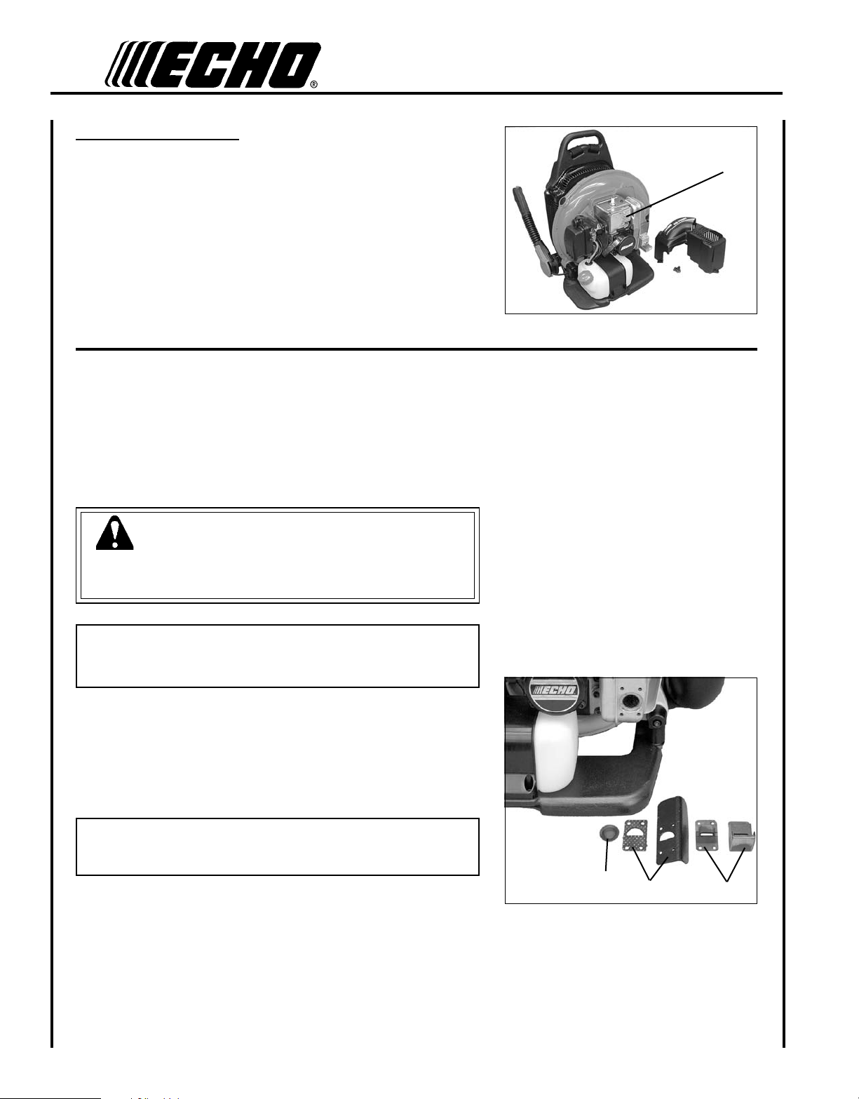
Cleaning Cylinder Fins
1. Remove spark plug lead from spark plug, and remove engine
cover.
2. Clean cylinder ns (A) to allow cooling air to pass freely.
3. Install engine cover and attach spark plug lead.
exhausT sysTem
Spark Arrestor Screen
Level 2.
Parts Required: Spark arrestor screen, Gaskets
WARNING
Do not perform maintenance on engine or mufer until engine and
mufer are completely cool, otherwise serious personal injury may
result.
IMPORTANT
Carbon deposits in mufer will cause a drop in engine output and
overheating. Spark arrestor screen must be checked periodically.
1. Remove spark plug lead from spark plug, and remove engine
cover.
2. Remove spark arrestor covers (A), gaskets (B), and spark arrestor
screen (C) from mufer. Replace screen if plugged with carbon
deposits.
NOTE
When cleaning carbon deposit, be careful not to damage the cata-
lytic element inside mufer.
3. Install spark arrestor screen and cover.
4. Install engine cover and attach spark plug lead.
A
B
C

23
Power Blower
oPerator's Manual
Exhaust Port Cleaning
Level 2
Parts Required: As needed: Heat Shield
1. Remove spark plug lead from spark plug, and remove engine
cover.
2. Place piston at top dead center. Remove mufer (A) and heat
shield (B).
3. Use a wood or plastic scraping tool to clean deposits from cylin-
der exhaust port.
IMPORTANT
Never use a metal tool to scrape carbon from the exhaust port.
Do not scratch the cylinder or piston when cleaning the exhaust
port. Do not allow carbon particles to enter the cylinder.
4. Inspect heat shield, and replace if damaged.
5. Install heat shield and mufer.
6. Tighten mufer mounting bolts (or nuts) to 95-130 in•lbf
(110-150 kgf•cm).
7. Install engine cover and attach spark plug lead.
8. Start engine, and warm to operating temperature.
9. Stop engine, and re-tighten mounting bolts to specications.
CarbureTor adjusTmenT
Engine Break-In
New engines must be operated a minimum duration of two tanks of fuel
break-in before carburetor adjustments can be made. During the break-
in period your engine performance will increase and exhaust emissions
will stabilize. Idle speed can be adjusted as required.
High Altitude Operation
This engine has been factory adjusted to maintain satisfactory starting,
emission, and durability performance up to 1,100 feet above sea level
(ASL) (96.0 kPa). To maintain proper engine operation and emission
compliance above 1,100 feet ASL the carburetor may need to be ad-
justed by an authorized ECHO service dealer.
IMPORTANT
If the engine is adjusted for operation above 1,100 feet ASL, the
carburetor must be re-adjusted when operating the engine below
1,100 feet ASL, otherwise severe engine damage may result.
A
B

24
A
Level 2.
Parts required: None.
NOTE
Every unit is run at the factory and the carburetor is set in compli-
ance with emission regulations. Carburetor adjustments, other than
idle speed, must be performed by an authorized ECHO dealer.
Before Adjustment
Check that:
• Air lter is clean and properly installed.
• Spark arrestor screen is free of carbon.
• Blower pipes are installed.
1. Start engine, run at idle for one minute.
2. Complete warm up by running at full throttle for 5 minutes, oper-
ating choke twice to clear air from carburetor chambers.
3. Check idle speed and reset if necessary. If a tachometer is avail-
able, idle speed screw (A) should be set to the specications
found on "Specications page" of this manual. Turn idle screw
(A) clockwise to increase idle speed; counter clockwise to de-
crease idle speed.

25
Power Blower
oPerator's Manual
TroubleshooTIng
DANGER
Fuel vapors are extremely ammable and may cause re and/or explosion. Never test for ignition spark by ground-
ing spark plug near cylinder plug hole, otherwise serious personal injury may result.
TRAHCGNITOOHSELBUORT
melborPkcehCsutatSesua
Cy
demeR
-sknarcenignE
/drahstrats
t'nseod
trats
roterubractaleuFroterubractaleufoNdeggolcreniartsleuF
deggolcenilleuF
roterubraC
ecalperronaelC
ecalperronaelC
relaedohcEruoyeeS
rednilyctaleuFrednilyctaleufoNroterubra
Cr
elaedohcEruoyeeS
leufhtiwtewrelffuMhcirooterutxiMleu
Fe
kohcnepO
retlifriaecalper/naelC
roterubractsujdA
relaedohcEruoyeeS
dnetakrapS
eriwgulpfo
krapsoNffohctiwspotS
melborplacirtcelE
hctiwskcolretnI
NOothctiwsnruT
relaedohcEruoyeeS
relaedohcEruoyeeS
gulptakrapSkrapsoNtcerrocnipagkrapS
nobrachtiwderevoC
leufhtiwdeluoF
evitcefedgulP
).ni620.0(mm56.ottsujdA
ecalperronaelC
ecalperronaelC
gulpecalpeR
,snurenignE
roseidtub
tonseod
etarelecca
ylreporp
retlifriAytridretlifriAraewlamro
Ne
calperronaelC
retlifleuFytridretlifleuFseudiser/stnanimatnoCni
leuf
ecalpeR
tnevleuFdeggulptnevleu
Fl
eufniseudiser/stnanimatno
Ce
calperronaelC
gulPkrapSnrow/ytridgulPraewlamro
Ne
calperrotsujdadnanaelC
roterubraCtnemtsujdareporpmInoitarbi
Vt
sujdA
metsySgnilooCmetsysgnilooC
deggulp/ytrid
ninoitarepodednetxE
snoitacolytsud/ytrid
naelC
neercSrotserrAkrapSneercsrotserrakrapS
deggulp
raewlamro
Ne
calpeR
seodenignE
knarcton
A/NA/Nmelborpenignelanretn
Ir
elaedohcEruoyeeS
,snurenignE
t'nseodrewolb
sirokrow
nevenu/kaew
epiprewolBdeggolcepiPsirbedfopu-dliu
Bg
olcnU
esoolepiPnoitarbi
Vn
ethgiT
degamadepiPesusiM/rae
We
calpeR

26
DANGER
Do not store in enclosure where fuel fumes may accumulate or reach an open ame or spark.
sTorage
WARNING
During operation the mufer or catalytic mufer and surrounding cover become hot. Always keep exhaust area clear
of ammable debris during transportation or when storing, otherwise serious property damage or personal injury may
result.
Long Term Storage (Over 30 Days)
Do not store your unit for a prolonged period of time (30 days or longer) without performing protective storage mainte-
nance which includes the following:
1. Store unit in a dry, dust free place, out of the reach of children.
2. Place the stop switch in the "STOP" position.
3. Remove accumulation of grease, oil, dirt and debris
from exterior of unit.
4. Perform all periodic lubrication and services that are
required.
5. Tighten all screws and nuts.
6. Drain fuel tank completely. Press purge bulb 6 - 7
times to remove remaining fuel from carburetor then
drain the tank again. Close choke, start and run the
engine until it stops due to lack of fuel.
7. A. Allow engine to cool then remove the spark plug
and pour 7 cc (1/4 oz.) of fresh, clean, two-stroke
engine oil into the cylinder through the spark
plug hole.
B. Pull the recoil starter handle 2-3 times to
distribute the oil inside the engine.
C. Observe the piston location through the spark
plug hole. Pull the recoil handle slowly until the
piston reaches the top of its travel and leave it
there.
8. Install the spark plug (do not connect ignition
cable).
9. Remove blower pipe assembly from unit.

27
Power Blower
oPerator's Manual
speCIfICaTIons
MODEL ---------------------------------------------------- PB-755SH, PB-755ST
Length ------------------------------------------------------ 375 mm (14.8 in.)
Width -------------------------------------------------------- 488 mm (19.0 in.)
Height ------------------------------------------------------- 527 mm (20.8 in.)
Weight (dry ------------------------------------------------- 11.9 kg (26.2 lb.)
Engine Type ------------------------------------------------ Air cooled, two-stroke, single cylinder gasoline engine
Displacement ----------------------------------------------- 63.3 cc (3.86 cu. in.)
Bore ---------------------------------------------------------- 48.0 mm (1.89 in.)
Stroke -------------------------------------------------------- 35.0 mm (1.38 in.)
Carburetor--------------------------------------------------- Diaphragm type w/purge
Ignition System -------------------------------------------- Flywheel Magneto, capacitor discharge ignition type
Spark Plug -------------------------------------------------- NGK BPM-8Y Gap 0.65 mm (0.026 in.)
Exhaust System -------------------------------------------- Spark arrestor mufer or spark arrestor mufer with catalyst
Fuel ---------------------------------------------------------- Mixed (Gasoline and Two-stroke Oil)
Fuel/Oil Ratio ---------------------------------------------- 50 : 1 Power Blend X
TM
ISO-L-EGD (ISO/CD 13738) and
J.A.S.O. M345- FD, two-stroke, air-cooled engine oil.
Gasoline ----------------------------------------------------- Use 89 Octane unleaded. Do not use fuel containing methyl
alcohol, more than 10% ethyl alcohol or 15% MTBE. Do not use
alternative fuels such as E-15 or E-85.
Oil ------------------------------------------------------------ Power Blend X
TM
Premium Universal 2-Stroke Oil
Fuel Tank Capacity ---------------------------------------- 2.0 lit. (67.7 US . oz.)
Recoil Starter System ------------------------------------- Automatic Recoil Starter Centrifugal Type
Idle Speed -------------------------------------------------- 2,600 (RPM)
Wide Open Throttle Speed ------------------------------- 7,050 (RPM)
Average Air Speed w/pipes (MPH) ---------------------- 87.17 m/sec (195 mph)
Maximum Air Speed (Measured at pipe end) --------- 104.16 KM/H (233 mph)
Average Air Volume (Measured at pipe end) ---------- 18.43 m
3/
min. (651 cu. ft./min.)
Sound Level at 50 ft. dB(A) scale per ANSI B175.2 - 74 dB(A)

28
warranTy sTaTemenTs
ECHO LIMITED WARRANTY STATEMENT FOR
PRODUCT SOLD IN USA AND CANADA BEGINNING 01/01/2010
ECHO'S RESPONSIBILITY
ECHO Incorporated’s Limited Warranty, provides to the original purchaser that this ECHO product is free from defects in material and workmanship.
Under normal use and maintenance from date of purchase, ECHO agrees to repair or replace at ECHO’s discretion, any defective product
free of charge at any authorized ECHO servicing dealer within listed below application time periods, limitations and exclusions. THIS LIMITED
WARRANTY IS ONLY APPLICABLE TO ECHO PRODUCTS SOLD BY AUTHORIZED ECHO DEALERS. IT IS EXTENDED TO THE ORIGINAL
PURCHASER ONLY, AND IS NOT TRANSFERABLE TO SUBSEQUENT OWNERS EXCEPT FOR EMISSION RELATED PARTS. Repair
parts and accessories replaced under this warranty are warranted only for the balance of the original unit or accessory warranty period. Any
damage caused by improper installation or improper maintenance is not covered by this warranty. All parts or products replaced under warranty
become the property of ECHO, Inc. This warranty is separate from the Emission control warranty statement supplied with your new product.
Please consult the Emission Control Warranty Statement for details regarding emission related parts. For a list of Authorized ECHO Dealers
refer to WWW.ECHO-USA.COM or call 1-800-432-ECHO.
OWNER’S RESPONSIBILITY
To ensure trouble free warranty coverage it is important that you register your ECHO equipment on-line at WWW.ECHO-USA.COM-
The owner shall demonstrate reasonable care and use, and follow preventative maintenance, storage, fuel and oil usage as prescribed in the
dealer for warranty repairs (within the applicable warranty period), and arrange for pick-up or return of your unit after the repairs have been
made. For your nearest authorized ECHO servicing dealer, call ECHO’s Dealer Referral Center, at 1-800-432-ECHO or you can locate an ECHO
servicing dealer at WWW.ECHO-USA.COM. Should you require assistance or have questions concerning ECHO’s Warranty Statement, you
can contact our Consumer Product Support Department at 1-800-673-1558 or contact us through the web at WWW.ECHO-USA.COM.
PRODUCT WARRANTY PERIOD
RESIDENTIAL APPLICATION
5 YEAR WARRANTY - All units for residential, or non-income producing use will be covered by this limited warranty for ve (5) years from
date of purchase.
EXCEPTIONS:
are warranted for the life* of the product on parts only.
producing use will be covered for failures due to defects in material or workmanship for a period of 60 days from original product
purchase date. Any misuse from contact with concrete, rocks, or other structures is not covered by this warranty.
manual for string head installation and maintenance instructions.
COMMERCIAL APPLICATION
1 YEAR WARRANTY - All Chain Saws, QuikVent Saws, and Cut-Off Saws for commercial, institutional, agricultural, industrial, or income
producing use will be covered by this limited warranty for one (1) year from the date of purchase.
2 YEAR WARRANTY - All other units for commercial, institutional, agricultural, industrial, or income producing use will be covered by this
limited warranty for two (2) years from the date of purchase.
EXCEPTIONS:
are warranted for the life* of the product on parts only.
agricultural, industrial, rental, or income producing will be covered for failures due to defects in material or workmanship for a period
of 30 days from original product purchase date. Any misuse from contact with concrete, rocks, or other structures is not covered by
this warranty.
manual for string head installation and maintenance instructions.
RENTAL APPLICATION - 90 DAYS WARRANTY
* section of
this warranty statement for “Life”

29
Power Blower
oPerator's Manual
PURCHASED REPAIR PARTS, SHORT BLOCKS AND ACCESSORIES
ATTENTION TWO-STROKE ENGINE POWER PRODUCT OWNERS
This ECHO two-stroke engine power product is a quality-engineered unit which has been manufactured to exact tolerances to provide superior
performance. To help ensure the performance of the unit, it is required to use two-stroke oil which meets the ISO-L-EGD Standard per ISO/CD
13738 and JASO M345FD Standards. ECHO Power Blend™ Two-Stroke Oil
L-EGD (ISO/CD 13738) and JASO M345FD Standards. The use of two-stroke oils designed for other applications, such as for outboard motors
or lawnmowers can result in severe engine damage, and will void your two-stroke engine limited warranty.
THIS WARRANTY DOES NOT COVER DAMAGE CAUSED BY:
that do not meet the ISO-L-EGD (ISO/CD 13738) and JASO M345FD
Standards. Engine problems due to inadequate lubrication caused by failure to use an ISO-L-EGD compliant and JASO M345FD registered
oil, will void the two-stroke engine limited warranty. meets the ISO-L-EGD and JASO M345FD
Standard. Emission related parts are covered for 5 years residential use or 2 years commercial use regardless of two-stroke oil used, per
the statement listed in the EPA or California Emission Defect Warranty Explanation.
. Only use gasoline which
contains . Gasohol which contains a maximum
is also approved. The prescribed mixing ratio of gasoline to oil is listed on the ECHO oil label and covered in your operator’s manual.
engine speeds as listed in your operator’s manual.
of unauthorized attachments.
manual. Preventative maintenance as outlined in the operators manual is the customer’s responsibility.
warranty period.
parts and other items are not warranted, including but not limited to: lubricants, starter cords, and engine tune-ups.
Manuals.
screen.
with recommended grease or oil change intervals.
®
beyond recommended capacity.
failure occur, the product should not be used, but delivered as is to an authorized ECHO servicing dealer.
It is a dealer’s and/or customer’s responsibility to complete and return the warranty registration card supplied with your ECHO product or by visiting
WWW.ECHO-USA.COM
ECHO servicing dealer for warranty service. Proof of purchase rests solely with the customer. Some states do not allow limitations on how long
an implied warranty lasts, so the above limitations may not apply to you. Some states do not allow the exclusion or limitation of incidental or
Incorporated, 400 Oakwood Rd., Lake Zurich, IL 60047.
DISCLAIMER OF IMPLIED WARRANTIES
OR USE and any implied warranty of MERCHANTABILITY
99922201032
11/18/2011

30
ECHO INCORPORATED EMISSION CONTROL WARRANTY STATEMENT
FOR ECHO AND SHINDAIWA BRANDS
The Environmental Protection Agency (EPA) and the California Air Resources Board (C.A.R.B.) and ECHO Incorporated (ECHO Inc.) are pleased
to explain the emission control system warranty on your 2010 and later equipment/small off-road engine (SORE). New equipment/SORE must be
designed, built and equipped to meet stringent EPA and C.A.R.B. anti-smog standards. ECHO Inc. must warrant the emission control system on
your equipment/SORE for the periods of time listed below, provided there has been no abuse, neglect or improper maintenance of your equipment/
SORE. Your emission control system may include parts such as: carburetor, fuel-injection system, ignition system, catalytic converter/mufer, fuel
tank, fuel feed lines, fuel cap assembly, spark plug, air lters, and other associated components. Where a warrantable condition exists, ECHO
Inc will repair your equipment/SORE at no cost to you including diagnosis, parts and labor. The Emission Control System warranty is extended
to the original owner including all subsequent owners.
MANUFACTURER'S WARRANTY COVERAGE:
The emission control system is warranted for 2 years or the length of the ECHO Inc. warranty, whichever is longer. If any emission-related part
on your equipment is defective, the part will be repaired or replaced by ECHO Inc. or its Authorized Service Representative.
OWNER'S WARRANTY RESPONSIBILITIES:
As the equipment/SORE owner, you are responsible for the performance of the required maintenance listed in your Operator's Manual. ECHO
Inc. recommends that you retain all receipts covering maintenance on your equipment/SORE however, ECHO Inc. cannot deny warranty solely
for the lack of receipts or for your failure to ensure the performance of all scheduled maintenance. As the equipment/SORE owner, you should be
aware that ECHO Inc. may deny you warranty coverage if your equipment/SORE or a part has failed due to abuse, neglect, improper maintenance
or unapproved modications.
You are responsible for presenting your equipment/SORE to an ECHO Inc. authorized service representative as soon as a problem exists. The
warranty repairs should be completed in a reasonable amount of time, not to exceed 30 days. If a warrantable condition exists and there is no
Authorized Dealer within 100 miles, ECHO Inc. will pay to ship the unit to the nearest authorized dealer. If you have questions regarding your
warranty coverage, you should contact ECHO Inc. at 1-800-673-1558, web site WWW.ECHO-USA.COM or contact Shindaiwa at 1-877-986-
7783, web site WWW.SHINDAIWA.COM.
WHAT DOES THIS WARRANTY COVER?
ECHO Inc. warrants that your equipment/SORE was designed, built and equipped to conform with applicable EPA and C.A.R.B. emissions
standards and that your equipment/SORE is free from defects in material and workmanship that would cause it to fail to conform with applicable
requirements for 2 years or the length of the ECHO Inc. warranty, whichever is longer. The warranty period begins on the date the product is
purchased by an end user.
HOW WILL A COVERED PART BE CORRECTED?
If there is a defect in a part covered by this warranty, any ECHO Inc. Authorized Service Dealer will correct the defect. You will not have to pay
anything to have the part adjusted, repaired or replaced. This includes any labor and diagnosis for warranted repairs performed by the dealer. In
addition, engine parts not expressly covered under this warranty but whose failure is a result of a failure of a covered part will be warranted.
WHAT PARTS ARE COVERED?
Any applicable emission related part not scheduled for "required maintenance" will be repaired or replaced within the warranty period. The repaired
or replaced part will be warranted for the remaining ECHO Inc. warranty period.
Any warranted part that is scheduled only for regular inspection in the written instructions supplied is warranted for the warranty period stated
above. Any such part repaired or replaced under warranty will be warranted for the remaining ECHO Inc. warranty period.
Any emission related part scheduled for replacement during "required maintenance" is warranted for the period of time prior to the rst scheduled
replacement point for that part. Any such part repaired or replaced under warranty shall be warranted for the remainder of the period prior to the
rst scheduled replacement point for that part.
Any manufacturer-approved replacement part may be used in the performance of any warranty maintenance or repairs on emission related parts,
and must be provided without charge if the part is still under warranty.
Any replacement part that is equivalent in performance and durability may be used in non-warranty maintenance or repairs, and shall not reduce
the warranty obligations of the manufacturer.
Throughout the equipment/SORE warranty period, ECHO Inc. will maintain a supply of warranted parts sufcient to meet the expected demand
for such parts.
SPECIFIC EMISSION RELATED WARRANTED PARTS:
• Electronic Ignition System • Spark Plug
• Catalytic Converter / Mufer Assembly • Carburetor (complete assembly or replaceable components)
• Choke • Fuel-Injection Assembly (or replaceable components)
• Fuel Tank • Fuel Cap Assembly
• Air Filter • Fuel Feed Line (and associated clamps/connectors as applicable)
WHAT IS NOT COVERED?
Any failure caused by abuse, neglect, improper maintenance, unapproved modications, use of unapproved add-on parts/modied parts or
unapproved accessories.
This Emission Control Warranty is valid only for the U.S.A., it's Territories, and Canada.
99922201033
01/2010

31
Power Blower
oPerator's Manual
noTes

DEALER?
Call
1-800-432-ECHO
1-800-432-3246
or
www.echo-usa.com
CONSUMER PRODUCT
SUPPORT
1-800-673-1558
8:30 - 4:30 Mon - Fri C.S.T.
ECHO, INCORPORATED
400 OakwOOd ROad
Lake ZuRich, iL 60047
www.echo-usa.com
(T) P04011001001/P04011999999
(T) P04112001001/P04112999999
(H) P04311001001/P04311999999
(H) P04412001001/P04412999999
addITIonal or replaCemenT manuals
Replacement Operator, Safety Manuals, and Parts Catalogs are available from your ECHO dealer or at www.echo-
usa.com or by contacting ECHO Inc., 400 Oakwood Road, Lake Zurich, IL 60047 (800-673-1558). Always check the
ECHO Web Site for updated information.
Safety Videos are available from your Echo dealer. A $5.00 shipping charge will be required for each video.
servICIng InformaTIon
parTs
/serIal number
Genuine ECHO Parts and ECHO REPOWER™ Parts and Assemblies
for your ECHO products are available only from an Authorized ECHO
Dealer. When you do need to buy parts always have the Model Number
and Serial Number of the unit with you. You can nd these numbers
on the engine housing. For future reference, write them in the space
provided below.
Model Number _____________ Serial Number ____________
servICe
An Authorized ECHO Service Dealer must perform Service of this
product during the warranty period. For the name and address of the
Authorized ECHO Service Dealer nearest you, ask your retailer or
call: 1-800-432-ECHO (3246). Dealer information is also available on
our Web Site. When presenting your unit for Warranty service/repairs,
proof of purchase is required.
eCho Consumer produCT supporT
If you require assistance or have questions concerning the applica-
tion, operation or maintenance of this product you may call the ECHO
Consumer Product Support Department at 1-800-673-1558 from 8:30
am to 4:30 pm (Central Standard Time) Monday through Friday. Before
calling, please know the model and serial number of your unit.
warranTy regIsTraTIon
To ensure trouble free warranty coverage it is important that you regis-
ter your ECHO equipment on-line at www.echo-usa.com or by lling
out the warranty registration card supplied with your unit. Registering
your product conrms your warranty coverage and provides a direct
link between you and ECHO if we nd it necessary to contact you.