Loading ...
Loading ...
Loading ...
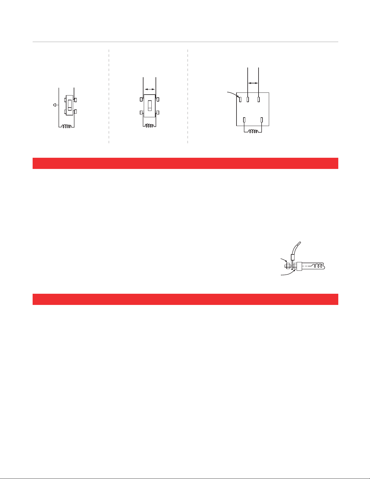
Connect the High Temperature Stainless Ring Terminal on the wire ends
to the element studs located on both ends of the tube. Use a thin 11/32"
wrench to hold inside nut. Nuts must make a tight connection.
GENERAL NOTES
1. INFRATECH QUARTZ TUBE ELECTRIC HEATERS are furnished with wall/ ceiling mount swivel brackets. These
brackets may be discarded when the heater is hung with chains or other special bracketing.
2. See sales literature and price list for full listing of models, descriptions, amperages, and voltages. At times, especially
when the mounting height must be quite low, an increased number of smaller heaters can help prevent overheating.
3. Heaters up to 15 AMPS can be used with a simple INF controller. This low cost controller, which is actually an infinite
switch, gently pulses the heat on and off.
4. For comfort heating, the best solution is to heat from two sides rather than from just one side. However, there are times
when this is not practical.
5. Areas covered are approximate dimensions and will vary depending on prevailing conditions and personal comfort levels.
5
REPLACEMENT ELEMENT INSTALLATION
Step 1: Check UL/CE label on heater for proper voltage.
Step 2: Remove two end reflectors.
Step 3: Open element clips at each end of the heater and
carefully install the quartz tube. Remove one nut from end
of element. Slip on wire over element screw. Replace nut.
NOTE: Hold element ceramic firmly while tightening nut
to prevent damage to element. Nut should be tightened
snug, a loose connection can cause element to short or
fail. Connect other side of element in like manner. Close
element clips over tube.
Step 4: Replace end reflectors.
Step 5: If necessary, clean tube and reflector with alcohol
or equivalent.
Step 6: Snap on protective grill provided.
HEATING ELEMENT
OFF
ON
OFF
ON
HEATER
TOP
P L1 L2
H2H1
HEATER
FOR 115V. PILOT
LIGHT IF USED
11/32" INSIDE NUT
SNUG TO CERAMIC
11/32" OUTSIDE NUT
REAR VIEW OF
CONTROLLER FOR
MAX. 15 AMF
LOAD ONLY
"TOP" MARKED ON
REAR OF CONTROL
MUST BE INSTALLED
IN AN UP POSITION
240 V.
240 V.
WHITE
BLACK 115 V.
TYPICAL WIRING OPTIONS
HEATING ELEMENT
OFF
ON
OFF
ON
HEATER
TOP
P L1 L2
H2H1
HEATER
FOR 115V. PILOT
LIGHT IF USED
11/32" INSIDE NUT
SNUG TO CERAMIC
11/32" OUTSIDE NUT
REAR VIEW OF
CONTROLLER FOR
MAX. 15 AMF
LOAD ONLY
"TOP" MARKED ON
REAR OF CONTROL
MUST BE INSTALLED
IN AN UP POSITION
240 V.
240 V.
WHITE
BLACK 115 V.
TYPICAL 120V WIRING
FOR A SINGLE POLE SWITCH
TYPICAL 240V WIRING FOR
A TWO POLE SWITCH
WIRING FOR OPTIONAL 120V/240V CONTROLS
Loading ...
Loading ...
Loading ...