Gas Range (GR) Series
Gas Range (GR) Series
General Information
1-2
#822634 - Revision A - January, 2013
This manual is designed to be used by Authorized Service Personnel only. Wolf Appliance, Inc., assumes
no responsibility for any repairs made to Wolf appliances by anyone other than Authorized Service
Technicians.
IMPORTANT SAFETY INFORMATION
Below are the Product Safety Labels used in this manu-
al. The "Signal Words" used are WARNING and
CAUTION.
Please note that these safety labels are placed in areas
where awareness of personal safety and product safety
should be taken and lists the precautions to be taken
when the signal word is observed.
INTRODUCTION
This Technical Service Manual has been compiled to provide the most recent technical service information about the
this series. This information will enable the service technician to troubleshoot and diagnose malfunctions, perform
necessary repairs, and return an appliance to proper operational condition.
The service technician should read the complete instructions contained in this Service Manual before initiating any
repairs on a Wolf Appliance.
Some information in Section 3 (Theory of Operation) has been provided by the American Gas Association and
reprinted with AGA’s approval.
INDICATES THAT HAZARDOUS OR UNSAFE
PRACTICES COULD RESULT IN SEVERE PERSON-
AL INJURY OR DEATH.
Indicates that hazardous or unsafe practices could
result in minor personal injury or product and/or
property damage
.
In addition, please pay attention to the signal word
“NOTE”, which highlights especially important informa-
tion within each section.
The information and images are the copyright property of Wolf Appliance, Inc., an affiliate of Sub-Zero, Inc. Neither
this manual nor any information or images contained herein may be copied or used in whole or in part without the
express written permission of Wolf Appliance, Inc., an affiliate of Sub-Zero, Inc. © Wolf Appliance, Inc. all rights
reserved.
TECHNICAL ASSISTANCE
If you should have any questions regarding the appli-
ance and/or this manual, please contact:
Wolf Appliance, Inc.
ATTN: Service Department
P.O. Box 44988
Madison, WI 53744 - 4988
Customer Assistance
Phone #: (800) 332 - 9513
Facsimile #: (608) 441 - 5887
Technical Assistance
(For Technicians in Customer’s Homes Only)
Phone #: (800) 919 - 8324
Warranty Claims
Phone #: (800) 404 - 7820
Facsimile #: (608) 441 - 5886
Service Department e-mail Address:
Main Office Hours:
8:00 AM to 5:00 PM Central Time
Monday through Friday
(24/7 Phone Coverage)
General Information
Gas Range (GR) Series
Gas Range (GR) Series
1-5
#822634 - Revision A - January, 2013
TWO & FIVE YEAR Warranty Summary
• Two year TOTAL PRODUCT warranty, parts and
labor.
• Limited Parts Only Warranty for the 3rd through 5th
year on the following parts only:
• Gas Burners (excluding appearance)
• NOTE: Stainless Steel doors, panels and product
frames are covered by a limited 60 day parts and
labor warranty for cosmetic defects.
Warranty Details:
The warranty applies only to products installed for nor-
mal residential use. The warranty applies only to prod-
ucts installed in the United States or Canada.
Warranty Notes:
• All warranties begin at the time of the unit's initial
installation.
• All Warranty and Service information collected by
Wolf Appliance, Inc. is arranged and stored under
the unit serial number and/or the customer's name.
Please note that Wolf Appliance, Inc. requests that
you have the model and serial number available
whenever contacting the factory or parts distributor.
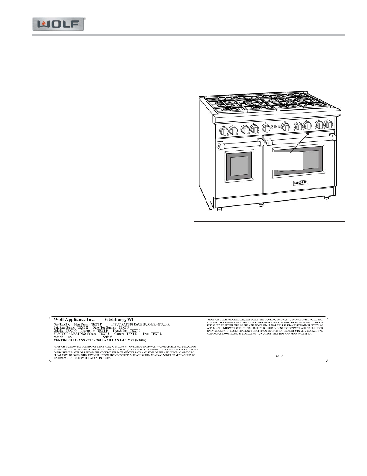
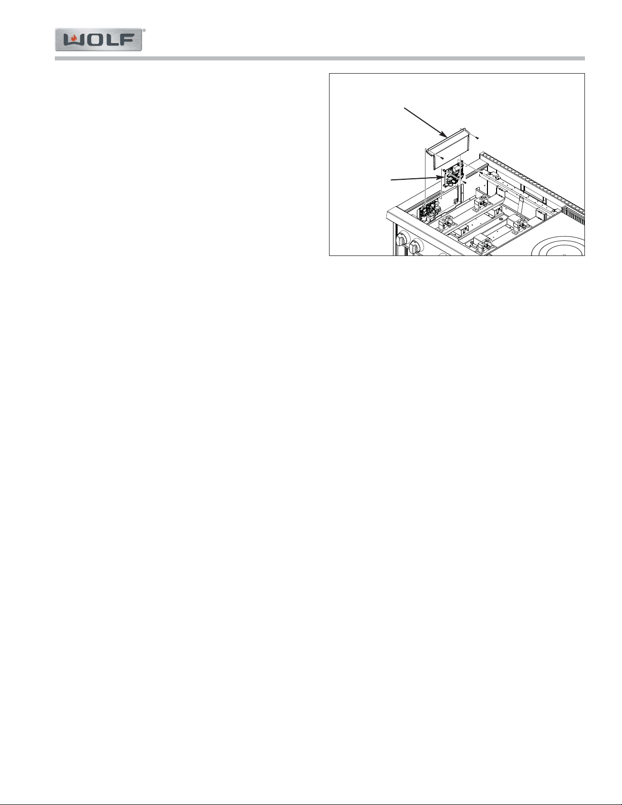
• See Figure 1-1 for typical serial plate layout.
• See Figures 1-2 for serial plate location, between
door and bull nose.
Figure 1-2. The serial plate is located above the
door
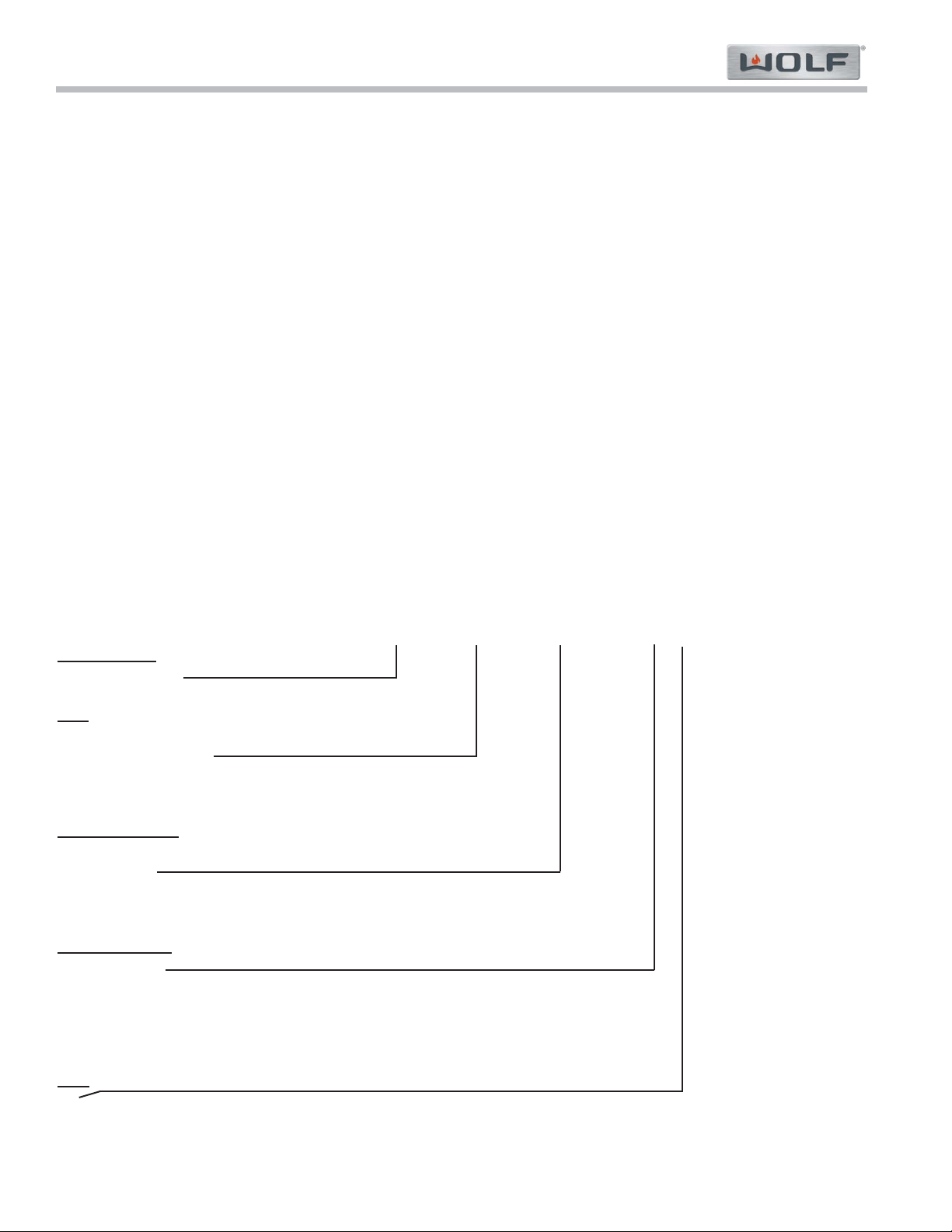
Figure 1-1. Typical Serial Plate Layout
Serial/Rating
Plate
WARRANTY INFORMATION
This page contains a summary of the 2 and 5 Year Warranty that is supplied with every Wolf product installed for
non-commercial use..
Gas Range (GR) Series
Gas Range (GR) Series
General Information
1-6
#822634 - Revision A - January, 2013
MODEL FEATURES
All Gas Ranges:
Oven burners input rated at 18,000 (18” oven) and 30,000 BTU (30” oven). Infrared Oven Broiler input rated at
18,000 BTU.
Some models:
Charbroiler rated at 16,000 BTU input. Griddle rated at 13,000 BTU (LP) / 15,000 BTU (Nat.) input. French Top
rated at 15,000 BTU input.
GAS RANGE FEATURES:
• Natural or LP gas models
• Classic stainless steel exterior
• Red control knobs (optional black or stainless steel knobs available)
• Chrome bezels surround all knobs
• Dual stacked burners with automatic re-ignition at all settings
• Cast iron porcelain coated grates
• Door windows and interior lights in ovens
• Porcelain oven interior
• 1" (25 mm) adjustable stainless steel legs in front and adjustable rear casters
• Full side panels (Skirt or Leg Covers are Sales Accessories)
• High altitude conversion kit available
• Optional risers – 5" (127 mm), 10" (254 mm) and 20" (508 mm) with shelf
MODEL NUMBER KEY
Refer to this key for an example of the model numbers.
Model: GR 36 4 C - LP
Product Type
GR - Gas Range
Size
30 - 30 inch wide unit
36 - 36 inch wide unit
48 - 48 inch wide unit
60 - 60 inch wide unit
Surface Burners
2 - 2 Burners
4 - 4 Burners
6 - 6 Burners
8 - 8 Burners
Model Features
C - Charbroiler
G - Griddle
F - French Top
DG - Double Griddle
DC - Double Charbroiler
Fuel
LP - Liquid Propane Gas will be indicated by -LP at the end of the model number. For example: GR364C-LP
NOTE: If model number does not have “-LP” at the end, then the unit is Natural Gas.
General Information
Gas Range (GR) Series
Gas Range (GR) Series
1-7
#822634 - Revision A - January, 2013
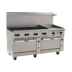
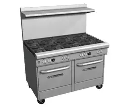
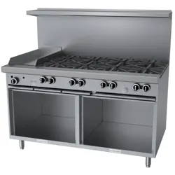
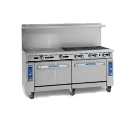
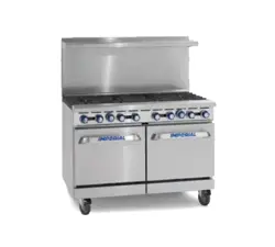
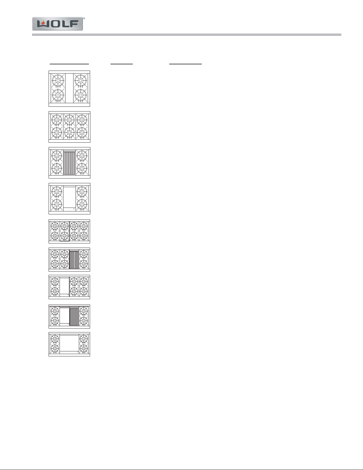
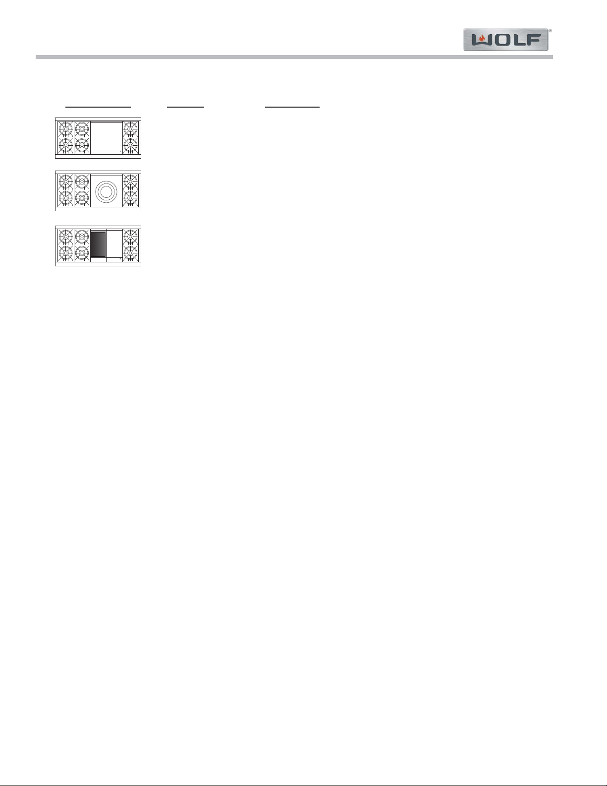
TOP CONFIGURATIONS OF 30”, 36” and 48” GAS RANGES
Configuration Model # Description
GR304 Gas Range 30'' - 4 Burners
GR366 Gas Range 36'' - 6 Burners
GR364C Gas Range 36'' - 4 Burners - w/11'' Charbroiler
GR364G Gas Range 36'' - 4 Burners - w/11'' Griddle
GR488 Gas Range 48'' - 8 Burners
GR486C Gas Range 48'' - 6 Burners - w/11'' Charbroiler
GR486G Gas Range 48'' - 6 Burners - w/11" Griddle
GR484CG Gas Range 48'' - 4 Burners - w/11" Charbroiler & 11" Griddle
GR484DG Gas Range 48'' - 4 Burners - w/22" Griddle
NOTE: If model number does not have “-LP” at the end, then the unit is Natural Gas.
Gas Range (GR) Series
Gas Range (GR) Series
General Information
1-8
#822634 - Revision A - January, 2013
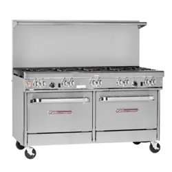
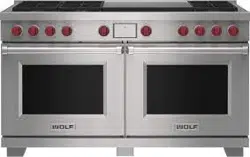
TOP CONFIGURATIONS OF 60” RANGE
Configuration Model # Description
GR606DG Gas Range 60'' - 6 Burners - w/22'' Griddle
GR606F Gas Range 60'' - 6 Burners - w/22'' Frenchtop
GR606CG Gas Range 60'' - 6 Burners - w/11'' Charbroiler & 11'' Griddle
NOTE: If model number does not have “-LP” at the end, then the unit is Natural Gas.
Gas Range (GR) Series
Gas Range (GR) Series
Installation Information
2-2
#822634 - Revision A - January, 2013
INSTALLATION INFORMATION
NEVER USE OPEN FLAMES TO CHECK FOR GAS
LEAKS. ONLY USE A COMMERCIAL LEAK DETEC-
TION SOLUTION OR SOAP SUDS AROUND GAS
CONNECTIONS TO CHECK FOR LEAKS. DO NOT
USE LIQUID NEAR VALVE STEMS.
Gas Supply
Installation must conform with local codes or, in the
absence of local codes, with the National Fuel Gas
Code.
Locate the gas supply within the shaded area shown in
the illustration for your specific model on the following
pages. The range is equipped for use with natural or liq-
uid propane (LP) gas. It is design certified by the
Canadian Standards Association (CSA) for natural or
LP gases. The product rating plate has information on
the type of gas that should be used. If this information
does not agree with the type of gas available, check
with the local gas supplier.
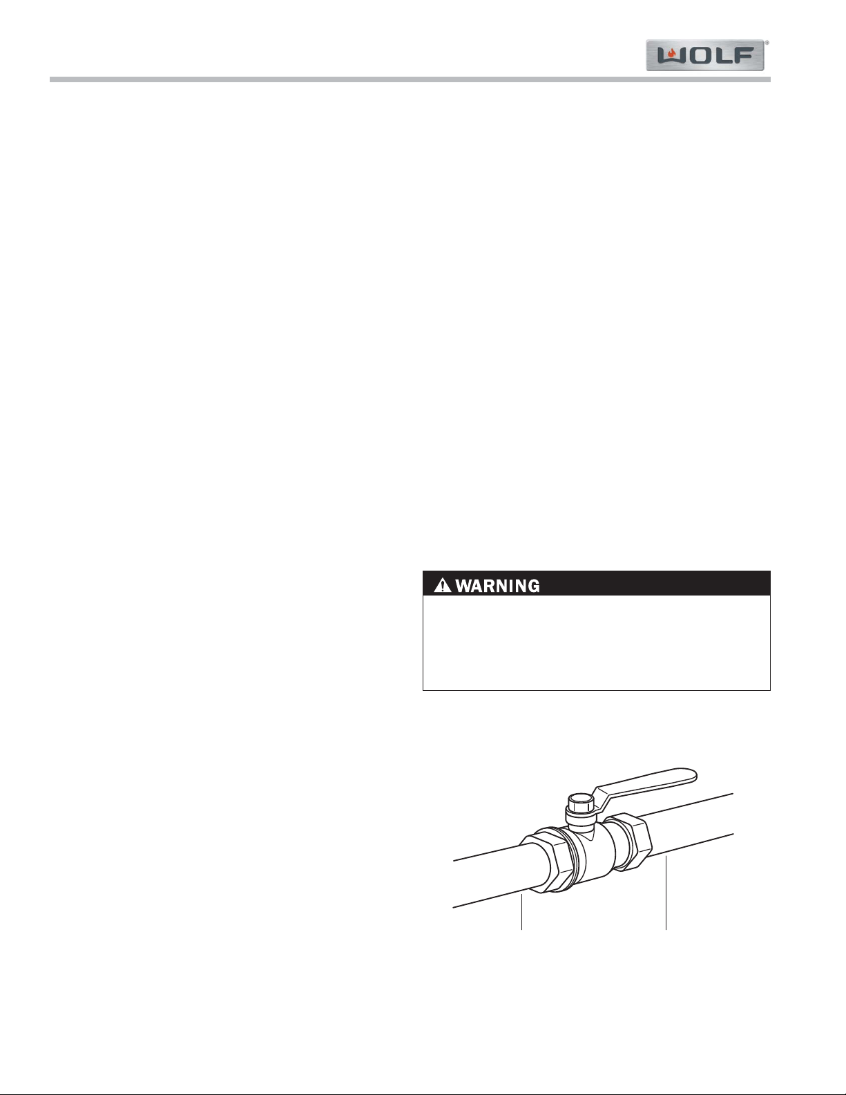
The range must be connected to a regulated gas sup-
ply. The supply line must be equipped with an
approved external gas shut-off valve located near the
range in an accessible location. Do not block access to
the shut-off valve. (See Figure 2.1)
A gas supply line of 3/4" (19) rigid pipe must be provid-
ed to the range. If local codes permit, a certified, 3' (.9
m) long, 1/2" (13) or 3/4" (19) ID flexible metal appli-
ance connector is recommended to connect the range
to the gas supply line. For LP gas, piping or tubing size
can be 1/2" (13) minimum. LP gas suppliers usually
determine the size and materials used on the system.
The pipe coming out the back of the range has 1/2"
(13) male threads. Pipe joint compounds, suitable for
use with natural or LP gas should be used.
Wolf LP gas ranges will function up to an altitude of
10,250' (3124 m) without adjustment; natural gas
ranges will function up to an altitude of 8,600' (2621 m)
without adjustment. If the installation exceeds this ele-
vation, contact an authorized Wolf dealer for a high alti-
tude conversion kit.
Leak Testing
Use a brush and liquid detergent to test all gas connec-
tions for leaks. Bubbles around connections will indi-
cate a leak. If a leak appears, shut off the gas valve
and adjust connections. Then check connections
again. Clean all the detergent solution from the range.
This section of the manual covers some of the installation issues that a service technician may need to know when
servicing a gas range. If additional installation information is needed after reviewing this section of the manual,
please refer to the installation guide or contact the Wolf Appliance Customer Service Department.
Gas Supply Requirements
Natural Gas
Gas Supply Pressure 5" (12.5 mb) WC
Min Line Pressure 7" (17.5 mb) WC
Max Pressure to Regulator 14" (34.9 mb) WC,
.5 psi (3.5 kPa)
LP Gas
Gas Supply Pressure 10" (25 mb) WC
Min Line Pressure 11" (27.4 mb) WC
Max Pressure to Regulator 14" (34.9 mb) WC,
.5 psi (3.5 kPa)
shut-o Valve
Open Position
To Appliance Gas Supply
Figure 3-1. Gas Shut-Off Valve
Installation Information
Gas Range (GR) Series
Gas Range (GR) Series
2-3
#822634 - Revision A - January, 2013
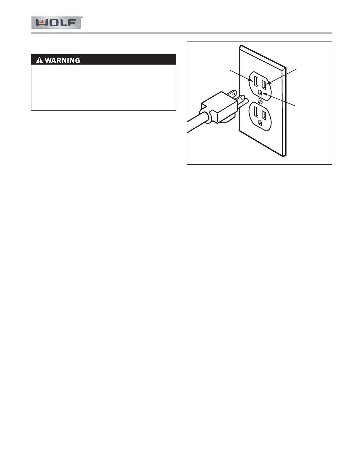
Electrical Requirements
Line
Voltage
(Power)
Neutral
Ground
Figure 3-2. Proper Polarity at Electric Receptacle
ELECTRICAL SHOCK HAZARD: PLUG INTO A
GROUNDED 3-PRONG OUTLET. DO NOT REMOVE
GROUND PLUG. DO NOT REMOVE GROUND
PRONG FROM PLUG. DO NOT USE AN ADAPTER.
FAILURE TO FOLLOW INSTRUCTIONS CAN
RESULT IN SHOCK, FIRE OR DEATH.
A domestic gas range requires a 110-120 V AC, 60 Hz
electrical supply with a 15 amp circuit breaker to oper-
ate the electrical ignition system. A ground circuit inter-
rupter (GFCI) is not recommended and may cause
interruption of operation.
The power supply cord provided with the appliance is
equipped with a 3-prong (grounding) plug. The installa-
tion site must be equipped with a properly grounded 3-
prong receptacle. If the electric receptacle or the power
cord are not properly grounded and polarized, this
could cause a shock hazard and the appliance may
experience ignition problems (See Figure 3-2).
NOTE: Do not ground to a gas pipe.
Gas Range (GR) Series
Gas Range (GR) Series
Installation Information
2-4
#822634 - Revision A - January, 2013
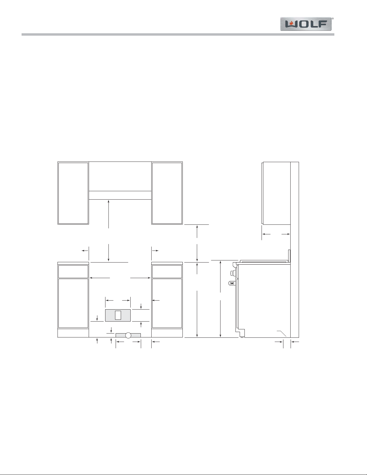
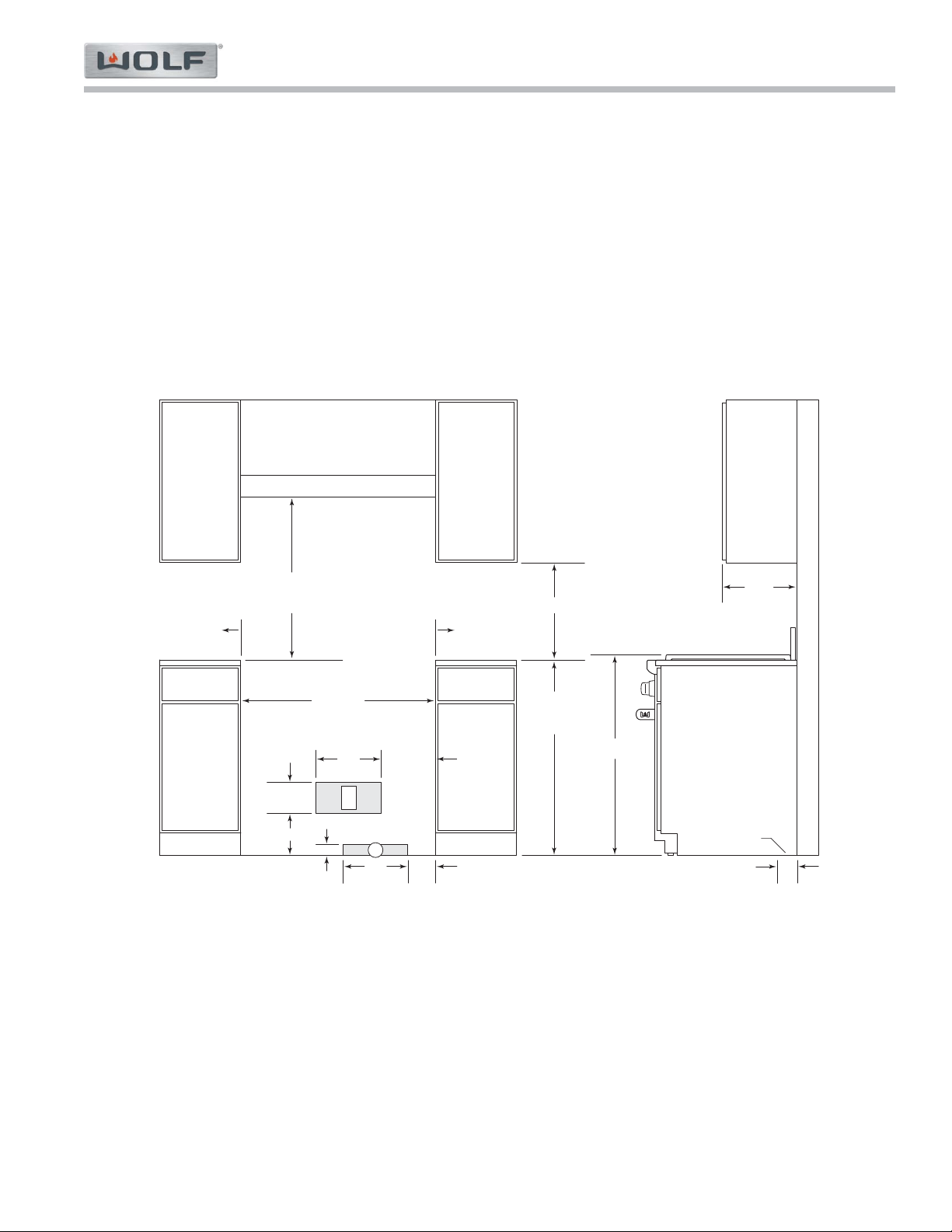
30" (762) Gas Range
INSTALLATION
30" (762)
OPENING WIDTH
30" (762) TO 36" (914)
TO BOTTOM OF
VENTILATION HOOD**
*Min clearance from rough opening to combustible materials up to 18" (457) above countertop.
**42"
(1067) min clearance from countertop to combustible materials without ventilation hood.
NOTE: For island installations, 12"
(305) min clearance from back of range to combustible rear wall above countertop.
6" (152) TO
COMBUSTIBLE*
6" (152) TO
COMBUSTIBLE*
18" (457) min
36" (914)
FLOOR TO
COUNTERTOP
12"
(305)
5"
(127)
G
2" (51)
7
3
/4"
(197)
5
3
/4"
(146)
37" (940)
13" (330)
max
3"
(76)
LOCATION OF GAS AND
ELECTRICAL EXTENDS
ON FLOOR
SIDE
CABINET
E
12"
(305)
10" (254)
Rough-in Installation Specifications
Installation Information
Gas Range (GR) Series
Gas Range (GR) Series
2-5
#822634 - Revision A - January, 2013
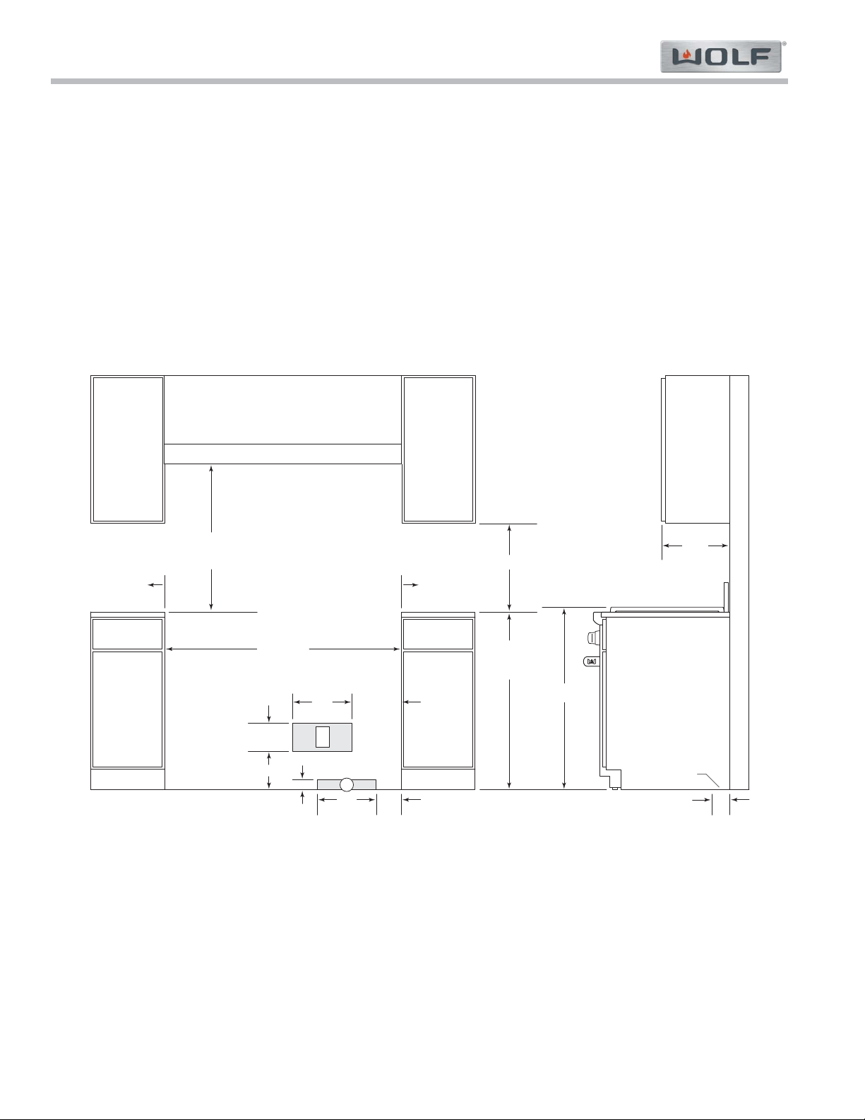
36" (914) Gas Range
INSTALLATION
36" (914)
OPENING WIDTH
30" (762) TO 36" (914)
TO BOTTOM OF
VENTILATION HOOD**
*Min clearance from rough opening to combustible materials up to 18" (457) above countertop.
**42"
(1067) min clearance from countertop to combustible materials without ventilation hood. Charbroiler model requires non-combustible material
above range if installed without ventilation hood.
NOTE: For island installations, 12" (305) min clearance from back of range to combustible rear wall above countertop.
6"
(152)
TO
COMBUSTIBLE*
6"
(152)
TO
COMBUSTIBLE*
18" (457) min
36" (914)
FLOOR TO
COUNTERTOP
12"
(305)
5"
(127)
G
2" (51)
13" (330)
max
3"
(76)
LOCATION OF GAS AND
ELECTRICAL EXTENDS
ON FLOOR
SIDE
CABINET
E
7
3
/4" (197)
5
3
/4"
(146)
12"
(305)
10" (254)
37" (940)
Gas Range (GR) Series
Gas Range (GR) Series
Installation Information
2-6
#822634 - Revision A - January, 2013
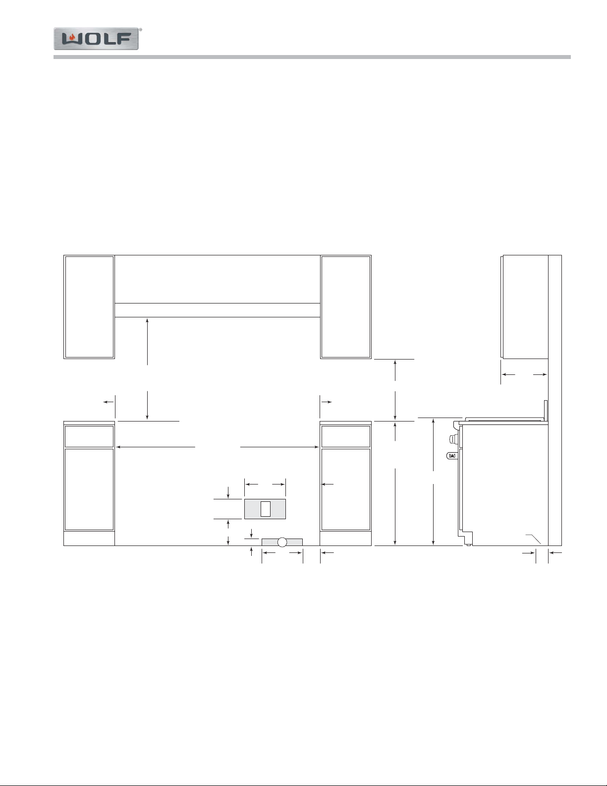
48" (1219) Gas Range
INSTALLATION
48" (1219)
OPENING WIDTH
30" (762) TO 36" (914)
TO BOTTOM OF
VENTILATION HOOD**
*Min clearance from rough opening to combustible materials up to 18" (457) above countertop.
**42"
(1067) min clearance from countertop to combustible materials without ventilation hood. Charbroiler models and GR488 require non-combustible material
above range if installed without ventilation hood.
NOTE: For island installations, 12" (305) min clearance from back of range to combustible rear wall above countertop.
6" (152) TO
COMBUSTIBLE
*
6" (152) TO
COMBUSTIBLE
*
18" (457) min
36" (914)
FLOOR TO
COUNTERTOP
12"
(305)
5"
(127)
G
2" (51)
13" (330)
max
3"
(76)
LOCATION OF GAS AND
ELECTRICAL EXTENDS
ON FLOOR
SIDE
CABINET
E
7
3
/4" (197)
5
3
/4"
(146)
12"
(305)
10" (254)
37" (940)
Installation Information
Gas Range (GR) Series
Gas Range (GR) Series
2-7
#822634 - Revision A - January, 2013
60" (1527) Gas Range
INSTALLATION
60
1
/4" (1530)
OPENING WIDTH
30" (762) TO 36" (914)
TO BOTTOM OF
VENTILATION HOOD
**
*Min clearance from rough opening to combustible materials up to 18" (457) above countertop.
**42"
(1067) min clearance from countertop to combustible materials without ventilation hood. Charbroiler model requires non-combustible material above range
if installed without ventilation hood.
NOTE: For island installations, 12"
(305) min clearance from back of range to combustible rear wall above countertop.
6" (152) TO
COMBUSTIBLE
*
6" (152) TO
COMBUSTIBLE
*
18" (457) min
36" (914)
FLOOR TO
COUNTERTOP
12"
(305)
5"
(127)
G
2" (51)
E
7
3
/4" (197)
5
3
/4"
(146)
12"
(305)
10" (254)
13" (330)
max
3"
(76)
LOCATION OF GAS AND
ELECTRICAL EXTENDS
ON FLOOR
SIDE
CABINET
37" (940)
Gas Range (GR) Series
Gas Range (GR) Series
Installation Information
2-8
#822634 - Revision A - January, 2013
Preparation
Before moving the range, protect any finished flooring
and secure oven door(s) closed to prevent damage.
To lighten the load or to fit through a door way, the oven
door(s) can be removed. Only remove if necessary. Do
not remove griddle or any other component. Door
removal should only be done by a certified installer or
service technician.
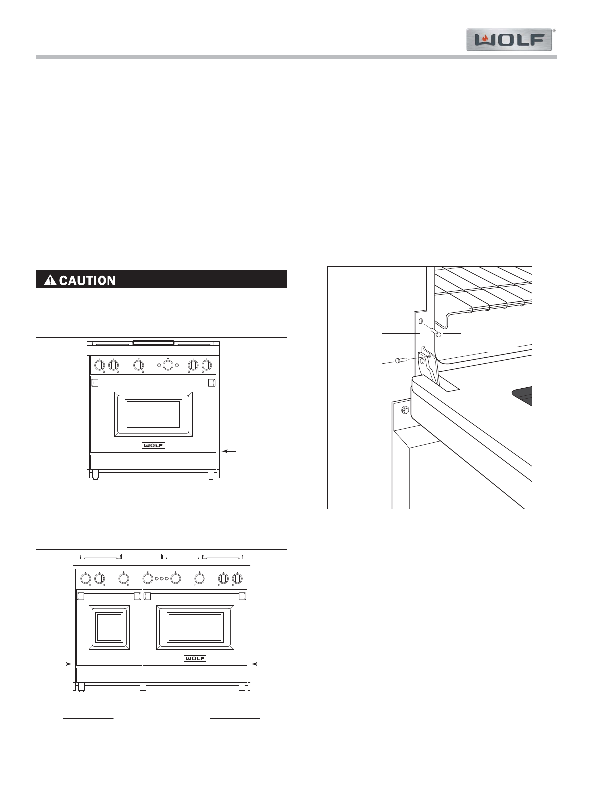
For removal, a hinge pin will be inserted into the appro-
priate hinge shown in Figures 2-3 and 2-4 below. The
pin(s) are located inside the oven door. For single oven
ranges, the hinge pin must be inserted in the right
hinge. For double oven ranges, the pins must be placed
in the outer two hinges.
Failure to insert the hinge pin in the appropriate
hinge arm will cause damage to the range.
SPRING HINGE
Figure 2-3. Single Oven Ranges (30” & 36”)
SPRING HINGES
Figure 2-4. Double Oven Ranges (48” & 60”)
Oven Door removal (See Figure 2-5)
1. Insert the hinge pin into the appropriate hinge.
2. Remove the lower kickplate assembly to access the
lower hinge retainer mounting screws.
3. Open the oven door and remove both upper and
lower hinge retainer mounting screws. The oven
gasket may have to be moved slightly to access the
bottom screws.
4. Move the hinge retainer plate forward slightly. The
hinge retainer plate will remain on the door hinge
after the mounting screws have been removed.
5. Carefully close the oven door to approximately 60°,
then lift the door up and out. A slight rocking
motion may be required for removal.
KICKPLATE
UPPER
MOUNTING
SCREW
HINGE
RETAINER
PLATE
HINGE
PIN
Figure 2-5. Oven Door Removal (18”)
Installation Information
Gas Range (GR) Series
Gas Range (GR) Series
2-9
#822634 - Revision A - January, 2013
Placement
Do not lift or carry the oven door by the door handle.
The range has rear casters which allow for easy move-
ment by lifting the front of the unit.
Use an appliance dolly to move the unit near the open-
ing. Remove and recycle packing materials. Do not dis-
card the anti-tip bracket supplied with the range.
If a riser has been specified, refer to the installation
instructions packaged with the riser. The riser must be
installed before the range is installed.
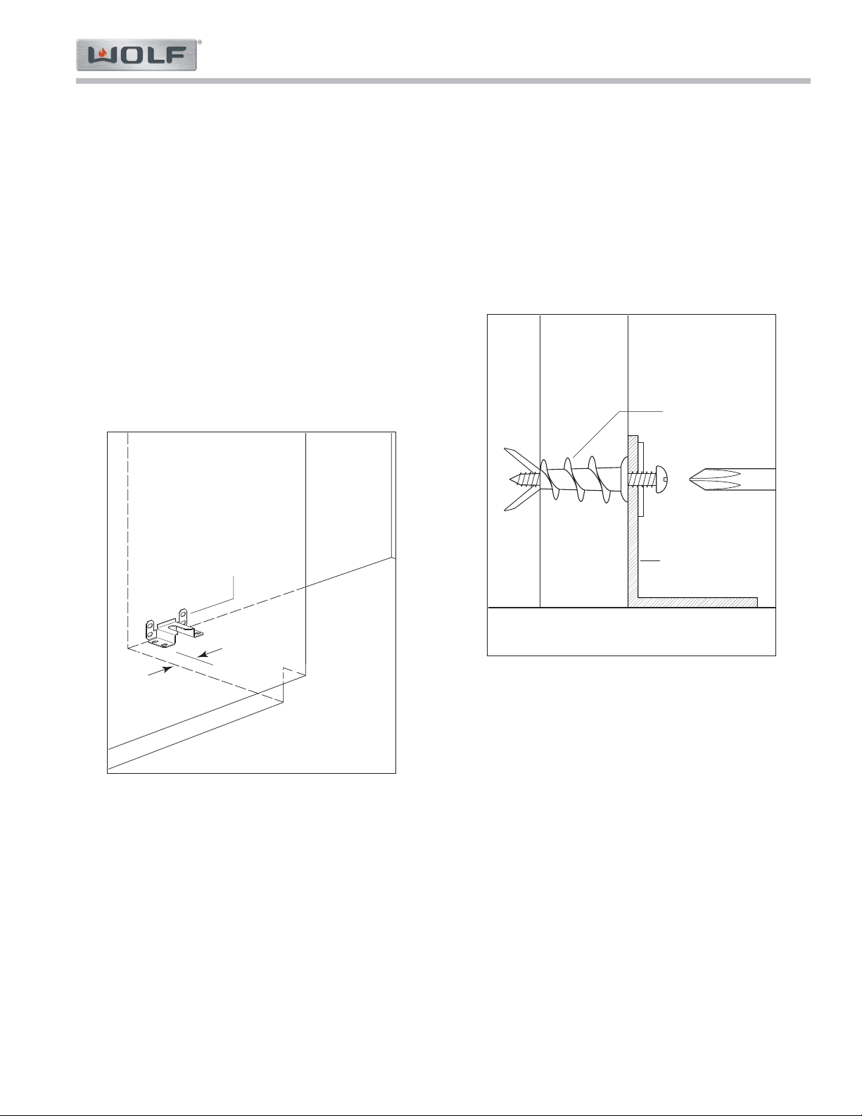
Anti-Tip Bracket
To ensure the anti-tip bolt engages the bracket, position
the bracket 3" (76) from the left side of the opening.
Refer to Figure 2-6.
3" (76)
ANTI-TIP
BRACKET
Figure 2-6. Anti-Tip Bracket Location
Anti-Tip Bracket Installation
Drywall Application
After properly positioning the anti-tip bracket, mark
holes, then use a Philips screwdriver or a low rpm
power drill to drive the wall anchor into the surface of
the wallboard until flush. Pre-drill holes if needed. For
hard wallboard or double-board construction, use a 1/4”
drill bit. For solid plaster, use a 7/16” drill bit. Refer to
Figure 2-7. Use #8 screws and flat washers to fasten
the bracket to the wall.
ANTI-TIP
BRACKET
WALL
ANCHOR
Figure 2-7. Anti-Tip Drywall Application
Wood Floor Application
After properly positioning the anti-tip bracket, drill 3/16”
(5) pilot holes through the floor. Use #12 screws and
flat washers to secure the bracket to the floor.
Concrete Floor Application
After properly positioning the anti-tip bracket, drill 3/8”
(10) holes into the concrete a minimum of 1-1/2’ (38)
deep. Use 3/8” wedge anchors to secure the bracket to
the floor.
Gas Range (GR) Series
Gas Range (GR) Series
Installation Information
2-10
#822634 - Revision A - January, 2013
• A CHILD OR ADULT CAN TIP THIS APPLIANCE
AND BE KILLED.
• VERIFY THE ANTI-TIP DEVICE HAS BEEN
PROPERLY INSTALLED AND ENGAGED.
ENSURE THE ANTI-TIP DEVICE IS RE-
ENGAGED WHEN THIS APPLIANCE IS MOVED.
REFER TO THE ILLUSTRATIONS ON THIS AND
THE PREVIOUS PAGE FOR HOW TO VERIFY
CORRECT INSTALLATION.
• TO REDUCE THE RISK OF BURNS, DO NOT
MOVE THIS APPLIANCE WHILE HOT.
• DO NOT OPERATE THIS APPLIANCE WITHOUT
THE ANTI-TIP DEVICE IN PLACE AND
ENGAGED. FAILURE TO DO SO CAN RESULT IN
DEATH OR SERIOUS BURNS TO CHILDREN OR
ADULTS.
Leveling the Range
Raise the unit to the desired height by adjusting the
front legs and rear casters. The front legs can be
adjusted by rotating the hexagonal leg clockwise to
raise and counterclockwise to lower. The rear casters
(wheel assemblies) can be adjusted by rotating them
clockwise to raise and counterclockwise to lower. For
fine adjustments of the rear wheel assembly, a long
sturdy screwdriver or bar can be used when the appli-
ance is in place by inserting the tool between the wheel
brackets and spinning the rear wheel assembly with the
tool as needed.
NOTE: If necessary, perform pre-leveling of the range
before pushing it into its installation, with fine adjust-
ments made after the appliance is installed.
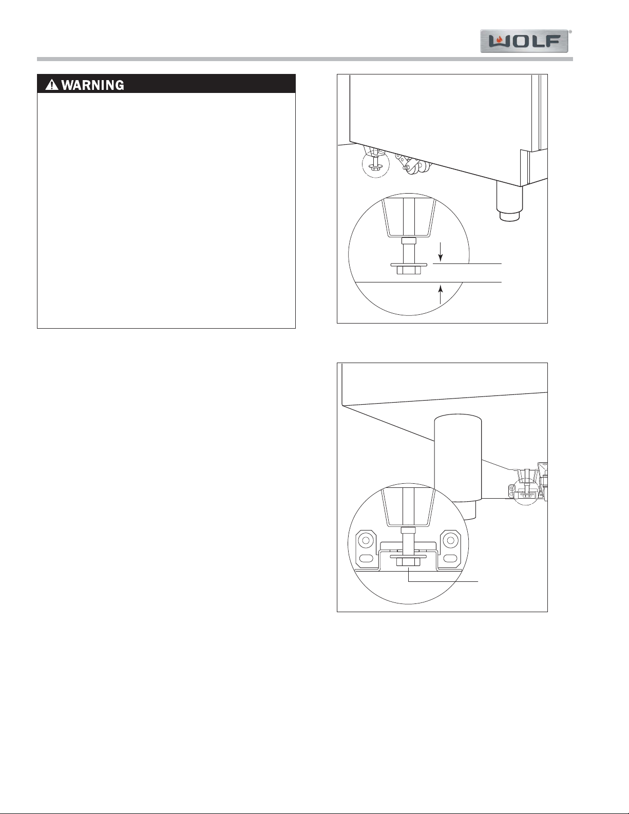
Anti-Tip Bolt Adjustment
Once the anti-tip bracket is secure and the appliance is
installed and leveled, adjust the anti-tip bolt so the top
of the washer is 7/8” (22) maximum from the floor.
Slide the range into the opening and verify the anti-tip
bolt is engaged. Refer to Figures 2-8 and 2-9.
7
/8" (22) MAX
ANTI-TIP
BOLT
Figure 2-8. Anti-Tip Bolt
ANTI-TIP
DEVICE
ENGAGED
Figure 2-9. Anti-Tip Device and Bolt Engaged

Gas Range (GR) Series
Gas Range (GR) Series
Theory of Operation
3-2
#822634 - Revision A - January, 2013
THEORY OF OPERATION
A service technician should understand how a gas appliance operates before attempting to service the appliance.
This section provides descriptions of the different types of fuel gases and explains gas heating values. A definition
of specific gravity of gas is given along with its characteristics and effects. Gas combustion principals are explained
and gas burner components are described and illustrated. The end of this section contains illustrations which
demonstrate basic cooking appliance theory of operation.
Types of Fuel Gas:
Gases used to supply heat energy are called fuel gases. Common fuel gases are not simply one kind of hydrocar-
bon, they are mixtures of hydrocarbon gases. They contain other gases as well, such as free hydrogen, carbon
dioxide and nitrogen. As an example natural gas might contain 85% methane, 12% ethane and 3% of other gases.
The presence of each of these gases in the fuel gas has some effect on the nature of the gas.
Some common fuel gasses are methane [CH4], ethane [C2H6], Propane [C3H8] and butane [C4H10]. Propane and
butane are nearly odorless. Natural gas that is processed to remove condensables and moisture, has little or no
odor and no color. Odorants are added to natural gas before distribution to aid in leak detection. A common odorant
used is a colorless liquid containing sulfur compounds.
Heating Value of Gas:
Heat energy produced when burning a fuel gas is commonly expressed in British Thermal Units (BTU). One BTU of
heat will raise the temperature of one pound of water one degree Fahrenheit.
The more carbon and hydrogen atoms in each molecule of a fuel gas, the higher its heating value. Natural gas
which is high in methane has a heating value of about 950 to 1150 BTU per cubic foot. The variance is due to the
various other substances found in natural gases. The more ethane, propane or butane in the gas raises the heating
value. Propane, or LP gas, has a heating value of about 2500 BTU per cubic foot, and butane about 3200 BTU per
cubic foot.
Specific Gravity of Gas:
The specific gravity of a gas is the weight of one cubic foot, or the gas compared to one cubic foot of dry air. When
stating the specific gravity of a gas, a pressure and temperature must be clearly stated. In the gas industry, the
standard conditions of pressure and temperature are 30.0 inches of mercury and 60° F. A pressure of 30.0 inches of
mercury will sustain a column of mercury 30 inches high in a tube with a vacuum on top of the column. Since air is
used as the reference, its specific gravity is always 1.0. This value of 1.0 has no direct physical meaning with
regard to air, such as its density. It is only a relative number or ratio used to express specific gravity of other gases.
The specific gravity of a gas will determine if the gas will rise or fall when released into the air. Natural gas will rise
since its specific gravity is less than 1.0 at 0.4 to 0.8. Propane has a specific gravity of 1.5 and butane 2.0. These
gases will fall when released into the air. They sometimes collect in low spots into pools which become a hazard if
open flames are present.
In addition, specific gravity has two other characteristics. It has an important effect on the flow of gases through ori-
fices, and hence the rating of the burners. Gas flow through an orifice is dependent upon the orifice size and the
gas pressure upstream of the orifice. More of a lighter gas will flow through a given orifice size than a heavier gas
at the same gas pressure. This effect is taken into account in tables and calculators used to select orifice sizes for
burners.
The gas flow in pipes is also affected by specific gravity. At a given pressure at a pipe inlet, more lighter gas will
flow through a pipe than a heavier gas.

Theory of Operation
Gas Range (GR) Series
Gas Range (GR) Series
3-3
#822634 - Revision A - January, 2013
Principals of Gas Combustion:
Combustion
When oxygen acts with a substance to produce large amounts of heat rapidly.
Requirements for Combustion
There are three required elements for combustion to occur; Fuel (Gas), Oxygen (Air) and Heat (Ignition
Temperature, which for gas is between 1100°F/593°C and 1200°F/649°C). All must be present. Removing any one
of the three and combustion will cease.
Chemistry of Combustion
Combustion of gas is a chemical reaction between fuel gas and oxygen. The basic elements of common fuel
gasses are hydrogen [H] and carbon [C]. When hydrogen burns, water vapor [H2O] is produced. Complete burning
of carbon in fuel gases form carbon dioxide [CO2] and water vapor [H2O].
Controlled Combustion
Controlled combustion takes place when gas and air are supplied at proper rates to assure complete combustion of
the gas in a steady flame. When a gas appliance is operating properly, burning starts at the burner ports. Gas flow
is controlled by gas orifice size and gas pressure upstream of the orifice. Air is mixed with the gas before it passes
through the burner ports. This added air is called “Primary Air”. The remaining air required for complete combustion
is supplied to the burner at the point of combustion and is called “Secondary air”.
Adjustments of the gas-to-air ratio and the secondary air supply is the key to obtaining stable blue flames at a burn-
er. Proper amounts of primary and secondary air are required for quiet and efficient burner operation and for com-
plete combustion of the gas. Air Shutters or other devices provide control of primary air. Inlet opening and flue out-
lets control Secondary Air flow.
Total air
In an ideal situation, primary and secondary air is all that is needed (for the oxygen required) to burn the gas, but
some additional air is required to assure complete burning of the gas. The total air, “primary”, “secondary” and
“excess” are expressed as percentages of the amount needed. About ten cubic feet of air is required to completely
burn one cubic foot of gas. For this reason an appliance should not be operated in an air tight home.
Limits of Flammability
Not all air-to-gas mixtures will burn. Mixtures with 0% - 4% natural gas in air are too lean to burn. Mixtures of 4% -
14% natural gas in air can burn with a controlled flame. Flammability limits come into play when primary air adjust-
ments are made on burners. If too much primary air is used, the mixture may become too lean and fall below flam-
mability limits, thus preventing combustion.
Incomplete Combustion (Causes and Effects)
To obtain complete combustion, sufficient amounts of air must be supplied to the process. This air must have a rea-
sonably normal oxygen content. Complete burning of gas produces harmless carbon dioxide gas and water vapor.
If the air supply is insufficient, incomplete combustion occurs resulting in the formation of toxic by-products, such as
carbon monoxide [CO] or aldehydes.
Carbon monoxide is colorless and odorless. Inhaling carbon monoxide in sufficient quantities could cause death by
reducing oxygen levels in the blood.
Aldehydes, which are equally dangerous, have a sharp and penetrating odor which is easily detected by smell at
very low concentrations. The odor caused by aldehydes should not be confused with odorants added to natural gas.
The absence of aldehydes does not assure that carbon monoxide is not present. However, if the odor of aldehydes
is present, then carbon monoxide is virtually always present.
Gas Burner Operation
A gas burner is a device to burn gas under control in order to produce useful heat. Primary air is brought into the
burner from outside of the appliance at atmospheric pressure. The gas jet streaming from the orifice draws primary
air with it into the burner.
The gas/air mixture, combined with a spark at the burner port(s) and the secondary air creates a controlled burn.
Gas Range (GR) Series
Gas Range (GR) Series
Theory of Operation
3-4
#822634 - Revision A - January, 2013
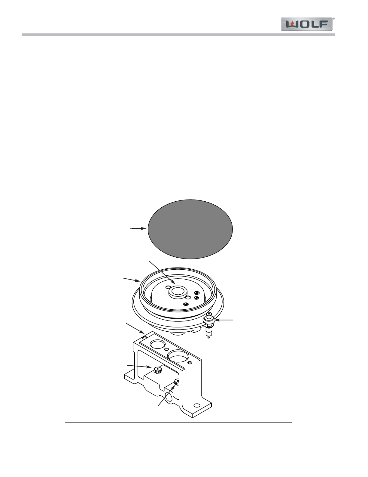
Figure 3-1. Burner Components
Electrode
Burner
Burner Cap
Orifice Holder
Simmer Orifice
Main Orifice
Venturi
Surface Burner Components (Refer to Figure 3-1 below):
Burner Cap - Provides the upper portion of the ports required to create a combustible mix and proper flame quality
of the burner and the decorative top for the burner with a black porcelain coating.
Burner - Contains the burner ports where the gas/air mixture ignites. The burner ports are distributed in a useful
pattern to optimize heat transfer. The flames should be spread so they can be easily reached by secondary air and
provide a stable blue flame. The burner also incorporates the Inner Distribution Ring, which Routes the gas from the
simmer orifice to the simmer port holes, and the Outer Distribution Ring, which routes the gas from the main burner
orifice to the main burner port holes.
Venturi - Helps maintain proper and constant primary air injection.
Electrode - The Electrode supplies the spark to ignite the burner. The electrode senses the flame, once the burner
is ignited and will stop sparking. If no flame is sensed, and the valve is opened, the electrode will start sparking to
re-ignite the flame. This is part of the auto-reignition system.
Orifice Holder - This component is mounted to the burner mounting bracket and to the burner box. The Simmer
and Main orifice is threaded into the orifice holder and routes the gas to the appropriate ports of the burner. It is the
main support for the burner components.
Simmer Orifice and Main Orifice - An opening or hole which regulates or limits the amount of gas flowing to a
burner. Gas flow rate (volume) depends on the size of the orifice (hole) and the gas pressure at the inlet of the ori-
fice.
Theory of Operation
Gas Range (GR) Series
Gas Range (GR) Series
3-5
#822634 - Revision A - January, 2013
Other Types of Burners:
Blue Flame Burners
All surface burners, including the French Top burners are blue flame burners. With this type of burner, primary air is
mixed with the fuel gas before the gas reaches the burner ports. An orifice is used to regulate gas flow to the burn-
er and is sized to draw exact amount of air into the burner body. Air, which is mixed with the gas inside the burner
body then exits the burner ports located in the burner head, where it is ignited. Secondary air is air from around the
flames. The flame produced has several zones, each represents a stage in burning of the gas. The burner tip has a
thin dark blue cone called the inner or primary cone. A lighter cone called the outer cone, surrounds the inner cone.
Air around the flame diffuses into the flame to burn at the outer cone. If conditions are perfect, products from the
inner cone burn here. The final products of burning are carbon dioxide and water vapor. An outer mantle surrounds
the outer cone where burning is usually completed. It is nearly invisible and glows only because of the high temper-
ature of the final combustion.
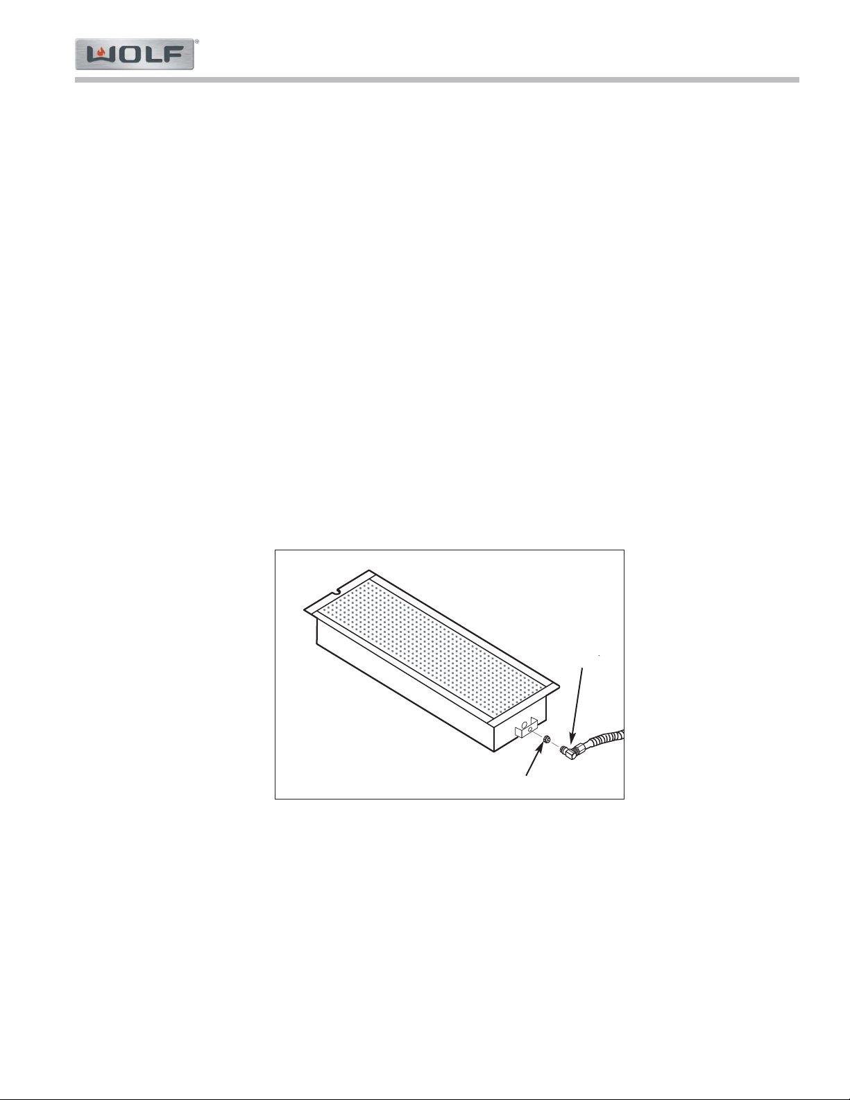
Infrared Burners
Wolf Sealed Rangetops also use infrared burners. The under-fired application for the charbroiler and the griddle
uses a porous refractory ceramic tile burner (See Figure 3-2). With this type of burner, a substantial amount of
energy output is in the form of infrared radiant energy. With infrared heat, thermal energy is transmitted through
space without heating the medium through which it travels. Infrared energy is usually not affected by air flowing
between the burners and heated surfaces because of the burner’s numerous and tiny flames. This type of heat is
very efficient and compact. The under-fired refractory infrared burner requires 100 percent primary air and is
designed to have a hot glowing burner surface. The flame burns close to the burner surface at a high temperature.
NOTE: There is no shutter on infrared burners for adjusting the primary air and there is no change in orifice size for
different altitude.
Figure 3-2. Infrared Burner
Charbroiler and Griddle Orifice
Gas Orifice
Elbow
DSI Board Operation (Griddle / French Top / 18” Oven only)
The DSI board serves the purpose of igniting the griddle burner, detecting the presence of this flame, and provides
the signal to open the gas valve. When the thermostat is turned on, the red (call for heat) light comes on and the
gas solenoid is opened. At this time you will hear a series of sparks and it will begin to check for the presence of a
flame. If the igniter probe does not detect flame within a short period of time, the gas valve solenoid shuts off and
there will be a delay before trying to reignite (this allows time for the non-combusted gas to dissipate). This process
will reoccur in three sets and if it fails a third time the DSI board will shut down and will wait for the thermostat to be
turned off and on before attempting to reignite. If flame detection is lost during operation this board will also allow
time for the non-combusted gas to dissipate, and will attempt to reignite after this delay.
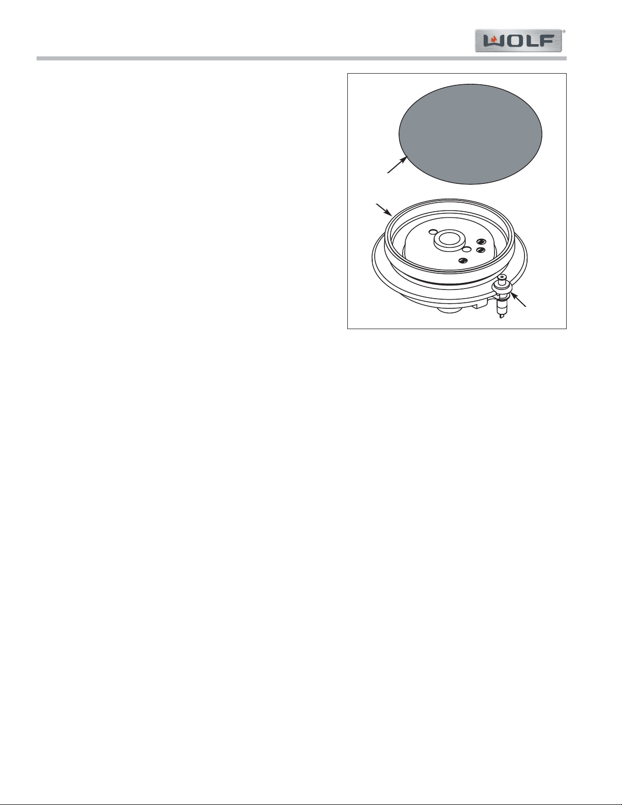
After removing burner parts for any reason, it is extremely impor-
tant that the burners are re-assembled correctly. The burner cap
has a special orientation and should be seated flatly (See Figure
3-3).
This patented dual stacked burner configuration makes it possible to enjoy cooking at full flame as well as maintain-
ing control while simmering at the lowest flame setting.
Gas Range (GR) Series
Gas Range (GR) Series
Theory of Operation
3-6
#822634 - Revision A - January, 2013
Grate Placement
Low profile cast iron grates are designed for a close fit. This enables pans to move easily from one burner to anoth-
er without having to lift the pan or have it tip over between the grates. Each grate sets securely on dimples on each
corner of the cooktop pan. Continuous grates are interchangeable.
Control Knobs
The control knobs are positioned to correspond to the burners they regulate. The knobs on the far left regulate the
burners on the left side. Conversely, the knobs on the far right regulate the burners on the right side.
Burner Lighting
To light a burner push in and turn the corresponding control knob counter clockwise to the HIGH setting. You will
hear “clicking” and see the burner ignite. Once the burner is lit, continue turning the knob counter clockwise to any
setting, HIGH through LOW.
To select a simmer setting, turn the knob to the LOW setting. You will feel a stop-detente in the knob rotation. Push
in on the knob, continuing to turn it counter clockwise. This moves the flame to the second tier. Now, select any
variation within the SIMMER flame settings, HIGH through LOW.
Each knob is designed to be a “push-to-turn knob”. Although this is a child-safe design, children should never be left
unattended in the kitchen when the range is in use.
Power Outage (Domestic Units Only)
In case of a power outage, the surface burners can be re-lit manually. Turn the control knob to “high” and place a
flame near the igniter to light the burner.
Figure 3-3. Stacked Dual Burner Assembly
Electrode
Burner
Burner Cap
OPERATION OF GAS RANGE SURFACE BURNERS
Surface Burners
A spark electrode ignites each surface burner. This control elimi-
nates the need for continuous open flame pilots. For added safe-
ty and convenience, each burner is designed with an electronic
re-ignition system. This feature enables any burner to automati-
cally re-light in the event it is accidentally extinguished.
This unique dual stacked burner design combines all the burner
parts in one configuration. Large burners provide a Btu/hr rating
of 15,000 on HIGH and a High Simmer Btu/hr rating of approxi-
mately 3300. Small burners provide a Btu/hr rating of 9,200 on
HIGH and a High Simmer Btu/hr rating of approximately 1600. All
burners have simmer settings.
A distinguishing feature of the Wolf low Btu/hr control is its con-
stant, low heat output without continuous ignitions. Flame
diameter remains full size, only the heat output is lowered. This is
the ultimate control for simmering food.

Theory of Operation
Gas Range (GR) Series
Gas Range (GR) Series
3-7
#822634 - Revision A - January, 2013
Charbroiler
This optional feature is designed with an infrared burner to give the highest quality and most efficient method of gas
grilling. These burners become an orange-red color at the surface of the ceramic tiles. When the tiles are glowing,
they transfer an intense heat to the food being grilled. This chars the outside of the food and leaves the inside ten-
der and juicy.
The infrared burner is designed to operate at a full heat output of 16,000 BTU/hr. It is recommended using the Wolf
blank-off plate when grilling most foods.
Charbroiler Operation
• Turn on the ventilation hood prior to using the charbroiler.
• If the knob is not set fully at "HIGH", the burner may turn blue and the automatic igniter will begin sparking. Turn
the knob back to "HIGH".
• Preheat grill for about ten minutes before adding the food. The tiles will have an orange glow.
• For the 22-inch charbroiler, there are two separate burners with separate control knobs, which act independently
of each other.
Gas Range (GR) Series
Gas Range (GR) Series
Theory of Operation
3-8
#822634 - Revision A - January, 2013
Burner Pan
Although resistant to most
stains, it is not totally impervi-
ous to damage. Salt and
some cooking liquids may pit
and stain surface. Always
remove these spills immedi-
ately.
Avoid using abrasive cleaners;
they will permanently scratch
the surface.
Burner Cap
Burner Grates
Control Knobs
Spark Igniters
Part Identification Material Care Recommendation
Exterior Finish Porcelain Steel
Porcelain Enamel
(matte finish)
Never wipe a warm or hot
porcelain surface with a damp
sponge; it may cause chipping
or crazing (tiny hair-like
cracks)
Porcelain-Coated Cast Iron
Metal
Ceramic
General care: Use a clean cloth or sponge, wipe
with warm water and mild detergent. Rinse and
dry immediately. Apply protective polish, always in
the same direction.
Spray degreaser: Removes fingerprints and
greasy spatters. Spray on a cloth and wipe sur-
face. Buff dry immediately to avoid streaking.
Protective polish: Apply to surface to maintain
luster and protect from some food stains
Hard water stains: Use white vinegar and water.
Cool first. Wash in warm water with liquid deter-
gent or mild abrasive cleaners.
Foods high in acid or sugar content, such as milk,
tomatoes, sauerkraut, fruit juices and pie filling,
may pit or craze the surface. Remove as soon as
possible. Do not cook the spill on again.
Remove from cooktop and place on a flat surface
near the sink.
Non-abrasive cleaners: Hot water and liquid
detergent, paste of baking soda and water, plastic
pad or sponge.
Mild abrasive and abrasive cleaners: Use spar-
ingly.
General care: Wipe each knob with a damp cloth
and mild soap and water; rinse and dry. Never
soak or use abrasive cleaners; they will scratch
the finish and remove the markings.
Keep dry. Never spray water or cleaner directly on
the igniter. When cleaning around the surface
burner, be careful that the cloth does not catch on
the igniter and damage it.
Cleaning and Maintenance of Surface Burner Components
Theory of Operation
Gas Range (GR) Series
Gas Range (GR) Series
3-9
#822634 - Revision A - January, 2013
Blank-Off Plate (If Applicable)
Charbroiler Frame
Grate
Igniter
Radiant Plate
Part Identification Material Care Recommendation
Stainless Steel
Stainless Steel
Porcelain Coated Cast Iron
Ceramic
Stainless Steel
Wash with hot water and detergent. Use a soap-
filled scouring pad to remove as much cooked-on
soil as possible. The plate will turn a metallic blue
color due to high heat; this is a permanent change.
Remove from the range. Soak in hot water and
dish detergent. Wash thoroughly, scrubbing with
scouring pad, if needed. Rinse and dry.
When cool, lift off and set in the sink. Pour very
hot water over the cooked-on residue. Cover with
wet dish towels and pour more hot water over it.
Allow the hot, moist conditions time to help loosen
the residue. Remove remaining soil with a soap-
filled scouring pad. Rinse and dry.
Avoid contact with the igniter; it is fragile and can
chip or break.
Remove from the range. Soak in hot water and
dish detergent. Wash thoroughly, scrubbing with
scouring pad, if needed. Rinse and dry.
Charbroiler Cleaning and Maintenance
Griddle
The cast iron griddle plate operates at 18,000 Btu/hr. It is thermostatically, controlled which means once the set
temperature is reached, the heat cycles to hold that setting. Prior to use it is necessary to "season" the griddle to
protect the surface from moisture. This process will change the appearance.
NOTE: Seasoning does not create a non-stick surface. The use of additional oil is necessary during cooking.
Griddle Operation
• To heat the griddle, push in the knob and turn counter clockwise to desired temperature. It is normal to hear a
clicking sound. This is the electronic ignition lighting the burner. When the burner is lighted, the thermostat will
control the temperature.
• Preheat for approximately 10 to 15 minutes. When the griddle is preheated, the griddle indicator light will go out.
The light will cycle on and off as the thermostat needs more heat to maintain the set temperature. This will allow
heat to be evenly distributed and reach the set temperature.
• For the 22-inch griddle, there are two separate burners with separate control knobs, which act independently of
each other.
• To turn off the griddle, turn the knob clockwise to the "OFF" position.
Griddle Care
• Use a metal spatula and scrape grease into the grease collection tray.
• When the surface has cooled, wipe it with a paper towel to remove excess grease or oil.
• Clean grease collection tray after each use. Do not allow grease to accumulate in the tray and become a fire
hazard.
• To remove the drip tray, gently pull the tray towards yourself to lift it out. Clean drip tray with soapy water and a
clean cloth.

Gas Range (GR) Series
Gas Range (GR) Series
Theory of Operation
3-10
#822634 - Revision A - January, 2013
Oven Burner Components
Blue Flame Oven Bake Burner Components:
Gas Orifice - An opening or hole which regulates or limits the amount of gas flowing to a burner. Gas flow rate (vol-
ume) depends on the size of the orifice (hole) and the gas pressure at the inlet of the orifice.
Air Shutter - This is used to adjust the size of the primary air inlet area and therefore controls primary air flow.
Venturi Tube - A section of pipe at the inlet of the burner body that narrows and then flares out again. This tube
helps maintain a proper and constant primary air injection.
Mixing Tube/Throat - Serves to carry the gas/air mixture from the venturi tube to the burner tube.
Burner Tube - The U-shaped tube containing the burner ports where the gas/air mixture ignites. The burner ports
are distributed in a useful pattern to optimize heat transfer. The flames should be spread so they can be easily
reached by secondary air and provide a stable blue flame.
Electrode - The Electrode supplies the spark to ignite the burner. The electrode senses the flame, once the burner
is ignited and will stop sparking. If no flame is sensed, and the valve is opened, the electrode will start sparking to
re-ignite the flame. This is part of the auto-reignition system.
Infrared Oven Broil Burner Components:
Gas Orifice - An opening or hole which regulates or limits the amount of gas flowing to a burner. Gas flow rate (vol-
ume) depends on the size of the orifice (hole) and the gas pressure at the inlet of the orifice.
Venturi Tube - A section of pipe at the inlet of the burner box that narrows and then flares out again. This tube helps
maintain a proper and constant primary air injection.
Mixing Tube/Throat - Serves to carry the gas/air mixture from the venturi tube to the infrared burner box.
Burner Box - The box in the ceiling of the oven with wire mesh on its lower surface that catches the gas/air mixture
allowing from the mixing tube it to gather.
Electrode - The Electrode supplies the spark to ignite the burner. The electrode senses the flame, once the burner
is ignited and will stop sparking. If no flame is sensed, and the valve is opened, the electrode will start sparking to
re-ignite the flame. This is part of the auto-reignition system.
DSI Board Operation (30”, 36” Ovens only)
The DSI detects flame as any other spark module we offer with re-ignition. The flame from the burner produces a
small electrical current that the spark electrode can sense by being in the flame. If a current is detected, the elec-
tronics can adjust spark occurrence or trigger things to happen such as a gas valve. Once the DSI is energized, or
the oven has a call for heat. The following sequence takes place:
• DSI will send 10V to the gas valve to open and allow gas to flow to the burner.
• Sparking starts and continues for 7 seconds or until a flame is detected as mentioned above.
• If no flame is detected, the DSI triggers the gas valve to close, stops sparking, and waits 40 seconds to purge
the gas from the oven.
• DSI will open the gas valve again.
• Sparking will continue for 7 seconds or until flame is detected.
• If no flame is detected again, the system will shut the gas valve, stop sparking and wait 40 seconds for gas
purge.
• If no ignition after this second cycle, the LED oven light will blink showing an issue.
NOTE: If the oven is physically turned off during that 40 second gas purge, the oven will reset that 40 second count
before allowing spark and gas flow. If after 40 seconds, the cycle can be repeated if the oven is turned off, then
back on.
Gas Range (GR) Series
Gas Range (GR) Series
Component Access & Removal
4-2
#822634 - Revision A - January, 2013
COMPONENT ACCESS AND REMOVAL
This section explains how to access and remove components from a Gas Range.
NOTE: Before attempting to access or remove any components from a Wolf appliance, take note of WARNINGS
and CAUTIONS below.
• TO AVOID SERIOUS BURNS AND/OR EXPLOSIONS, KEEP COMBUSTIBLES AWAY FROM THE APPLIANCE
WHENEVER A FLAME IS PRESENT.
• KEEP IN MIND THAT OVEN SURFACES AND COMPONENTS GET HOT DURING USE OF THE APPLIANCE.
IF THE OVEN IS SWITCHED ON DURING SERVICE, KEEP YOUR FACE AWAY FROM THE DOOR WHEN
OPENING IT.
• TO AVOID GAS LEAKS, THE GAS SUPPLY TO APPLIANCE MUST BE SWITCHED OFF BEFORE DISCON-
NECTING ANY GAS LINES ON OR TO THE APPLIANCE.
• TO AVOID ELECTRIC SHOCK, POWER TO UNIT MUST BE DISCONNECTED WHENEVER ACCESSING
AND/OR REMOVING COMPONENTS POWERED BY ELECTRICITY OR COMPONENTS NEAR OTHER ELEC-
TRICAL COMPONENTS.
• IF IT IS NECESSARY TO REMOVE A UNIT FROM ITS INSTALLATION, REMEMBER THAT UNIT COULD TIP
FORWARD WHEN PULLED BEYOND THE ANTI-TIP COMPONENTS, RESULTING IN SERIOUS INJURY OR
DEATH. PULLING A UNIT FROM ITS INSTALLATION SHOULD ONLY BE PERFORMED BY AN AUTHORIZED
SERVICE TECHNICIAN OR INSTALLER.
• WHEN REASSEMBLING GAS SUPPLY LINE TO REGULATOR, ONLY PIPE THREAD COMPOUND SHOULD
BE USED. DO NOT USE TEFLON TAPE TO SEAL GAS PIPE CONNECTIONS.
• WHEN REASSEMBLING REGULATOR TO MANIFOLD, ONLY PIPE THREAD COMPOUND SHOULD BE USED.
DO NOT USE TEFLON TAPE TO SEAL GAS PIPE CONNECTIONS.
If removing a door or disconnecting the door spring, remember the spring could recoil quickly when
released. Keep hands away from the connecting bracket.
Component Access & Removal
Gas Range (GR) Series
Gas Range (GR) Series
4-3
#822634 - Revision A - January, 2013
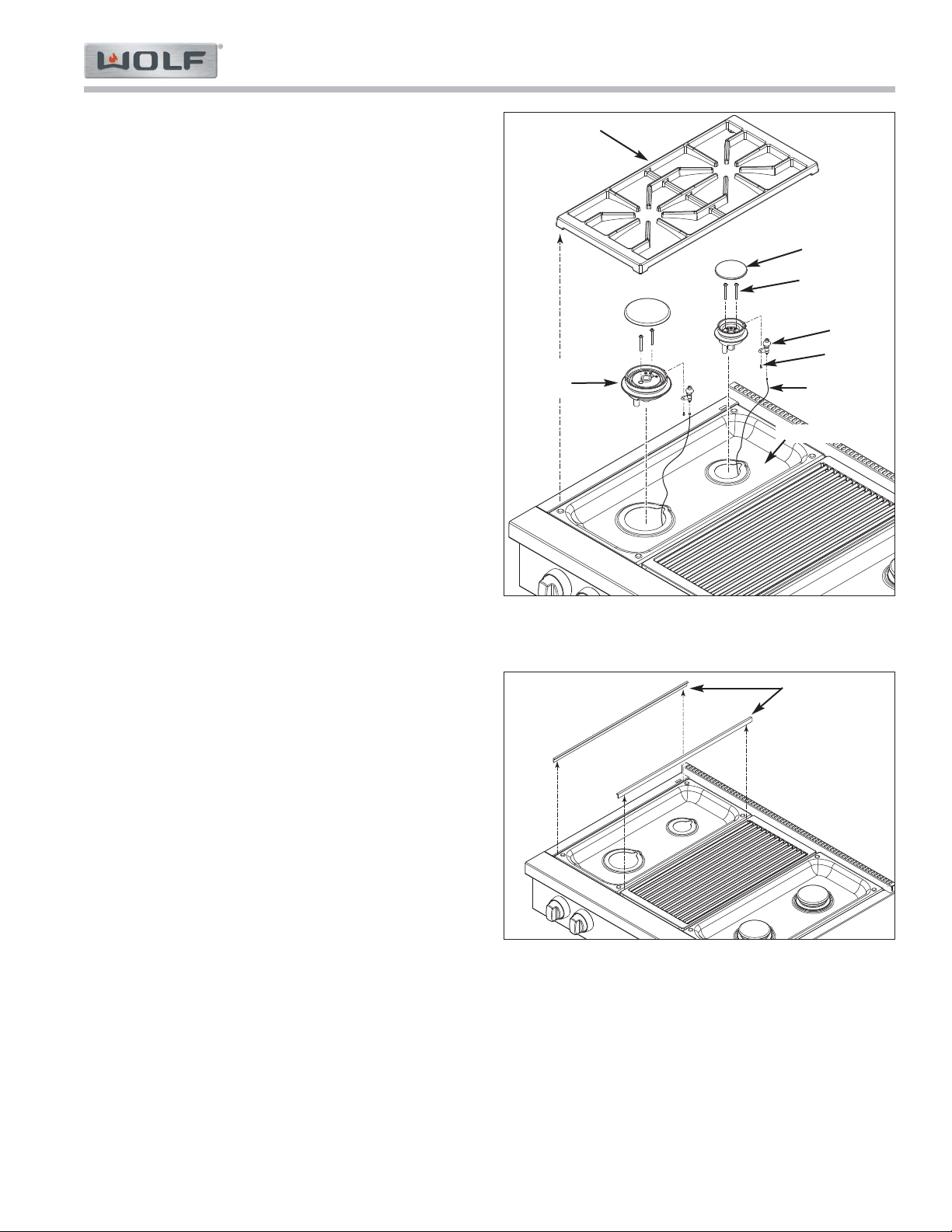
Surface Burner Components:
Burner Grate and Burner Assembly
The burner grates have pockets at each corner with
rubber grommets in them. the grates are located into
proper position by the rubber grommets fitting over
raised dimples formed on the burner pan.
A burner cap set on top of the burner body. Below the
cap screws pass through the burner body and then
thread into the orifice holder.
To remove the burner assembly (See Figure 4-1):
1. Lift the burner grate from burner pan.
2. Lift burner caps from burner head assembly.
3. Extract the two screws securing burner head
assembly to orifice holder.
4. Lift assembly off burner pan and disconnect wire
lead from spark ignitor.
5. To remove spark ignitor from burner, extract screw
from underside of burner assembly and separate.
NOTE: For service, the spark igniter is supplied
with the burner head,
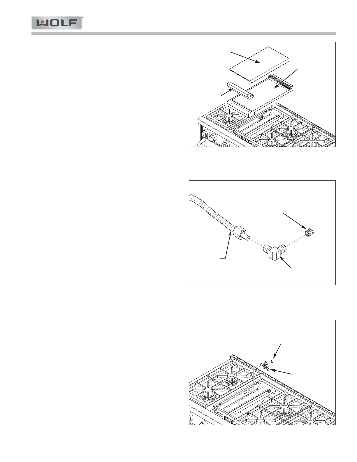
Trim Moldings and Burner Pan
There is trim moldings (L-shaped and/or T-shaped) for
each burner pan that run from front to back of the unit.
One moldings fits between the outer side assembly and
the burner pan, the other molding fits between burner
pans and grill grate or french cook top assembly,
depending on the model.
To remove the burner pan (See Figure 4-2):
1. Remove front and rear burner assemblies.
2. Lift trim moldings from each side of burner pan.
3. Lift burner pan off of unit.
Figure 4-1. Burner Assembly Removal
Figure 4-2. Trim Moldings
Burner Grate
Burner Cap
Screw
Screws
Burner
Assembly
Ignitor
Wire Lead
Burner Pan
Trim Moldings
Gas Range (GR) Series
Gas Range (GR) Series
Component Access & Removal
4-4
#822634 - Revision A - January, 2013
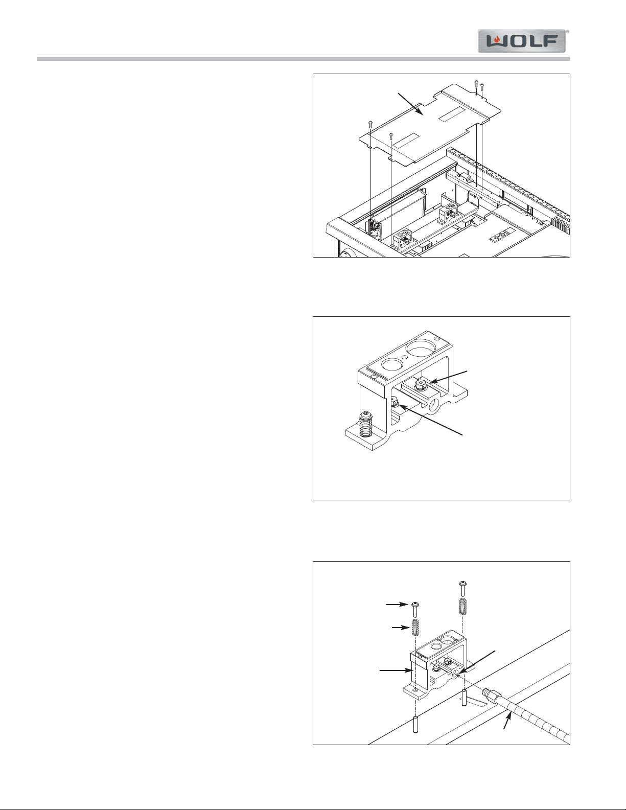
Burner Under Pan
The burner underpan is attached to the front and back
rail with screws.
To remove the burner under pan, first remove the grate,
burner assembly, trim molding and burner pan, then
(See Figure 4-3):
1. Extract the front and back mounting screws.
2. Lift the pan up.
Orifice Removal
The main and simmer orifice are threaded down into
the orifice holder and may be extracted without remov-
ing the orifice holder from its installation position.
To remove an orifice, first remove the grate, burner
assembly, trim molding, burner pan and under pan, then
use a 9/32” wrench to extract orifice from orifice holder.
(See Figure 4-4)
Orifice Holder
The orifice holder assembly is secured with screws to
the burner support panel. Each orifice holder assembly
consists of an orifice holder, the main and simmer ori-
fice and the mounting hardware. The orifice holder is
mounted with a stand-off and spring assembly which
allows the orifice holder to flex when the burner assem-
bly is installed.
To remove the orifice holder, first remove the grate,
burner assembly, trim molding, burner pan and under
pan, then (See Figure 4-5):
1. With a 3/8” and a 7/16” open end wrenches,
remove the gas supply lines from orifice holder.
2. Extract the screws securing the orifice holder.
3. Remove springs from standoffs, then lift orifice
holder up off of unit.
Figure 4-5 Orifice Holder Removal.
Screw
Spring
Orifice Holder
Main Gas
Supply Port
Main Orifice
Simmer Orifice
Gas Line
Figure 4-3. Burner Under Pan Removal.
Figure 4-4. Orifice Removal.
Burner Under Pan
Component Access & Removal
Gas Range (GR) Series
Gas Range (GR) Series
4-5
#822634 - Revision A - January, 2013
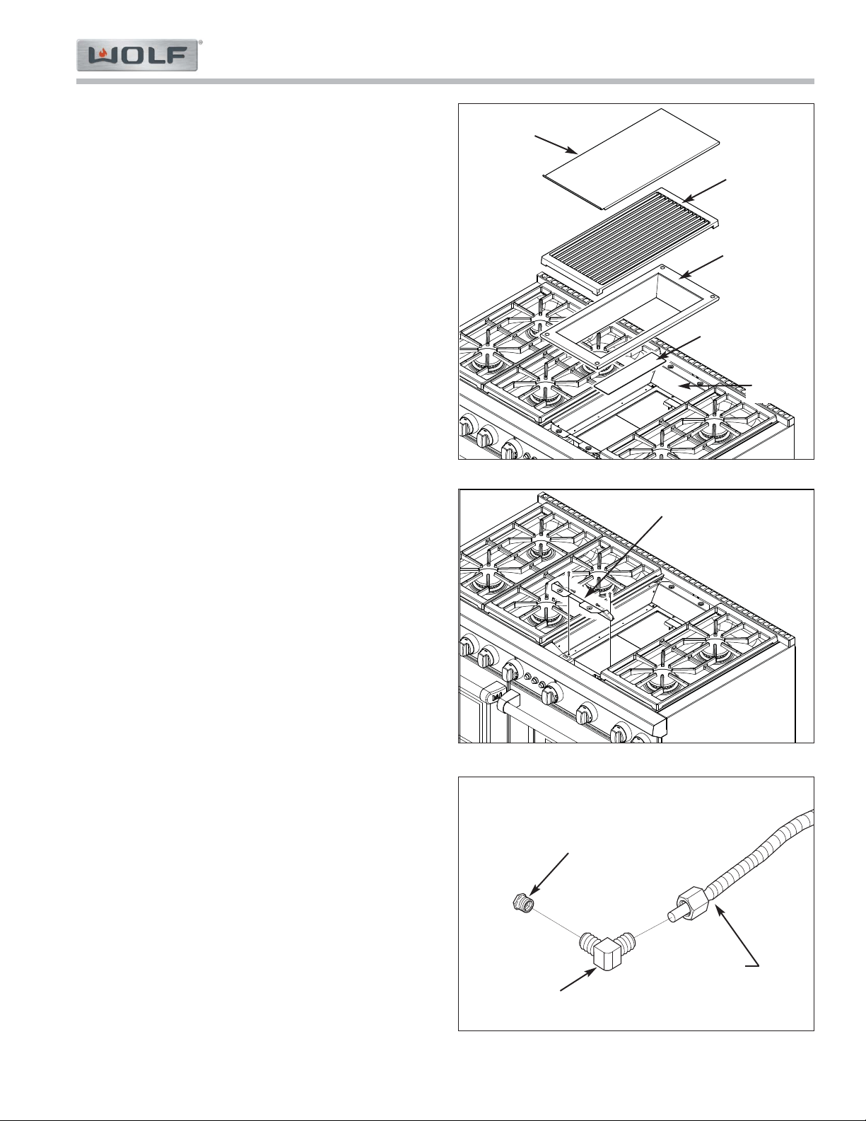
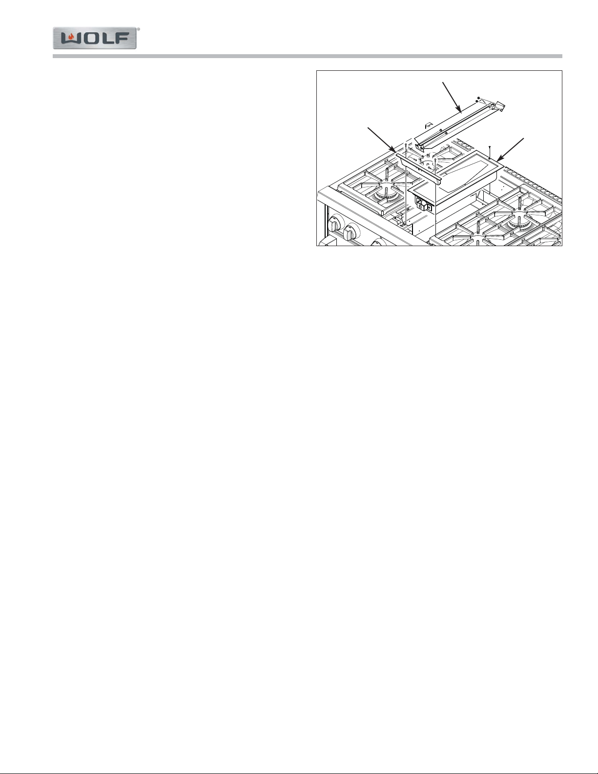
Figure 4-6. Charbroiler Top Components
Infrared Charbroiler Components:
Infrared Charbroiler Cover, Grate, Frame and Blank-
Off Plate (See Figure 4-6):
1. Lift charbroiler cover from top of grate.
2. Lift charbroiler grate from Frame.
3. Lift blank-off plate from top of charbroiler.
4. Lift charbroiler frame from top of support frame.
Infrared Charbroiler Orifice Removal
The orifice is located in the brass orifice elbow, which is
threaded into the orifice holder at front of burner box.
To remove the orifice, first remove the charbroiler cover,
grate, and frame, then (See Figures 4-7 and 4-8):
1. Extract front charbroiler support mounting screws,
then lift the support off of unit and set aside.
2. Using a wrench, disconnect gas line from brass ori-
fice elbow.
3. Unscrew orifice elbow from the orifice holder, and
extract the orifice from the elbow with wrenches.
Blank-off Plate
Frame
Grate
Cover
Support
Frame
Figure 4-7. Front Charbroiler Support Removal.
Figure 4-8. Charbroiler Orifice Removal.
Front Char Support
Orifice
Orifice Elbow
Gas Line
Gas Range (GR) Series
Gas Range (GR) Series
Component Access & Removal
4-6
#822634 - Revision A - January, 2013
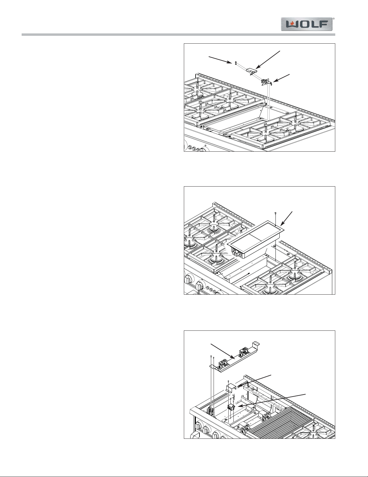
Infrared Charbroiler Electrode (Sparker)
The infrared charbroiler electrode assembly is attached
to the right side charbroiler support with screws. The
body of the electrode protrudes through a hole in the
support where the sparker wire is then attached to it.
The sparker wire then is routed to the spark module.
To remove the electrode assembly first remove char-
broiler cover, grate, and frame, then (See Figure 4-9):
1. Extract the assembly mounting screws from right
side charbroiler support.
2. Set the electrode shield off to the side.
3. Pull electrode out of the hole and up to expose the
sparker wire.
4. Disconnect sparker wire from electrode.
Infrared Charbroiler Burner Box
The side flanges of the charbroiler burner box sit on the
bottom flanges of the left, right and rear charbroiler sup-
ports. The supports are attached to support rails run-
ning from front to rear of the unit. A screw passes
through a notch at the rear of the burner box into the
rear charbroiler support. The front broiler support holds
the front of the burner box in place.
To remove the burner box, first remove the charbroiler
cover, grate, frame, blank-off plate and electrode.
Then, remove the front charbroiler support and discon-
nect the gas line from the orifice elbow. Now, (See
Figure 4-10):
1. Loosen the screw at the rear of the burner box.
2. Slide the burner box forward and lift it off of the side
charbroiler supports.
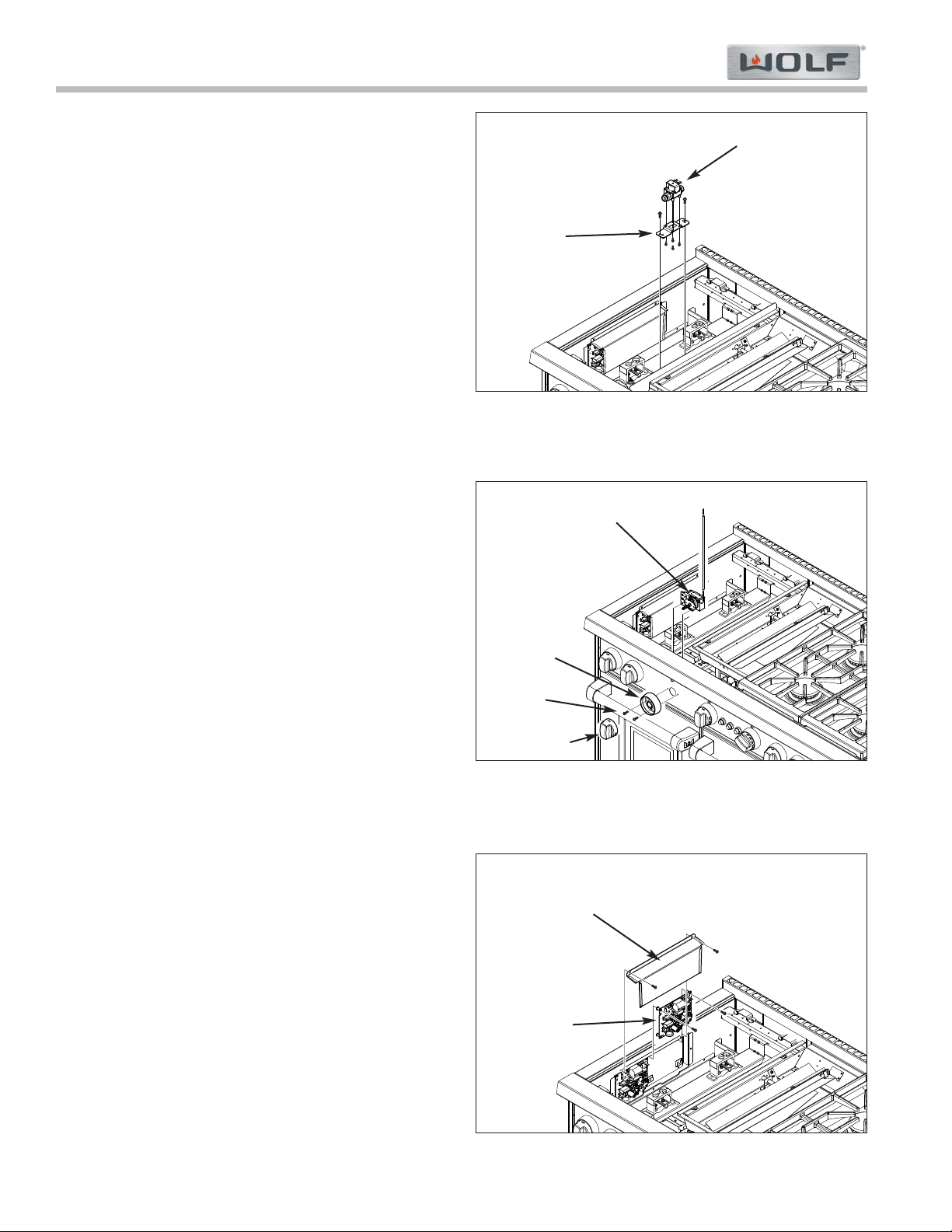
Spark Module
Most spark modules are situated under the burner sup-
port panels and covered by sparker shields.
To remove a spark module, first remove the grate, burn-
er assembly, trim molding, burner pan and under pan,
then, (See Figure 4-11):
1. Extract screws at front of burner support.
2. Lift front of burner support panel up and disengage
support panel’s rear flange from slot in back rail,
then move support panel off to the side.
NOTE: No need to remove parts from support
panel for this procedure.
3 Extract sparker shield’s mounting screw and lift
shield out of the way.
4. Disconnect wires from spark module.
5. Extract module’s mounting screws and lift module
up and off of mounting plate.
Figure 4-9. Charbroiler Electrode Removal.
Figure 4-10. Charbroiler Burner Box Removal.
Figure 4-11. Spark Module Removal.
Burner Box
Spark
Module
Sparker Shield
Burner Support
Panel
Screws
Electrode Shield
Electrode
Component Access & Removal
Gas Range (GR) Series
Gas Range (GR) Series
4-7
#822634 - Revision A - January, 2013
Infrared Griddle Components:
Griddle Cover, Grease Cup and Griddle Plate (See
Figure 4-12):
1. Lift griddle cover from top of griddle plate.
2. Lift grease cup out of griddle plate sump at front of
griddle plate.
3. Lift griddle plate from top of griddle assembly.
NOTE: Griddle plate is heavy.
Griddle Orifice
The orifice is located in the brass orifice elbow, which is
threaded into the orifice holder at front of griddle burner
box.
To remove the orifice, first remove the griddle cover,
grease cup and griddle plate, then (See Figures 4-13):
1. Using a wrench, disconnect gas line from brass ori-
fice elbow.
2. Unscrew orifice elbow from the orifice holder, and
extract the orifice from the elbow with wrenches.
Griddle Electrode (Sparker)
The griddle electrode assembly is attached to the side
griddle support with screws (Electrode is on left hand
side on a single griddle. On dual griddles, left hand
burner’s electrode is on the left side, and on the right
side of the right hand burner). The body of the elec-
trode protrudes through a hole in the support where the
sparker wire is then attached to it. The sparker wire
then is routed to the DSI board.
To remove the electrode assembly first remove the grid-
dle cover, grease cup and griddle plate, then (See
Figure 4-14):
NOTE: It should not be necessary to remove the ther-
mostat support assembly to remove the electrode.
1. Extract the assembly mounting screws from side
griddle support.
2. Pull electrode out of the hole and up to expose the
sparker wire.
3. Disconnect sparker wire from electrode.
Figure 4-12. Griddle Plate Removal.
Griddle Cover
Griddle Plate
Grease Cup
Figure 4-13. Griddle Orifice Removal.
Orifice
Orifice Elbow
Gas Line
Figure 4-14. Griddle Electrode Removal.
Electrode
Screws
Gas Range (GR) Series
Gas Range (GR) Series
Component Access & Removal
4-8
#822634 - Revision A - January, 2013
Griddle Solenoid
The solenoid is attached to a solenoid mount plate with
screws on the bottom side. The mounting plate is then
attached to a bracket on the electrode side of the burn-
er box enclosure.
To remove the solenoid, first remove the grate, burner
assembly, trim molding, burner pan and under pan on
the spark electrode side of the griddle, then (See Figure
4-15):
1. Disconnect electrical leads from solenoid.
2 Using a wrench, disconnect inlet and outlet gas
lines from solenoid.
3. Extract solenoid mounting plate screws, then
extract the screws at the bottom of the plate and lift
solenoid off of the mounting plate.
Griddle Thermostat
Screws under the thermostat knob pass through the
thermostat bezel and bullnose face, then thread into the
thermostat bracket, holding the thermostat to the back-
side of the bullnose face. The thermostat bulb is laid in
the cradle of the thermostat support assembly on a bed
of insulation, with the tip captivated by a tab formed at
the rear of the cradle and wire is wrapped around the
bulb at the front of the cradle.
To remove the thermostat, first remove the grate, burner
assembly, burner pan and under pan on the electrode
side of the griddle, then (See Figure 4-16):
1. Disconnect electrical leads from thermostat.
2. Remove thermostat knob and extract bezel/thermo-
stat mounting screws.
3. Unwrap wire from bulb at front of cradle.
4. Pull tip of bulb from under tab in thermostat support
assembly cradle, then remove the bulb from the
cradle and lift thermostat from the appliance.
DSI (Direct Spark Ignition) Board
The DSI board is attached to the side wall under the
burner pan on the same side as the appropriate griddle
electrode and an electronic cover is attached over it.
To remove a DSI board, first remove the grate, burner
assembly, trim molding, burner pan and under pan on
the spark electrode side of the griddle, then (See Figure
4-17):
1. Extract DSI board cover mounting screws and set
the cover off to the side.
2. Disconnect all electrical leads from DSI board.
3. Extract DSI board mounting screws, lift board slight-
ly and pull the board from the unit.
Figure 4-15. Griddle Solenoid Removal.
Figure 4-16. Griddle Thermostat Removal.
Figure 4-17. DSI Board Removal.
Solenoid
Solenoid
Mount
Plate
Thermostat
Bezel
Control Knob
Screws
DSI Board
DSI Board
Cover
Component Access & Removal
Gas Range (GR) Series
Gas Range (GR) Series
4-9
#822634 - Revision A - January, 2013
Griddle Burner Box
The side flanges of the griddle burner box sit on the
bottom flanges of the left, right and rear griddle sup-
ports. The supports are attached to support rails run-
ning from front to rear of the unit. A screw passes
through a notch at the rear of the burner box into the
rear griddle support. The front griddle support holds the
front of the burner box in place.
To remove the burner box, first remove the griddle
cover, grease cup and griddle plate, then disconnect
the gas supply line at the front. Now, (See Figures 4-
18):
1. Extract the thermostat support assembly mounting
screws from the front and back griddle supports
and move the assembly to the side.
2. Extract the front griddle support mounting screws
and remove the support to the side.
3. Loosen the screw at the rear of the burner box.
4. Slide the burner box forward and lift it off of the side
griddle supports.
Figure 4-18. Griddle Burner Box Removal.
Thermostat support Assembly
Front Griddle
Support
Burner Box
Gas Range (GR) Series
Gas Range (GR) Series
Component Access & Removal
4-10
#822634 - Revision A - January, 2013
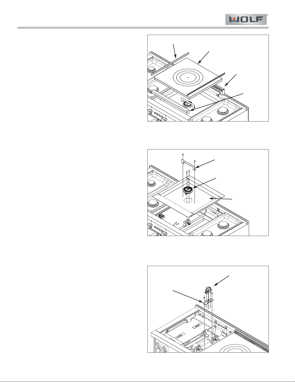
Figure 4-19. French Top Surface Removal
French Top Components:
French Top Surface Components
To remove components that make up the French Top
surface, the top cover must first be removed, then (See
Figure 4-19).
1. Lift trim molding from sides of french top.
2. Lift the center ring from the second ring, using the
French Top hook provided with the unit.
3. Lift the second ring from the third ring.
4. Lift the third ring from the top plate.
5. Lift the top plate from the unit.
6. Lift the front trim from the unit.
7. Lift the rear vent from the unit.
French Top Pan Weld Assembly and Burner Head
A burner head bracket is attached to the pan weld
assembly over the top of the burner body. Screws pass
through the burner body and then thread into the orifice
holder.
To remove the burner assembly, first remove the french
top surface components, then (See Figure 4-20):
1. Extract burner head bracket screws and remove
burner head bracket.
2. Extract screws securing burner head assembly to
orifice holder.
3 Lift burner head assembly off pan weld assembly
and disconnect wire lead from spark ignitor.
4. Lift the pan weld assembly up and off of the unit.
French Top Solenoid
The solenoid is attached to a solenoid mount plate with
screws on the bottom side. The mounting plate is then
attached to a bracket on the left side of the french top.
To remove the solenoid, first remove the grate, burner
assembly, trim molding, burner pan and under pan on
the left side of the french top, then (See Figure 4-21):
1. Disconnect electrical leads from solenoid.
2 Using a wrench, disconnect inlet and outlet gas
lines from solenoid.
3. Extract solenoid mounting plate screws, then
extract the screws at the bottom of the plate and lift
solenoid off of the mounting plate.
Figure 4-20. French Top Burner Head Removal
Figure 4-21. French Top Solenoid Removal
French Top Rings
and Top Plate
Rear Vent
Front Trim
Trim Molding
Burner Head Backet
Burner Head
Pan Weld Assy
Solenoid
Solenoid
Mount
Plate
Component Access & Removal
Gas Range (GR) Series
Gas Range (GR) Series
4-11
#822634 - Revision A - January, 2013
DSI (Direct Spark Ignition) Board
The DSI board is attached to the left side wall under the
burner pan and an electronic cover is attached over it.
To remove a DSI board, first remove the grate, burner
assembly, trim molding, burner pan and under pan on
the left side of the french top, then (See Figure 4-22):
1. Extract DSI board cover mounting screws and set
the cover off to the side.
2. Disconnect all electrical leads from DSI board.
3. Extract DSI board mounting screws, lift board slight-
ly and pull the board from the unit.
Figure 4-22. French Top DSI Removal
DSI Board
DSI Board
Cover
Gas Range (GR) Series
Gas Range (GR) Series
Component Access & Removal
4-12
#822634 - Revision A - January, 2013
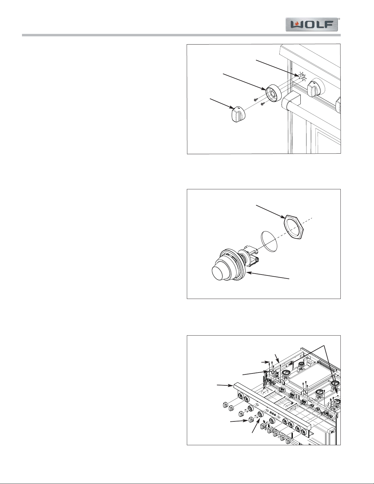
Bullnose Front / Control Panel and
Components Behind Bullnose:
Control Knob
Pull control knob off of valve or control shaft (See
Figure 4-23).
Control Knob Bezel
Screws pass through the bezel and are threaded into
the control panel, or they also pass through the control
panel and into a thermostat bracket, depending on the
appliance configuration.
To remove a bezel, the control knob must be removed
first, then extract the mounting screws and pull the
bezel from the appliance (See Figure 4-23):
Switch
A switch passes through the control panel and a nut is
threaded onto the back side to hold the switch in place.
To remove a switch, first remove the grate, burner
assembly, burner pan and under pan, then (See Figure
4-24):
1. Disconnect electrical leads from switch.
2. Unthread nut from back side of switch.
3. Pull switch from control panel.
Bullnose/Control Panel
To remove the bullnose/control panel, first remove the
grates, burner assemblies, burner pans and under
pans, then (See Figure 4-25):
1. Remove all control knobs.
2. Remove bezels from front of all thermostats
(oven(s), griddle(s))
3. Disconnect electrical leads from all switches.
4. Disconnect LED electrical leads.
5. Extract screws from hat brackets above bullnose
top flange mounting screws and remove hat brack-
ets.
6. Extract bullnose top flange mounting screws.
7. Extract Bottom flange screws.
8. Extract nut from manifold mounting stud.
NOTE: It may help to move the appropriate burner
support panel to the side for access to the nut.
Also, there are three nuts on 60” wide units.
9. Lift bullnose/control panel up to disengage from
locating screws at each end, then pull bullnose/con-
trol panel forward.
Figure 4-23. Control Knob and Bezel Removal
Shaft
Bezel
Knob
Figure 4-24. Switch Removal
Nut
Switch
Figure 4-25. Bullnose Removal
Manifold Mounting
Nuts
Bottom Flange
Mounting Screw
Top Flange Mounting Screw
Hat Bracket
Bullnose
Thermostat Bezel
Control Knob
Component Access & Removal
Gas Range (GR) Series
Gas Range (GR) Series
4-13
#822634 - Revision A - January, 2013
Gas Valve
The gas valve is mounted to the top of the manifold
with a bolt that passes through the bottom manifold wall
and threads up into the gas valve body. The gas valve
sits upon a rubber gasket, while the retaining bolt has
an O-ring to prevent gas leaks.
To remove the gas valve, the bullnose assembly must
be removed first, then, (See Figure 4-26):
1. Disconnect electrical leads from valve.
2. Disconnect gas lines from valve.
3. Extract bolt from underside of manifold tube.
4. Pull or twist the valve off of the top of manifold tube.
Gas Valve Orifice
Each gas valve has two bypass screw orifices installed
on the front side of the valve body.
To remove these orifices, the bullnose assembly must
be removed first, then use a small flat bladed screwdriv-
er and turn the bypass screw orifice counterclockwise to
remove, and pull the orifice out of the valve (See Figure
4-27).
Micro-Switch
Surface Burner Micro-Switch - The surface burner
microswitches are attached to the valve fronts with
screws.
To remove a surface burner micro-switch, the bullnose
assembly must be removed first, then (See Figure 4-
28):
1. Disconnect electrical leads from switch.
2. Extract mounting screws and pull switch from valve.
Charbroiler Micro-Switch - To remove a charbroiler
micro-switch, the bullnose assembly must be removed
first, then remove a micro-switch from a Charbroiler
burner valve by disconnecting the wire leads to the
switch. Then, pull the switch from the valve shaft (Not
Shown).
Figure 4-26. Gas Valve Removal
Gas Valve
Bolt
with O-ring
Rubber Gasket
Electrical Leads
Gas Lines
Figure 4-27. Gas Valve Orifice Removal
Gas Valve Orifice
Figure 4-28. Surface Burner Micro-Switch Removal
Gas Valve
Micro-Switch
Gas Range (GR) Series
Gas Range (GR) Series
Component Access & Removal
4-14
#822634 - Revision A - January, 2013
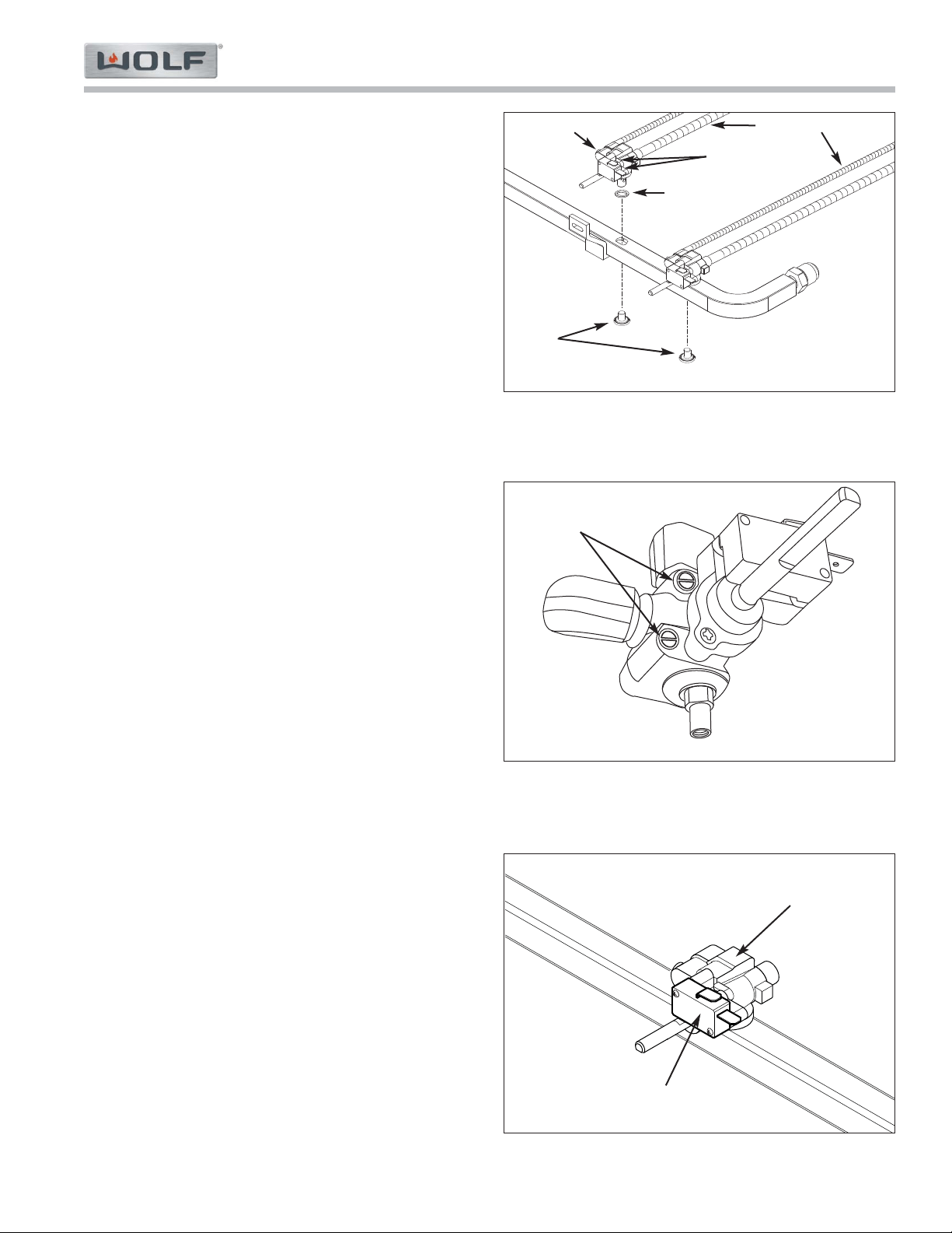
Manifold
The manifold is a formed aluminum tube that connects
to flex tubing leading from the gas regulator, and has
ports in which the gas valves are mounted
To remove the manifold first remove the bullnose, then
(See Figure 4-29):
1. Cut cable ties securing wiring harness to manifold.
2. Remove gas valves from manifold.
3. Using wrenches, unthread gas supply line from
manifold nipple.
4. Pull manifold forward.
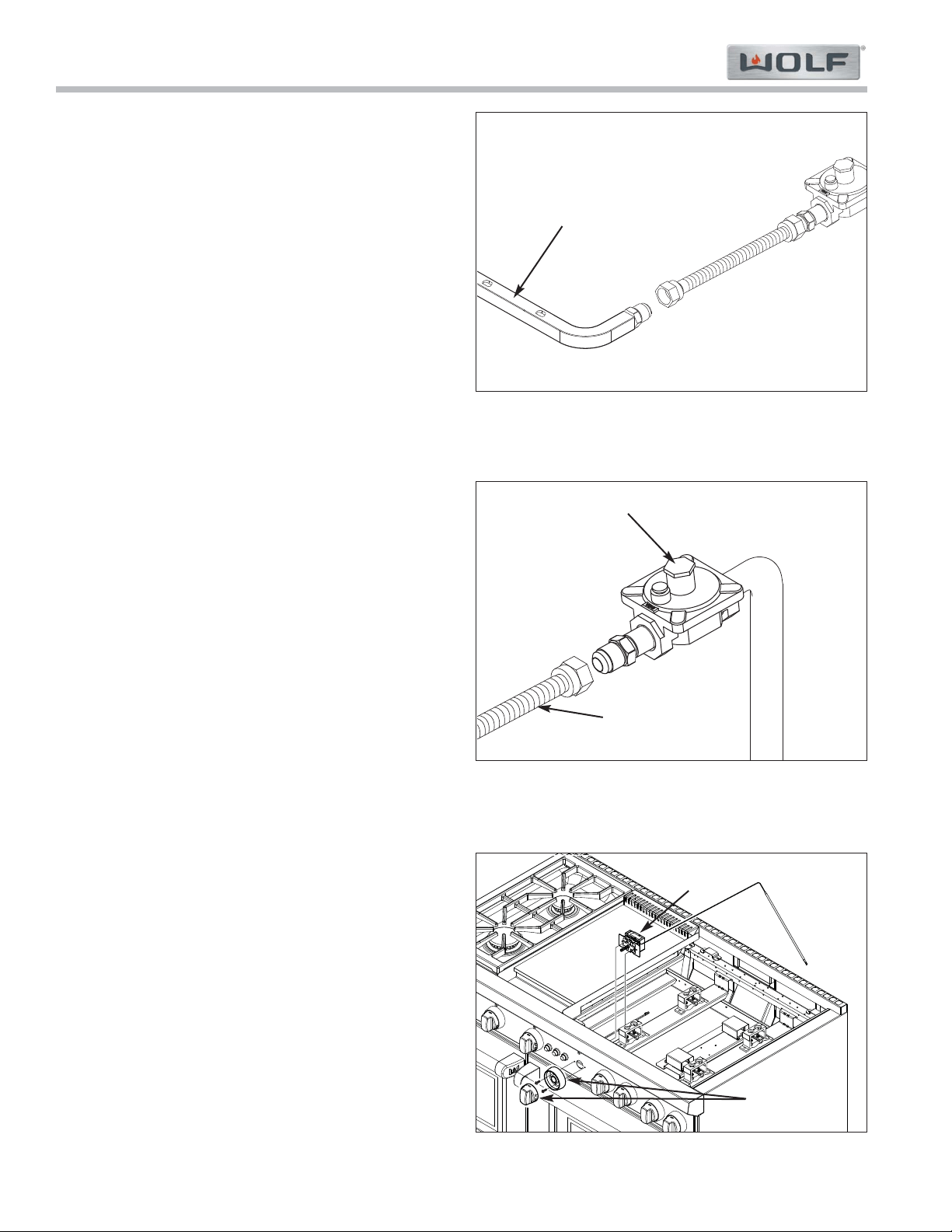
Gas Regulator
The gas regulator is located at the rear right corner
under the burner pan.
To remove the regulator, first remove the grate, burner
assembly, burner pan and under pan on the right side
of the unit, then (See Figure 4-30):
1. Using wrenches, unthread flexible gas line from
regulator nipple.
2. Using wrenches, unthread regulator from inlet gas
pipe.
Oven Thermostat
Screws under the thermostat knob pass through the
thermostat bezel and bullnose face, then thread into the
thermostat bracket, holding the thermostat to the back-
side of the bullnose face. The oven thermostat bulb is
routed to the back of the appliance where is passes
through a hole into the back of the oven and held in
place at the top rear of the oven in a thermostat brack-
et.
To remove the thermostat, first remove the grate, burner
assembly, burner pan and under pan above the thermo-
stat, then (See Figure 4-31):
1. Disconnect electrical leads from thermostat.
2. Remove thermostat knob and extract bezel/thermo-
stat mounting screws.
3. Inside the oven extract thermostat bulb bracket
mounting screws and slide bracket off of the bulb.
4. Push thermostat bulb back through the hole.
5. Once out of the hole, lift assembly off of appliance.
Figure 4-29. Manifold Removal
Manifold
Figure 4-30. Gas Regulator Removal
Inlet Gas Pipe
Regulator
Flexible gas line
Figure 4-31. Oven Thermostat Removal
Oven
Thermostat
Control Knob
& Bezel
Component Access & Removal
Gas Range (GR) Series
Gas Range (GR) Series
4-15
#822634 - Revision A - January, 2013
Lower Front Panel and Components
behind Lower Front Panel:
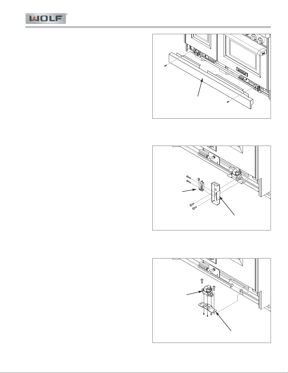
Lower Front Panel
The lower front panel has notches at the inner end
flanges that fit up under screw heads, then screws are
inserted through the top flanges at each end to hold the
panel in place.
To remove the lower front panel (See Figure 4-32):
1. With oven door(s) closed, extract screws from the
top flanges.
2. Let panel drop slightly while rotating top of panel
forward.
Door Switch
The door switch is attached to the switch bracket
assembly with screws.
To remove the door switch first remove the lower front
panel, then (See Figure 4-33):
1. With oven door(s) closed, extract back screws from
bracket assy.
2. Pull assembly forward and disconnect electrical
leads from switch.
3. Extract switch mounting screws and pull switch
from bracket assembly.
Oven Solenoid
The solenoid is attached to a solenoid mount plate with
screws on the bottom side. The mounting plate is then
attached to the lower front rail.
To remove the solenoid, first remove the lower front
panel, then (See Figure 4-34):
1. Disconnect electrical leads from solenoid.
2 Using a wrench, disconnect inlet and outlet gas
lines from solenoid.
3. Extract solenoid mounting plate screws, then
extract the screws at the bottom of the plate and lift
solenoid off of the mounting plate.
Figure 4-32. Lower Front Panel Removal
Lower Front Panel
Figure 4-33. Door Switch Removal
Door Switch
Bracket Assembly
Figure 4-34. Oven Solenoid Removal
Oven Solenoid
Bracket
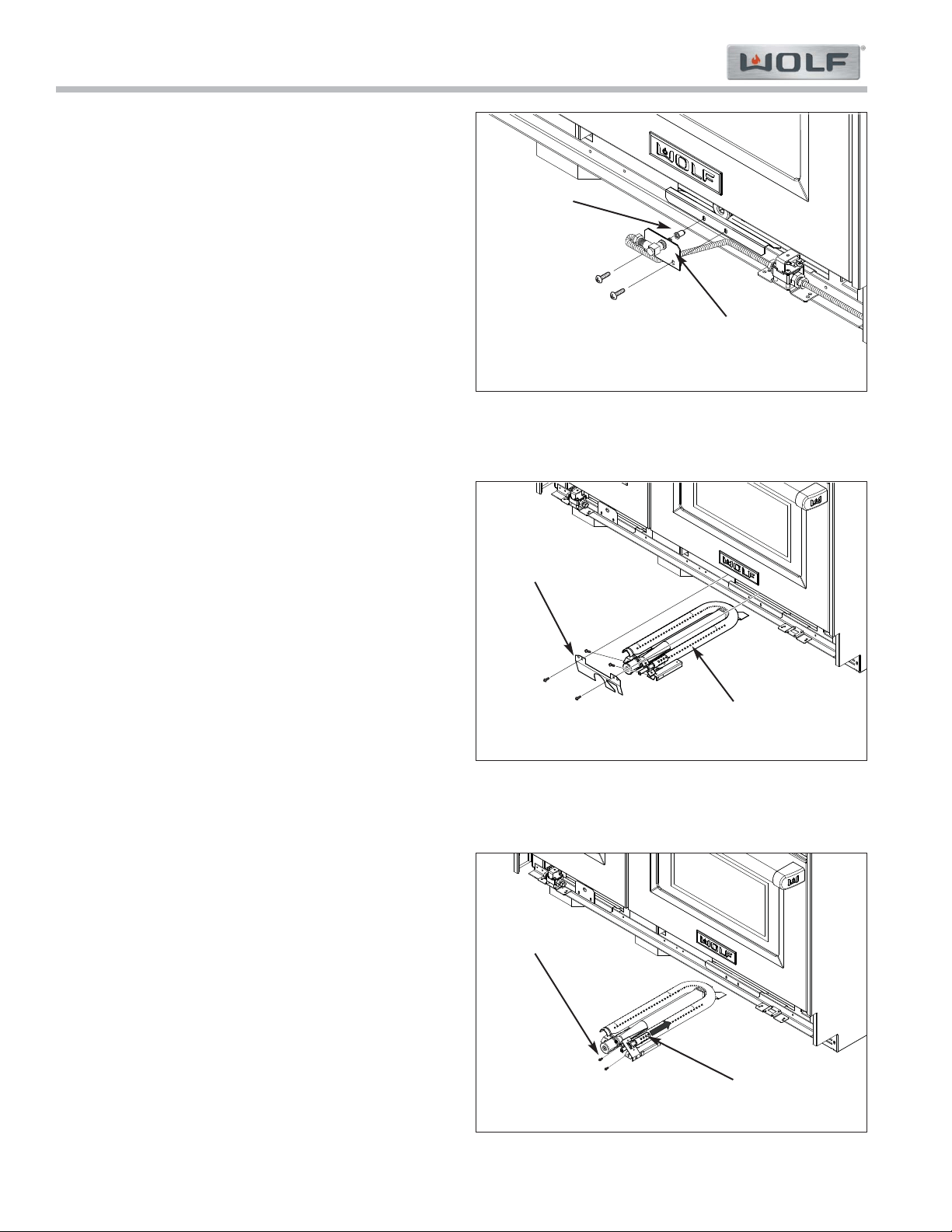
Gas Range (GR) Series
Gas Range (GR) Series
Component Access & Removal
4-16
#822634 - Revision A - January, 2013
Oven Bake Orifice
The oven bake orifice is attached to the end of the ori-
fice elbow and the orifice nose enters the oven burner.
The orifice elbow passes through the orifice bracket and
nuts on each side of the bracket hold it to the bracket.
The bracket is attached to the lower front rail with
screws that pass through it and the burner shield then
thread into the rail.
To remove the orifice, first remove the lower front panel,
then (See Figure 4-35):
1. Extract orifice bracket mounting screws and pull
assembly forward..
2 Using wrenches, remove orifice from end of elbow.
Oven Bake Burner Tube
The oven bake burner tube is attached to the burner
floor with screws at the front and a notch at the back of
the burner tube is captivated by a screw head. This all
sits behind the front baffle and under the bottom panel.
To remove the bake burner tube the lower front panel
and orifice bracket will need to be removed first, then
(See Figure 4-36):
1. Extract front baffle mounting screws and pull baffle
forward.
2. Unplug electrode wire from electrode.
3. Extract burner mounting screws and pull assembly
forward.
Oven Bake Electrode
The oven bake electrode is attached with screws to a
bracket that is attached to the bake burner tube.
To remove the oven electrode the lower front panel, ori-
fice bracket and bake burner tube will need to be
removed first, then (See Figure 4-37):
1. Extract electrode bracket mounting screws from
burner tube bracket.
2. Pull electrode bracket toward the rear of the burner
tube, lifting slightly to clear the top front edge of the
burner tube.
Figure 4-35. Oven Bake Orifice Removal
Orifice
Orifice Bracket
Figure 4-36. Oven Burner Tube Removal
Front Baffle
Burner Tube
Figure 4-37. Oven Bake Electrode Removal
Mounting Screws
Electrode
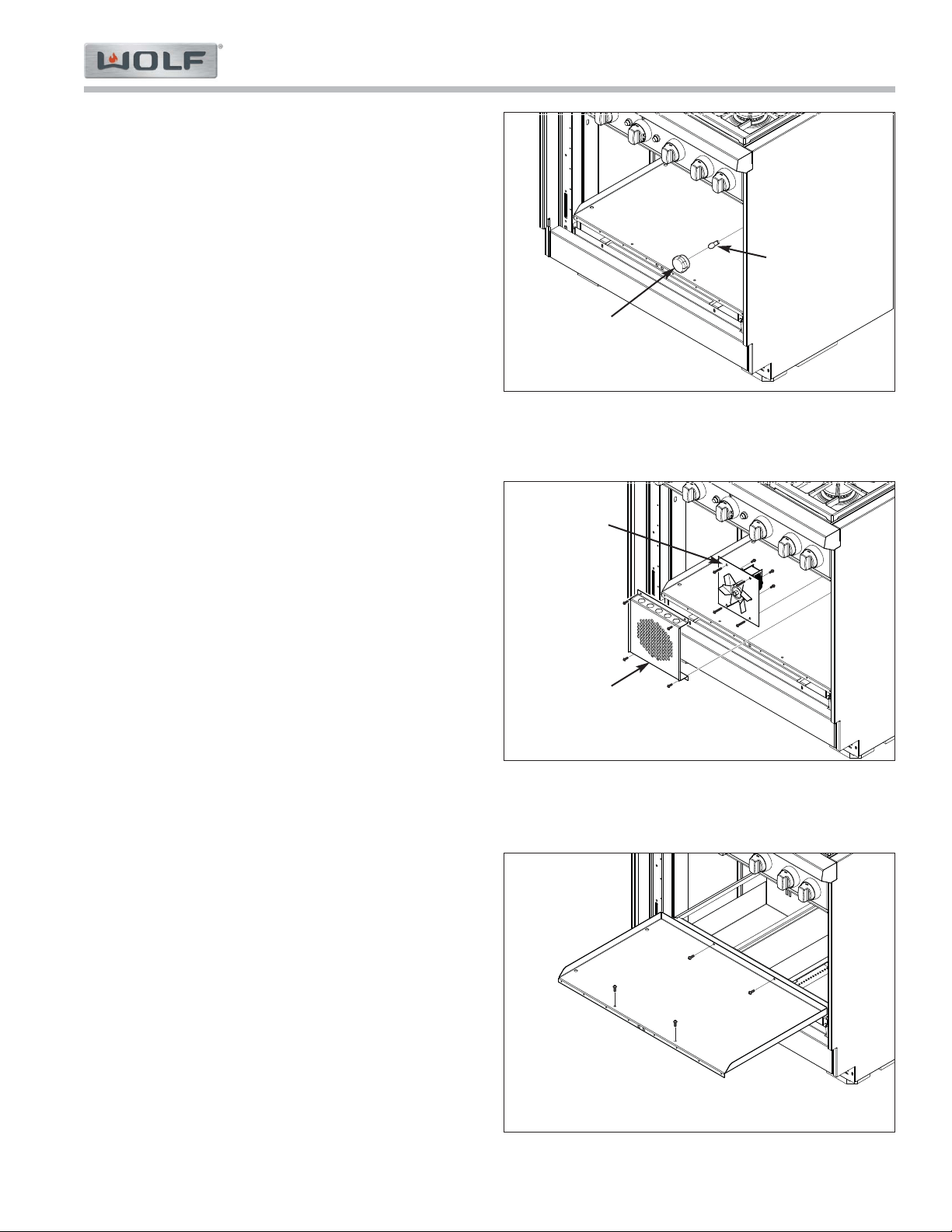
Component Access & Removal
Gas Range (GR) Series
Gas Range (GR) Series
4-17
#822634 - Revision A - January, 2013
Oven Compartment Components:
Oven Rack Guide
The tops of the oven rack guides are hooked up into
holes in the side walls. The bottom of the rack guides
are lowered down into holes in the bottom oven panel.
To remove an oven rack guide, first remove all oven
racks, then (no diagram):
1. Lift rack guide straight up and pivot the bottom
towards center of oven.
2. Pull rack guide down out of holes in side wall and
out of oven compartment.
Oven Light
To access and remove the oven light begin by unscrew-
ing the light lens. The Halogen light bulb can now be
removed by pulling it from the light socket (See Figure
4-38).
Convection Fan
The convection fan assembly is held to the back wall
with screws. The oven blower cover is positioned in
front of the fan assembly and also held to the back wall
with screws.
To remove the fan assembly (See Figure 4-39):
1. Extract blower cover mounting screws and pull
cover from the oven.
2. Extract fan assembly mounting screws and pull fan
assembly forward slightly, then disconnect fan’s
electrical leads and pull assembly from oven.
3. Remove blade from shaft of fan motor by spinning
nut “clockwise” (reverse thread).
4. Remove E-ring from fan shaft.
5. Extract fan motor mounting screws from rear of
plate and pull fan from plate.
Oven Bottom Panel
To remove the bottom oven panel, extract the screws at
the front and back, pull the door gasket from the front
flange, then lift the panel up and out of the oven (See
Figure 4-40).
Figure 4-39. Convection Fan Removal
Convection
Fan Assembly
Blower Cover
Figure 4-38. Oven Light Removal
Halogen Bulb
Light Lens
Figure 4-40. Oven Bottom Panel Removal
Bottom Panel
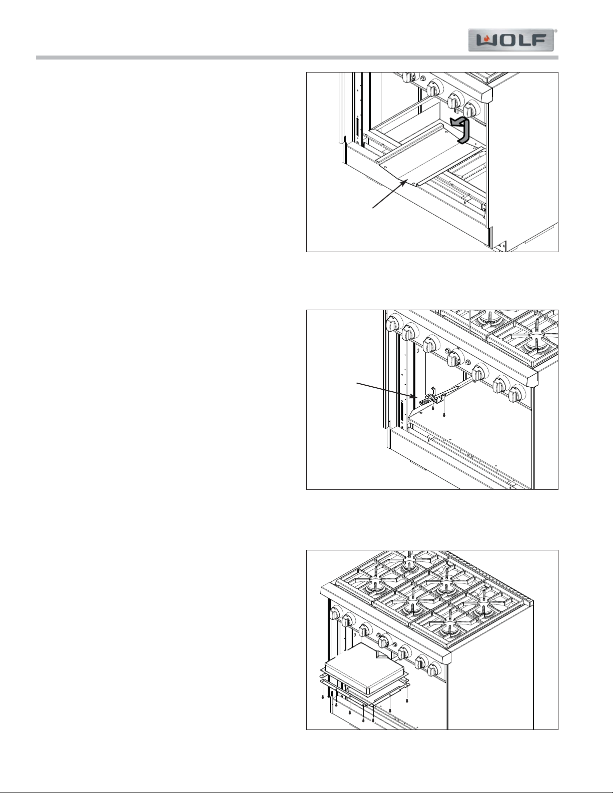
Gas Range (GR) Series
Gas Range (GR) Series
Component Access & Removal
4-18
#822634 - Revision A - January, 2013
Oven Flame Deflector
The oven flame deflector sits on top of two deflector
rests, one at the front and one at the back of the oven
compartment.
Removing the flame deflector requires the racks, rack
guides and the bottom oven panel to be removed first.
Then, lift the rear of the deflector up, then the front and
pull backward to clear the front mounting screws, now
pull the deflector from the compartment. (See Figure 4-
41).
Broil Electrode Assembly
The bracket of the broil electrode assembly is attached
to the ceiling of the cavity just behind the broiler with
screws. Its wire then leads up the back of the appli-
ance and under the burner pan to the DSI board
To remove the broil electrode assembly (See Figure 4-
42):
1. Extract the broil electrode assembly mounting
screws.
2. Pull the assembly forward so that the wires are in
the compartment, then disconnect the wire from the
electrode and pull the assembly from the compart-
ment.
Infrared Broiler Burner
The broiler burner box sits in a pocket in the top of the
oven compartment. The broiler burner box is held in
place in the ceiling by four brackets placed over the
edges of the burner box. The brackets are then
secured to the top of the oven with screws. The burner
mixing tube runs from the burner box to the rear of the
appliance.
In order th remove the broiler burner, the unit must be
pulled from its installation and the back panel and flue
removed, then (See Figure 4-43):
1. At back of unit disconnect gas line from orifice
elbow.
2. Inside the oven, extract the broil electrode mounting
screws and let electrode dangle.
3. Inside the oven, extract burner bracket mounting
screws.
4. Lower the broiler burner box down at the front
slightly, then pull it forward, down and out of the
oven.
Figure 4-41. Flame Deflector Removal
Flame
Deflector
Figure 4-42. Burner Tube & Igniter Removal
Broil
Electrode
Assembly
Figure 4-43. Broiler Burner Removal
Burner Box
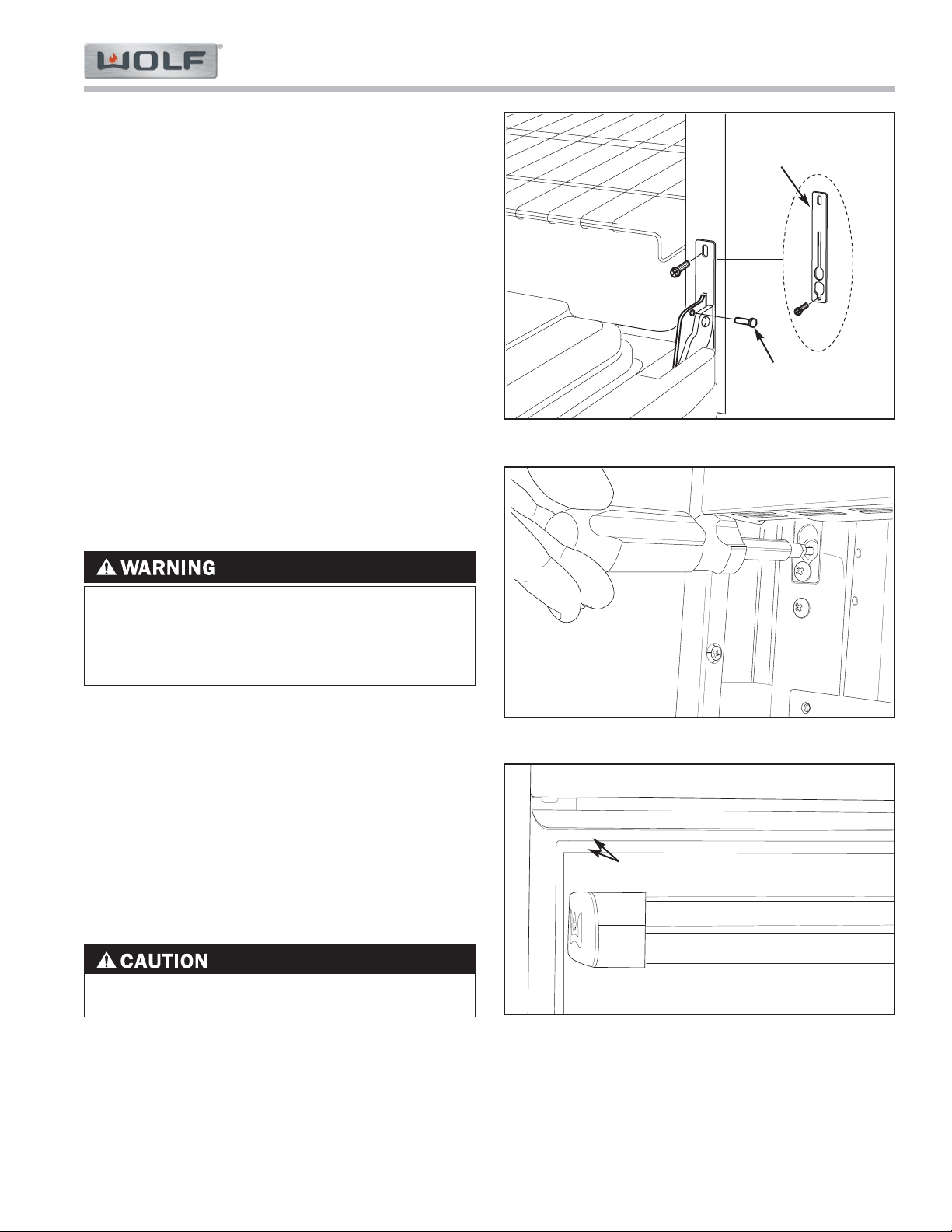
Component Access & Removal
Gas Range (GR) Series
Gas Range (GR) Series
4-19
#822634 - Revision A - January, 2013
Failure to screw in the bottom screw of hinge
retainer plate, will lead to future failure.
Oven Door:
Oven Door
oven doors use a spring and damper system. One
hinge arm is spring loaded, which requires the use of
the hinge pin for removal.
NOTE: For 30” and 36” units, the spring loaded hinge
arm is located on the right side of door, as you face it.
For 48'' and 60'' units, the hinge is on the right side of
the right door and on the left side of the left door.
To remove an oven door the lower front panel must be
removed first, then (See Figure 4-44):
1. Remove bottom screws securing retainer plates to
unit.
2. open door to full open position.
3. Insert hinge pin through hole in spring loaded hinge
arm (see NOTE above).
4. Close door until pin stops travel.
5. Lift up on the door while continuing to pull door
away from unit.
- FAILURE TO INSERT SUPPLIED PIN IN APPRO-
PRIATE HINGE ARM WILL CAUSE DAMAGE TO
UNIT, AND INJURIES MAY OCCUR.
- DO NOT LIFT OR CARRY OVEN DOOR BY DOOR
HANDLES.
Figure 4-44. Hinge pin and retainer plate
Figure 3-45. Door adjustment
Figure 3-46. Door adjustment
Adjust Gap
Door Adjustments
To adjust doors for height, use a 5/32” allen wrench to turn allen screw for the hinge pocket. This will raise or lower
the oven door to the desired height allowing for proper alignment. (See Figures 4-45 & 4-46).
Hinge
Retainer Plate
Hinge Pin
NOTE: Door(s) Reinstallation
To reinstall door assembly, fully extend hinge claw of
hydraulic damper hinge. Hold oven door on opposite
sides, lift door until hinges are aligned with hinge open-
ings in the oven frame. Now, insert hinge claw of
hydraulic damper hinge into hinge pocket before insert-
ing the spring side hinge. Then, position door in hinge
openings at a 30° angle from vertical. Insert spring side
hinge into hinge pocket. Lower door to fully opened
position and remove hinge pin. Reinstall plate and
screw over hinge opening. Then, open and close door
to insure proper installation.
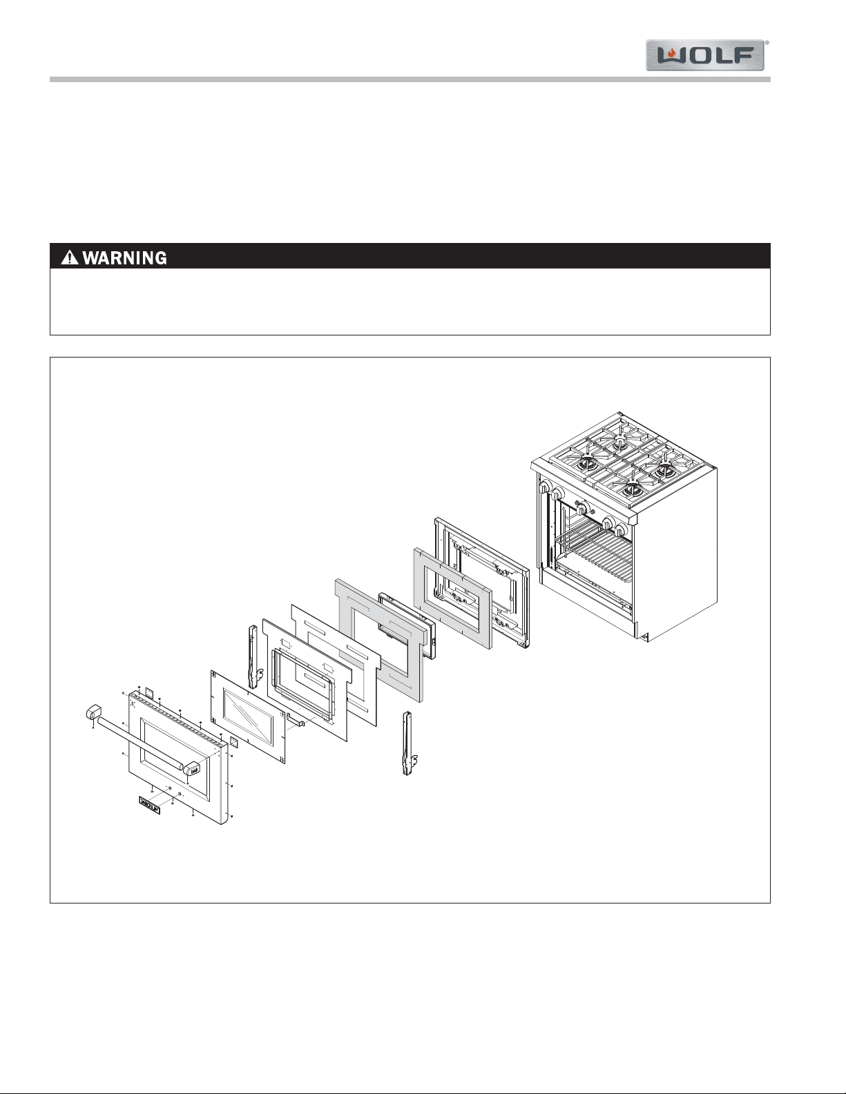
Gas Range (GR) Series
Gas Range (GR) Series
Component Access & Removal
4-20
#822634 - Revision A - January, 2013
Figure 4-47. Disassembling Oven Door
Oven Door Components:
Disassembling Oven Door
If it is necessary to access or remove any of the components that make up the door assembly, extract all of the
screws around the edge of the door and pull the door skin from the liner. This will allow the removal of all of the
door assembly components (See Figure 4-47).
NOTE: The hinge pocket is not replaceable.
DO NOT LIFT OR CARRY OVEN BY DOOR HANDLE. DO NOT LIFT OR CARRY INDIVIDUAL DOOR BY DOOR
HANDLE. FAILURE TO ADHERE TO THESE WARNINGS WILL RESULT IN DAMAGE TO UNIT AND/OR COM-
PONENTS OF UNIT, AND POSSIBLE INJURIES MAY OCCUR.
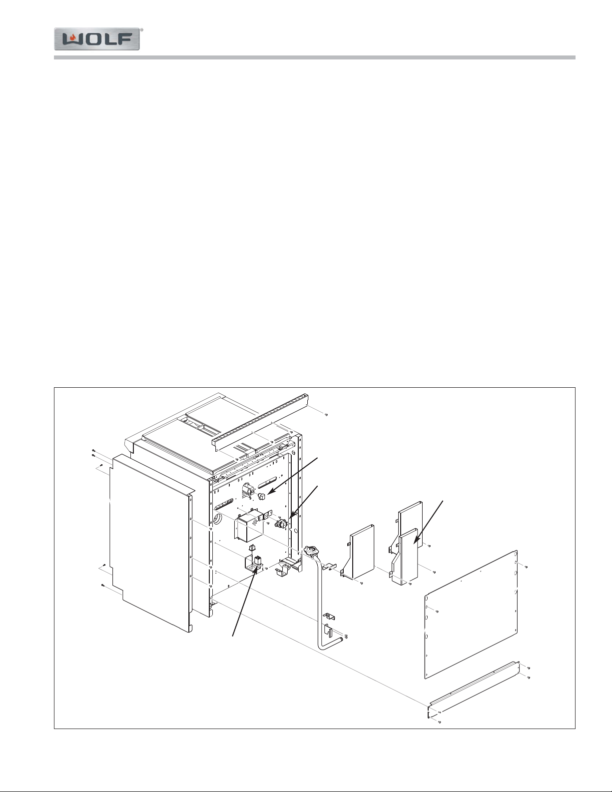
Component Access & Removal
Gas Range (GR) Series
Gas Range (GR) Series
4-21
#822634 - Revision A - January, 2013
Side Panels & Components on Rear of Unit (Refer to Figure 4-48):
NOTE: To remove the side panels and the components on the rear of the unit, the appliance must be s pulled from
its installation and the back panel removed.
Side Panel
To remove a side panel, first remove the bullnose and riser. Extract the screws from the panel’s back, front-bottom
and front-top flanges. Now, lift the side panel slightly, pivot it toward the front and while pulling the top away from
the appliance then the bottom.
Oven Broiler Solenoid
To remove the oven broiler solenoid, first disconnect electrical leads and gas lines. Then, extract bracket mounting
screws, now extract solenoid mounting screws from bracket.
Oven Broiler Orifice Elbow
The broiler orifice elbow is threaded into the broiler orifice holder on the back end of the broiler mixing tube. To
remove the orifice, first remove the flue which covers the orifice holder. Disconnect the gas line from the brass
elbow and unscrew the elbow from the orifice holder.
Fan Relay
To remove a fan relay, first disconnect all the wire leads at the relay. Then, extract the relay mounting screws and
lift the relay from the bracket.
Figure 4-48. Side Panel and Components on Rear of Unit
Side Panel
Fan Relay
Broiler Orifice Elbow
Flue
Broiler Solenoid
NOTE: Bullnose must
be removed for side
panel removal.
Gas Range (GR) Series
Gas Range (GR) Series
Troubleshooting Guide
5-2
#822634 - Revision A - January, 2013
TROUBLESHOOTING GUIDE
This section of the manual contains the General Troubleshooting Guide which will help the Service Technician trou-
bleshoot a Wolf Dual Fuel Range.
How to Use the Troubleshooting Guide
The troubleshooting guide table of contents shows how the troubleshooting guide is laid out. The troubleshooting-
guide is organized into component areas with the most common problems listed first.
On the table of contents identify the description of the problem that the unit is experiencing. To the left of the prob-
lem description is a letter. Locate that letter in the left column of the Troubleshooting Guide. The center column of
the troubleshooting guide will identify the possible causes for the problem. The information to the right of the possi-
ble causes will explain what tests to perform in order to determine if what you are checking is the cause, and/or what
action to take to correct the problem.
page #
Problems Associated with the Surface Burners
A. Constant Sparking ...................................................... 5-3
B. Intermittent Spark ...................................................... 5-3
C. Poor Ignition .............................................................. 5-3
D. No Ignition .................................................................. 5-3
E. Flame Appearance .................................................... 5-3
1. Tall Flame
2. Yellow Flame
3. Pulsing Flame
4. Small Flame
Problems Associated with the Charbroiler
F. Constant Sparking ...................................................... 5-4
G. Intermittent Spark ...................................................... 5-4
H. Poor Ignition .............................................................. 5-4
I. No Ignition . ................................................................ 5-4
J. Uneven Heat .............................................................. 5-4
K. Too Hot ...................................................................... 5-4
Problems Associated with the Griddle
L. Constant Sparking ...................................................... 5-5
M. Intermittent Spark ...................................................... 5-5
N. Poor Ignition .............................................................. 5-5
O. No Ignition .................................................................. 5-5
P. Cannot Regulate Temperatures ................................ 5-5
Q. “CFH” Indicator Lght Flashing at a Rate of 1 Flash per
Second and NO Heat on Griddle Surface .................. 5-6
R. “CFH” Indicator Lght Flashing at a Rate of 5 Flashes per
Second and NO Heat on Griddle Surface .................. 5-6
S. “CFH” Indicator Lght OFF and NO Heat on Griddle
Surface ...................................................................... 5-6
Troubleshooting Guide Table of Contents
page #
Problems Associated with the French Top
T. Constant Sparking ...................................................... 5-7
U. Intermittent Spark ...................................................... 5-7
V. Poor Ignition .............................................................. 5-7
W. No Ignition .................................................................. 5-7
X. Uneven Heat ................................................................5-8
Y. Not Enough Heat at Center ..........................................5-8
Z. Flame keeps going out ................................................5-8
Problems Associated with the Oven
AA. Oven Burner Does Not Light ........................................5-9
BB. Oven Burner too hot or cold for setting ........................5-9
CC. Oven Burner Delayed Ignition ......................................5-9
DD. Oven Burner Rushing Noise ......................................5-10
EE. Oven Burner Yellow Flame ........................................5-10
FF. Oven Broiler Does Not Light ......................................5-10
GG. Oven Broiler Delayed Ignition ....................................5-10
HH. Oven Broiler Rushing Noise ......................................5-10
II. Convection Fan does not Switch ON ........................5-11
JJ. Convect Fan does not Switch OFF with Door Open ..5-11
KK. Problems Associated with the Lights ..........................5-11
DSI Troubleshooting Flowchart (0, 1)
.......................... 5-12
DSI Troubleshooting Flowchart (0, 2) .......................... 5-13
Troubleshooting Guide
Gas Range (GR) Series
Gas Range (GR) Series
5-3
#822634 - Revision A - January, 2013
PROBLEM POSSIBLE CAUSE TEST / ACTION
A. CONSTANT SPARKING AT
SURFACE BURNER
B. INTERMITTENT SPARKING
AT SURFACE BURNER
C. POOR IGNITION AT SUR-
FACE BURNER
D. NO IGNITION AT SURFACE
BURNER
E. FLAME APPEARANCE ON
SURFACE BURNER(S)
1. Tall Flame
2. Yellow Flame
3. Pulsing Flames
4. Small Flame
Ground wire disconnected at outlet or
inside unit
Spark module wired incorrectly or
defective
Electrode dirty or defecvtive
Burner head not properly positioned on
inner distribution ring
Defective micro switch at burner valve
Cut or splice in electrode wire
Defective spark module
Dirty electrode
Dirty or Wet Burner ports
Cracked or damaged electrode
Cut or splice in electrode wire
Loose wire connection at spark module
Defective spark module
Burner head not properly seated on inner
distribution ring
Electrode spark wire disconnected
Partially plugged ports in burner head
Debris in burner ports
Improper Gas orifice
Gas pressure
Improper gas type
Regulator set for wrong gas
No Power
Defective micro-switch at burner valve
Defective/dirty electrode
Defective or loose wiring
Defective spark module
No gas to unit
Burner cap not positioned properly
Burners not getting enough primary or sec-
ondary air
Port holes in burner head not to specifica-
tion or damaged/dirty
Incorrect gas orifices
Gas pressure
Improper gas type
z
May have to call an electrician. Check internal
connections, may have to wire correctly
Rewire spark module(s) or replace
Clean or replace
Rotate to correct position and advise owner
Replace micro switch
Replace electrode wire
Replace spark module
Clean with wire brush
Clean or dry ports
Replace electrode/burner assembly
Replace electrode wire
Repair wire connection
Replace spark module
Rotate to correct position and advise owner
Reconnect wire
Clear/clean as necessary
Clean/remove debris
Check orifice stamp number
Check gas pressure with a manometer
Check for gas type and advise owner if improp-
er. May have to convert unit to LP/Natural gas
Reset regulator
Check outlet and circuit breaker
Replace micro switch
Replace/clean electrode/burner assy
Replace/repair wiring
Replace spark module(s)
Check gas pressure with a manometer
Make sure burner cap is seated in properly
Make sure air vents at front of burner box are
not blocked
Replace/clean burner head
Check stamp number on orifices
Check gas pressure using a manometer
Check for gas type and advise owner if improp-
er. May have to convert unit to LP/Natural gas
Problems Associated with the Surface Burners
Gas Range (GR) Series
Gas Range (GR) Series
Troubleshooting Guide
5-4
#822634 - Revision A - January, 2013
PROBLEM POSSIBLE CAUSE TEST / ACTION
F. CONSTANT SPARKING AT
CHARBROILER
G. INTERMITTENT SPARKING
AT CHARBROILER
H. POOR IGNITION AT
CHARBROILER
I. NO IGNITION AT
CHARBROILER
J. UNEVEN HEAT AT
CHARBROILER
K. CHARBROILER TOO HOT
Partially plugged holes in the burner tile
Electrode dirty or defecvtive
Defective micro switch at burner valve
Spark module wired incorrectly or
defective
Arcing at spark module to bracket or unit
chassis
Dirty electrode
Partially plugged holes in the burner tile
Blank-off plate in improper position
Cracked or damaged electrode
Defective micro switch at burner valve
Arc at cut or splice in electrode wire
Defective spark module
Blank-off plate in improper position
Electrode not positioned properly to
Infrared burner, not close enough to tile
surface
Cracked or damaged electrode
Partially plugged holes in the burner tile
Wrong orifice size
Blockages in mixing tube or orifice
Gas pressure
Bent orifice bracket holder
Improper gas type
Defective micro switch
Loose or bad wire connection
Defective sparker
Defective spark module
No power
No gas
Short to spark module bracket unit chassis
Blank-off plate not in correct position or
installed
May be normal
Blank-off plate not installed
Incorrect orifice
Clear as necessary with wire paper clip.
Replace burner if too many burner holes are
clogged.
Clean or replace
Replace micro switch
Rewire spark module(s) or replace
Check for break in insulation or missing
Clean debris from electrode
Clear as necessary with wire paper clip.
Replace burner if too many burner holes are
clogged.
Reposition blank-off plate
Replace electrode
Replace micro switch
Replace electrode
Replace spark module
Reposition blank-off plate
Reposition electrode properly to Infrared burn-
er. Also check position of blank-off plate
Replace electrode
Clear as necessary with wire paper clip.
Replace burner if too may burner holes are
clogged.
Check orifice stamp number. Replace if incor-
rect
Clear or clean as necessary
Check gas pressure using a manometer
Straighten so that gas jet is aimed straight
down mixing tube or replace bracket holder
Check for gas type and advise owner if improp-
er. May have to convert unit to LP/Natural gas
Replace micro switch
Check all wires per wiring diagram
Replace sparker
Replace spark module
Check outlet and circuit breaker
Check gas pressure using manometer
Visually inspect the spark module bracket
Correct position of blank-off plate or install if
missing
See Use and Care Guide
Install blank-off plate
Verify proper orifice is installed for gas type
Problems Associated with the Charbroiler
Troubleshooting Guide
Gas Range (GR) Series
Gas Range (GR) Series
5-5
#822634 - Revision A - January, 2013
L. CONSTANT SPARKING AT
GRIDDLE
M. INTERMITTENT SPARKING
AT GRIDDLE
N. POOR IGNITION AT
GRIDDLE
O. NO IGNITION AT GRIDDLE
P. CANNOT REGULATE
TEMPERATURE AT
GRIDDLE
Ground wire disconnected at outlet in wall
or power cord to unit terminal block
Ground wire on DSI board loose or defec-
tive
damaged electrode or its wiring
Arc at cut or splice in electrode wire
Bad connection at the J1 connector on the
DSI board
Bad connection at the GND connector on
the DSI board to unit chassis
Defective DSI board
Cracked or damaged electrode
Electrode not positioned properly to
Infrared burner, not close enough to tile
surface
Partially plugged holes in the burner tile
Incorrect orifice size
Gas pressure
Blockages in mixer tube or orifice
Bent orifice bracket holder
Improper gas type
Defective electrode
No gas
Defective DSI board
Defective Solenoid
Kinked or pinched capillary tube on the
thermostat
Thermostat bulb not installed properly
Defective thermostat
No ignition
May have to call an electrician
Check ground wire. Replace if defective
Replace electrode
Check for break in insulation. Replace elec-
trode if defective
Perform DSI board troubleshooting procedures
located at end of section 5
Check GND wire connections. Ohm ground
wire. Replace if defective
Perform DSI board troubleshooting procedure
located at end of section 5
Replace electrode
Reposition electrode properly to Infrared burn-
er. Electrode should be clear of the screen and
1/8” above the tile
Clear as necessary with wire paper clip.
Replace burner if too many burner holes are
clogged.
Check orifice stamp number. Replace if incor-
rect
Check gas pressure with a manometer
Clear or clean as necessary
Straighten bracket holder so gas jet is aimed
straight down mixing tube or replace bracket
holder
Check for gas type and advise owner if improp-
er. May have to convert unit to LP/Natural gas
Ohm electrode with wire. If open replace elec-
trode
Check gas supply, make sure gas is turned on
at shut off valve on manifold and supply
source. Check gas pressure with a manometer
Perform DSI board troubleshooting procedures
located at end of section 5
Continuity test. Replace if defective
Straighten capillary tube if possible. Replace
thermostat.
Install thermostat bulb properly
Replace thermostat
Must wait for 40 second gas purge
PROBLEM POSSIBLE CAUSE TEST / ACTION
Problems Associated with the Griddle
Gas Range (GR) Series
Gas Range (GR) Series
Troubleshooting Guide
5-6
#822634 - Revision A - January, 2013
PROBLEM POSSIBLE CAUSE TEST / ACTION
Q. “CFH” INDICATOR LIGHT
FLASHING AT A RATE OF 1
FLASH PER SECOND, AND
NO HEAT ON GRIDDLE
SURFACE
R. “CFH” INDICATOR LIGHT
FLASHING AT A RATE OF 5
FLASH PER SECOND, AND
NO HEAT ON GRIDDLE
SURFACE
S. “CFH” INDICATOR LIGHT
OFF AND NO HEAT ON
GRIDDLE SURFACE
Thermostat bulb incorrectly positioned on
thermostat support assembly
Defective solenoid
Electrode not positioned properly to
Infrared burner, improper gap to tile sur-
face
Shut off valve on manifold in off position or
supply gas not turned on
Defective solenoid
Defective DSI Board
Defective thermostat
No power to unit
Reposition thermostat bulb
Ohm solenoid. Replace if defective
Reposition electrode properly to Infrared burn-
er. Electrode should be clear of the screen and
1/8” above the tile
Check gas supply, make sure gas is turned on
at shut off valve on manifold and supply
source. Check gas pressure with a manometer
Continuity test. Replace if defective
Perform DSI board troubleshooting procedures
located at end of section 5
Ohm thermostat. Replace if defective
Reset breaker / turn on electrical power to unit
Problems Associated with the Griddle
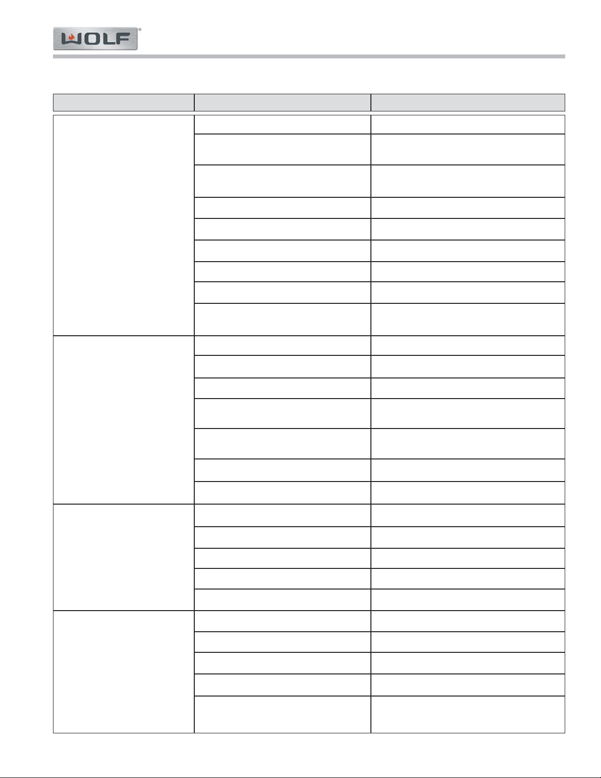
Troubleshooting Guide
Gas Range (GR) Series
Gas Range (GR) Series
5-7
#822634 - Revision A - January, 2013
PROBLEM POSSIBLE CAUSE TEST / ACTION
T. CONSTANT SPARKING AT
FRENCH TOP
U. INTERMITTENT SPARKING
AT FRENCH TOP
V. POOR IGNITION AT
FRENCH TOP
W. NO IGNITION AT FRENCH
TOP
Electrode wired in wrong position at module
Ground wire disconnected at outlet in wall
or unit junction box
Reverse polarity at outlet, power supply or
power cord
Cracked or defective electrode
Defective micro switch at burner valve
Arc at cut or splice in electrode wire
Cable ties on wire too tight
Defective spark module
Arcing at spark module to bracket or unit
chassis
Cracked or defective electrode
Electrode wired in wrong position at module
Arc at cut or splice in electrode wire
Electrode wires touching each other or
metal
Bad connection at molex connector on
spark module
Broken micro switch at burner valve
Defective spark module
Burner head not in position
Partially plugged holes in the burner head
Cracked or damaged electrode or wiring
Check for proper orifice size
Gas pressure
Loose wire connection
Defective electrode
Defective spark module
No power
No gas
Check routing from wiring diagram for model
May have to call an electrician.
May have to call an electrician. May have to
properly wire the power cord to the unit.
Replace electrode
Replace micro switch
Replace electrode wire
Cut tie and replace so wire is loose
Replace spark module
Visually inspect the spark module or bracket for
damage.
Replace electrode
Check routing from wiring diagram for model
Replace electrode wire
Separate cover with sleeving
Determine by continuity check. Repair/replace
molex connector.
Replace micro switch
Replace spark module
Locate per owner’s manual and advise owner
Clear as necessary
Replace electrode or wiring
Check orifice number stamped on orifice
Check gas pressure with a manometer
Check per wiring diagram
Replace electrode
Replace spark module
Check outlet and circuit breaker
Check gas pressure with a manometer
Problems Associated with the French Top
Gas Range (GR) Series
Gas Range (GR) Series
Troubleshooting Guide
5-8
#822634 - Revision A - January, 2013
PROBLEM POSSIBLE CAUSE TEST / ACTION
X. UNEVEN HEAT AT FRENCH
TOP
Y. NOT HOT ENOUGH AT CEN-
TER OF FRENCH TOP
Z. FRENCH TOP FLAME
KEEPS GOING OUT
Unit not level
Flame ring missing
Outer plate installed backwards
Level unit from front to rear and side to side
Place as shown in owner’s manual and advise
customer
Turn outer plate in proper direction
Problems Associated with the French Top
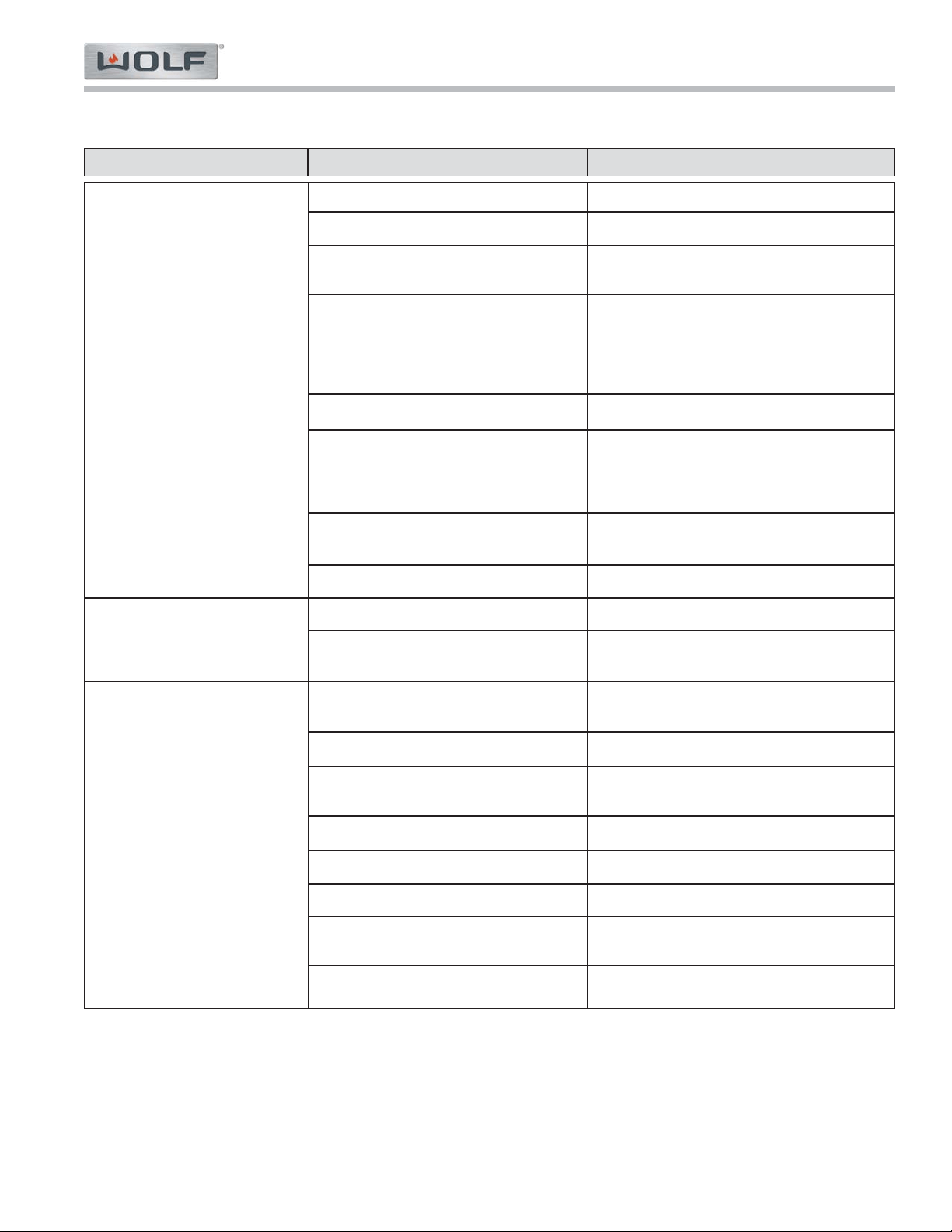
Troubleshooting Guide
Gas Range (GR) Series
Gas Range (GR) Series
5-9
#822634 - Revision A.1 - December, 2016
PROBLEM POSSIBLE CAUSE TEST / ACTION
AA.OVEN BURNER DOES NOT
LIGHT
BB.OVEN BURNER
TEMPERATURE TOO HOT
OR COOL FOR THERMO-
STAT SETTING
CC.DELAYED IGNITION OF
OVEN BURNER
Electrode dirty or defecvtive
Defective Solenoid
Loose or broken connection between com-
ponents
Defective thermostat
No power
No gas
Defective DSI Board
Electrode wire pinched or defective
Thermostat bulb out of position
Oven burner thermostat out of range
Igniter bracket bent
Dirty or Defective Electrode
Bent orifice bracket holder
Defective Solenoid
Defective thermostat
Blockage in venturi or orifice
Defective DSI Board
Electrode wire pinched or defective
Clean or replace electrode
Continuity test. Replace if defective
Check all connections per wiring diagram
• Check continuity at the thermostat, replace
if defective.
• Check for kinked or pinched capillary tube.
Straighten capillary tube or replace thermo-
stat
Check outlet and circuit breaker
• Verify that there is gas to the appliance.
• Check Solenoid.
• Check shut-off valve on manifold to verify it
is in open position.
Perform DSI board troubleshooting procedures
located at end of section 5
Reposition or replace wire
Reposition bulb
Confirm oven temperature is more than ± 25°F
off of setpoint. Replace the oven thermostat.
Straighten and reposition or replace if neces-
sary.
Clean or replace electrode
Straighten so that gas jet is aimed straight
down venturi tube, replace if necessary.
Continuity test. Replace if defective
Replace thermostat
Clear as necessary
Perform DSI board troubleshooting procedures
located at end of section 5
Reposition or replace wire
Problems Associated with the Oven
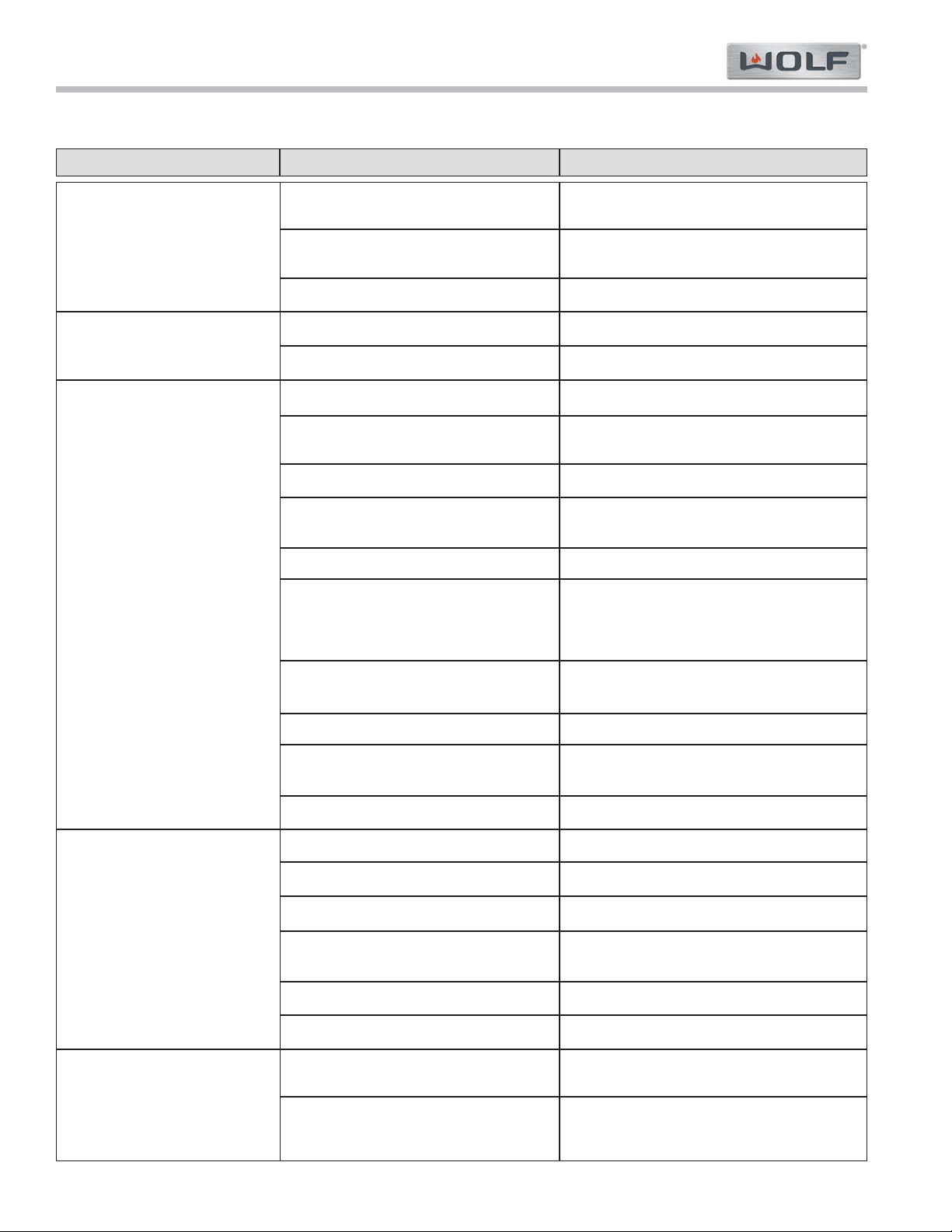
Gas Range (GR) Series
Gas Range (GR) Series
Troubleshooting Guide
5-10
#822634 - Revision A - January, 2013
PROBLEM POSSIBLE CAUSE TEST / ACTION
DD.RUSHING NOISE FROM
OVEN BURNER
EE. YELLOW FLAMES AT OVEN
BURNER
FF. OVEN BROILER BURNER
DOES NOT LIGHT
GG. DELAYED IGNITION OF
OVEN BROILER
HH. RUSHING NOISE FROM
OVEN BROILER BURNER
Bent orifice bracket holder
Oven burner tube pushed too far back
Air shutter out of adjustment
Air shutter out of adjustment
Wrong or dirty orifice
Dirty or defective electrode
Loose or broken connection between com-
ponents
Defective solenoid
Defective thermostat
No power
No gas
Poor electrode position (~ 1/4” (6 mm))
from burner screen
Dirty broiler screen
Defective DSI Board
Electrode wire pinched or defective
Igniter bracket bent
Dirty or defective electrode
Defective solenoid
Bent orifice bracket holder
Blockage in venturi or orifice
Dirty broiler screen
Bent orifice bracket holder
Back Lighting situation
Straighten so that gas jet is aimed straight
down venturi tube, replace if necessary.
Pull burner tube forward so orifice is in burner
tube.
Adjust air shutter
Adjust air shutter
Check orifice size and clean if necessary
Clean or replace electrode.
Check all connections per wiring diagram
Continuity test. Replace if defective
Check continuity at the thermostat and replace
if defective.
Check outlet and circuit breaker
• Verify that there is gas to the appliance.
• Check Solenoid.
• Check shut-off valve on manifold to verify it
is in open position.
Reposition electrode.
Clean screen, or replace broiler.
Perform DSI board troubleshooting procedures
located at end of section 5
Reposition or replace wire
Straighten and position
Clean or replace electrode.
Continuity test. Replace if defective
Straighten so that gas jet is aimed straight
down venturi tube, replace if necessary.
Clear as necessary
Clean screen, or replace broiler.
Straighten so that gas jet is aimed straight
down venturi tube, replace if necessary.
Gas is burning between screens or in box.
Broiler needs to be replaced
Problems Associated with the Oven
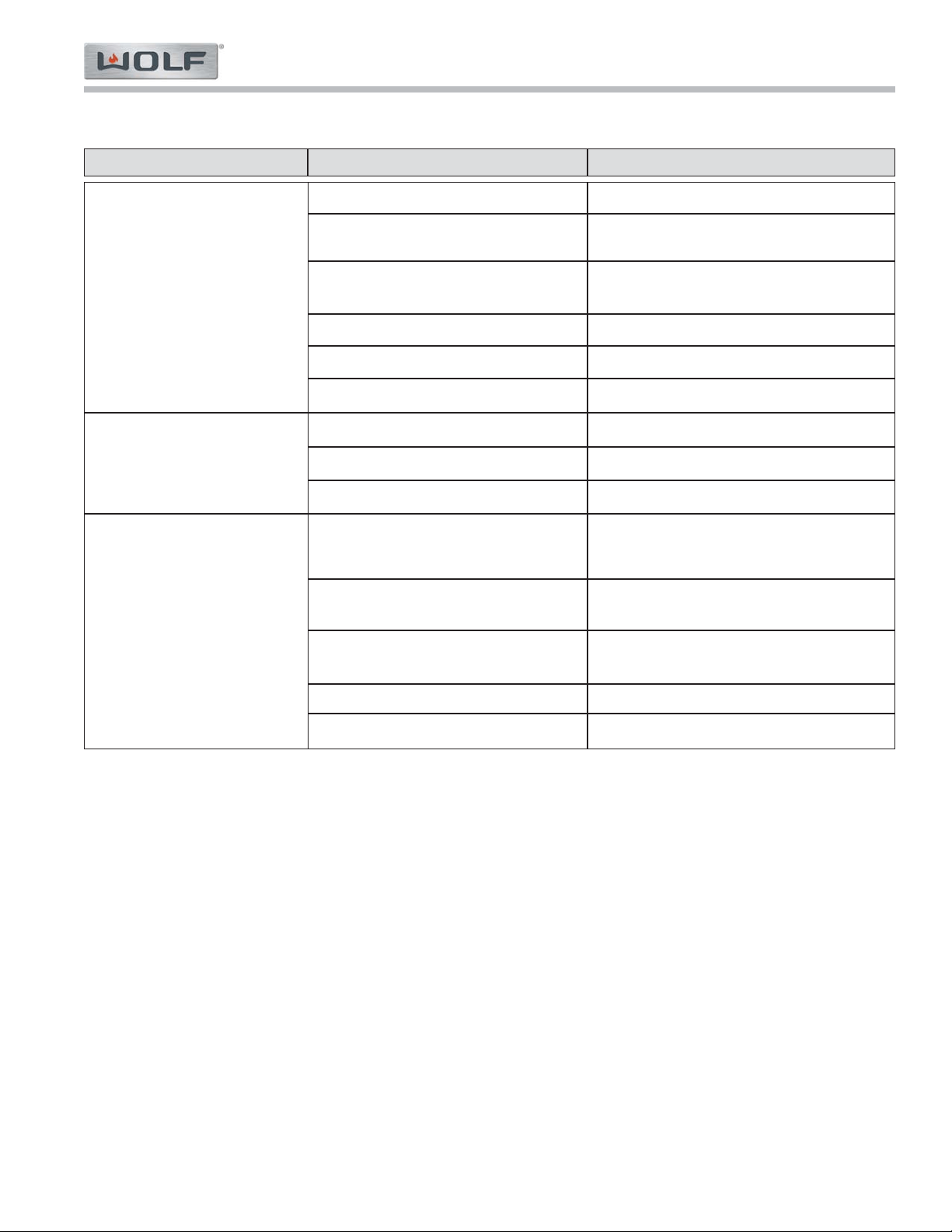
Troubleshooting Guide
Gas Range (GR) Series
Gas Range (GR) Series
5-11
#822634 - Revision A - January, 2013
PROBLEM POSSIBLE CAUSE TEST / ACTION
II. CONVECTION FAN DOES
NOT COME ON WHEN
SWITCH IS TURNED ON
JJ. CONVECTION FAN DOES
NOT SHUT OFF WHEN
DOOR IS OPEN
KK.PROBLEMS ASSOCIATED
WITH THE OVEN LIGHT
Oven broiler is on
Loose connection
Switch does not stay closed
Defective fan motor
Defective fan relay
No Power
Defective fan door switch
Defective fan relay
Defective fan panel switch
Defective light bulb
Loose or disconnected wire connection in
the wiring circuit
Switch does not stay closed
Defective light socket
No power
Fan does not function during broil
Check all components in circuit. See wiring
diagram.
Push and hold switch. If fan works when switch
is being held, replace switch.
Check for continuity and replace if defective
Check for continuity and replace if defective
Check outlet and circuit breaker
Check for continuity and replace if defective
Check for continuity and replace if defective
Check for continuity and replace if defective
Check light bulb and replace if necessary
(NOTE: Halogen lighting, do not touch with
bare hands)
Check for voltage at the light sockets
Push and hold switch. If fan works when switch
is being held, replace switch.
Check continuity of the light socket
Check outlet and circuit breaker
Problems Associated with the Oven
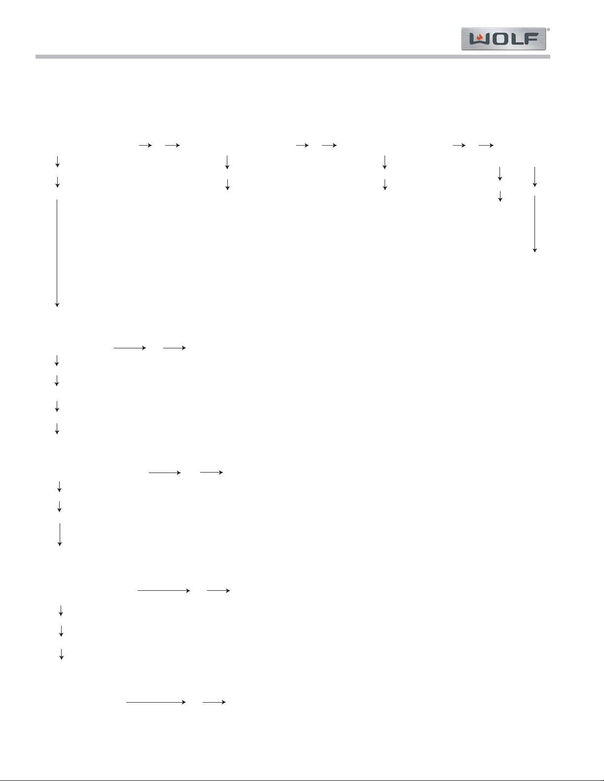
Gas Range (GR) Series
Gas Range (GR) Series
Troubleshooting Guide
5-12
#822634 - Revision A - January, 2013
Step 1.
Testing Supply Voltage for DSI Board
Using a volt/ohm meter set to read AC voltage, place one meter probe to pin 4 and one meter probe to pin 10 on the J1 connector of the DSI board.
With thermostat ON, do you have
115 VAC from Pin 4 to Pin 10?
Yes
Go to step 2
No
Do you have 115 VAC from Pin 1
to Pin 2 on harness connector?
Yes
No
Broken Thermostat or
bad griddle harness
Step 2.
Testing Thermostat
Using a volt/ohm meter set to read AC voltage, place one meter probe to pin 6 and one meter probe to pin 4 on the J1 connector of the DSI board.
Do you have 115 VAC
from Pin 6 to Pin 4?
Yes
Go to step 3
Disconnect power to unit.
Unplug J1 connector at DSI board.
Ohm wires at pin 6 and pin 4 (turn
thermostat ON and OFF
when perform this procedure). If no
ohm reading, check for loose or
defective wire(s), repair/replace if
defective. If wire(s) okay replace
defective thermostat.
Then thermostat
working okay.
Step 3.
Testing DC Voltage for Solenoid Output
Using a volt/ohm meter set to read DC voltage, place one meter probe to pin 1 and one meter probe to pin 2 on the J1 connector of the DSI board.
With thermostat on, do you have
10 VDC from Pin 1 to Pin 2?
No
Go to step 4
Yes
Disconnect power to unit.
Unplug J1 connector at DSI board.
Ohm wires at pin 1 and pin 2. If no
ohm reading, check for loose or
defective wire(s), repair/replace if
defective. If wire(s) okay replace
defective solenoid.
Step 4.
Testing Continuity of P3/GND Wire for DSI Board
Disconnect power to unit. Disconnect wire at P3/GND connection.
Do you have continuity from
P3/GND wire connector to
unit chassis?
Yes
Go to step 5
Repair/replace defective P3/GND
wire.
Step 5.
Testing Continuity of Electrode for DSI Board
Disconnect power to unit. Disconnect wire at P1 connection.
Do you have continuity
from P1 wire connector
to tip of electrode?
No
No
Replace defective DSI Board
Yes
Do you have 115 VAC from Pin 1
to Pin 5 on harness connector?
No
Yes
Check for loose connections
then replace manifold harness
No
Do you have
115 VAC from
L1 to Neutral
Yes
Check for loose
connections then
replace right side
oven harness
Check power cord
or outlet wiring
DSI BOARD TROUBLESHOOTING FLOW CHART (Griddle - French Top - 18” Oven)
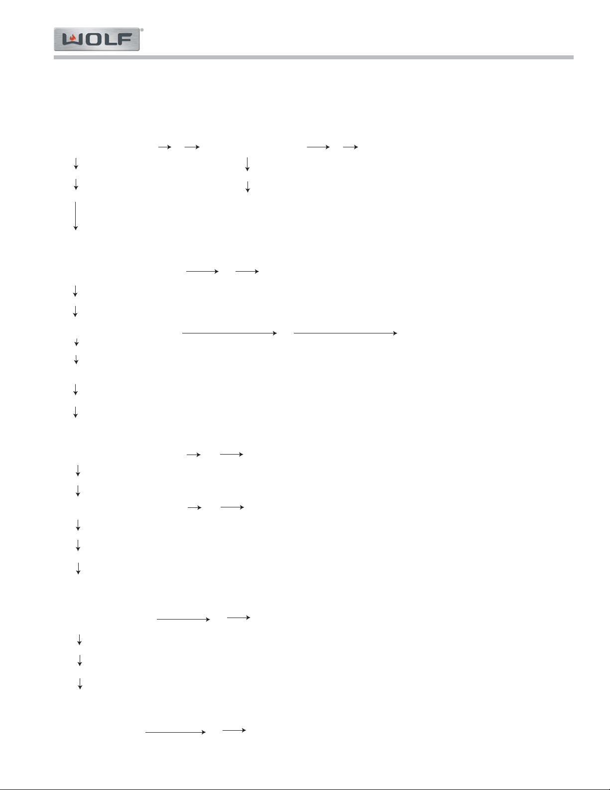
Troubleshooting Guide
Gas Range (GR) Series
Gas Range (GR) Series
5-13
#822634 - Revision A - January, 2013
Step 1.
Testing Supply Voltage for DSI Board
Using a volt/ohm meter set to read AC voltage, place one meter probe to pin 4 and one meter probe to pin 10 on the J1 connector of the DSI board.
With thermostat ON, do you have
115 VAC from Pin 4 to Pin 10?
Yes
Go to step 2
No
Do you have 115 VAC from L1
to Neitral at power inlet?
Yes
Check for loose connections
then replace right side oven
harness
Step 2.
Testing Thermostat
Using a volt/ohm meter set to read AC voltage, place one meter probe to pin 6 and one meter probe to pin 4 on the J1 connector of the DSI board.
Do you have 115 VAC from Pin 6 to
Pin 4 with thermostat turned to bake?
Yes
Go to step 3
Disconnect power to unit.
Unplug J1 connector at DSI board.
Check for continuity across contacts
on oven thermostat pins 6 & 10
with thermostat turned to bake.
Replace thermostat if open.
Then thermostat
working okay.
Step 3.
Testing DC Voltage for Solenoid Output
Using a volt/ohm meter set to read DC voltage, place one meter probe to pin 1 and one meter probe to pin 2 on the J1 connector of the DSI board.
With thermostat turned to bake, do
you have 10 VDC from Pin 1 to Pin 2?
No
Go to step 4
Yes
Disconnect power to unit. Unplug J1 connector at DSI board. Ohm wires at pin 1
and pin 2. If no continuity, check for loose or defective wire(s), repair/replace if
defective. If wire(s) okay replace defective bake solenoid.
Step 4.
Testing Continuity of P3/GND Wire for DSI Board
Disconnect power to unit. Disconnect wire at P3/GND connection.
Do you have continuity from
P3/GND wire connector to
unit chassis?
Yes
Go to step 5
Repair/replace defective P3/GND
wire.
Step 5.
Testing Continuity of Electrode for DSI Board
Disconnect power to unit. Disconnect wire at P1 connection.
Do you have continuity
from P1 wire connector
to tip of electrode?
No
No
Replace defective DSI Board
Yes
Check power cord
or outlet wiring
No
Do you have 115 VAC from Pin 7 to
Pin 4 with thermostat turned to broil?
Disconnect power to unit.
Unplug J1 connector at DSI board.
Check for continuity across contacts
on oven thermostat pins 6 & 10
with thermostat turned to bake.
Replace thermostat if open.
No
Yes
With thermostat turned to bake, do
you have 10 VDC from Pin 2 to Pin 3?
Yes
Disconnect power to unit. Unplug J1 connector at DSI board. Ohm wires at Pins 2
and 3. If no continuity, check for loose or defective wire(s), repair/replace if
defective. If wire(s) OK, replace defective broil solenoid.
No
DSI BOARD TROUBLESHOOTING FLOW CHART (30” and 36” Oven)
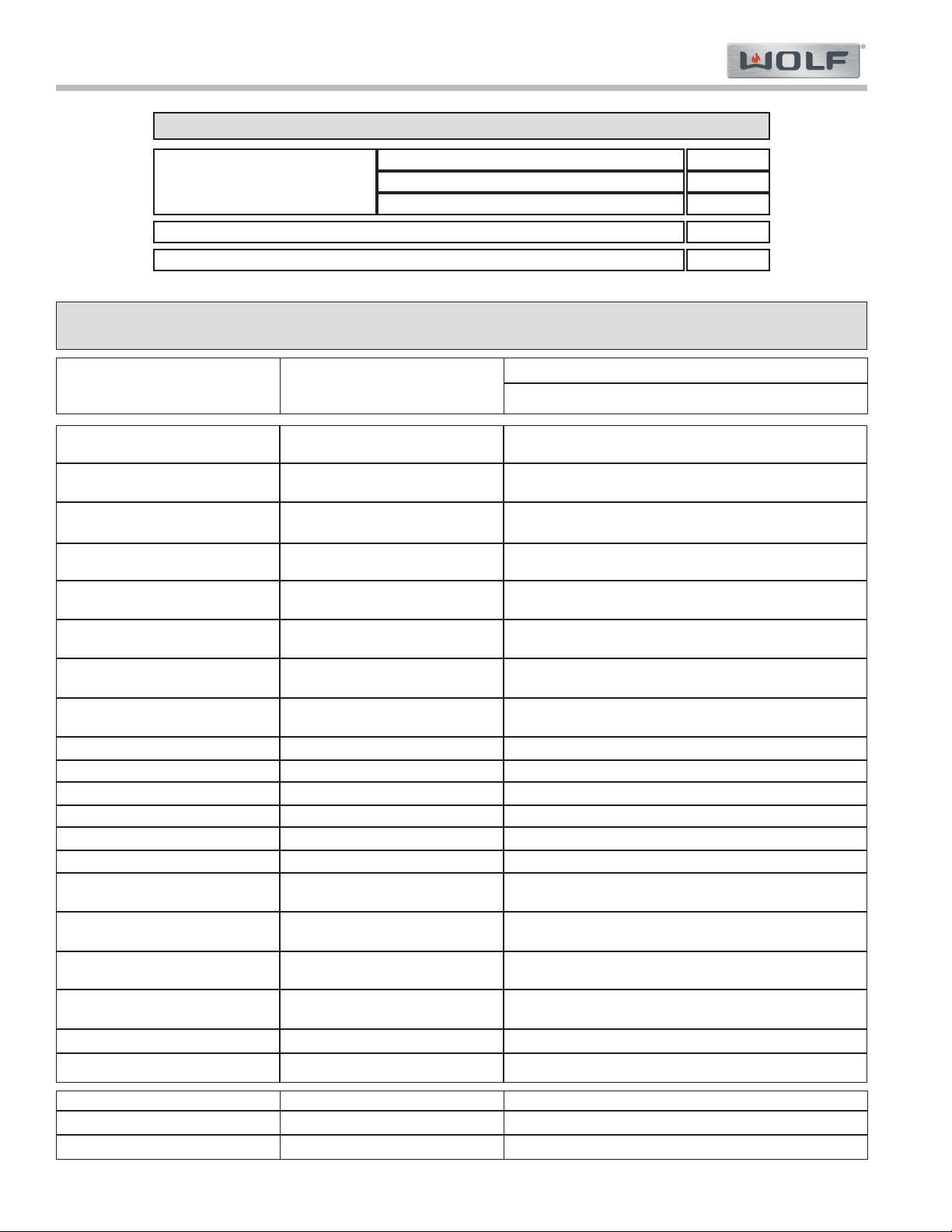
6-2
#822634 - Revision A - January, 2013
Gas Range (GR) Series
Gas Range (GR) Series
Technical Data
GAS PRESSURE
Natural Gas Minimum
Liquid Propane Minimum
Natural Gas and Liquid Propane Maximum
Gas Supply Line Pressure
Liquid Propane Manifold Pressure, with Standard Orifice
14” WC
Natural GasManifold Pressure, with Standard Orifice
7” WC
11” WC
10” WC
5” WC
Part Description
Orifice Size
Part # Size Marking
Part Number
Burner Valve, 15K, Nat
Burner Valve, 15K, LP
Burner Valve, 9.2K, Nat
Burner Valve, 9.2K, LP
Orifice Holder, 15K, Nat
Orifice Holder, 15K, LP
Orifice Holder, 9.2K, Nat
Orifice Holder, 9.2K, LP
Orifice Holder, FT, Nat
Orifice Holder, FT, LP
Orifice Char IR, Nat
Orifice Char IR, LP
Orifice Griddle IR, Nat
Orifice Griddle IR, LP
Orifice Oven Burner Tube, Nat
Large Oven
Oven Burner Tube, LP
Large Oven
Orifice Oven Burner Tube, Nat
Small 18” Oven
Oven Burner Tube, LP
Small 18” Oven
Oven Broil, Nat
Bake safety valve
Simmer 804128 .62 mm 62
Main 809495 .67 mm 67
Simmer 809493 .43 mm 43
Main 809493 .43 mm 43
Simmer 809494 .50 mm 50
Main 800054 .54 mm 54
Simmer 801322 .33 mm 33
Main 800893 .34 mm 34
Simmer 809485 .79 mm 79
Main 809484 1.80 mm 180
Simmer 809479 .47 mm 47
Main 809743 1.17 mm 117
Simmer 809482 .65 mm 65
Main 809481 1.40 mm 140
Simmer 809477 .41 mm 41
Main 809476 .93 mm 93
Main 809484 1.80 mm 180
Main 809743 1.17 mm L
800837 0.070 in 50
801011 0.043 in 57
800838 0.067in 51
801011 0.043 in 57
36
1.65
48
55
48
128
808016
808017
808014
808015
809781
809752
808000
808001
808006
808007
Orifice Quick Reference Orifice Chart (Domestic Units)
Part Description
Resistance
Part Number
Broil safety valve
812707
812707
208 Ω ±10%
208 Ω ±10%
Oven Broil, LP 822331 820692 1.28 mm
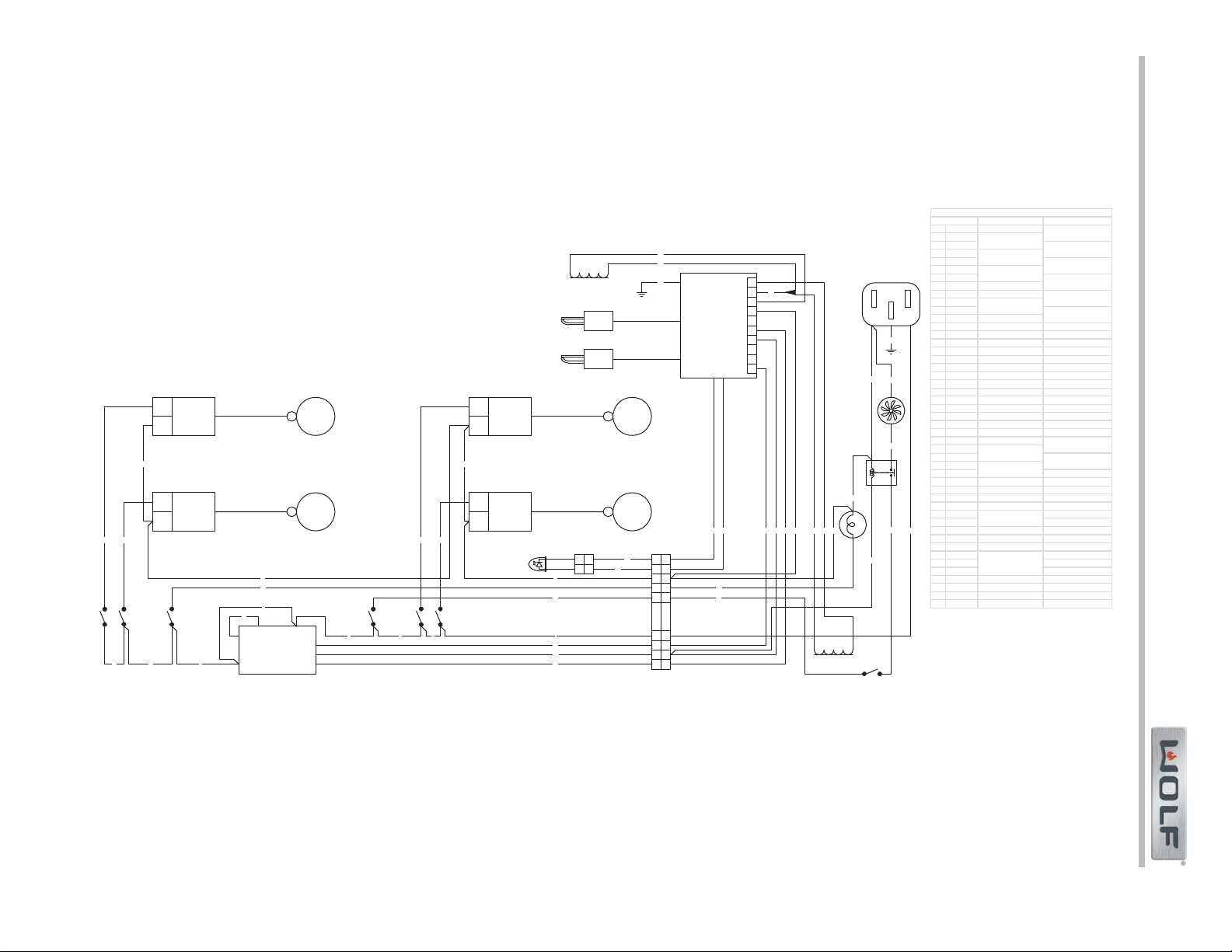
Gas Range (GR) Series
Gas Range (GR) Series
Wiring Diagrams
7-2
#822634 - Revision A - January, 2013
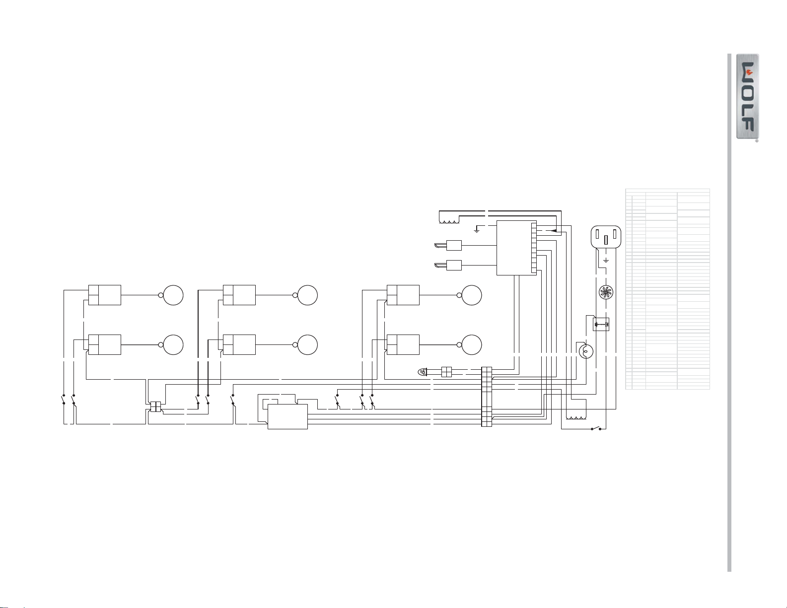
Wiring Diagrams
Gas Range (GR) Series
Gas Range (GR) Series
7-3
#822634 - Revision A - January, 2013
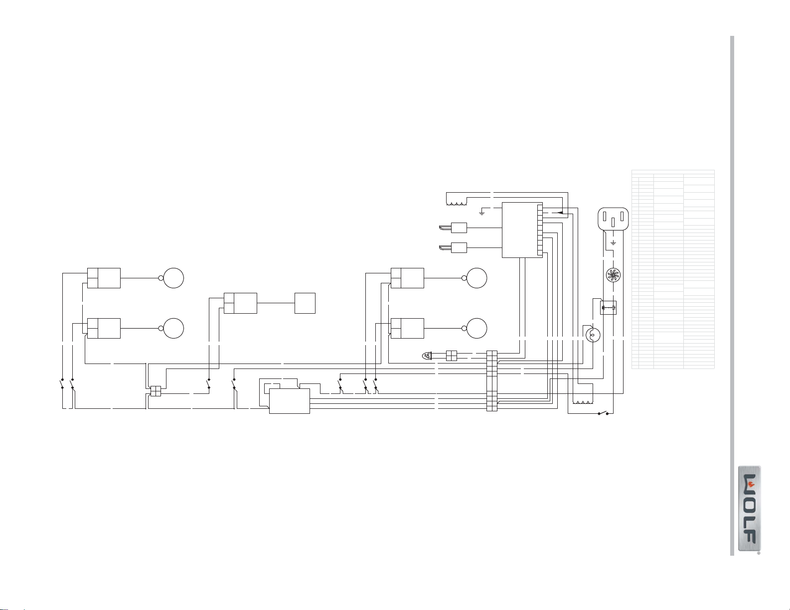
Gas Range (GR) Series
Gas Range (GR) Series
Wiring Diagrams
7-4
#822634 - Revision A - January, 2013
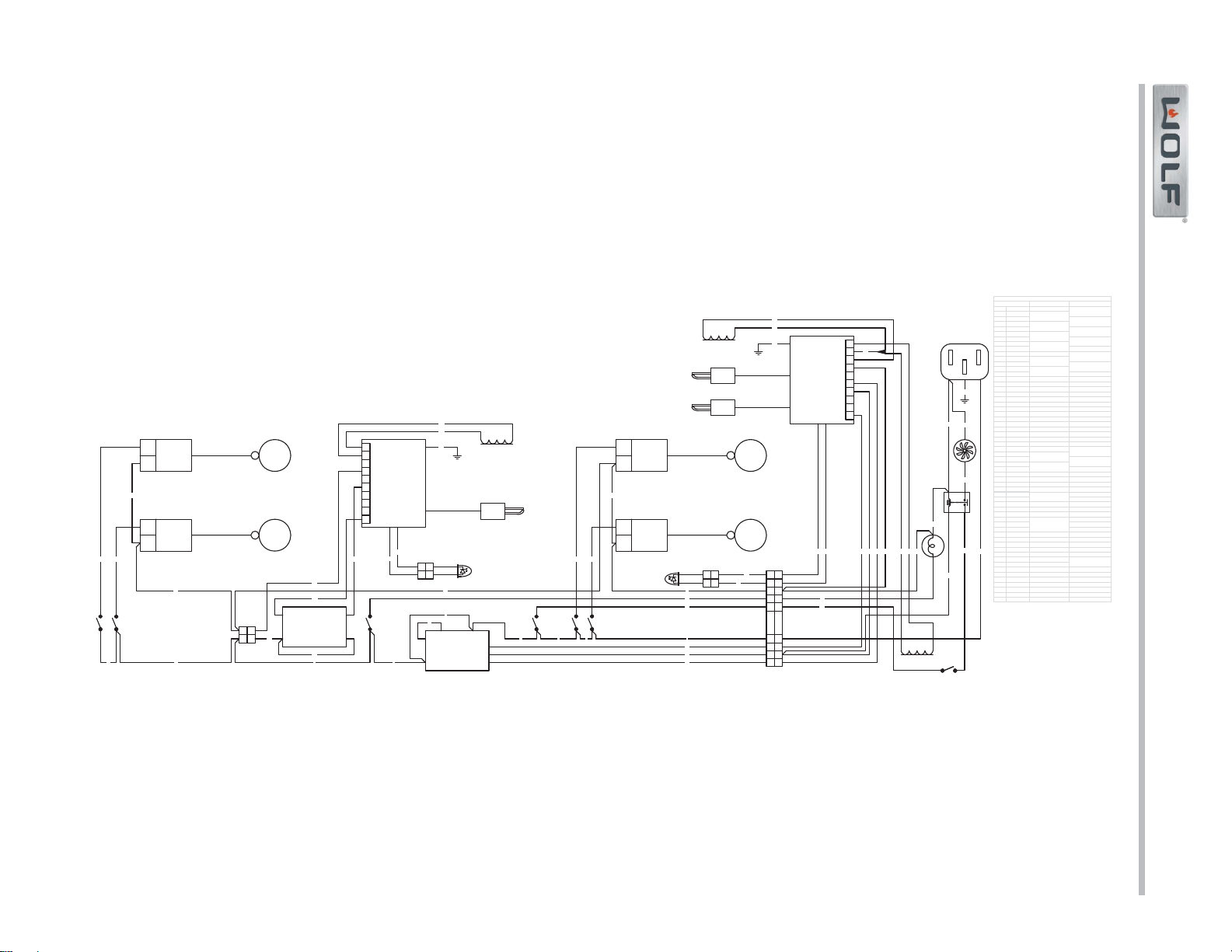
Wiring Diagrams
Gas Range (GR) Series
Gas Range (GR) Series
7-5
#822634 - Revision A - January, 2013
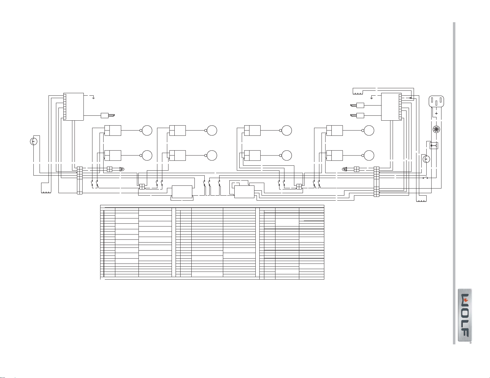
Gas Range (GR) Series
Gas Range (GR) Series
Wiring Diagrams
7-6
#822634 - Revision A - January, 2013
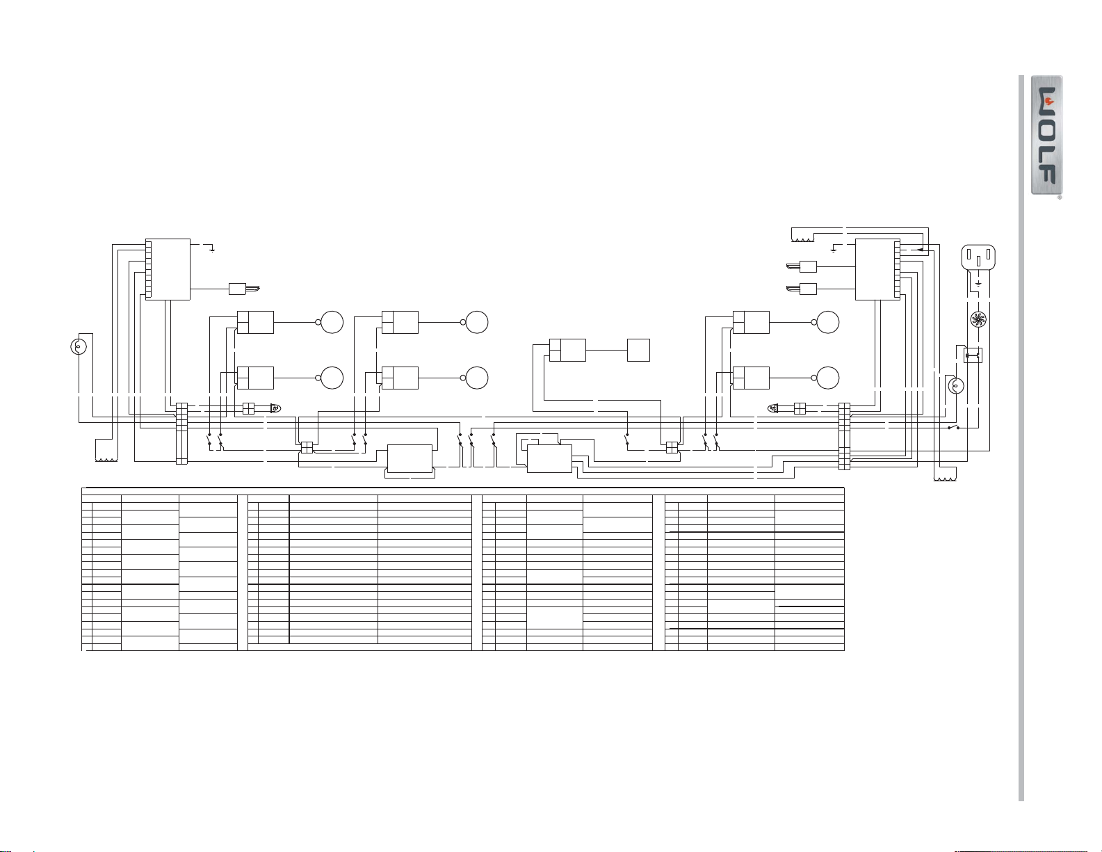
Wiring Diagrams
Gas Range (GR) Series
Gas Range (GR) Series
7-7
#822634 - Revision A - January, 2013
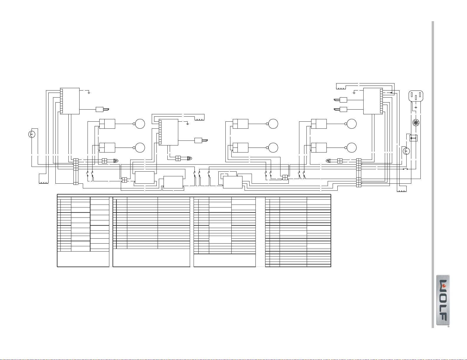
Gas Range (GR) Series
Gas Range (GR) Series
Wiring Diagrams
7-8
#822634 - Revision A - January, 2013
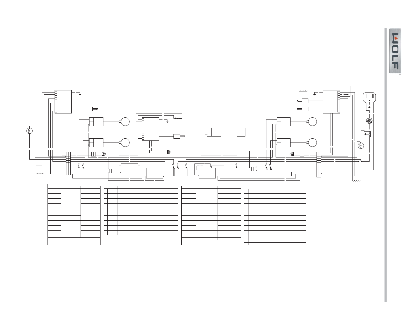
Wiring Diagrams
Gas Range (GR) Series
Gas Range (GR) Series
7-9
#822634 - Revision A - January, 2013
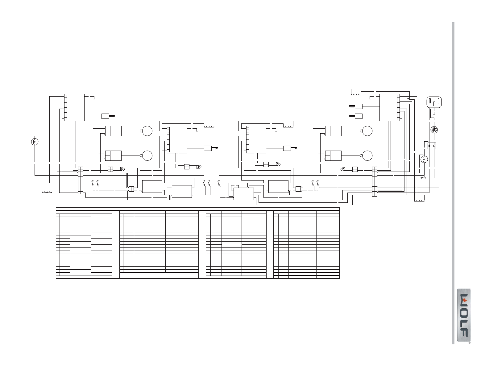
Gas Range (GR) Series
Gas Range (GR) Series
Wiring Diagrams
7-10
#822634 - Revision A - January, 2013
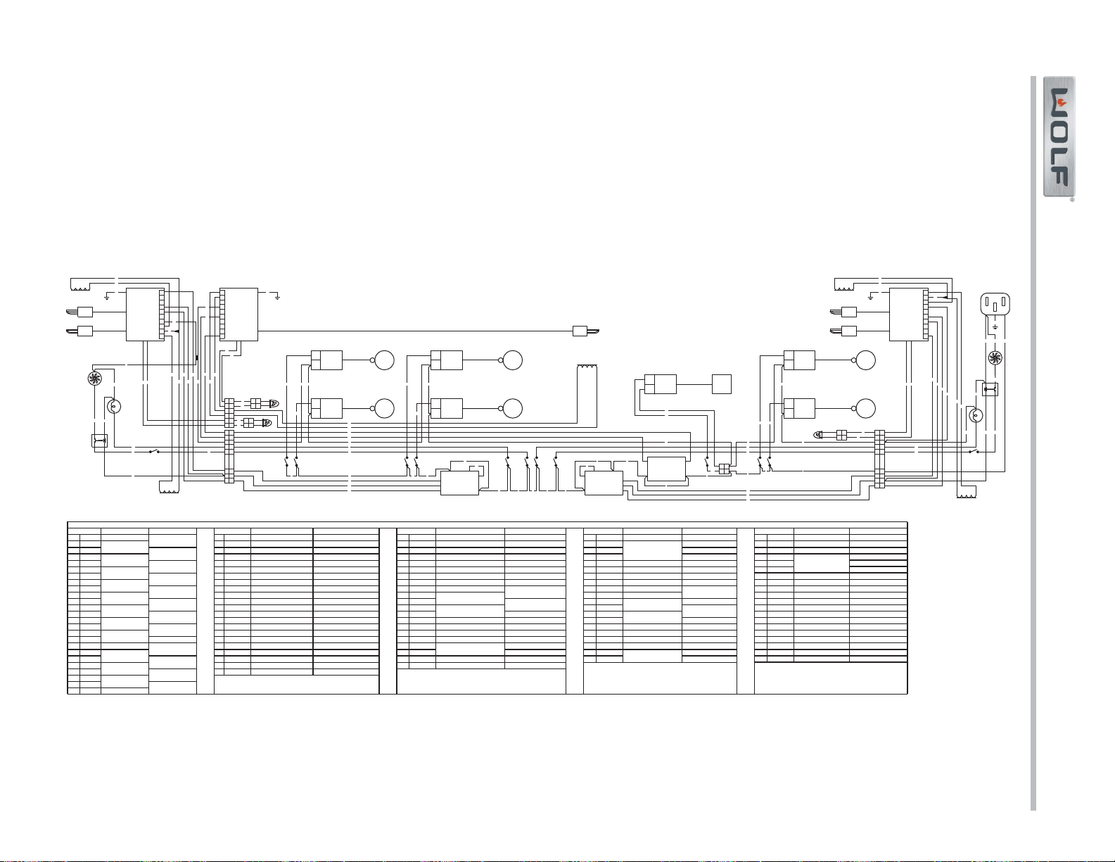
Wiring Diagrams
Gas Range (GR) Series
Gas Range (GR) Series
7-11
#822634 - Revision A - January, 2013
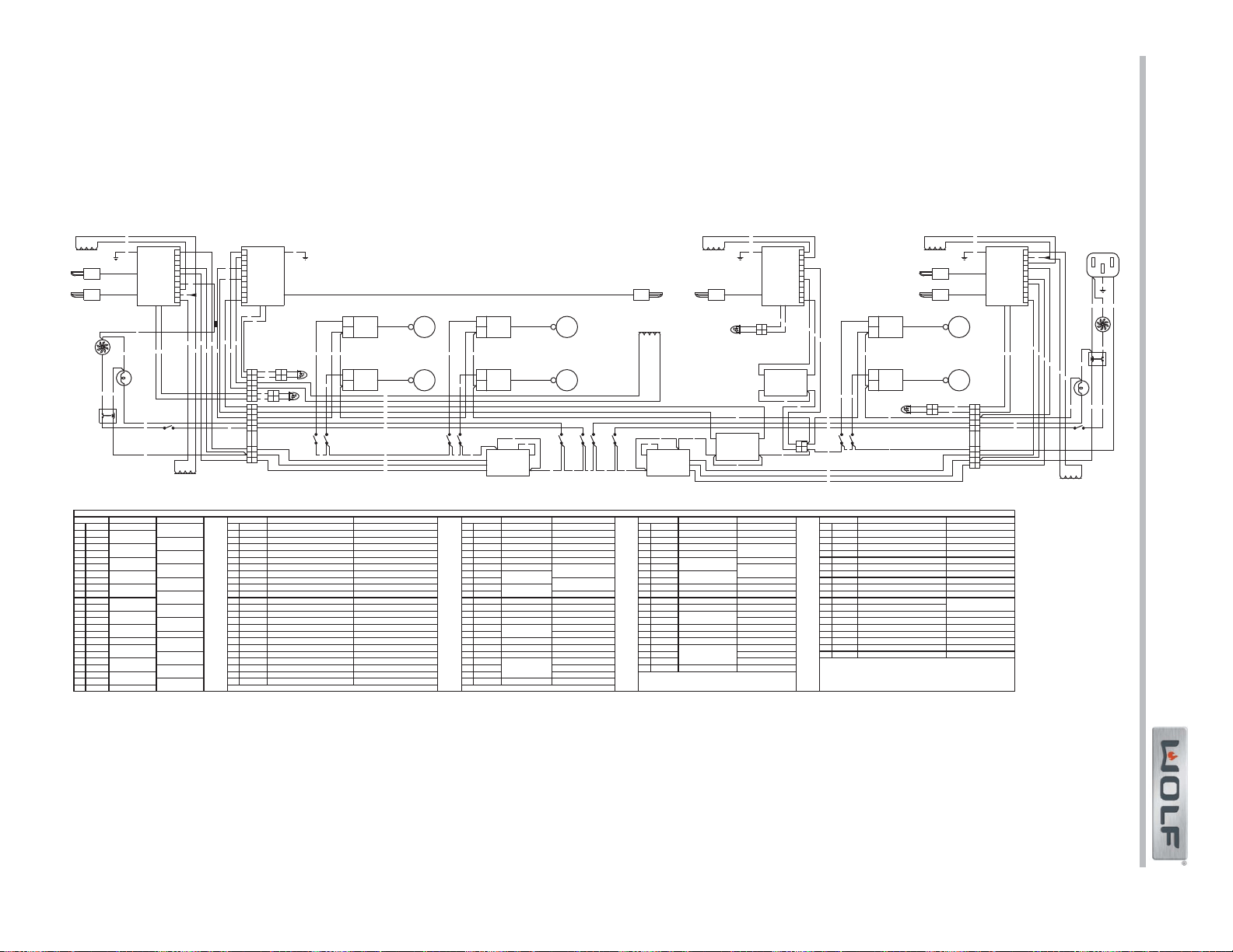
Gas Range (GR) Series
Gas Range (GR) Series
Wiring Diagrams
7-12
#822634 - Revision A - January, 2013
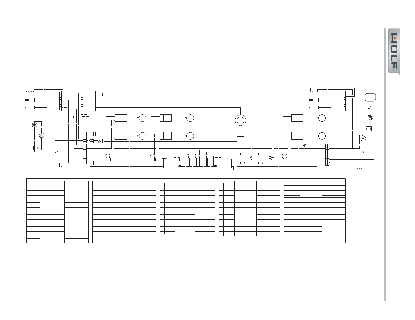
Wiring Diagrams
Gas Range (GR) Series
Gas Range (GR) Series
7-13
#822634 - Revision A - January, 2013