TM
PATENT PENDING
WELDER
Model No. 831.159360
Serial No.
The serial number can be found in the
location shown below. Write the serial
number in the space above.
Serial Number Decal
F" x E: R C i _._, E:
Eq3, U I P M E N T
HELPLINEI
1-800-736-6879
USER'S MANUAL
a_AUTION-
SEARS
BEARB, ROEBUCK AND CO., HOFFMAN ESTATES, IL 60179
TABLE OF CONTENTS
IMPORTANT PRECAUTIONS ............................................................. 2
BEFORE YOU BEGIN ................................................................... 3
ASSEMBLY ........................................................................... 4
ADJUSTMENT ........................................................................ 19
TROUBLE-SHOOTING AND MAINTENANCE ......... ....................................... 22
CABLE DIAGRAM ..................................................................... 23
ORDERING REPLACEMENT PARTS ................................................. Back Cover
FULL 90 DAY WARRANTY ....................................................... Back Cover
Note: An EXPLODED DRAWING/PART LIST and a PART IDENTIFICATION CHART are attached to the center
of this manual, Remove the EXPLODED DRAWING/PART LIST and the PART IDENTIFICATION CHART before
beginning assembly.
7. The be
time.
o Alwya stand on a foot plate when perform-
1, Ing an exeralee th_ _ld _use the home
9Ymay stern to tip. _, _
11.
Never release the press arm, butterfly arms,
squst arm, leg lever, tat bar, or nylon strap
while weights are raised, The weights will fall
with great force.
12. Make sure that the cables remain onthe pul-
leys at all times. If the cables bind while you
are exercising, stop Immediately and make
sure that the cables are on all of the pulleys.
13. Always disconnect the let bar from the home
_oymsystem when oerformlno an exerciQe
that does not use the let bar.
2
BEFORE YOU BEGIN
Thank you for selecting the WELDER= PRO 9625
Home Gym System. The versatile PRO 9625 is
designed to develop every major muscle group of the
body. Whether your goal is a shapely figure, dramatic
muscle size and strength, or a healthier cardiovascular
system, the PRO 9625 will help you to achieve the
specific results you want.
For your benefit, read this manual carefully before
using the WELDER= PRO 9625 Home Gym System.
If you have additional questions, please call our toll-
free HELPLINE at 1-800-736-6879, Monday through
Saturday, 7 a.m, until 7 p.m. Central Time (excluding
holidays). To help us assist you, please note the prod-
uct model number and serial number before calling.
The model number is 831.159360. The serial number
can be found on a decal attached to the WELDER=
PRO 9625 (see the front cover of this manual).
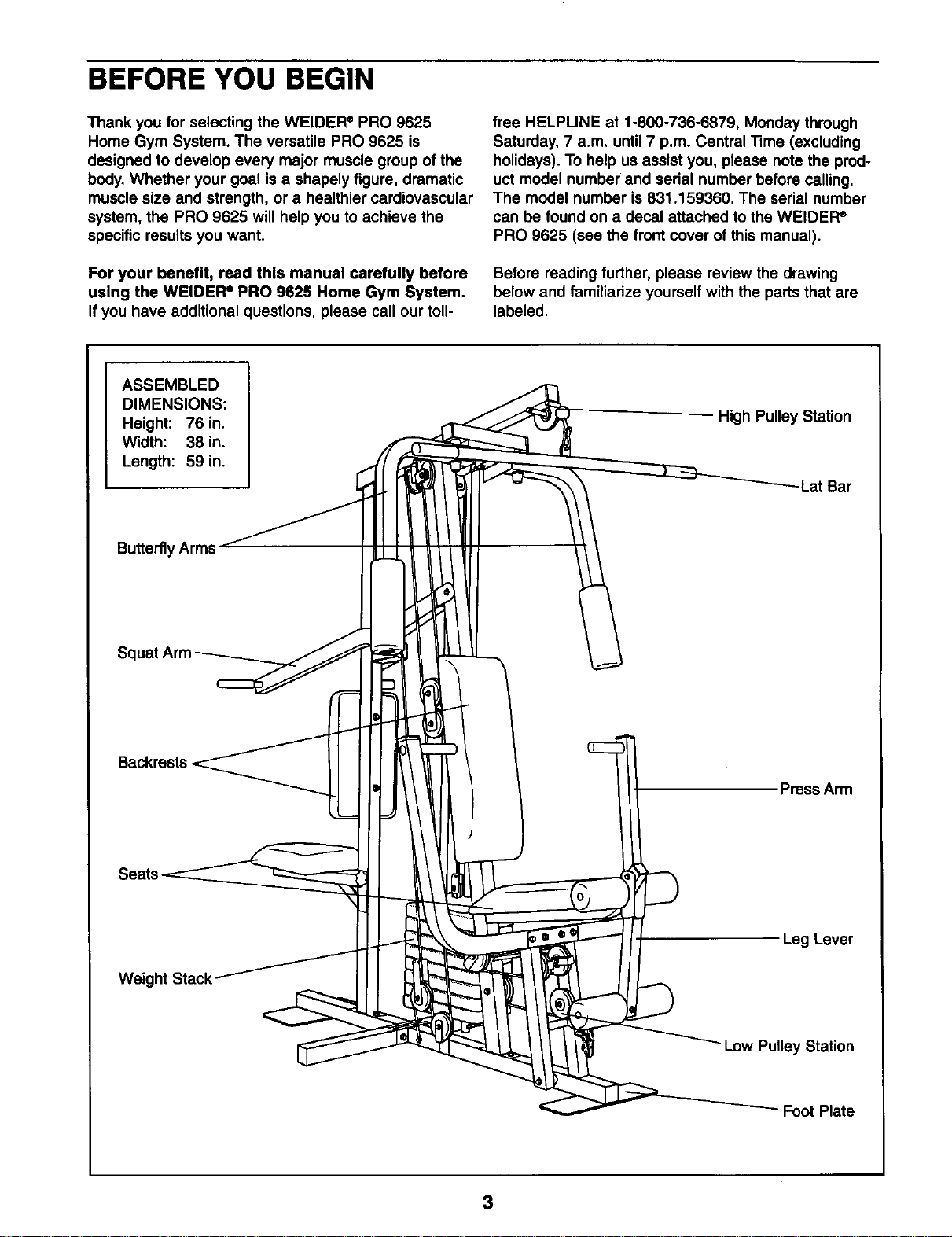
Before reading further, please review the drawing
below and familiarize yourself with the parts that are
labeled.
ASSEMBLED
DIMENSIONS:
Height: 76 in.
Width: 38 in.
Length: 59 in.
High Pulley Station
Lat Bar
Butterfly Arms
Squat
Weight
Press Arm
Leg Lever
Low Pulley Station
- Foot Plate
3
ASSEMBLY
Before beginning assembly, carefully read the
following Information and Instructions:"
• Place all parts of the home gym system in a
cleared area and remove the packing materials;
do not dispose of the packing materials until
assembly is completed.
• The assembly is divided into four stages: 1)
frame assembly, 2) press, squat, and butterfly
arm assembly, 3) cable and pulley assembly, and
4) seat and backrest assembly. The hardware for
each stage is packaged separately.
• Wait until you begin each assembly stage to open
that parts bag.
• For help identi_ing the small parL_used in
assembly, use the PART IDENTIFICATION
CHART located In the center of this manual.
Note: Some smal_parts may have been pre*
attached for shipping. If a part is not in the parts
bag, check to see if it has been pre-attashed.
• As you assemble the home gym system, be sure
that all parts are oriented as shown in the
drawings.
• "Tightenall parts as you assemble them, unless
Instructed to do otherwise.
THE FOLLOWING TOOLS (NOT INCLUDED) ARE
REQUIRED FOR ASSEMBLY:
• Two (2) adjustable wrenches
• One (1) standard screwdriver
• One (1) phillips screwdriver
• One (1) rubber mallet
• Lubdcent, such as grease or petroleum jelly,
and soapy water will also be needed.
Assembly will be more convenient ifyou have the
following tools: A socket set, a set of open-end or
closed-end wrenches, or a set of ratchet wrenches.
_i_ _¸_¸¸ _!
UL
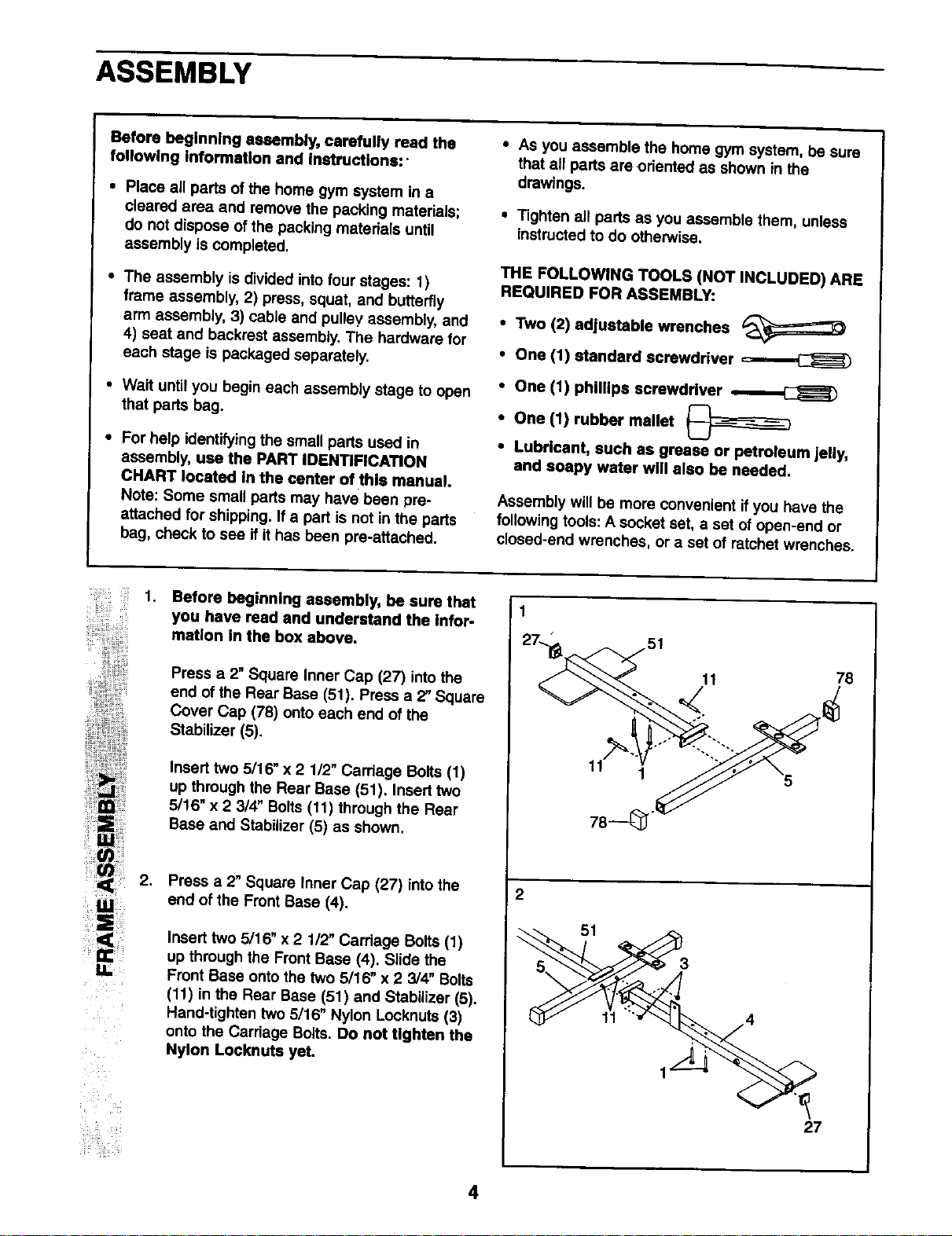
1.
Before beginning assembly, be sure that
you have read and understand the Infor-
mation In the box above.
Press a 2" Square Inner Cap (27) intothe
end of the Rear Base (51). Press a 2" Square
Cover Cap (78) onto each end of the
Stabilizer (5).
Insert two 5/16" x 2 1/2" Carriage Bolts (1)
up through the Rear Base (51). Insert two
5/16" x 2 3/4" Bolts(11) through the Rear
Base and Stabilizer (5) as shown,
2.
Press a 2" Square Inner Cap (27) intothe
end of the Front Base (4).
Insert two 5/16" x 2 112"Carriage Bolts (1)
up through the Front Base (4), Slide the
Front Base ontothe two 5/16" x 2 3/4" Bolts
(11) in the Rear Base (51) and Stabilizer (5).
Hand-tighten two 5/16" Nylon Locknuts (3)
onto the Carriage Bolts. Do not tighten the
Nylon Locknuts yet.
2
11 78
<
11' 1
3
11 ":'__. 4
27
4
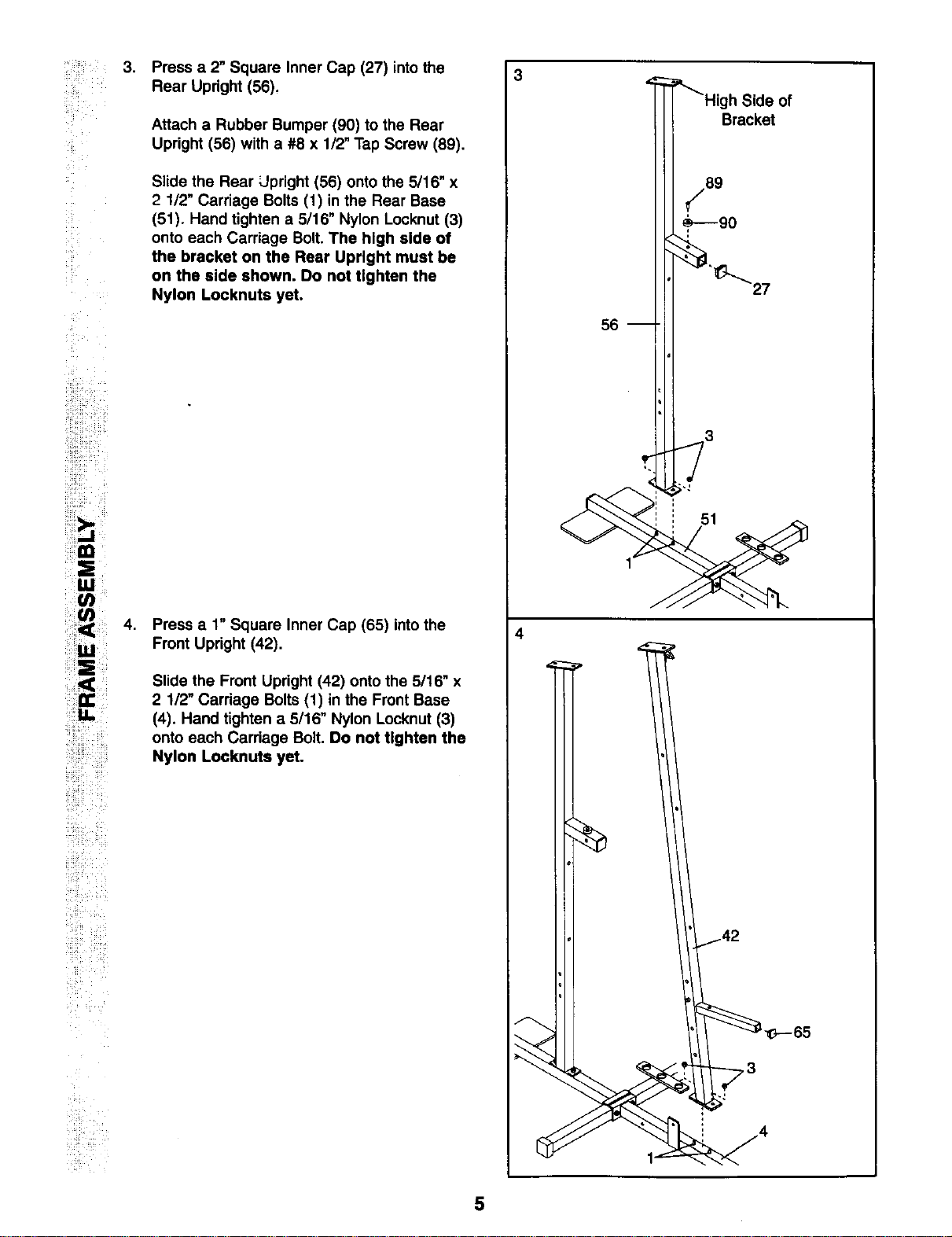
3. Press a 2" Square Inner Cap (27)into the 3
Rear Upright (56),
!_IM i
!
!i_i!t,_ 4.
_iii_ i__i_i_
!iiilil
Attach a Rubber Bumper (90) to the Rear
Upright (56) with a #8 x 112"Tap Screw (89).
Slide the Rear Llpright (56) onto the 5/16" x
2 1/2" Carriage Bolts (1) in the Rear Base
(51). Hand tighten a 5/16" Nylon Locknut (3)
onto each Carriage Bolt. The high side of
the bracket on the Rear Upright must be
on the side shown. Do not tighten the
Nylon Locknuts yet.
Press a 1" Square Inner Cap (65) into the
Front Upright (42).
Slide the Front Upright (42) onto the 5/16" x
2 1/2" Carriage Bolts (1) in the Front Base
(4). Hand tighten a 5/16" Nylon Locknut (3)
onto each Cardage Bolt. Do not tighten the
Nylon Locknute yet.
4
h Side of
Bracket
27
56
3
;-J
51
5
!iii i _ii_i_ i_i
ii_ii_ i_:_i_i!iiii_
ill _:_!_iiii_i
!i!!_i!__i!_ii_
__iii_ii_ii_
_i_ _ i_i
,
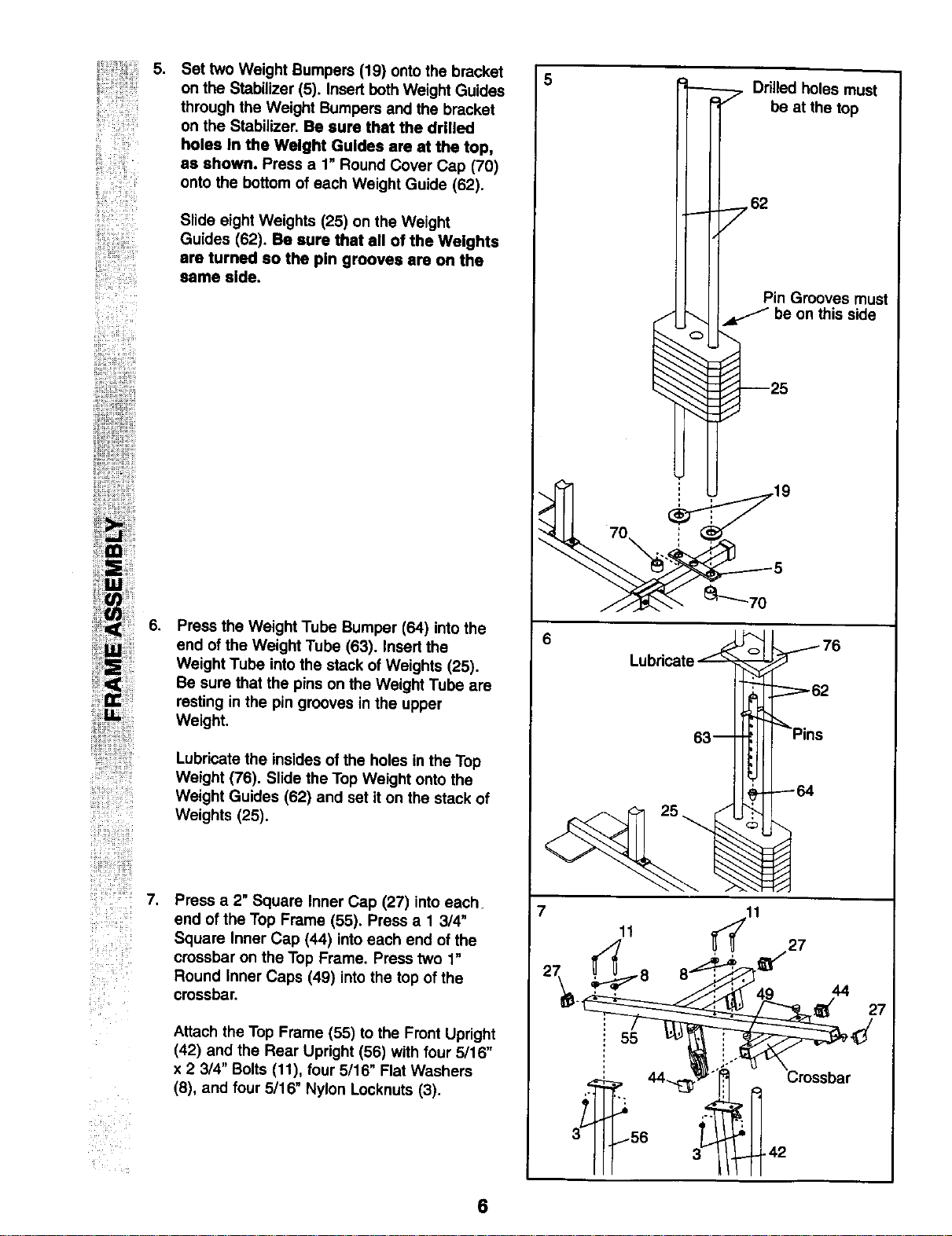
Set two Weight Bumpers (19) onto the bracket
on the Stabilizer (5). Insert bothWeight Guides
through the Weight Bumpers and the bracket
on the Stabilizer. Be sure that the drilled
holes In the Weight Guides are at the top,
as shown. Press a 1" Round Cover Cap (70)
onto the bottom of each Weight Guide (62).
Slide eight Weights (25) on the Weight
Guides (62). Be sure that all of the Weights
are turned so the pin grooves are on the
same side.
.
Press the Weight Tube Bumper (64) intothe
end of the Weight Tube (63). Insert the
Weight Tube into the stack of Weights (25).
Be sure that the pins on the Weight Tube are
resting in the pin grooves in the upper
Weight.
Lubricate the insides of the holes in the Top
Weight (76). Slide the Top Weight onto the
Weight Guides (62) and set it on the stack of
Weights (25).
.
Press a 2" Square Inner Cap (27) into each.
end of the Top Frame (55). Press a 1 3/4"
Square Inner Cap (44) into each end of the
crossbar on the Top Frame. Press two 1"
Round Inner Caps (49) into the top of the
crossbar.
Attach the Top Frame (55) to the Front Upright
(42) and the Rear Upright (56) with four 5/16"
x 2 3/4" Bolts (11), four 5/16" Flat Washe_'s
(8), and four 5/16" Nylon Locknuts (3).
5
6
7
Drilled holes must
7 be at the top
7 62
Pin Grooves must
be on this side
11
55
6
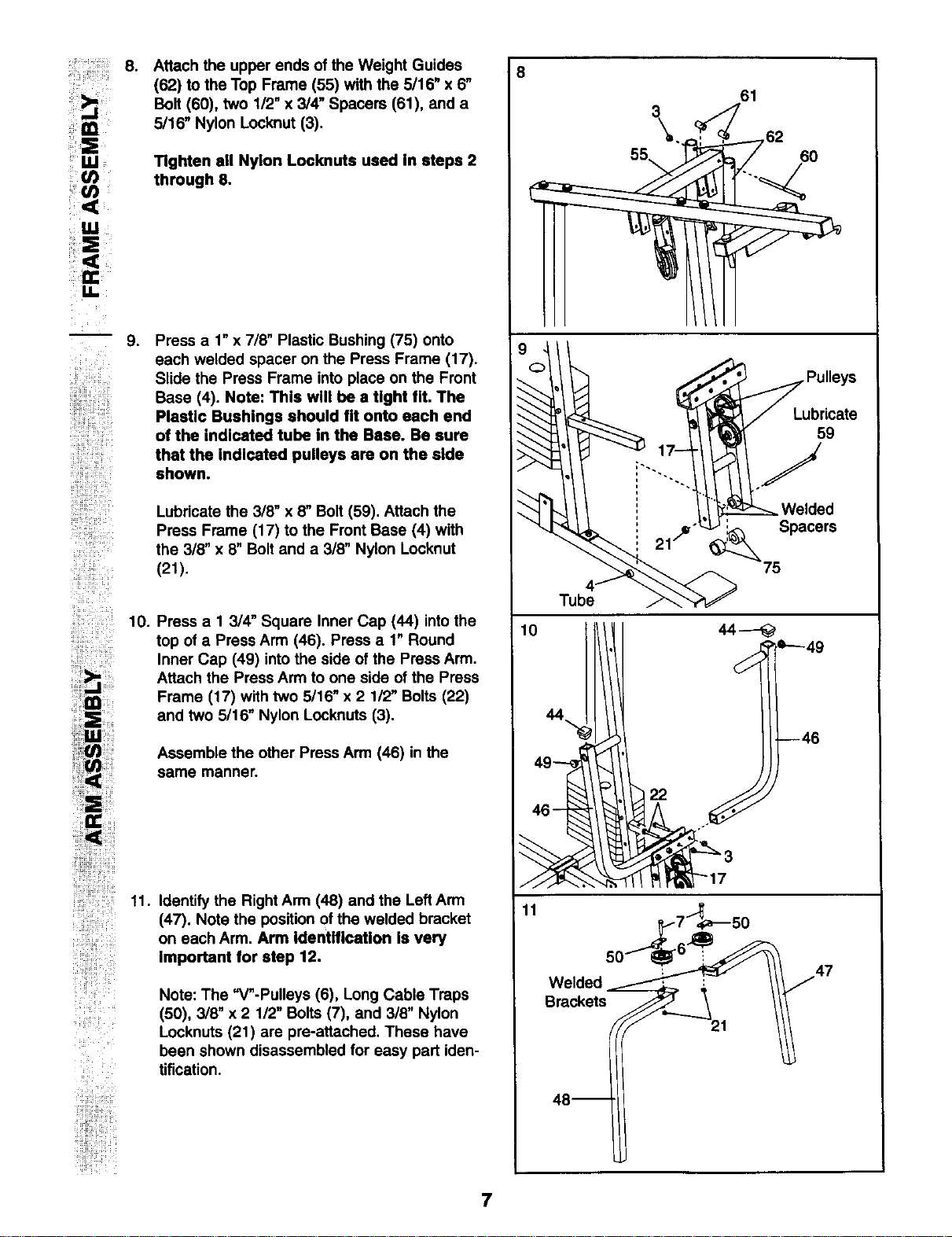
:: 8. Attach the upper ends of the Weight Guides
(62) to the Top Frame (55) with the 5/16" x 6"
Bolt (60), two 1/2" x 3/4" Spacers (61), and a
5/16" Nylon Locknut (3).
i ¸ Ul
Tighten all Nylon Locknute used In steps 2
through 6.
,
i!!!iiiiiiii!iii!!il110
Press a 1" x 7/8" Plastic Bushing (75) onto
each welded spacer on the Press Frame (17).
Slide the Press Frame into place on the Front
Base (4). Note: This will be a fight fit. The
Plastic Bushings should fit onto each end
of the indicated tube in the Base. Be sure
that the indicated pulleys are on the side
shown.
Lubricate the 3/8" x 8" Bolt (59). Attach the
Press Frame (17) to the Front Base (4) with
the 3/8" x 8" Bolt and a 3/8" Nylon Locknut
(21).
Press a I 3/4" Square Inner Cap (44) intothe
top of a Press Arm (46). Press a 1" Round
Inner Cap (49) into the side of the Press Arm.
Attach the Press Arm to one side of the Press
Frame (17) with two 5116" x 2 1/2" Bolts (22)
and two 5116"Nylon Locknuts (3).
Assemble the other Press Arm (46) in the
same manner.
ii!iiiiiiiiii_ili_i;iiiiii!_
i!!iiiiiiii!!iiliil11.
iiiiliili
ii ¸
Identify the Right Arm (48) and the LeftArm
(47). Note the position Of the welded bracket
on each Arm. Arm Identification Is very
Important for step 12.
Note: The "V"-Pulleys (6), Long Cable Traps
(50), 3/8" x 2 1/2" Bolts (7), and 3/8" Nylon
Locknuts (21) are pre-attached. These have
been shown disassembled for easy part iden-
tification.
i;!;i_i!i:ii;iii!
8
61
3 . ,
Tube
10
11
_7_-_50
We,ded // 47
Brackets_ '_21
7
ii ¸
{ i ¸¸ :=i
i ¸
:
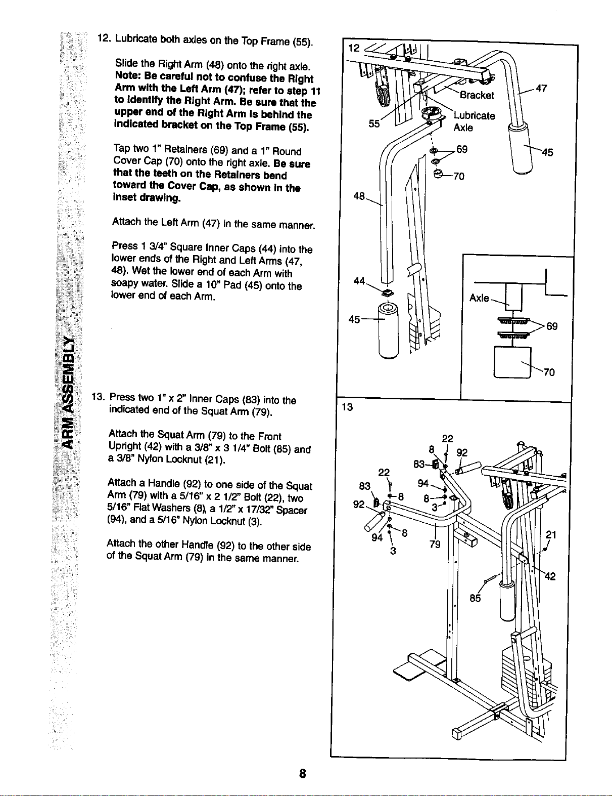
12. Lubricate both axles on the Top Frame (55),
Slide the Right Arm (48) onto the right axle.
Note: Be careful not to confuse the Right
Arm with the Left Arm (47); refer to step 11
to Identify the Right Arm. Be sure that the
upper end of the Right Arm is behind the
indicated bracket on the Top Frame (55).
Tap two 1" Retainers (69) and a 1" Round
Cover Cap (70) onto the right axle. Be sure
that the teeth on the Retainers bend
toward the Cover Cap, as shown In the
Inset drawing.
Attach the Lef_Arm (47) in the same manner.
Press 1 3/4" Square Inner Caps (44) into the
lower ends of the Right and LeftArms (47,
48). Wet the lower end of each Arm with
soapy water. Slide a 10" Pad (45) onto the
lower end of each Arm,
13.
Press two 1"x 2" Inner Caps (83) intothe
indicated end of the Squat Arm (79).
Attach the Squat Arm (79) to the Front
Upright (42) with a 3/8" x 3 1/4" Bolt (85) and
a 3/8" Nylon Locknut (21).
Attach a Handle (92) to one side of the Squat
Arm (79) with a 5/16" x 2 1/2" Bolt (22), two
5/16" Rat Washers (8_ a 1/2"x 17132"Spacer
(94), and a 5/16" Nylon Locknut (3).
Attach the other Handle (92) to the other side
of the Squat Arm (79) in the same manner.
13
22
92
22
83
-8
94
3
8
ii_ _i _
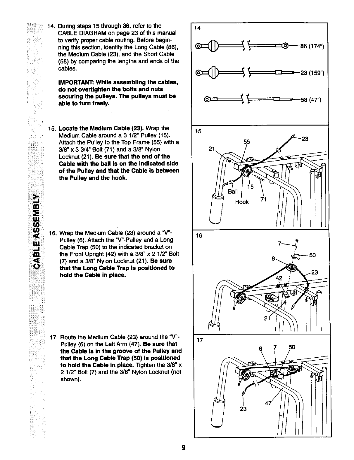
During steps 15 through 36, refer to the
CABLE DIAGRAM on page 23 of this manual
to verify proper cable routing. Before begin-
ning this section, identify the Long Cable (86),
the Medium Cable (23), and the Short Cable
(58) by comparing the lengths and ends of the
cables.
IMPORTANT: While assembling the cables,
do not overtlghten the bolts and nuts
securing the pulleys. The pulleys must be
able to turn freely.
15. Locate the Medium Cable (23). Wrap the
Medium Cable around a 3 1/2" Pulley (15).
Attach the Pulley to the Top Frame (55) with a
3/8" x 3 3/4" Bolt (71) and a 3/8" Nylon
Locknut (21). Be sure that the end of the
Cable with the ball Is on the indicated side
....... of the Pulley and that the Cable is between
the Pulley and the hook.
iiiiiili_ii!1 16. Wrap the Medium Cable (23) around a =V"-
Pulley (6). Attach the "V_-Pulley and a Long
ii!!!!i<lCi!
Cable Trap (50) to the indicated bracket on
the Front Upright (42) with a 3/8" x 2 1/2" Bolt
(7) and a 3/8" Nylon Locknut (21). Be sure
that the Long Cable Trap Is positioned to
hold the Cable In place.
iii!ili!!! i!iiiii
17. Route the Medium Cable (23) around the =V"-
Pulley (6) on the Left Arm (47). Be sure that
the Cable Is In the groove of the Pulley and
that the Long Cable Trap (50) Is positioned
to hold the Cable In place. Tighten the 3/8" x
2 112"Bolt (7) and the 3/8" Nylon Locknut (not
shown).
14
_ _ '' _-86 (174")
:_ _ _-_-,_23 (159")
:L u , 58 (47")
15
16
17
21_
;5 ._'-23
Hook 71 //
7---q
6 7 50
47
23
9
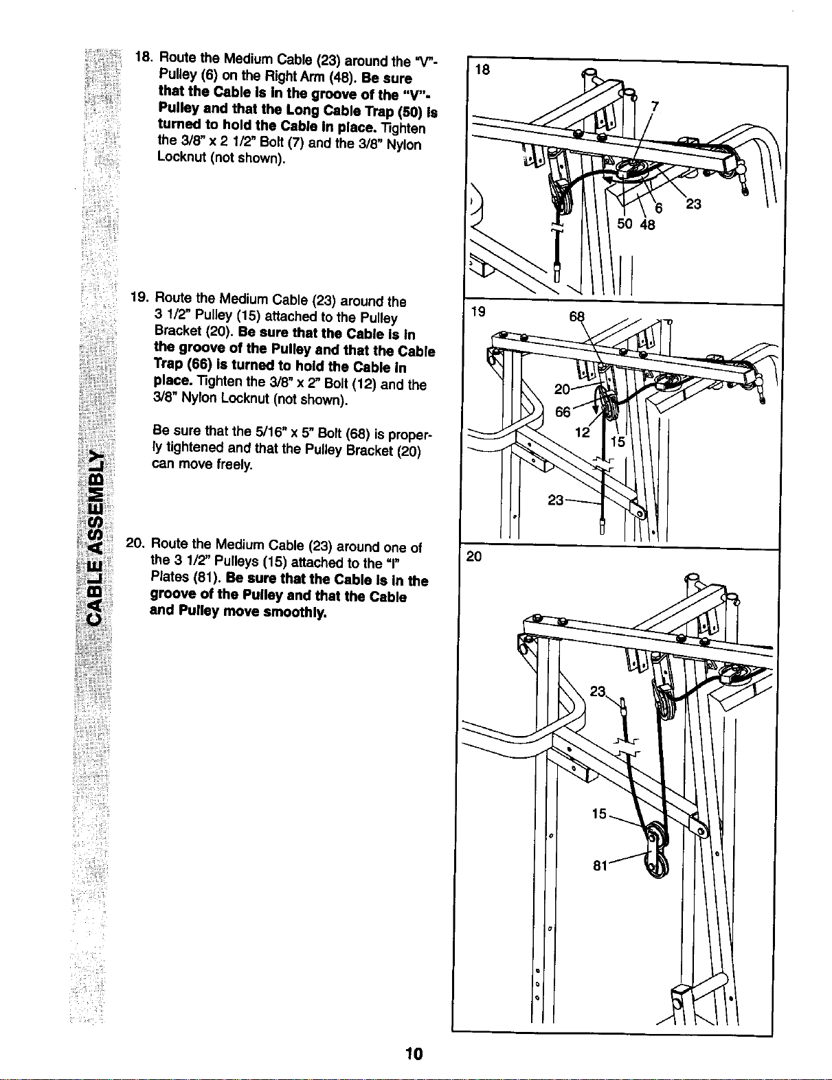
18. Route the Medium Cable (23) around the =V-
Pulley (6) on the Right Arm (48). Be sure
that the Cable Is In the groove of the "V"-
Pulley and that the Long Cable Trap (50) Is
turned to hold the Cable In place, "13ghten
the 3/8" x 2 1/2, Bolt (7) and the 3/8" Nylon
Locknut (not shown).
19.
Route the Medium Cable (23) around the
3 1/2, Pulley (15) attached to the Pulley
Bracket (20). Be sure that the Cable Is In
the groove of the Pulley and that the Cable
Trap (66) is turned to hold the Cable in
place. Tighten the 3/8" x 2" Bolt (12) and the
3/8" Nylon Locknut (not shown).
Be sure that the 5/16" x 5" Bolt (68) is proper-
ly tightened and that the Pulley Bracket (20)
can move freely.
20. Route the Medium Cable (23) around one of
the 3 1/2" Pulleys (15) attached to the =1"
Plates (81). Be sure that the Cable is in the
groove of the Pulley and that the Cable
and Pulley move smoothly,
18
7
48
2O
10
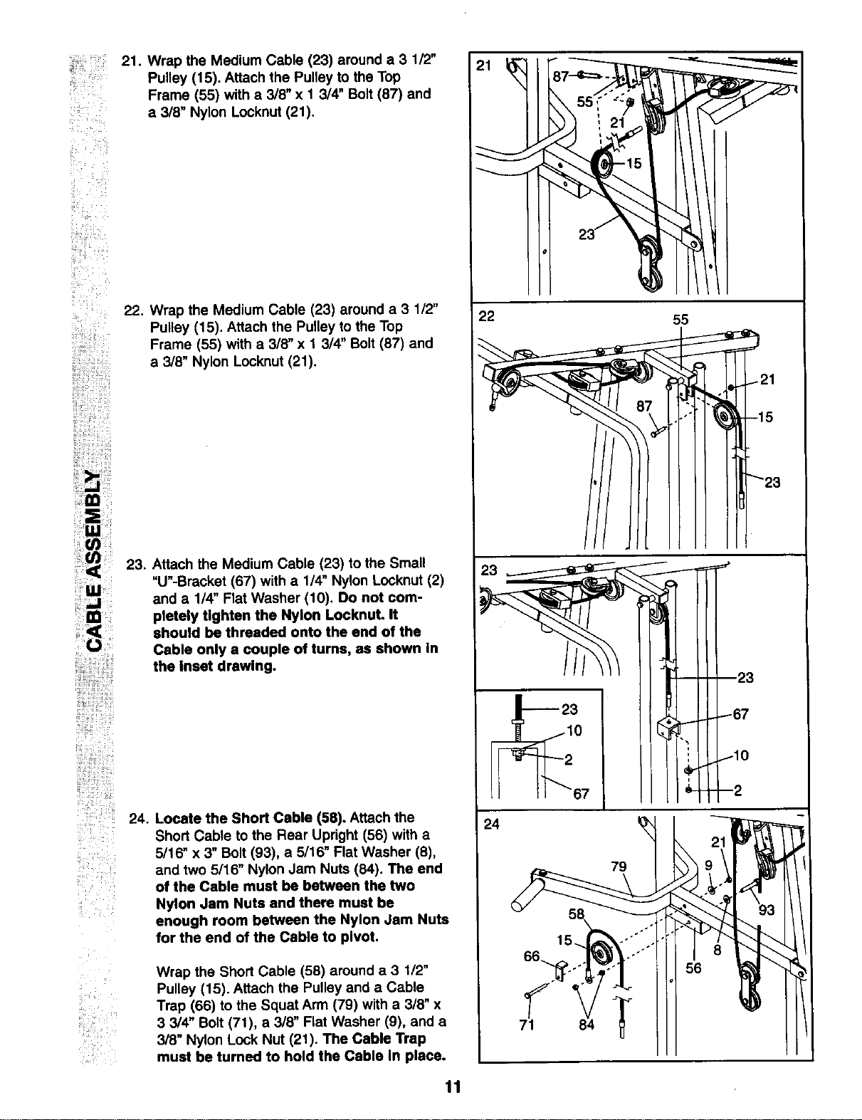
: 21. Wrap the Medium Cable (23) around a 3 1/2"
Pulley (15). Attach the Pulley to the Top
Frame (55) with a 3/8" x 1 3/4" Bolt (87) and
.... Nyl t (21)a 3/8" on Locknu .
ii ¸¸
!_!i_!i__
Lii
22. Wrap the Medium Cable (23) around a 3 1/2"
Pulley (15). Attach the Pulley to the Top
Frame (55) with a 3/8" x 1 314" Bolt (87) and
a 3/8" Nylon Locknut (21).
i!_i ii ii ii
il i!il ¸ i i!ii;
!i¸_:i
i_iiii!il!_i!i_!ii_i_
!!ili!!!ii!iiii_ii!i_i_i:i_:i
23, Attach the Medium Cable (23) to the Small
"U"-Bracket (67) with a 1/4" Nylon Locknut (2)
and a 1/4" Flat Washer (10), Do not com-
pletely tighten the Nylon Locknut. It
should be threaded onto the end of the
Cable only a couple of turns, as shown In
the Inset drawing.
24. Locate the Short Cable (58). Attach the
Short Cable to the Rear Upright (56) with a
5/16" x 3" Bolt (93), a 5/16" Flat Washer (8),
and two 5/16" Nylon Jam Nuts (84). The end
of the Cable must be between the two
Nylon Jam Nuts and there must be
enough room between the Nylon Jam Nuts
for the end of the Cable to pivot.
Wrap the Short Cable (58) around a 3 112"
Pulley (15). Attach the Pulley and a Cable
Trap (66) to the Squat Arm (79) with a 3/8" x
3 3/4" Bolt (71), a 3/8" Flat Washer (9), and a
3/8" Nylon Lock Nut (21). The Cable Trap
must be turned to hold the Cable In place.
22 55
21
15
23
23
79
56
11
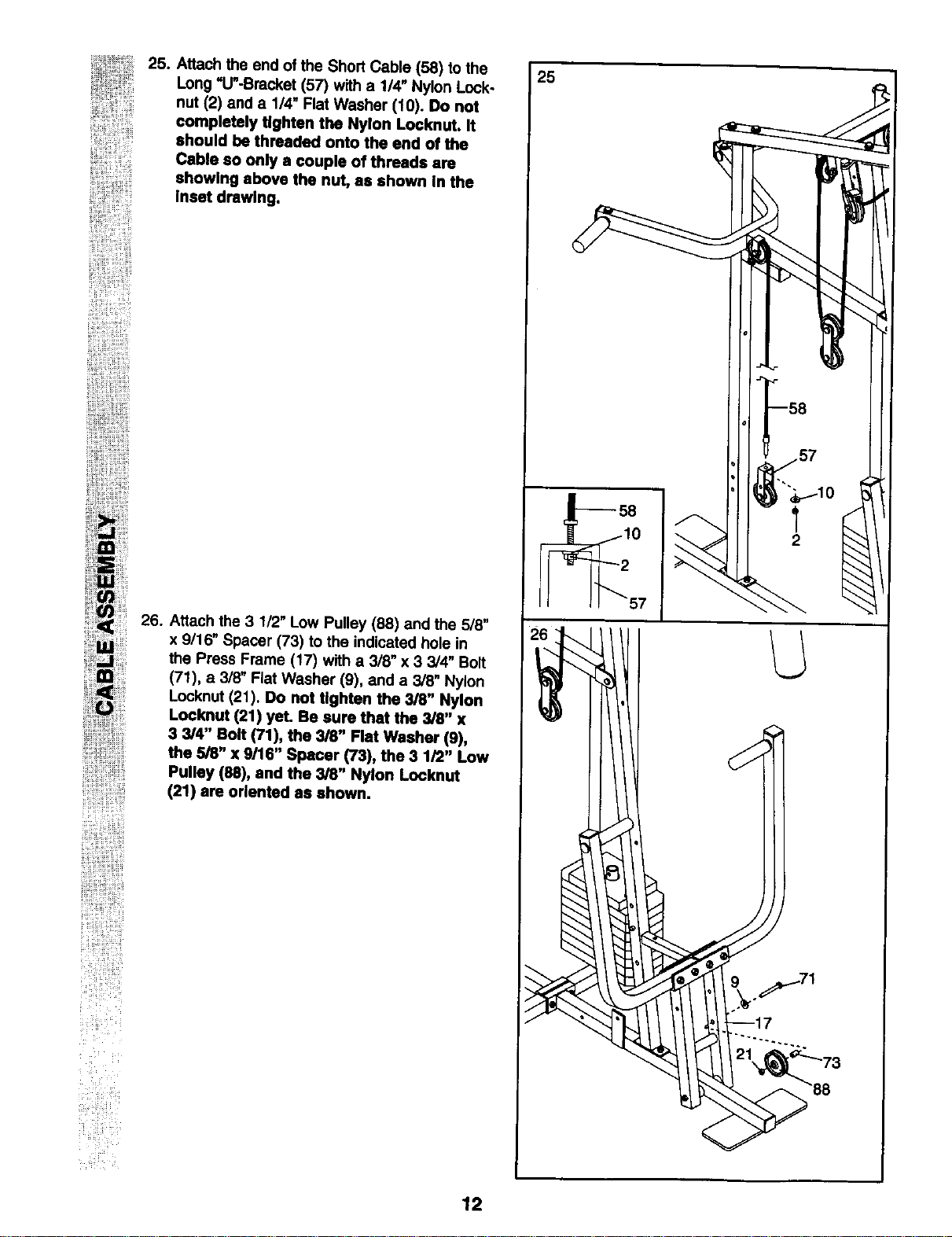
25. 25
Attach the end of the Short Cable (58) to the
Long "U"-Bracket (57) with a 1/4" Nylon Lock-
nut (2) and a 1/4" Flat Washer (10). Do not
completely tighten the Nylon Locknut. It
should be threaded onto the end of the
Cable so only a couple of threads are
showing above the nut, as shown In the
Inset drawlng.
26. Attach the 3 1/2" Low Pulley (88) and the 5/8"
x 9/16" Spacer (73) to the indicated hole in
the Press Frame (17) with a 3/8" x 3 3/4" Bolt
(71), a 3/8" Flat Washer (9), and a 3/8" Nylon
Locknut (21). Do not tighten the 3/8" Nylon
Locknut (21) yet. Be sure that the 3/8" x
3 3/4" Bolt (71), the 3/8" Rat Washer (9),
the 5/8" x 9/16" Spacer (73), the 3 1/2" Low
Pulley (88), and the 3/8" Nylon Locknut
(21) am oriented as shown.
2
12
27,
!i!!!_i!ii_I_!_
!ii_ _
_ii_iii!i i_
i!i_i!!iiiiiiiiiii_!iiii!iiill
ii!iiiiii_iii!_i_i!i!ii!iii_il
30
!ii_ii_i_ _ill_
_iii!i! _ i
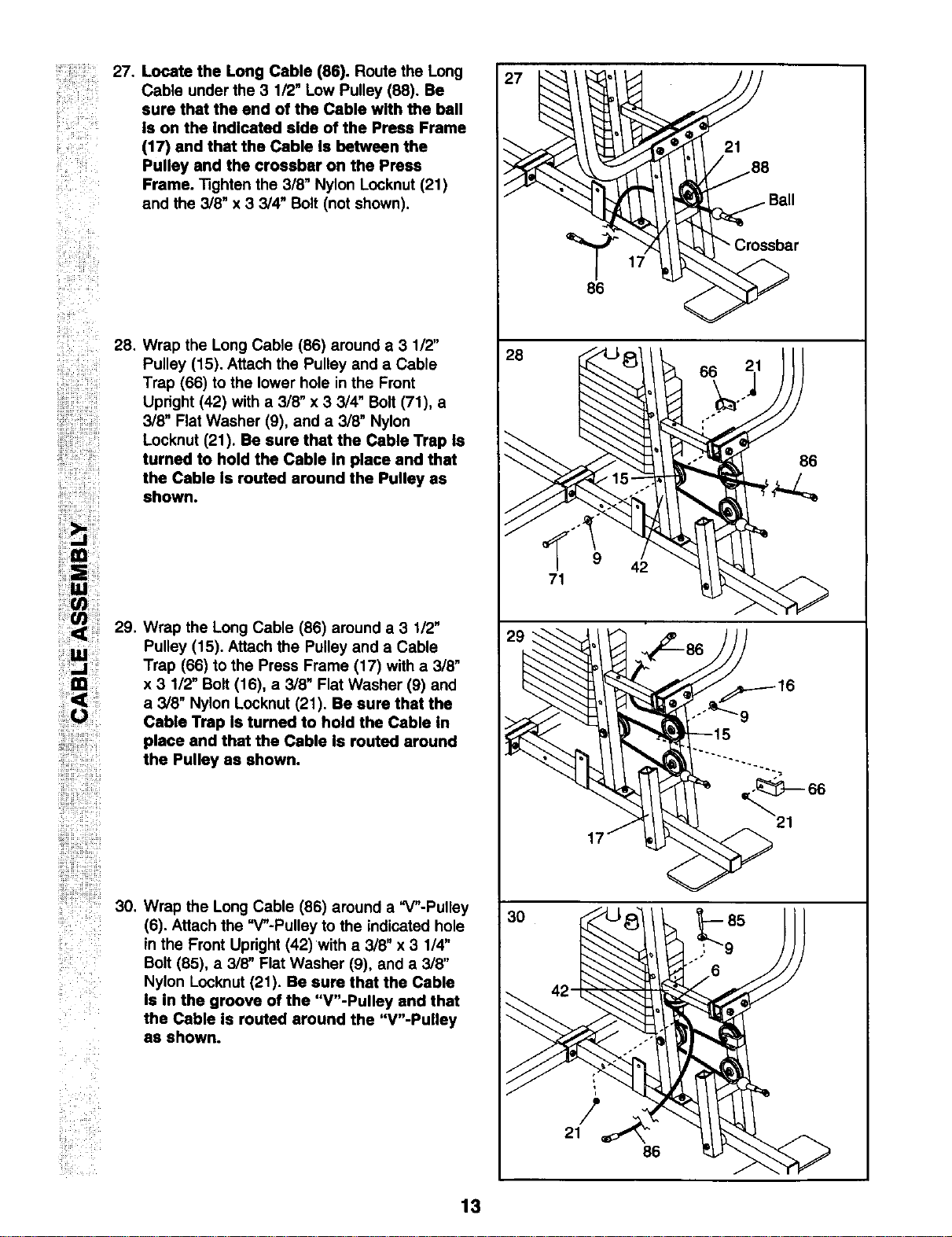
Locate the Long Cable (86). Route the Long
Cable under the 3 1/2" Low Pulley (88). Be
sure that the end of the Cable with the ball
Is on the Indicated side of the Press Frame
(17) and that the Cable Is between the
Pulley and the crossbar on the Press
Frame. Tighten the 3/8" Nylon Locknut (21)
and the 3/8" x 3 3/4" Bolt (not shown),
Wrap the Long Cable (86) around a 3 1/2"
Pulley (15). Attach the Pulley and a Cable
Trap (66) to the lower hole in the Front
Upright (42) with a 3/8" x 3 3/4" Bolt (71), a
3/8" Flat Washer (9), and a 3/8" Nylon
Locknut (21). Be sure that the Cable Trap Is
turned to hold the Cable In place and that
the Cable Is routed around the Pulley as
shown.
29. Wrap the Long Cable (86) around a 3 1/2"
Pulley (15). Attach the Pulley and a Cable
Trap (66) to the Press Frame (17) with a 3/8"
x 3 1/2" Bolt (16), a 3/8" Flat Washer (9) and
a 3/8" Nylon Locknut (21). Be sure that the
Cable Trap Is turned to hold the Cable In
place and that the Cable Is routed around
the Pulley as shown.
Wrap the Long Cable (86) around a "V"-Pulley
(6). Attach the "V"-Pulley to the indicated hole
in the Front Upright (42)with a 3/8" x 3 1/4"
Bolt (85), a 3/8" Flat Washer (9), and a 3/8"
Nylon Locknut (21). Be sure that the Cable
Is in the groove of the "V"-Pulley and that
the Cable Is routed around the "V"-Pultey
as shown.
27
28
86
71
42
/
21
42
86
21
86
13
_i!il ¸¸
_ ¸%1¸¸¸¸¸i
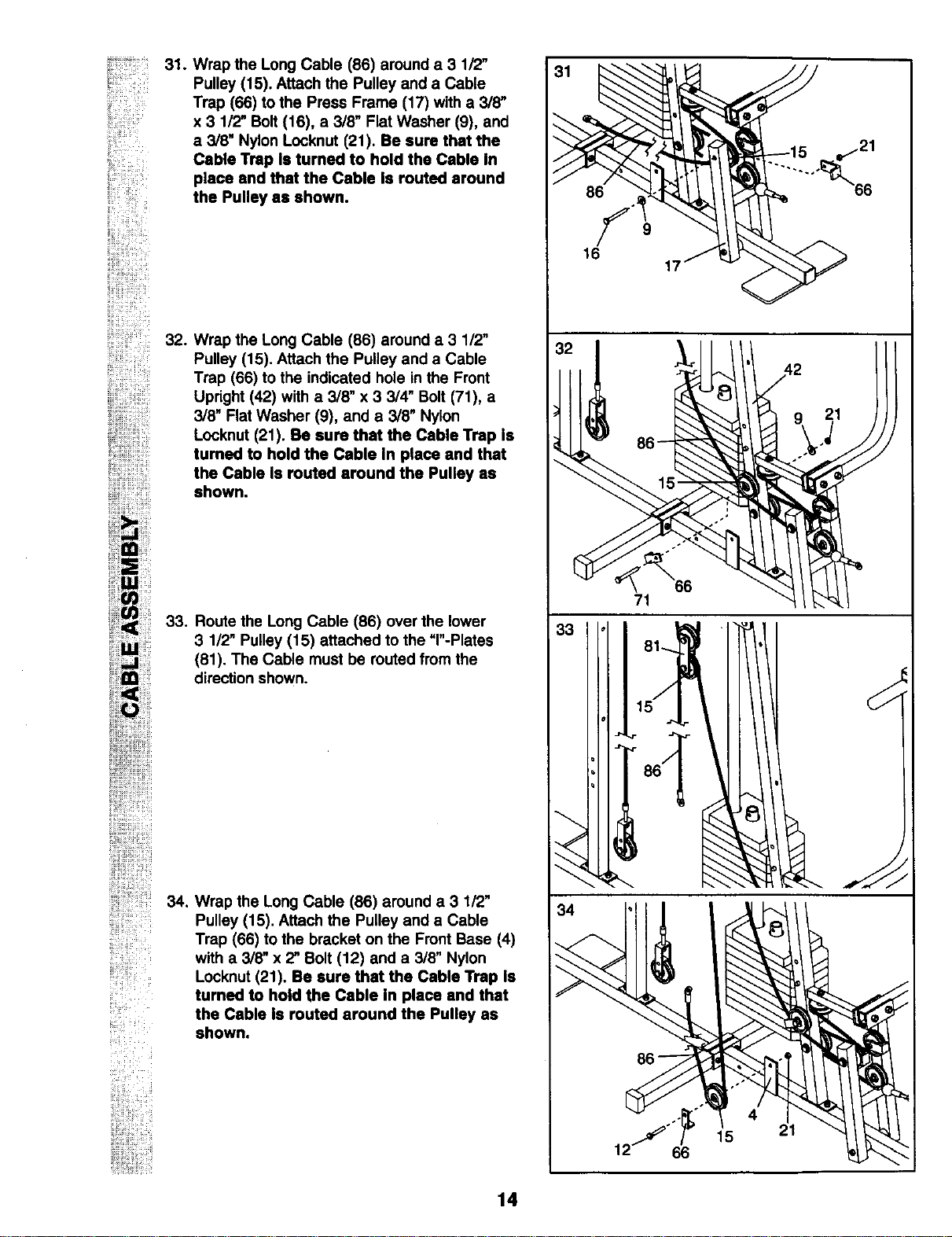
31.
Wrap the Long Cable (86) around a 3 1/2"
Pulley (15). Attach the Pulley and a Cable
Trap (66) to the Press Frame (17) with a 3/8"
x 3 1/2" Bolt (16), a 3/8" Flat Washer (9), and
a 3/8" Nylon Locknut (21). Be sure that the
Cable Trap Is turned to hold the Cable In
place end that the Cable Is routed around
the Pulley as shown.
! iiii!i!_! _i¸
32. Wrap the Long Cable (86) around a 3 1/2"
Pulley (15). Attach the Pulley and a Cable
Trap (66) to the indicated hole in the Front
Upright (42) with a 3/8" x 3 3/4" Bolt (71), a
3/8" Flat Washer (9), and a 3/8" Nylon
Locknut (21). Be sure that the Cable Trap is
turned to hold the Cable In place and that
the Cable Is routed around the Pulley as
shown.
33. Route the Long Cable (86) over the lower
3 1/2" Pulley (15) attached to the =r-Plates
(81). The Cable must be routed from the
direction shown.
_i_ii!ili!!!iiiiiiiii!i
34.
_i__i_
Wrap the Long Cable (86) around a 3 1/2"
Pulley (15). Attach the Pulley and a Cable
Trap (66) to the bracket on the Front Base (4)
with a 3/8" x 2" Bolt (12) and a 3/8" Nylon
Locknut (21). Be sure that the Cable Trap Is
turned to hold the Cable In place and that
the Cable Is routed around the Pulley as
shown.
86
9
17
_ _21
........ °_66
21
33
34
71
4
15 21
12" 66
14
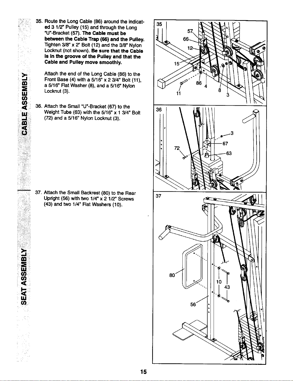
ii i_ii_i_i_iiii__
Route the Long Cable (86) around the indicat-
ed 3 1/2" Pulley (15) and through the Long
"U"-Bracket (57). The Cable must be
between the Cable Trap (66) and the Pulley.
"Rghten3/8" x 2" Bolt (12) and the 3/B" Nylon
Locknut (not shown). Be sure that the Cable
Is In the groove of the Pulley and that the
Cable and Pulley move smoothly.
Attach the end of the Long Cable (86) to the
Front Base (4) with a 5/16" x 2 3/4" Bolt (11),
a 5/16" Flat Washer (8), and a 5/16" Nylon
Locknut (3).
36. Attach the Small =U"-Bracket (67) to the
Weight Tube (63) with the 5/16" x 1 3/4" Bolt
(72) and a 5/16" Nylon Locknut (3).
37. Attach the Small Backrest (80) to the Rear
Upright (56) with two 1/4" x 2 1/2" Screws
(43) and two 1/4" Flat Washers (10).
37
11
8
15
i_ i !iiii!i!¸¸¸
_i_i__ __i_i_i_iiii_
iiii!ili_ii_i!iiii_iiiii!ii
!iiiiiii_%iiiii!i!_!_
!iil
iii_i_ii_'!iill_ i!
ii!i!iiiiiii!iiiiiiiiiiii!i
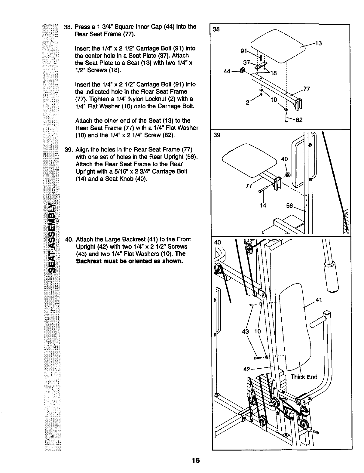
Press a 1 3/4" Square Inner Cap (44) into the
Rear Seat Frame (77).
Insert the 1/4" x 2 112"Carriage Bolt (91) into
the center hole in a Seat Plate (37). Attach
the Seat Plate to a Seat (13) with two 1/4" x
1/2" Screws (18).
Insert the 1/4" x 2 1/2" Carriage Bolt (91) into
the indicated hole in the Rear Seat Frame
(77). Tighten a 1/4" Nylon Locknut (2) with a
1/4" Flat Washer (10) onto the Carriage Bolt.
Attach the other end of the Seat (13) to the
Rear Seat Frame (77) with a 1/4" Flat Washer
(10) and the 1/4" x 2 1/4" Screw (82).
Align the holes in the Rear Seat Frame (77)
with one set of holes in the Rear Updght (56).
Attach the Rear Seat Frame to the Rear
Upright with a 5/16" x 2 3/4" Carriage Bolt
(14) and a Seat Knob (40).
40. Attach the Large Backrest (41) to the Front
Upright (42) with two 1/4" x 2 1/2" Screws
(43) and two 1/4" Flat Washers (10). The
Backrest must be oriented as shown.
38
39
77
1_4 56_
16
i_i__i_!i_
_i_!ii_ii_ ii
_ ill....
_i!!!ii!!_i_!_!i !i_
iiiii!ii!!i iiil'!
ii_ijJ
¸¸!!it,/)
i!ii!i!i i'!i! 43
i!i i ¸
i_ili
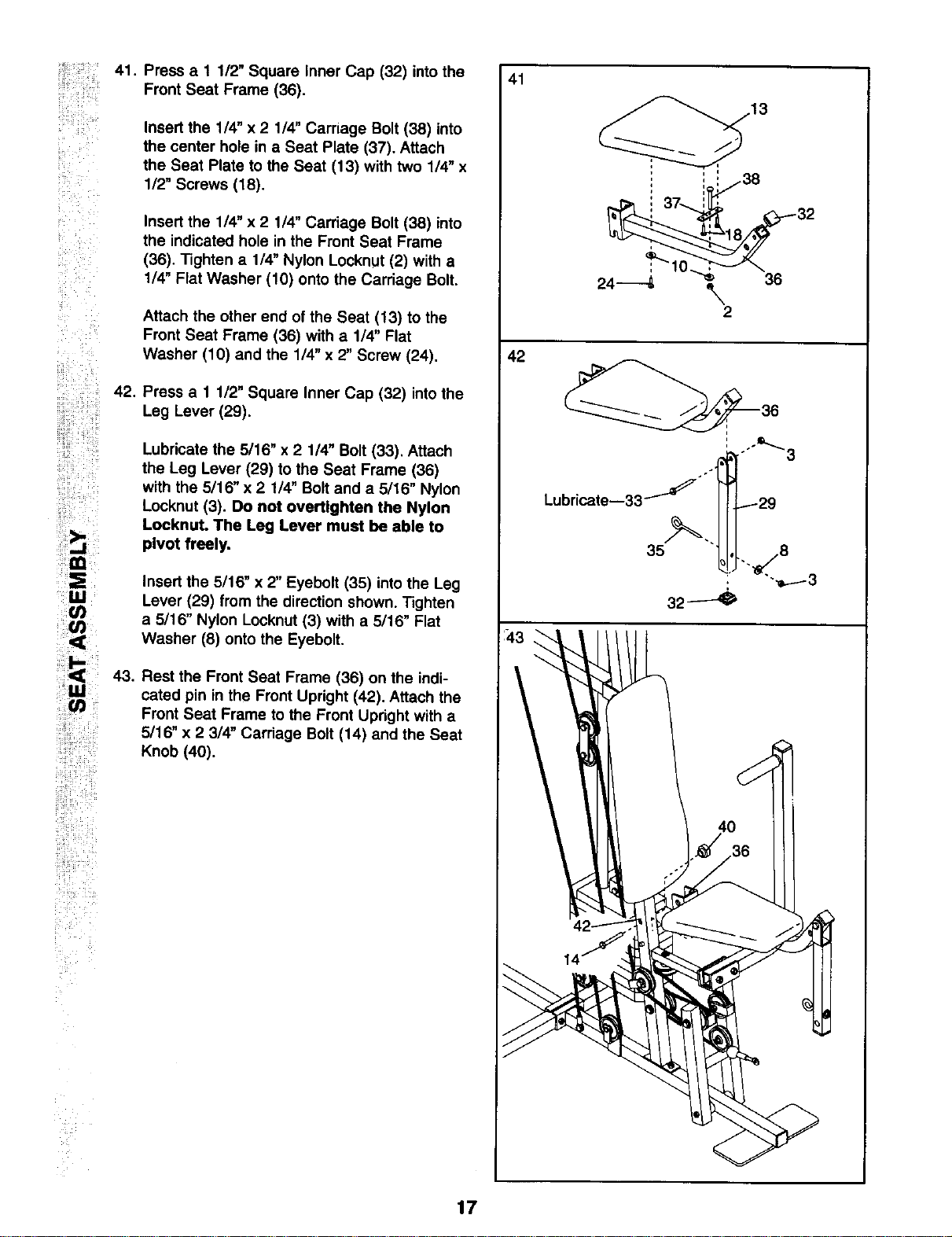
41. Press a 1 1/2" Square Inner Cap (32) into the
Front Seat Frame (36).
Insert the 1/4" x 2 1/4" Carriage Bolt (38) into
the center hole in a Seat Plate (37). Attach
the Seat Plate to the Seat (13) with two 1/4" x
112"Screws (18).
Insert the 1/4" x 2 1/4" Carriage Bolt (38) into
the indicated hole in the Front Seat Frame
(36). Tighten a 1/4" Nylon Locknut (2) with a
1/4" Flat Washer (10) onto the Carriage Bolt.
Attach the other end of the Seat (13) to the
Front Seat Frame (36) with a 1/4" Flat
Washer (10) and the 1/4" x 2" Screw (24).
Press a 1 1/2" Square Inner Cap (32) intothe
Leg Lever (29).
Lubricate the 5/16" x 2 1/4" Bolt (33). Attach
the Leg Lever (29) to the Seat Frame (36)
with the 5/16" x 2 114"Bolt and a 5/16" Nylon
Locknut (3). Do not overtlghten the Nylon
Loeknut. The Leg Lever must be able to
pivot freely.
Insert the 5/16" x 2" Eyebolt (35) into the Leg
Lever (29) from the direction shown. Tighten
a 5/16" Nylon Locknut (3) with a 5/16" Flat
Washer (8) onto the Eyebolt.
Rest the Front Seat Frame (36) on the indi-
cated pin in the Front Upright (42). Attach the
Front Seat Frame to the Front Upright with a
5/16" x 2 3/4" Carriage Bolt (14) and the Seat
Knob (40).
41
42
35
32----_
17
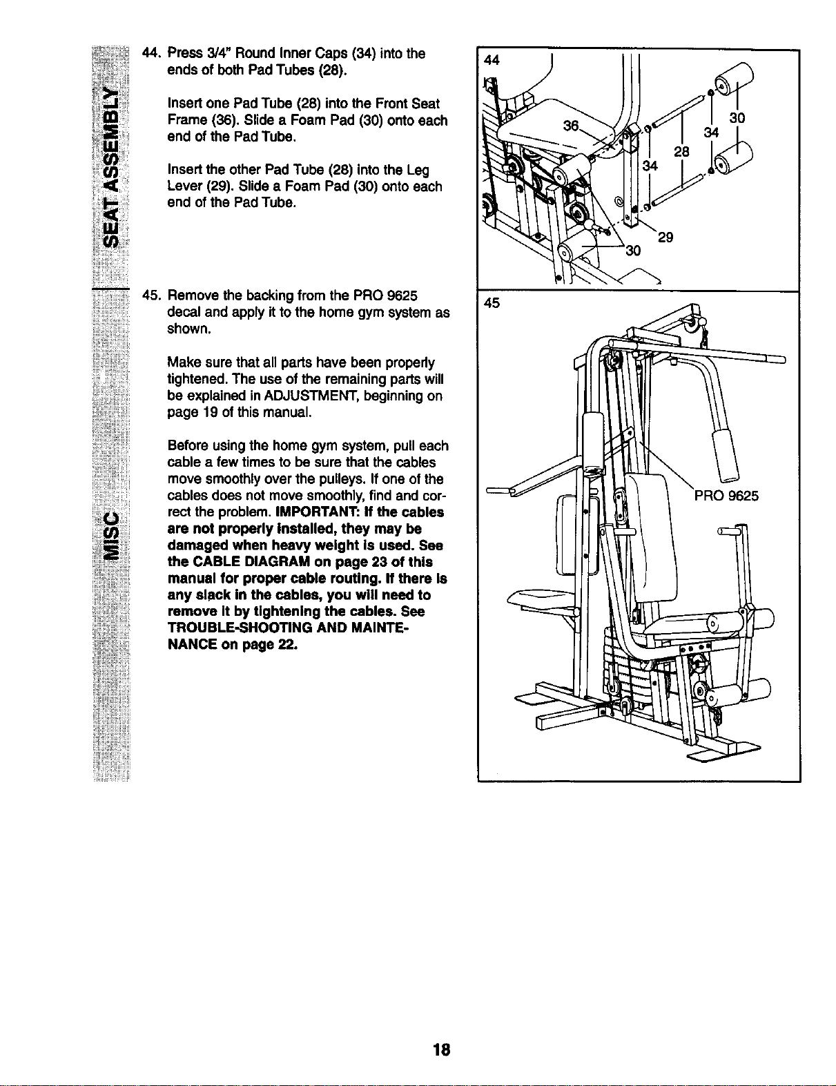
44. Press 3/4" Round Inner Caps (34) into the
ends of both Pad Tubes (28).
Insert one Pad Tube (28) into the Front Seat
Frame (36). Slide a Foam Pad (30) onto each
end of the Pad Tube.
Insert the other Pad Tube (28) into the Leg
Lever (29). Slide a Foam Pad (30) onto each
end of the Pad Tube.
45,
ii_i{_ii;ii{iiiiii{ii_
;iiiiii'_iiii_i;;Jl
ii!;i;i_!_,,i_i
!iiiiii!iii;i;;i;
! iZ_i
ii_i_ii_ii_ii_i_I_i_i
Remove the backing from the PRO 9625
decal and apply it to the home gym system as
shown.
Make sure that all parts have been propedy
tightened. The use of the remaining parts will
be explained in ADJUSTMENT, beginning on
page 19 of this manual.
Before using the home gym system, pull each
cable a few times to be sure that the cables
move smoothly over the pulleys. If one of the
cables does not move smoothly, find and cor-
rect the problem. IMPORTANT: If the cables
are not properly Installed, they may be
damaged when heavy weight Is used. See
the CABLE DIAGRAM on page 23 of this
manual for proper cable routing. If there Is
any slack in the cables, you will need to
remove It by tlghtanlng the cables. See
TROUBLE-SHOOTING AND MAINTE-
NANCE on page 22.
44
45
30
30
PRO 9625
18
ADJUSTMENT
The instructions below describe how each part of the home gym system can be adjusted. Refer to the exercise
poster accompanying this manual to see how the home gym system should be set up for each exercise.
IMPORTANT: When attaching the lat bar or nylon strap, make sure that the attachments are In the cor-
rect starting position for the exercise to be performed. If there Is any slack In the cables or chain as an
exercise Is performed, the effectiveness of the exercise will be reduced.
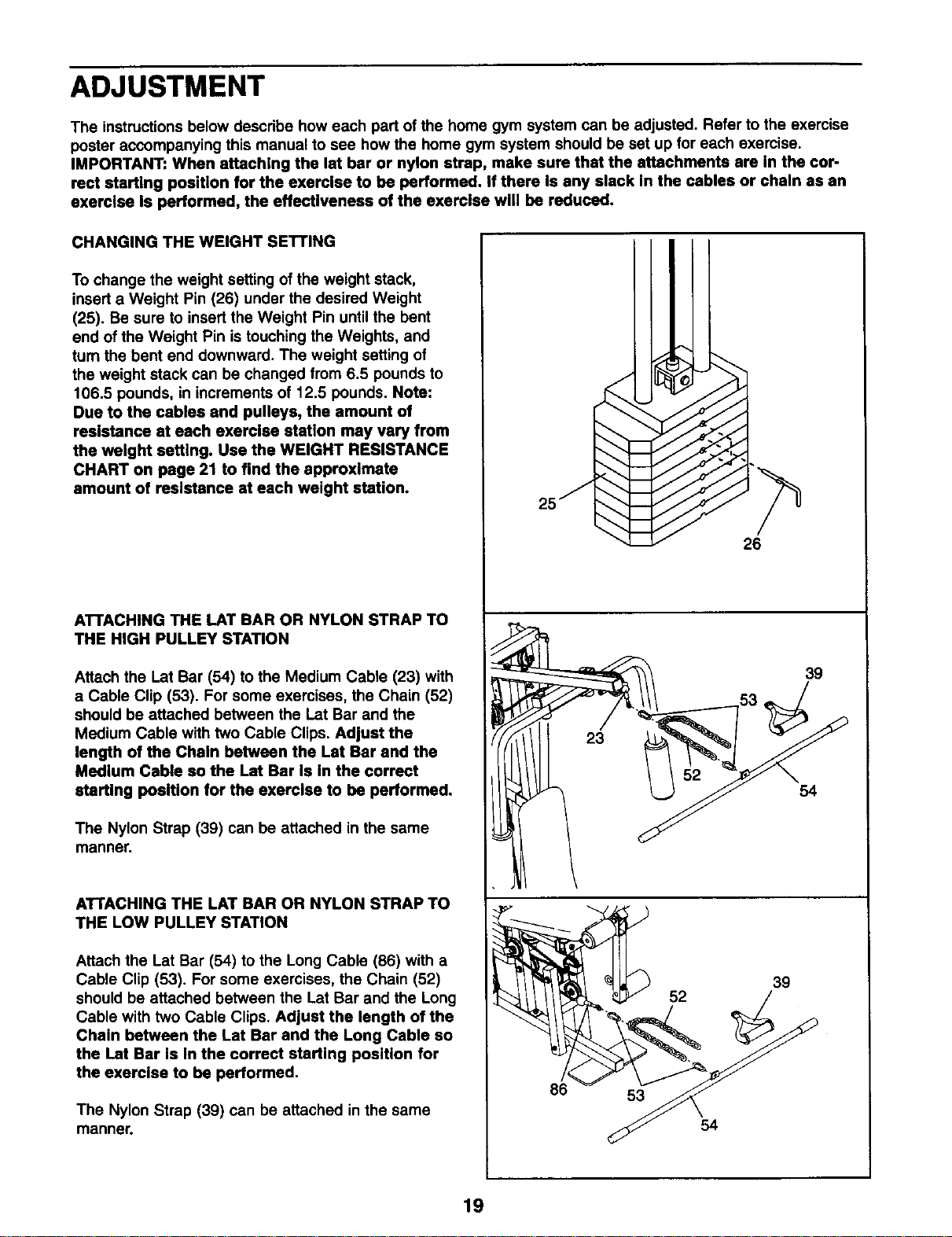
CHANGING THE WEIGHT SETrlNG
To change the weight setting of the weight stack,
insert a Weight Pin (26) under the desired Weight
(25). Be sure to insert the Weight Pin until the bent
end of the Weight Pin is touching the Weights, and
turn the bent end downward. The weight setting of
the weight stack can be changed from 6.5 pounds to
106.5 pounds, in increments of 12.5 pounds. Note:
Due to the cables and pulleys, the amount of
resistance at each exercise station may vary from
the weight setting. Use the WEIGHT RESISTANCE
CHART on page 21 to find the approximate
amount of resistance at each weight station.
ATTACHING THE LAT BAR OR NYLON STRAP TO
THE HIGH PULLEY STATION
Attach the I_atBar (54) to the Medium Cable (23) with
a Cable Clip (53). For some exercises, the Chain (52)
should be attached between the Let Bar and the
Medium Cable with two Cable Clips. Adjust the
length of the Chain between the Let Bar and the
Medium Cable so the Let Bar Is In the correct
starting position for the exercise to be performed.
The Nylon Strap (39) can be attached in the same
manner.
ATTACHING THE LAT BAR OR NYLON STRAP TO
THE LOW PULLEY STATION
Attach the Lat Bar (54) to the Long Cable (86) with a
Cable Clip (53). For some exercises, the Chain (52)
should be attached between the Lat Bar and the Long
Cable with two Cable Clips. Adjust the length of the
Chain between the Let Bar and the Long Cable so
the I.at Bar Is In the correct starting position for
the exercise to be performed.
The Nylon Strap (39) can be attached in the same
manner.
25j
86
J
"_" 26
39
53
23
54
39
52
53
54
19
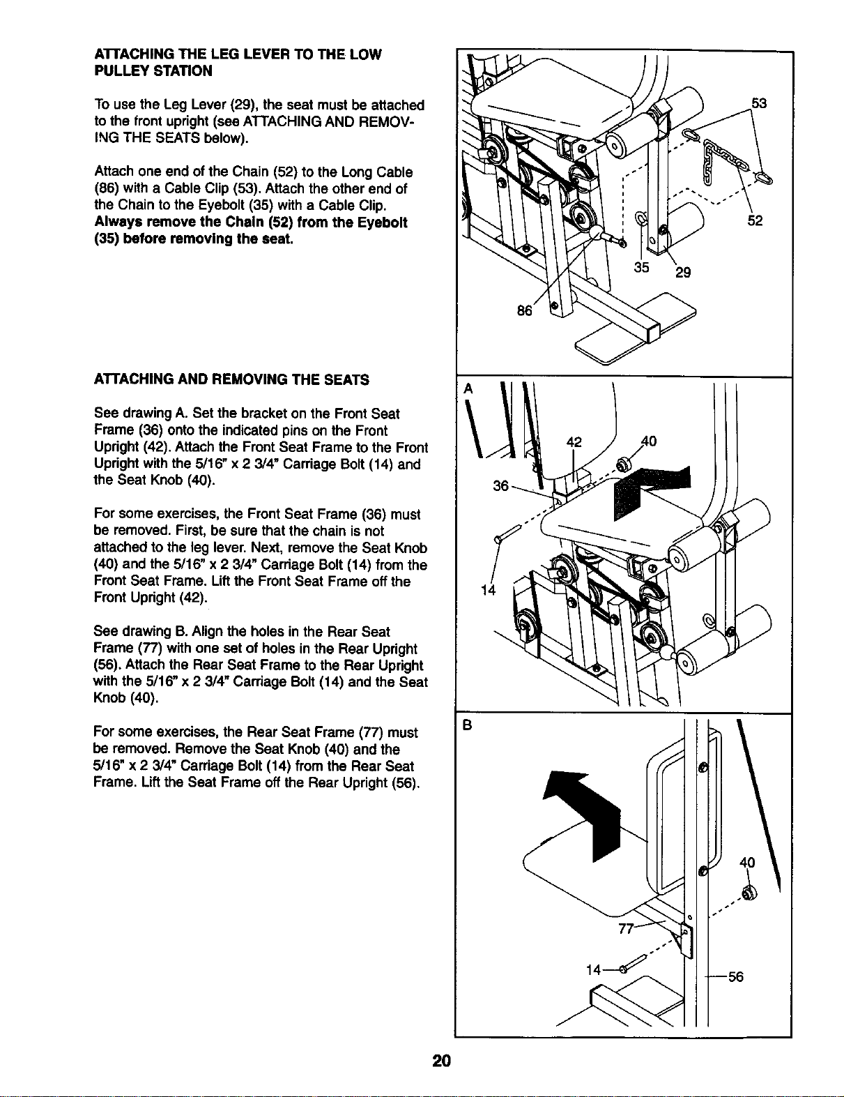
ATrACHING THE LEG LEVER TO THE LOW
PULLEY STATION
To use the Leg Lever (29), the seat must be attached
to the front upright (see ATTACHING AND REMOV-
ING THE SEATS below).
Attach one end of the Chain (52) to the Long Cable
(86) with a Cable Clip (53). Attach the other end of
the Chain to the Eyebolt (35) with a Cable Clip.
Always remove the Chain (52) from the Eyebolt
(35) before removing the seat.
ATTACHING AND REMOVING THE SEATS
See drawing A. Set the bracket on the Front Seat
Frame (36) onto the indicated pins on the Front
Updght (42). Attach the Front Seat Frame to the Front
Updght with the 5/16" x 2 3/4" Carriage Bolt (14) and
the Seat Knob (40).
For some exercises, the Front Seat Frame (36) must
be removed. First, be sure that the chain is not
attached to the leg lever. Next, remove the Seat Knob
(40) and the 5/16" x 2 314"Carriage Bolt (14) from the
Front Seat Frame. Lift the Front Seat Frame off the
Front Updght (42).
See drawing B. Align the holes in the Rear Seat
Frame (77) with one set of holes in the Rear Updght
(56). Attach the Rear Seat Frame to the Rear Upright
with the 5/16" x 2 3/4" Carriage Bolt (14) and the Seat
Knob (40).
For some exercises, the Rear Seat Frame (77) must
be removed. Remove the Seat Knob (40) and the
5/16" x 2 3/4" Cardage Bolt (14) from the Rear Seat
Frame. Lift the Seat Frame off the Rear Upright (56).
14
B
42
29
53
52
2O
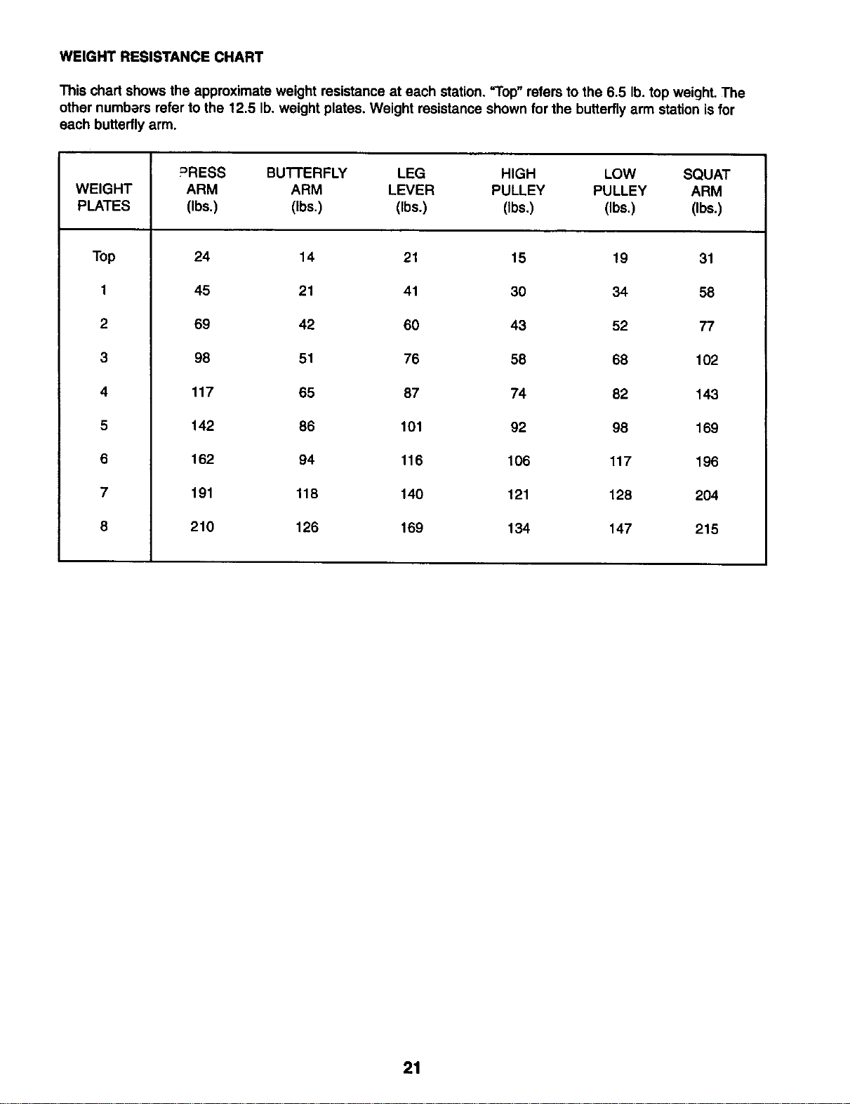
WEIGHT RESISTANCE CHART
This chart shows the approximate weight resistance at each station. "Top" refers to the 6.5 lb. top weight. The
other numbars refer to the 12.5 lb. weight plates. Weight resistance shown for the butterfly arm station is for
each butterfly arm.
WEIGHT
PLATES
Top
1
2
3
4
5
6
7
8
PRESS BUTI'ERFLY LEG HIGH LOW SQUAT
ARM ARM LEVER PULLEY PULLEY ARM
(Ibs.) (Ibs.) (Ibs.) (Ibs.) (Ibs.) (Ibs.)
24 14 21 15 19 31
45 21 41 30 34 58
69 42 60 43 52 77
98 51 76 58 68 102
117 65 87 74 82 143
142 86 101 92 98 169
162 94 116 106 117 196
191 118 140 121 128 204
210 126 169 134 147 215
21
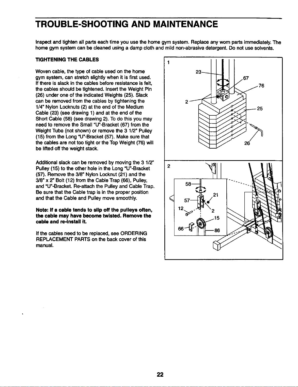
TROUBLE-SHOOTING AND MAINTENANCE
inspect and tighten all parts each time you use the home gym system. Replace any worn parts immediately. The
home gym system can be cleaned using a damp cloth and mild non-abrasive detergent. Do not use solvents.
TIGHTENING THE CABLES
Woven cable, the type of cable used on the home
gym system, can stretch slightly when it is first used.
If there is slack in the cables before resistance is felt,
the cables should be tightened. Insert the Weight Pin
(26) under one of the indicated Weights (25). Slack
can be removed from the cables by tightening the
1/4" Nylon Locknuts (2) at the end of the Medium
Cable (23) (see drawing 1) and at the end of the
Short Cable (58) (see drawing 2). To do this you may
need to remove the Small "U"-Bracket (67) from the
Weight Tube (not shown) or remove the 3 1/2" Pulley
(15) from the Long "U"-Bracket (57). Make sure that
the cables are not too tight or the Top Weight (76) will
be liftedoff the weight stack.
Additional slack can be removed by moving the 3 112"
Pulley (15) to the other hole in the Long "U"-Bracket
(57). Remove the 3/8" Nylon Locknut (21) and the
3/8" x 2" Bolt (12) from the Cable Trap (66), Pulley,
and "U"-Bracket. Re-attach the Pulley and Cable Trap.
Be sure that the Cable trap is in the proper position
and that the Cable and Pulley move smoothly.
Note: If a cable tends to slip off the pulleys often,
the cable may have become twisted. Remove the
cable and re-install It.
if the cables need to be replaced, see ORDERING
REPLACEMENT PARTS on the back cover of this
manual.
23 1 67
2_ 76
22
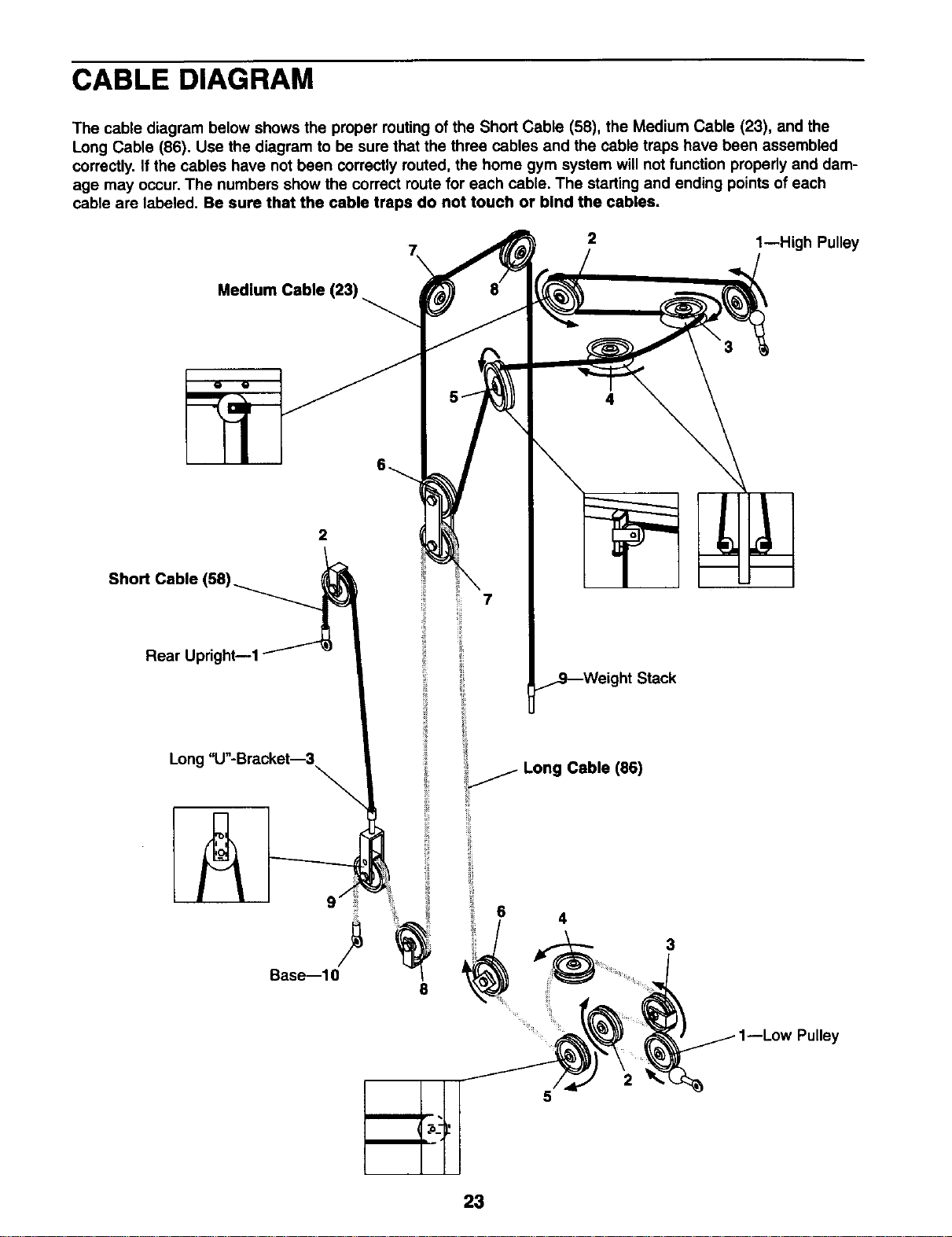
CABLE DIAGRAM
The cable diagram below shows the proper routing of the Short Cable (58), the Medium Cable (23), and the
Long Cable (86). Use the diagram to be sure that the three cables and the cable traps have been assembled
correctly. If the cables have not been correctly routed, the home gym system will not function propedy and dam-
age may occur. The numbers show the correct route for each cable. The starting and ending points of each
cable are labeled. Be sure that the cable traps do not touch or bind the cables.
Medium Cable (23)
2
Short Cable q
Rear Upright--1
7
7
2
..jg---Weight Stack
1--High Pulley
Long "U"-Bracket--8
\
i_ Long Cable (86)
Base--10
6
3
Pulley
5
23
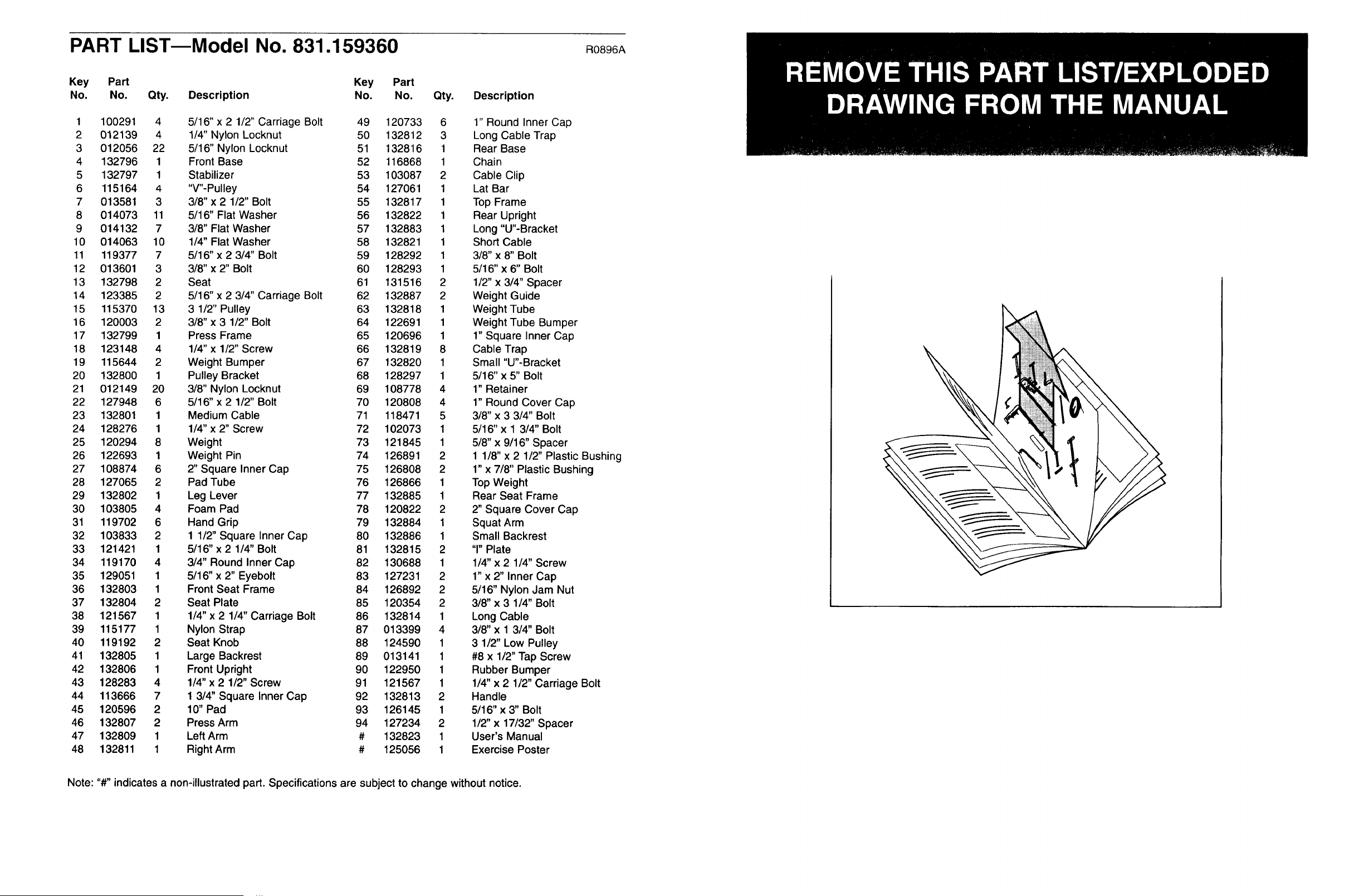
PART LISTmModel No. 831.159360 Ros96A
Key Part Key Part
No. No. Qty. Description No. No. Qty.
1 100291 4 5/16" x 2 1/2" Carriage Bolt 49 120733 6
2 012139 4 1/4" Nylon Locknut 50 132812 3
3 012056 22 5/16" Nylon Locknut 51 132816 1
4 132796 1 Front Base 52 116868 1
5 132797 1 Stabilizer 53 103087 2
6 115164 4 "V"-Pulley 54 127061 1
7 013581 3 3/8" x 2 1/2" Bolt 55 132817 1
8 014073 11 5/16" Flat Washer 56 132822 1
9 014132 7 3/8" Flat Washer 57 132883 1
10 014063 10 1/4" Flat Washer 58 132821 1
11 119377 7 5/16" x 2 3/4" Bolt 59 128292 1
12 013601 3 3/8" x 2" Bolt 60 128293 1
13 132798 2 Seat 61 131516 2
14 123385 2 5/16" x 2 3/4" Carriage Bolt 62 132887 2
15 115370 13 3 1/2" Pulley 63 132818 1
16 120003 2 3/8" x 3 1/2" Bolt 64 122691 1
17 132799 1 Press Frame 65 120696 1
18 123148 4 1/4" x 1/2" Screw 66 132819 8
19 115644 2 Weight Bumper 67 132820 1
20 132800 1 Pulley Bracket 68 128297 1
21 012149 20 3/8" Nylon Locknut 69 108778 4
22 127948 6 5/16" x 2 1/2" Bolt 70 120808 4
23 132801 1 Medium Cable 71 118471 5
24 128276 1 1/4" x 2" Screw 72 102073 1
25 120294 8 Weight 73 121845 1
26 122693 1 Weight Pin 74 126891 2
27 108874 6 2" Square Inner Cap 75 126808 2
28 127065 2 Pad Tube 76 126866 1
29 132802 1 Leg Lever 77 132885 1
30 103805 4 Foam Pad 78 120822 2
31 119702 6 Hand Grip 79 132884 1
32 103833 2 1 1/2" Square Inner Cap 80 132886 1
33 121421 1 5/16" x 2 1/4" Bolt 81 132815 2
34 119170 4 3/4" Round Inner Cap 82 130688 1
35 129051 1 5/16" x 2" Eyebolt 83 127231 2
36 132803 1 Front Seat Frame 84 126892 2
37 132804 2 Seat Plate 85 120354 2
38 121567 1 1/4" x 2 1/4" Carriage Bolt 86 132814 1
39 115177 1 Nylon Strap 87 013399 4
40 119192 2 Seat Knob 88 124590 1
41 132805 1 Large Backrest 89 013141 1
42 132806 1 Front Upright 90 122950 1
43 128283 4 1/4" x 2 1/2" Screw 91 121567 1
44 113666 7 1 3/4" Square Inner Cap 92 132813 2
45 120596 2 10" Pad 93 126145 1
46 132807 2 Press Arm 94 127234 2
47 132809 1 Left Arm # 132823 1
48 132811 1 Right Arm # 125056 1
Description
1" Round Inner Cap
Long Cable Trap
Rear Base
Chain
Cable Clip
Lat Bar
Top Frame
Rear Upright
Long "U"-Bracket
Short Cable
3/8" x 8" Bolt
5/16"x 6" Bolt
1/2" x 3/4" Spacer
Weight Guide
Weight Tube
Weight Tube Bumper
1" Square Inner Cap
Cable Trap
Small "U"-Bracket
5/16"x 5" Bolt
1" Retainer
1" Round Cover Cap
3/8" x 3 3/4" Bolt
5/16"x 1 3/4" Bolt
5/8" x 9/16" Spacer
1 1/8" x 2 1/2" Plastic Bushing
1" x 7/8" Plastic Bushing
Top Weight
Rear Seat Frame
2" Square Cover Cap
Squat Arm
Small Backrest
"r' Plate
1/4" x 2 1/4" Screw
1" x 2" Inner Cap
5/16" Nylon Jam Nut
3/8" x 3 1/4" Bolt
Long Cable
3/8" x 1 3/4" Bolt
3 1/2" Low Pulley
#8 x 1/2" Tap Screw
Rubber Bumper
1/4" x 2 1/2" Carriage Bolt
Handle
5/16" x 3" Bolt
1/2" x 17/32" Spacer
User's Manual
Exercise Poster
Note: "#" indicates a non-illustrated part. Specifications are subject to change without notice.
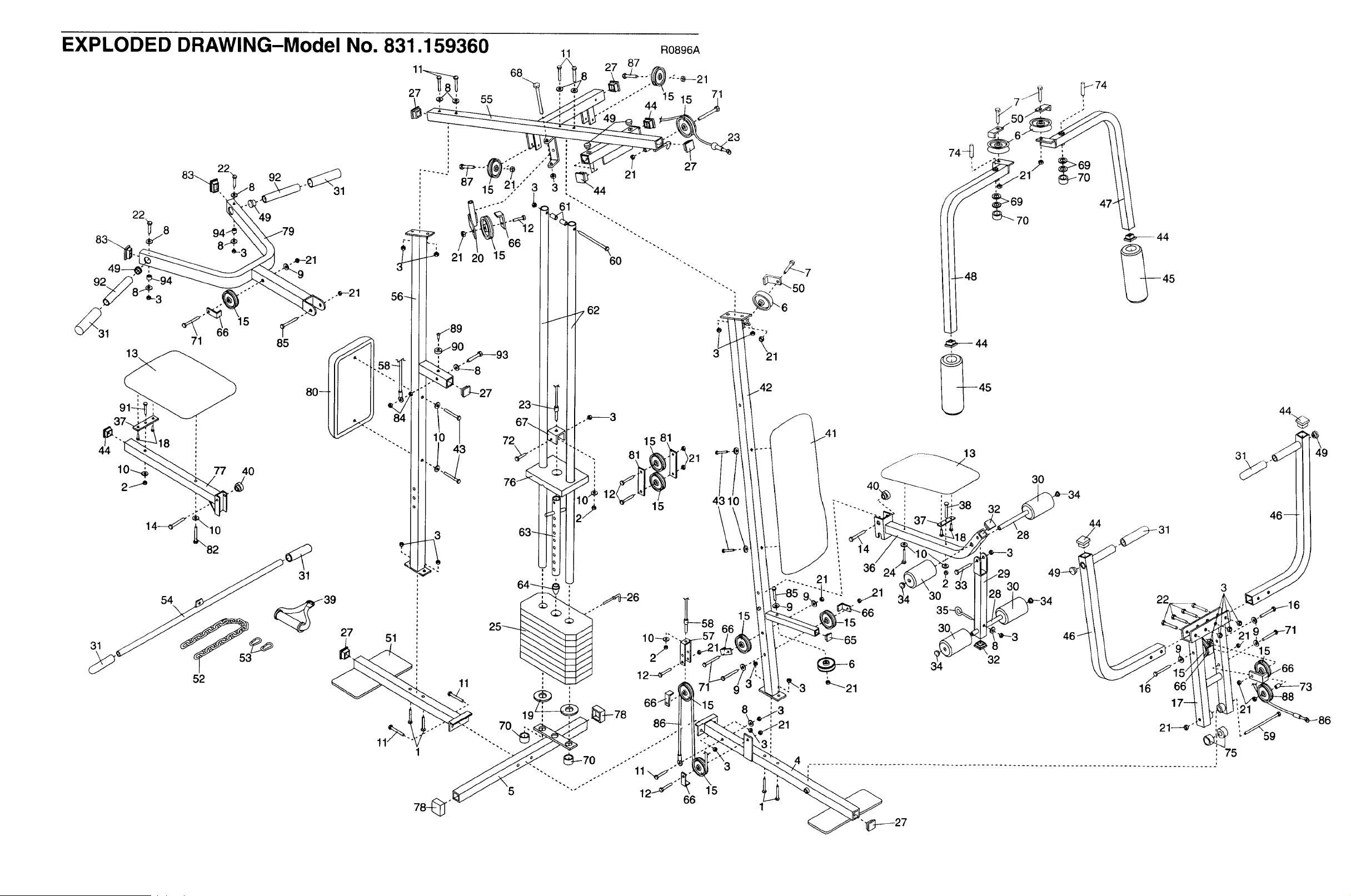
EXPLODED DRAWING-Model No. 831.1 59360
92
0-3
_31 66 5
71
13\
54
\
52
31
85
/
80- I
31
_39 27
51
61
60
62
50
' _6
a 21
42
11%
I
71
\15 8 I 3
_]--78 __21 21_--_ i 75
86_ . ' -":.-_ i • i "
..........................................................................................
"'"-'"'" 12_"_6 1"5
31
59
86
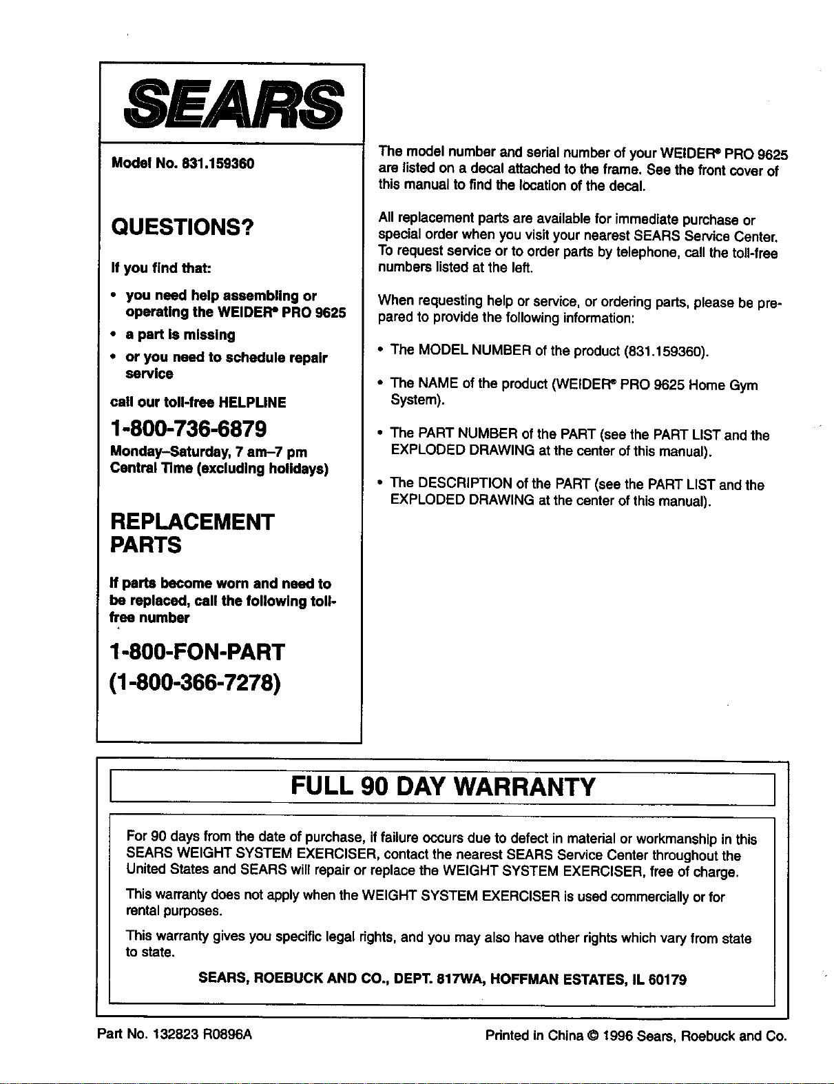
SEARS
Model No. 631.159360
QUESTIONS?
If you find that:
• you need help assembling or
operaUng the WELDER=PRO 9625
• a part Is missing
• or you need to schedule repair
service
call our toll-frae HELPLINE
1-800-736-6879
Monday-Saturday, 7 am-7 pm
Central Time (excluding holidays)
REPLACEMENT
PARTS
If parts become worn and need to
be replaced, call the following toll-
free number
1-800-FON-PART
(1-800-366-7278)
The model number and serial number of your WEIDEFP PRO 9625
are listed on a decal attached to the frame. See the front cover of
this manual to find the location of the decal.
All replacement parts are available for immediate purchase or
special order when you visit your nearest SEARS Service Center.
To request service or to order parts by telephone, call the toll-free
numbers listed at the left.
When requesting help or service, or ordering parts, please be pre-
pared to provide the following information:
• The MODEL NUMBER of the product (831.159360).
• The NAME of the product (WEIDEFP PRO 9625 Home Gym
System).
• The PART NUMBER of the PART (see the PART LIST and the
EXPLODED DRAWING at the center of this manual).
• The DESCRIPTION of the PART (see the PART LIST and the
EXPLODED DRAWING at the center of this manual).
FULL 90 DAY WARRANTY
For 90 days from the date of purchase, if failure occurs due to defect in material or workmanship in this
SEARS WEIGHT SYSTEM EXERCISER, contact the nearest SEARS Service Center throughout the
United States and SEARS will repair or replace the WEIGHT SYSTEM EXERCISER, free of charge.
This warranty does not apply when the WEIGHT SYSTEM EXERCISER is used commercially or for
rental purposes.
This warranty gives you specific legal rights,and you may also have other rights which vary from state
to state.
SEARS, ROEBUCK AND CO., DEPT. 617WA, HOFFMAN ESTATES, IL 60179
Part No. 132823 RO896A Pdnted in China © 1996 Sears, Roebuck and Co.