Loading ...
Loading ...
Loading ...
INSTALLATION OF WHEELS (Hardware E)
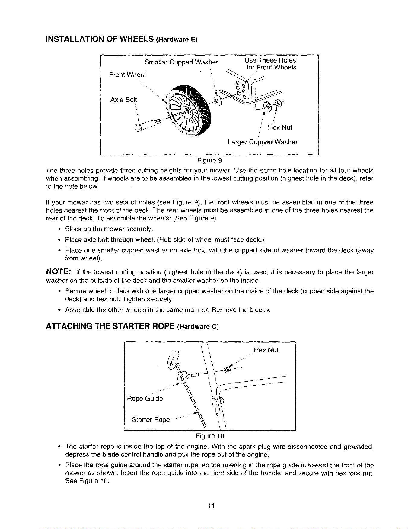
Smaller Cupped Washer Use These Holes
for Front Wheels
Front Wheel
\
\
Axle Bolt
/
/ Hex Nut
Larger Cupped Washer
Figure 9
The three holes provide three cutting heights for your mower. Use the same hole location for all four wheels
when assembling. If wheels are to be assembled in the lowest cutting position (highest hole in the deck), refer
to the note below.
If your mower has two sets of holes (see Figure 9), the front wheels must be assembled in one of the three
holes nearest the front of the deck. The rear wheels must be assembled in one of the three holes nearest the
rear of the deck. To assemble the wheels: (See Figure 9).
• Block up the mower securely.
• Place axle bolt through wheel. (Hub side of wheel must face deck.)
• Place one smaller cupped washer on axle bolt, with the cupped side of washer toward the deck (away
from wheel).
NOTE: If the lowest cutting position (highest hole in the deck) is used, it is necessary to place the larger
washer on the outside of the deck and the smaller washer on the inside.
• Secure wheel to deck with one larger cupped washer on the inside of the deck (cupped side against the
deck) and hex nut. Tighten securely.
• Assemble the other wheels in the same manner. Remove the blocks.
ATTACHING THE STARTER ROPE (Hardware C)
Hex Nut
J
Starter Rope
Figure 10
• The starter rope is inside the top of the engine. With the spark plug wire disconnected and grounded,
depress the blade control handle and pull the rope out of the engine.
• Place the rope guide around the starter rope, so the opening in the rope guide is toward the front of the
mower as shown. Insert the rope guide into the right side of the handle, and secure with hex lock nut.
See Figure 10.
11
Loading ...
Loading ...
Loading ...