Loading ...
Loading ...
Loading ...
Page 16
6. Installation
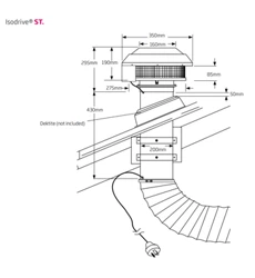
Step 3
Using a leveller, level the rangehood using
screws (A).
Once levelled, secure it rmly to the wall (C)
using the appropriate screws.
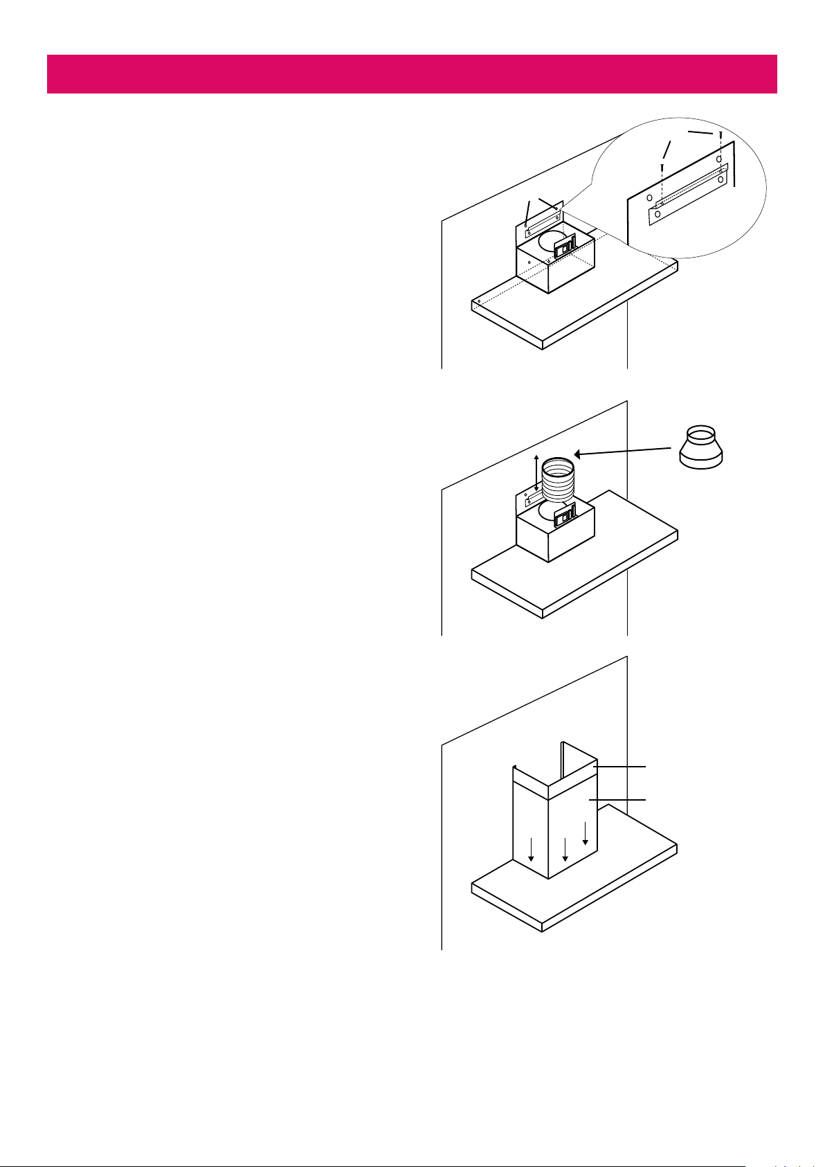
Step 4
Feed through and secure the exi ducting from
the rangehood outlet to the Isodrive motor.
• The reducer is to be placed on top of the
200mm outlet on the rangehood when using
a 650 Isodrive motor only.
Step 5
Place ue covers onto the rangehood and adjust
the height of the ue covers by sliding the outer
ue cover down.
NOTE: The outer ue cover section alone will
not cover the entirety of the control box and
PCB computer board.
A
C
Inner ue cover
Outer ue cover
Loading ...
Loading ...
Loading ...