
DLP Cinema
®
Projector Installation manual
NC800C
NC800C Important Information
E-2
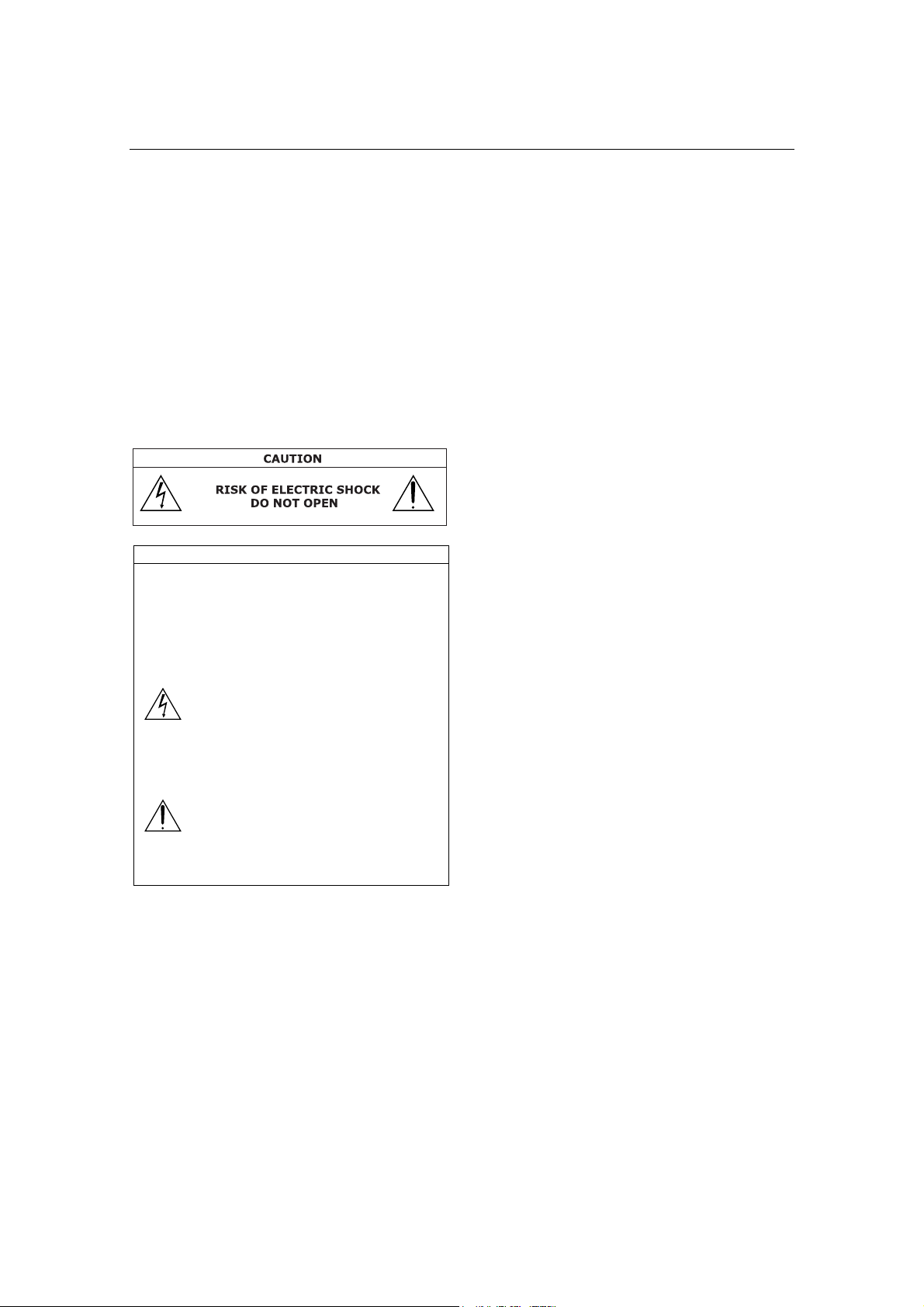
WARNING
TO PREVENT FIRE, SHOCK, OR OTHER
HAZARDS, DO NOT EXPOSE THIS UNIT TO
RAIN OR MOISTURE. ALSO DO NOT USE
THIS UNIT’S POLARIZED PLUG WITH
AN EXTENSION CORD RECEPTACLE OR
OTHER OUTLETS, UNLESS THE PRONGS CAN
BE FULLY INSERTED. REFRAIN FROM
OPENING
THE CABINET AS THERE ARE
HIGH-VOLTAGE COMPONENTS INSIDE. REFER
SERVICING TO QUALIFIED SERVICE
PERSONNEL.
CAUTION
TO REDUCE THE RISK OF ELECTRIC SHOCK, DO
NOT OPEN COVER. NO USER-SERVICEABLE PARTS
INSIDE. REFER SERVICING TO QUALIFIED SERVICE
PERSONNEL.
This symbol warns the user that uninsulated
voltage within the unit may have sufficient
magnitude to cause electric shock. Therefore,
it
is dangerous to make any kind of contact
with any part inside of this unit.
This symbol alerts the user that important
literature concerning the operation
and maintenance of this unit has been
included. Therefore, it should be read
carefully in order to avoid any problems.
DOC compliance Notice
This Class A digital apparatus meets
all requirements of the Canadian Interference-
Causing Equipment Regulations.
Precautions: Please read this manual
carefully before using your NC800C
and keep the manual handy for future
reference.
WARNING
This is a Class A product. In a domestic
environment this product may cause
radio interference in which case the
user may be required to take adequate
measures.
CAUTION
• In order to reduce any interference
with radio and television reception use a
signal cable with ferrite core attached.
Use of signal cables without a ferrite
core attached may cause interference
with radio and television reception.
• This equipment has been tested and
found to comply with the limits for a
Class A digital device, pursuant to Part
15 of the FCC Rules. These limits are
designed to provide reasonable protection
against harmful interference when the
equipment is operated in a commercial
environment.
This equipment generates, uses, and
can radiate radio frequency energy and,
if not installed and used in accordance
with the installation manual, may cause
harmful interference to radio communications.
Operation of this equipment in a residential
area is likely to cause harmful interference
in
which case the user will be required
to correct the interference at his own
expense.
Important Safeguards
These safety instructions are to ensure the
long life of your projector and to prevent
fire and shock. Please read them carefully
and heed all warnings.
Installation
1. Continual place the projector on a
flat, level surface in a dry area away
from dust and moisture. Tilting the
front of the projector up or down
could reduce lamp life. Do not put
the projector on its side
when the
lamp is on. Doing so may cause
damage to the projector.

NC800C Important Information
E-3
2. Do not place the projector in direct
sunlight, near heaters or heat radiating
appliances.
3. Exposure to direct sunlight, smoke
or steam could harm internal components.
4. Handle your projector carefully.
Dropping or jarring your projector
could damage internal components.
5. To carry the projector, a minimum
of four persons are required. Do
not hold the lens part and the
anamorphic lens part with your
hand. Otherwise the projector may
tumble or drop, causing personal
injury.
6. Do not place heavy objects on top
of the projector.
7. If you wish to have the projector
installed on the ceiling:
a Do not attempt to install the
projector yourself.
b The projector must be installed
by qualified technicians in order
to
ensure proper operation and
reduce the risk of bodily injury.
c In addition, the ceiling must be
strong enough to support the
projector and the installation
must be in accordance with
any local building codes.
d Please consult your dealer for
more information.
e
Do not attempt to stack projectors
on the ceiling.
Power Supply
1. The projector is so designed that it
operates with the power supply voltage
described below.
• 1.2kW (Max. 12A) AC100-120V
50/60Hz
• 1.7kW (Max. 8.5A) AC200-240V
50/60Hz
Ensure that your power supply fits
this requirement before attempting
to use your projector.
2. Consult your dealer about installing
the power cord to the projector.
DO NOT install the power cord by
yourself.
Doing so may cause a fire
or electric shock.
3.
Handle the power cord carefully and
avoid excessive bending. Do not place
any heavy objects on the power cord. A
damaged cord can cause electric shock
or fire.
4. If the projector will not be used for
an extended period of time, shut down
AC power.
5.
Placing the power cord and the signal
cable closely to each other can cause
beat noise. Beat noise is corruption of
the picture often seen as a rolling
band moving through the image.
Keep the two separated, to ensure
beat noise is not generated.
6. Do not touch the projector during a
thunder storm. Doing so can cause
electrical shock or fire.
Cleaning
1.
Unplug the projector before cleaning.
2. Clean the cabinet periodically with
a damp cloth. If heavily soiled, use
a mild detergent. Never use strong
detergents or solvents such as alcohol
or thinner.
3. Use a blower or lens paper to clean
the lens, and be careful not to scratch
or mar the lens.
Fire and Shock Precautions
1.
Ensure that there is sufficient ventilation
and that vents are unobstructed to
prevent potentially dangerous concentrations
of ozone and the build-up of heat
inside your projector. Allow at least
8 inches (20cm) of space between
your projector and a wall. Connect
the projector exhaust outlet with the
exhaust equipment having a capacity of
16m
3
/min or more.
2.
Prevent foreign objects such as paper
clips and bits of paper from falling
into your projector. Do not attempt
to retrieve any objects that might fall
into your projector. Do not insert any
metal objects such as a wire or
screwdriver into your projector. If
something should fall into your
projector, disconnect
it immediately
and have the object
removed by a

NC800C Important Information
E-4
qualified service person.
3.
Do not place any liquids on top of your
projector. Refer servicing to qualified
service personnel if liquid has been
spilled.
4. Keep any items such as magnifying
glass out of the light path of the
projector. The light being projected
from the lens is extensive, therefore
any kind of abnormal objects that
can redirect light coming out of the
lens, can cause unpredictable outcome
such as fire or injury to the eyes.
5.
Do not cover the lens with the supplied
lens cap or equivalent while the projector is
on. Doing so can lead to melting of the
cap and possibly burning your hands
due to the heat emitted from the
light output.
6.
When using a LAN cable:
For safety, do not connect to the
connector
for peripheral device wiring
that might have excessive Voltage.
CAUTION:
High Pressure Lamp May
Explode if Improperly Handled.
Refer Servicing to Qualified
Service Personnel.
Lamp Caution: Please
read before operation
Due to the lamp being sealed in a
pressurized environment, there is a
small risk of explosion, if not operated
correctly.There is minimal risk involved,
if
the unit is in proper working order, but
if
damaged or operated beyond the
recommended hours, the risk of explosion
increases. Please note that there is a
warning system built in, that displays
following message when you reach a
preset operating time “Over Time Bulb”.
When you see this message please contact
your dealer for a replacement. If the
lamp does explode, smoke will be discharged
from the vents located on the back of
the unit. Do not stand in front of the
vents during the operation. This smoke is
comprised of glass in particulate form
and Xenon gas, and will not cause harm
if
kept out of your eyes. If your eyes have
been exposed to this gas, please flush
your eyes out with water immediately and
seek immediate medical attention. Do
not rub your eyes! This could cause
serious injury.
WARNING:
Do not look into the lens while the
projector is on. Serious damage to
your eyes could result.
CAUTION
Never unplug the projection head power
plug from the outlet under the following
conditions. Doing so can cause damage to
the projector:
• While projecting image
• While cooling after the projector has
been turned off. (The POWER indicator
blinks in orange while the fan is rotating,
and the LCD screen is displaying
“cooling…”. The cooling fan continues to
work for 3 minutes.)
Remote Control Precautions
• Handle the remote control carefully.
• If the remote control gets wet, wipe
it dry immediately.
• Avoid excessive heat and humidity.
• Do not heat, take apart, or throw
batteries into fire.
• If you will not be using the remote
control for a long time, remove the
batteries.
• Ensure that you have the batteries’
polarity (+/-) aligned correctly.
• Do not use new and old batteries
together, or use different types of
batteries together.
• Dispose of used batteries according
to your local regulations.

NC800C Important Information
E-5
Disposing of your used product
EU-wide legislation as implemented
in each Member State requires
that used electrical and electronic
products carrying the mark (left)
must be disposed of separately
from normal household waste.
This includes projectors and their
electrical accessories or lamps.
When you dispose of such products,
please follow the guidance of your
local authority and/or ask the
shop where you purchased the
product. After collecting the used
products, they are reused and
recycled in a proper way. This
effort will help us reduce the
wastes as well as the negative
impact to the human health and
the environment at the minimum
level. The mark on the electrical
and electronic products only applies
to the current European Union
Member States.
For questions relating to unclear
points or repairs
Contact your dealer or the following support
branches for questions relating to unclear
points, malfunctions and repairs of the
product.
In Europe
NEC Europe, Ltd. / European Technical Centre
Address: Unit G, Stafford Park 12, Telford
TF3 3BJ, U.K.
Telephone: +44 1952 237000
Fax Line: +44 1952 237006
In North America
NEC Corporation of America
Digital Cinema Division
Address: 4111 West Alameda Avenue
Suite 412 Burbank, CA 91505
Telephone: 818 557 2500
*If the above line is busy, please dial as
below;
Telephone: 866 632 6431

NC800C Table of Contents
E-6
Table of Contents
Important Information .........................................................................................E-2
Table of Contents ..................................................................................................E-6
1.
Before Setting Up Your Projector
........ E-8
1.1 Selecting Primary/Anamorphic Lenses for Your Projector ................E-8
1.2 Screen Type ......................................................................................E-9
1.3 Selecting of Anamorphic Lenses........................................................... 9
1.4 Selection of Primary Lens................................................................E-10
1.5 List of Tools Used ............................................................................E-12
2. Setting Up Your Projector....... E-13
2.1 Connecting the Power Cord .............................................................E-13
2.1.1 Be sure to secure the power plug as follows: ........................................... E-14
2.1.2 When Using an EU Type Power Cable ...................................................... E-14
2.2 Setup Required for Overhead Installation .......................................E-15
2.3 Mounting the primary lens ..............................................................E-17
2.4 Mounting the Anamorphic Lens and Its Holder................................E-20
2.5
Installation of Small Iris
(Information for Service Personnel)
...............................E-23
2.6 Affixing the security label ...............................................................E-25
3.
Connecting to the Projector
........ E-26
3.1 Connecting the image input ............................................................E-26
3.2 Connecting the various control terminal .........................................E-27
3.3
Controlling Your Projector Using a Wireless LAN Card
.............................E-28
4. Projector Adjustment ............. E-29
4.1 Setting the projector projection method .........................................E-29
4.2 Adjusting the primary lens ..............................................................E-30
4.2.1 Display the test pattern ........................................................................ E-30
4.2.2 Adjusting the screen ratio ..................................................................... E-31
4.3 Adjusting the anamorphic lens........................................................E-32
5. LCD Menu ............................... E-36
5.1 When you use the service personnel menu .....................................E-36
5.2 List of menu ....................................................................................E-37
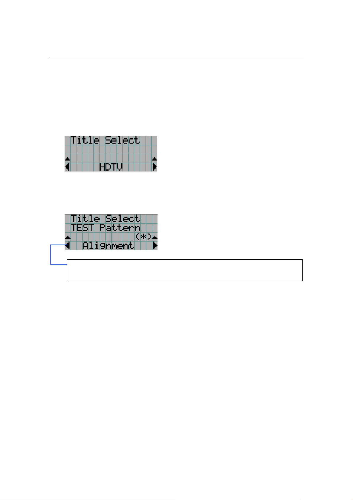
5.3 Title Select ......................................................................................E-38
5.3.1 Title select (Title Memory)..................................................................... E-38

NC800C Table of Contents
E-7
5.3.2 Test Pattern ......................................................................................... E-38
5.4 Configuration ..................................................................................E-39
5.4.1 Lamp Setup......................................................................................... E-39
5.4.2 Setup ................................................................................................. E-39
5.4.3 Installation .......................................................................................... E-41
5.4.4 Memory .............................................................................................. E-43
5.5 Title Setup.......................................................................................E-43
5.5.1 Macro Key ........................................................................................... E-43
5.6 Information.....................................................................................E-44
5.6.1 Lamp .................................................................................................. E-44
5.6.2 Macro Key ........................................................................................... E-44
5.6.3 Usage ................................................................................................. E-44
5.6.4 Error Code........................................................................................... E-45
5.6.5 Version ............................................................................................... E-45
5.6.6 IP Address........................................................................................... E-45
5.6.7 MMS Status ......................................................................................... E-46
6. Appendix ................................ E-47
6.1 List of registered titles (when shipped from the factory) ................E-47
6.2 Index ..............................................................................................E-48
E-8
1.
Before Setting Up Your
Projector
1.1 Selecting Primary/Anamorphic Lenses for Your
Projector
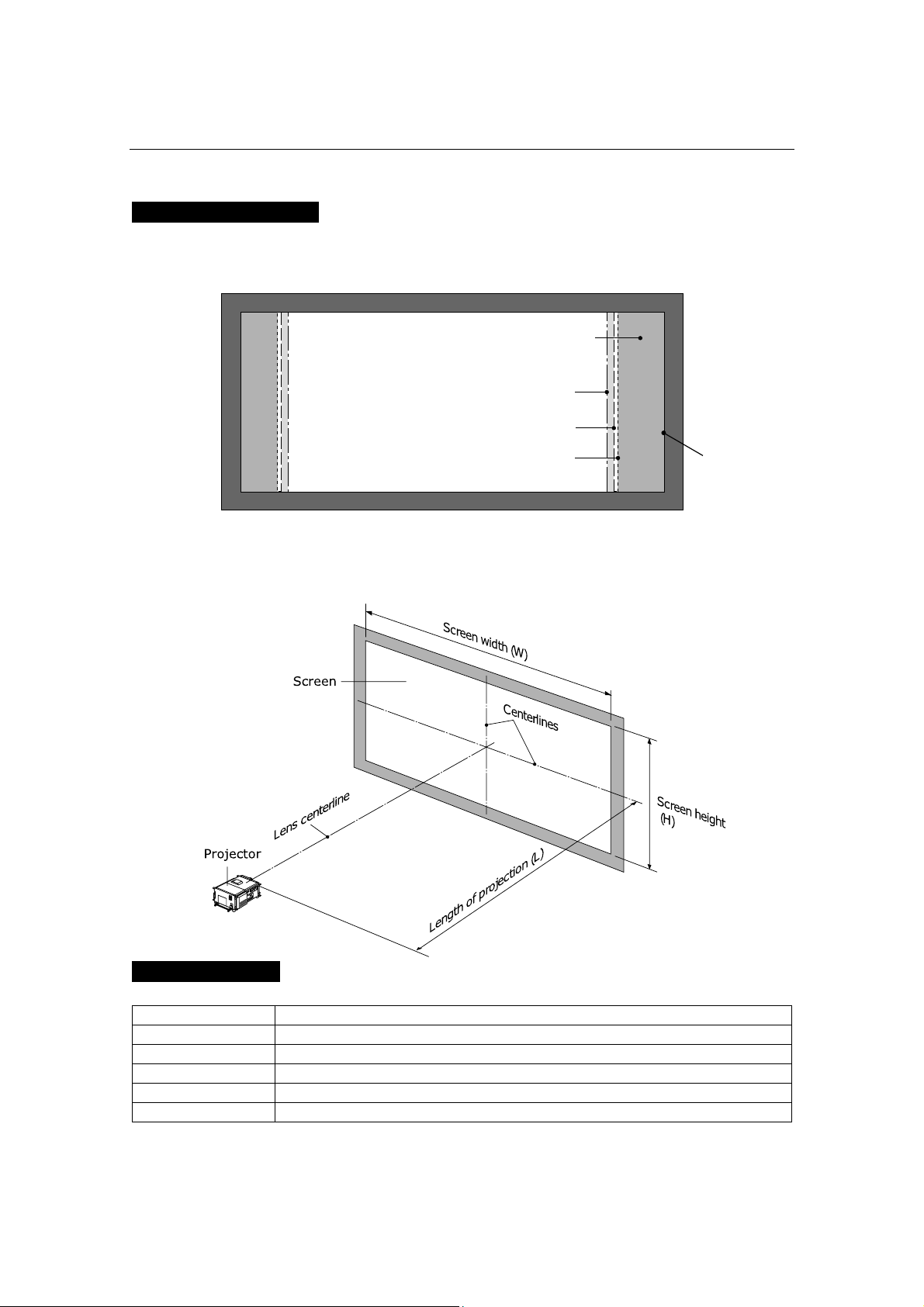
This section provides guideline information on how to
select a screen size and projector mounting position
appropriate for your presentation purposes and about
selection of types of lenses as well. Select primary/
anamorphic lenses for your projector according to the
environment in which it is installed.
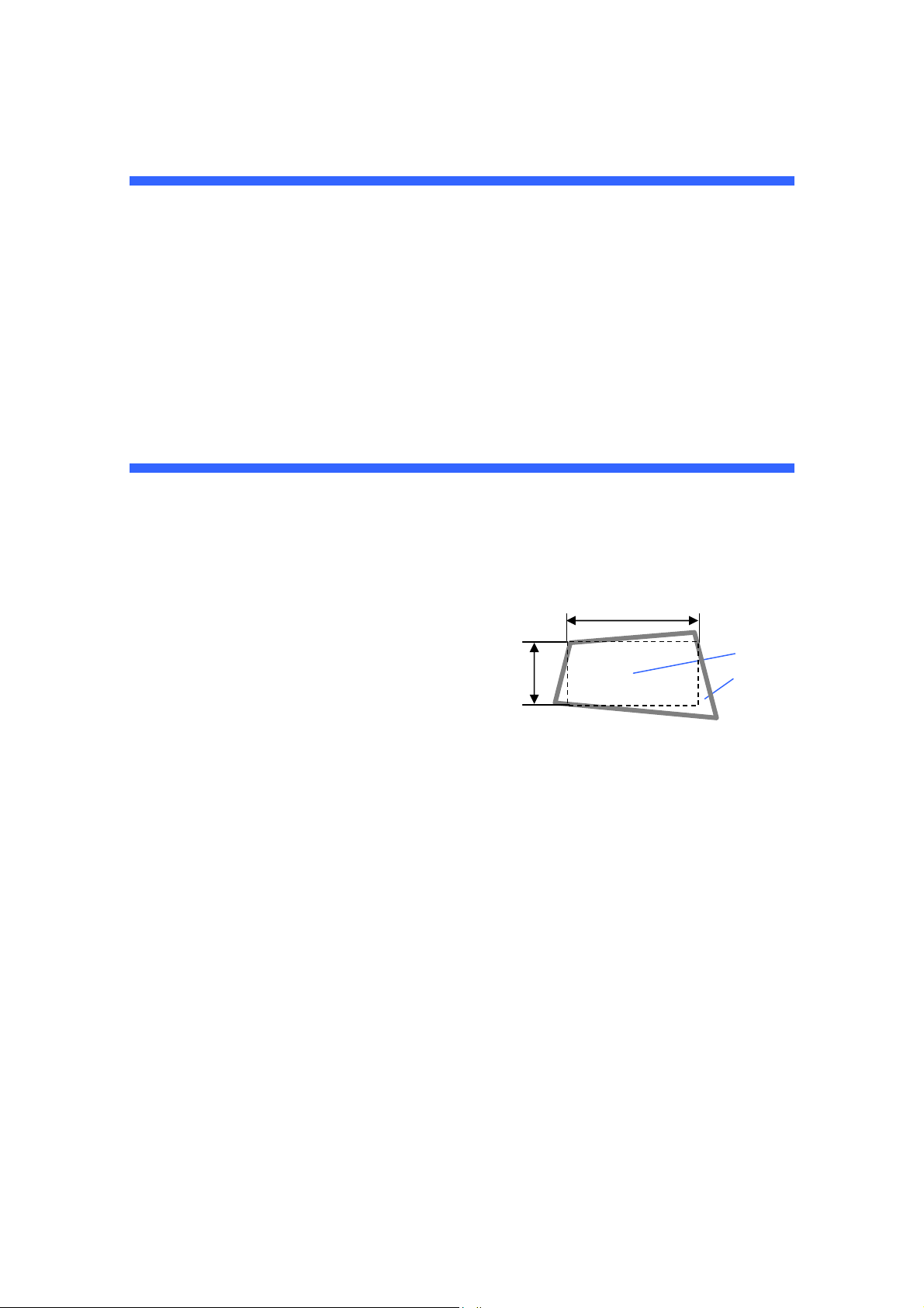
Note that all descriptions given in this manual assume that
the angle of projection is zero degree. In case of
projection from an upper position or from the right or left,
it is necessary to calculate the width for the minimum
projected image that is a little larger than the screen size.
Screen
Width of minimum
Projected
image
NC800C 1. Before Setting Up Your Projector
E-9
1.2 Screen Type
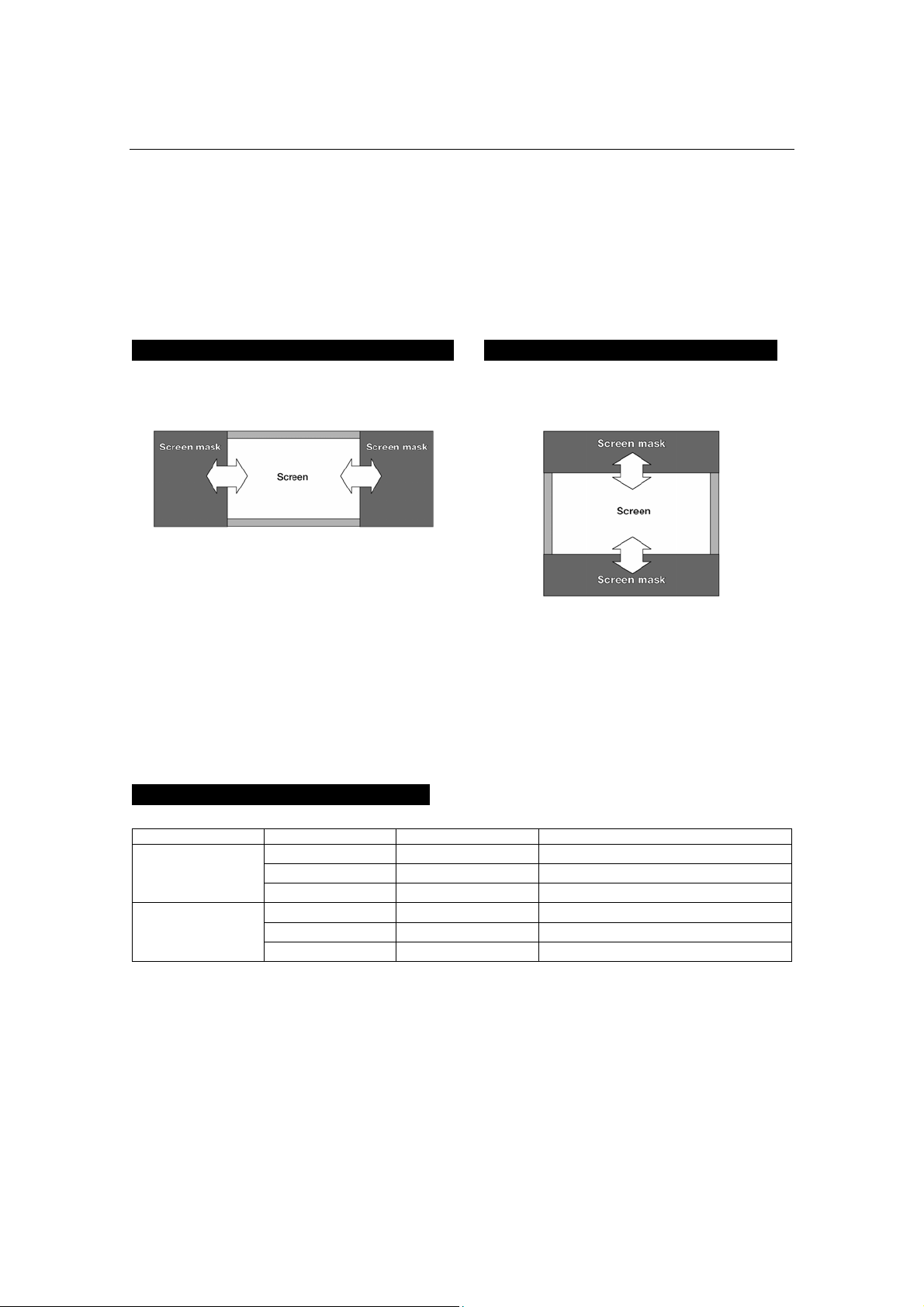
The following two types of screen masks can be used for the DLP Cinema Projector. Check
the screen mask for your projector for its type before selecting lenses because types of
primary/anamorphic lenses to be used on the projector and its settings depend upon the
type of screen mask you use.
Horizontal moving screen mask
Screen masks move horizontally to
adjust the screen.
Vertical moving screen mask
Screen masks move vertically to adjust the
screen.
1.3 Selecting of Anamorphic Lenses
An anamorphic lens is required when you use a wide screen for projection. Because a
different type of anamorphic lens should be used according to the type of projector and
screen, determine an appropriate anamorphic lens in consultation with the end user,
considering its application purpose. See the table below for available anamorphic lenses.
Available Anamorphic Lenses
Screen mask type Screen Type Projected area Anamorphic lens
SCOPE 2048 x 1080
x1.25
VISTA (FLAT) 1998 x 1080
-
Horizontal moving
HDTV
1920 x 1080
-
SCOPE 2048 x 1080
x1.25 or None
(*)
VISTA (FLAT) 1998 x 1080
-
Vertical moving
HDTV
1920 x 1080
-
(*) If the screen mask is of vertical moving type and the image cannot be enlarged
vertically due to insufficient zooming magnification of the primary lens, do not use the
anamorphic lens for projection. In this case, it is necessary to set the Screen file
(Screen Presentation Setting). For the Screen file, refer to “Creating a Screen File” in
"Installation and Adjustment Manual (Touch Panel)”.
NC800C 1. Before Setting Up Your Projector
E-10
Projected Images
The anamorphic lens works to magnify projected images horizontally when you use a wide
screen for projection (SCOPE).
1.4 Selection of Primary Lens
Option lenses
MODEL Magnifying
L2K-12ZM 1.25- 1.45
L2K-14ZM 1.45 - 1.8
L2K-18ZM 1.8 - 2.4
L2K-22ZM 2.2 - 3.0
L2K-30ZM 3.0 - 4.3
Screen
Area magnified by anamorphic lens
HDTV
Projected area, 1920 x 1080
VISTA (FLAT)
Pro
j
ected area
,
1998 x 1080
Pro
j
ected area
,
2048 x 1080

NC800C 1. Before Setting Up Your Projector
E-11
How to Calculate the Magnification of Primary Lens
SCOPE projection:
Length of projection (L)
Primary lens
magnification =
Screen width (W) ÷ Anamorphic lens magnification
Use 1x for anamorphic lens magnification if this lens is not in use.
VISTA (FLAT) /HDTV projection:
Length of projection (L)
Primary lens
magnification =
Screen width (W) × (2048 ÷ Number of pixels per horizontal line)
* Number of pixels per horizontal line: 1998 for VISTA (FLAT); 1920 for HDTV
* Select a lens that meets the magnification requirement for both SCOPE and VISTA
(FLAT)/HDTV screen types.
Example of Primary Lens Calculation
If the projection distance (L) = 16 m, the screen width (W) = 8 m and the anamorphic
lens is not used:
16m
SCOPE projection =
8m÷1
= 2.0x
16m
VISTA (FLAT) projection =
8m×(2048÷1998)
= 1.95x
16m
HDTV projection =
8m×(2048÷1920)
= 1.88x
Therefore, "L2K-18ZM", which satisfies the magnifications in all of the above projections,
is selected as the primary lens.

NC800C 1. Before Setting Up Your Projector
E-12
1.5 List of Tools Used
The tools used for NC800C installation are as follows:
Item Tool Quantity Major Application
Phillips head screwdriver (No.2) 1 Covers Projector
(NC800C)
Flat head screwdriver 1 Lens
Hexagonal wrench (Width across flats: 4 mm) 1 Lamp house
Phillips head screwdriver (No.2) 1 -
Hexagonal wrench (Width across flats: 3mm) 1 -
Hexagonal wrench (Width across flats: 5mm) 1 Front bracket, Lens
holder
Anamorphic stand
(AS1.25/AS1.25-E)
Hexagonal wrench (Width across flats: 6mm) 1 Shaft L/R
Phillips head screwdriver (No.2) 1 -
Flat head screwdriver (3mm) 1 Connector
Touch panel
controller
(NC-TP6402)
Holder arm
(NC-TH6403)
Hexagonal wrench (Width across flats: 5mm) 1 Outer panel of the
projector
Lens Hexagonal wrench (Width across flats:
2.5mm)
1 Lens adaptor
E-13
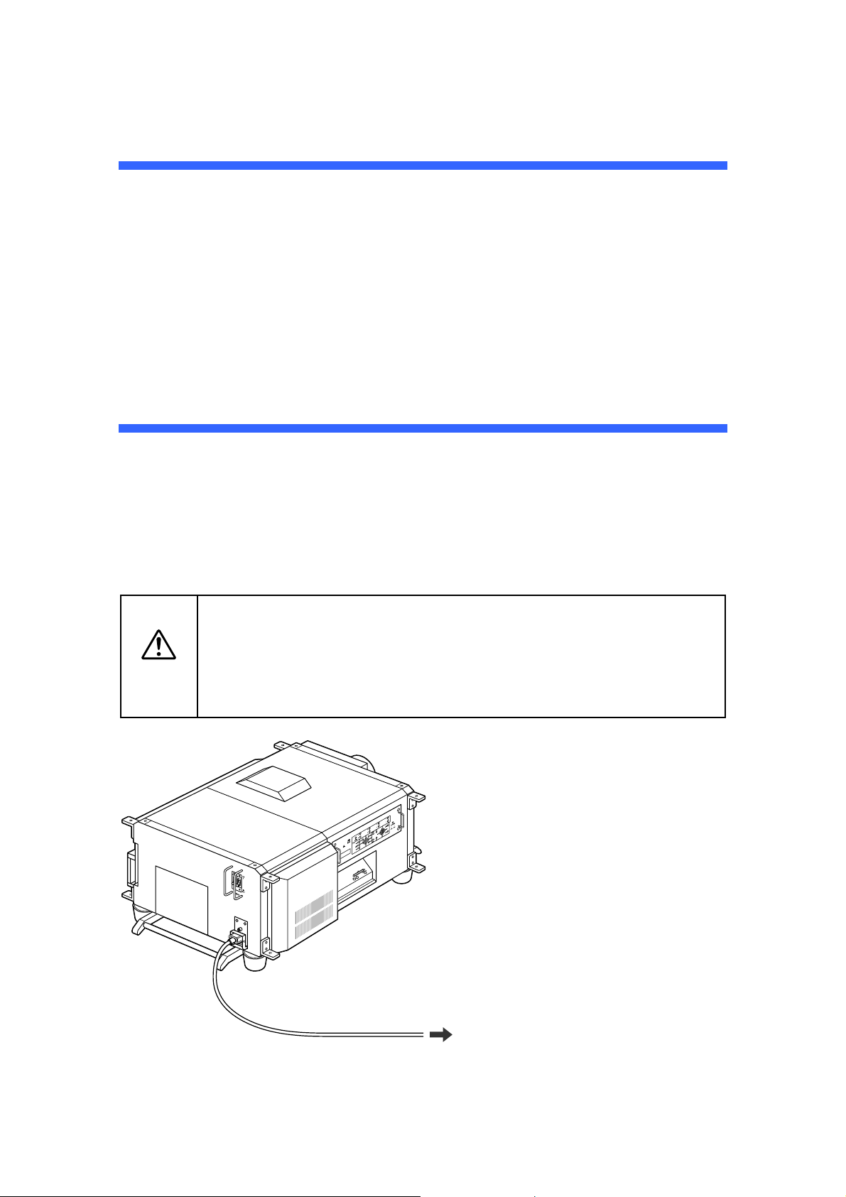
2.
Setting Up Your
Projector
2.1 Connecting the Power Cord
After making sure that the main power switch of your projector is turned off, plug its power
cord into an earthed, three-pin power outlet (power supply: 100-120 VAC or 200-240 VAC).
Caution
• Consult your dealer for installing the power cable to the projector. Do not
install the power cable by yourself.
• For equipment safety, be sure to provide ground connection. To prevent
the risk of electric shock, grounding must be conducted by a qualified
electrician. Make sure to connect the grounding conductor before plugging
the power connector.
Plug to a 100-120 VAC or 200-240 VAC
three-pin power outlet.
NC800C 2. Setting Up Your Projector
E-14
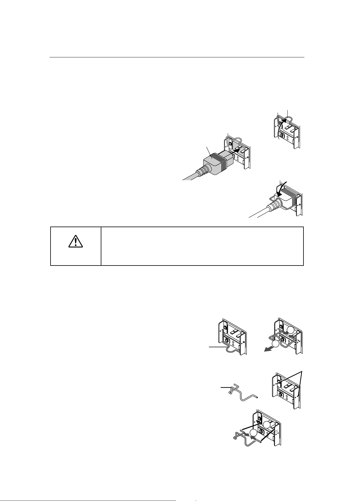
2.1.1 Be sure to secure the power plug as follows:
(To prevent falling out)
[1] Lift the wire stopper.
[2] Plug the projector's power
cord into the wall outlet.
[3] Bring the wire stopper
down to secure the power
plug.
Caution
In order to protect the projector from being damaged, DO NOT unplug the
projector's power cable from the wall outlet:
immediately after the cooling fan stops working (the fan continues working for 3
minutes after the projector is tuned off); and while a flash memory card is in use
(the memory data could be destructed).
2.1.2 When Using an EU Type Power Cable
Replace the attached wire stopper with the EU-spec. one supplied with the projector,
following the steps below:
[1] Remove the attached
Japan/US-spec. wire
stopper.
1
2
[2] Mount the EU-spec. wire
stopper.
2
1
Wire stopper
Power plug
Japan/US-spec.
wire stopper
Use these holes to
mount the EU type wire
stopper.
EU-spec. wire
stopper
NC800C 2. Setting Up Your Projector
E-15
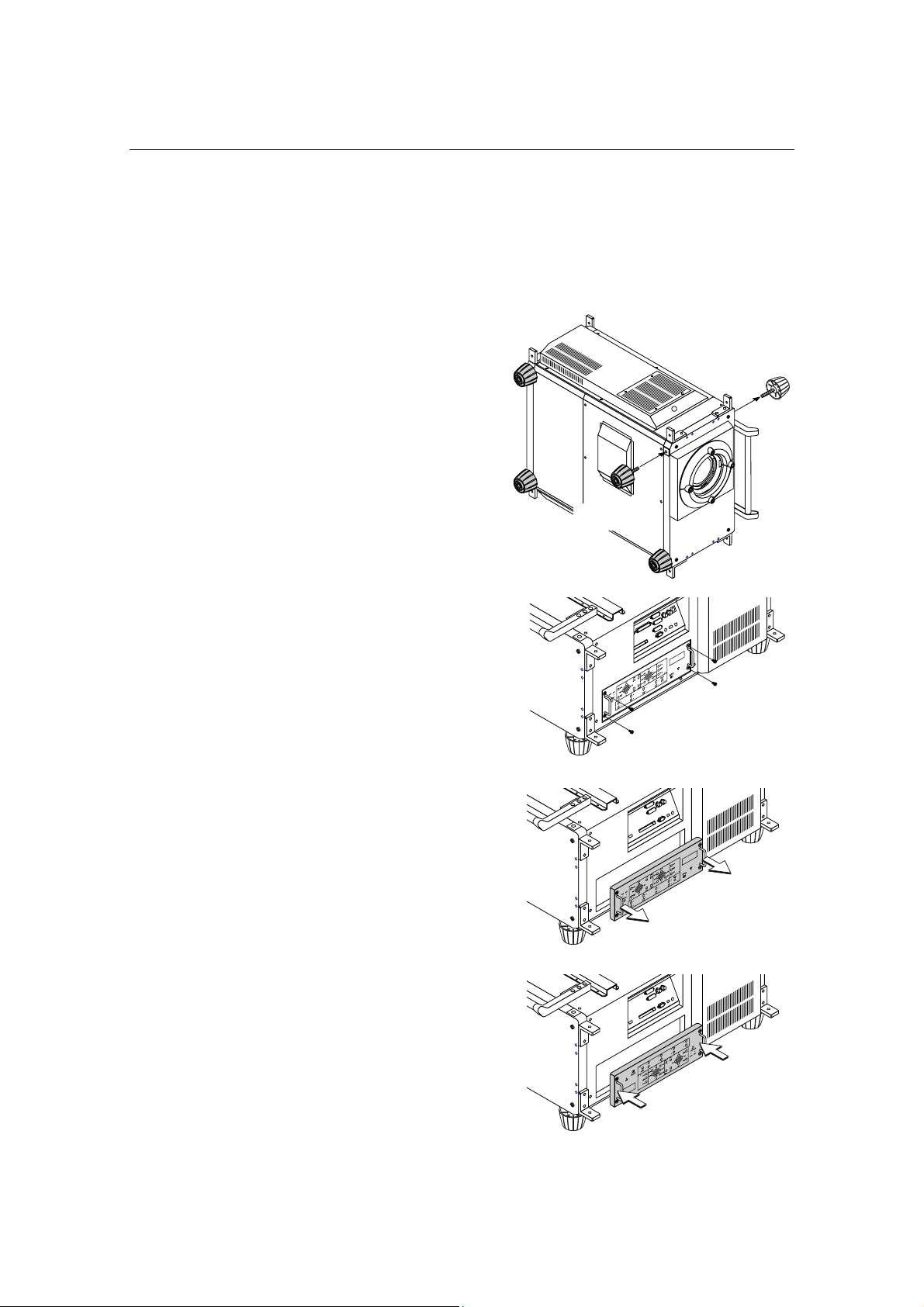
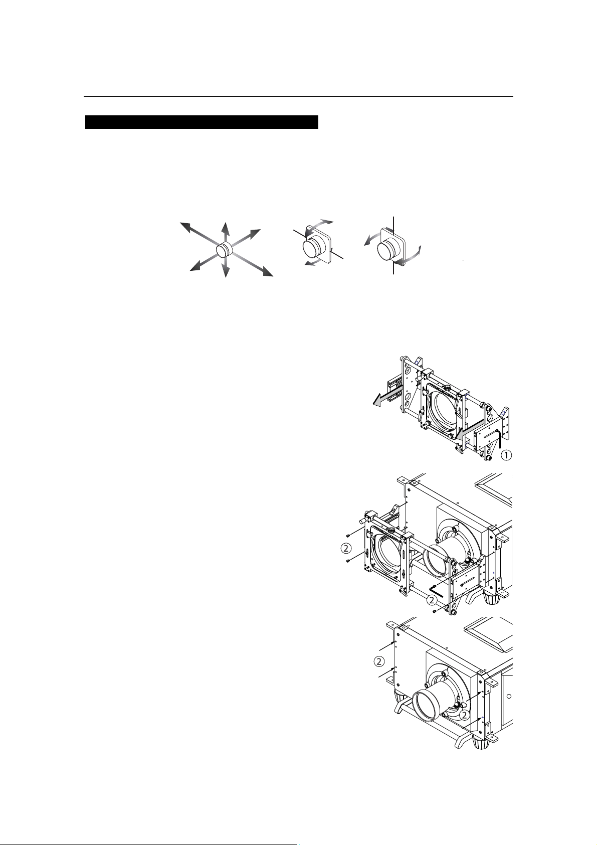
2.2 Setup Required for Overhead Installation
The DLP Cinema Projector has been shipped as a Desktop Front type “Normal-F” from our
factory. If you want to have the projector installed overhead or on the ceiling, you must
change the mounting orientation of the control panel located at the side of the projector.
[1] Change the position of the
projector stays as
illustrated on the right.
You can remove them by turning
counterclockwise.
[2] Remove the four screws
clamping the control panel
located on a side panel of
the projector.
[3] Hold the control panel
handles and gently pull the
panel off.
[4] Turn the control panel
upside down (180 degrees)
and gently insert into the
projector.
Attach
Remove
NC800C 2. Setting Up Your Projector
E-16
[5] Tighten the four screws
previously removed to
remount the panel.
NC800C 2. Setting Up Your Projector
E-17
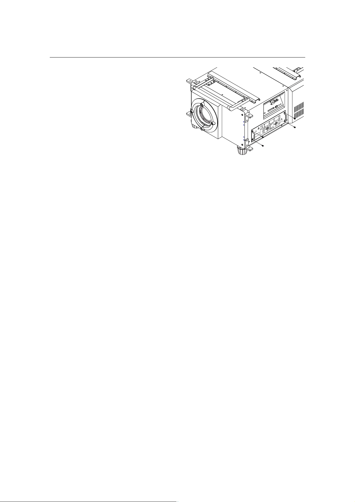
2.3 Mounting the primary lens
Mount the attached lens holder (NC-50LA01) before mounting the primary lens to the
projector.
[1] Remove two mounting
metals of the lens holder.
Remove four mounting screws and
remove two mounting metals.
These four mounting screws and two
mounting metals will be used for lens
holder mounting.
[2] Place the lens with the face
upward.
Check that the place for putting the lens
is flat before the work.
It is recommended to keep the lens cap
set so as to protect the lens from any
damage.
[3] Insert the lens holder from
under the lens.
Align the lens holder slits with two lens
insertion guides and insert the lens
holder.
[4] Fix two mounting metals of
the lens holder with four
mounting screws.
Mounting metals
Lens Holder
Slit
lens
insertion
guides
NC800C 2. Setting Up Your Projector
E-18
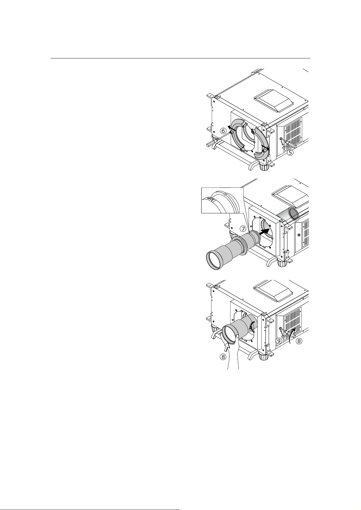
[5] Remove the rubber cap that
covers the primary lens
setscrew located on the
side panel of the projector.
Use a slotted screwdriver to
untighten the setscrew.
[6] Loosen the screws on both
sides of the lens hood to
remove the hood pieces
sideways.
[7] Holding the primary lens
unit with its guide notch up,
insert it into the projector
until it cannot go further.
[8] While slightly pushing the
lens unit up, retighten the
lens setscrew previously
loosened.
[9] Replace the setscrew
rubber cap to its place.
NC800C 2. Setting Up Your Projector
E-19
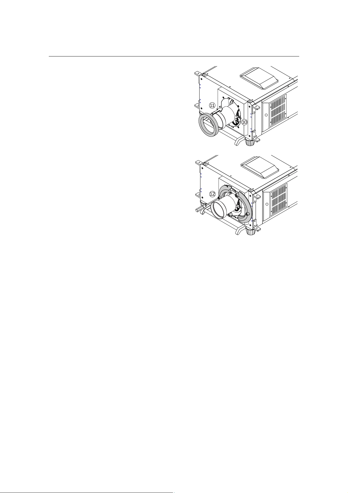
[10]
Attach the lens control
connector.
[11] Attach the dust prevention
cover (sponge), supplied
with the projector, to the
lens unit.
[12] Remount the lens hood
pieces.
NC800C 2. Setting Up Your Projector
E-20
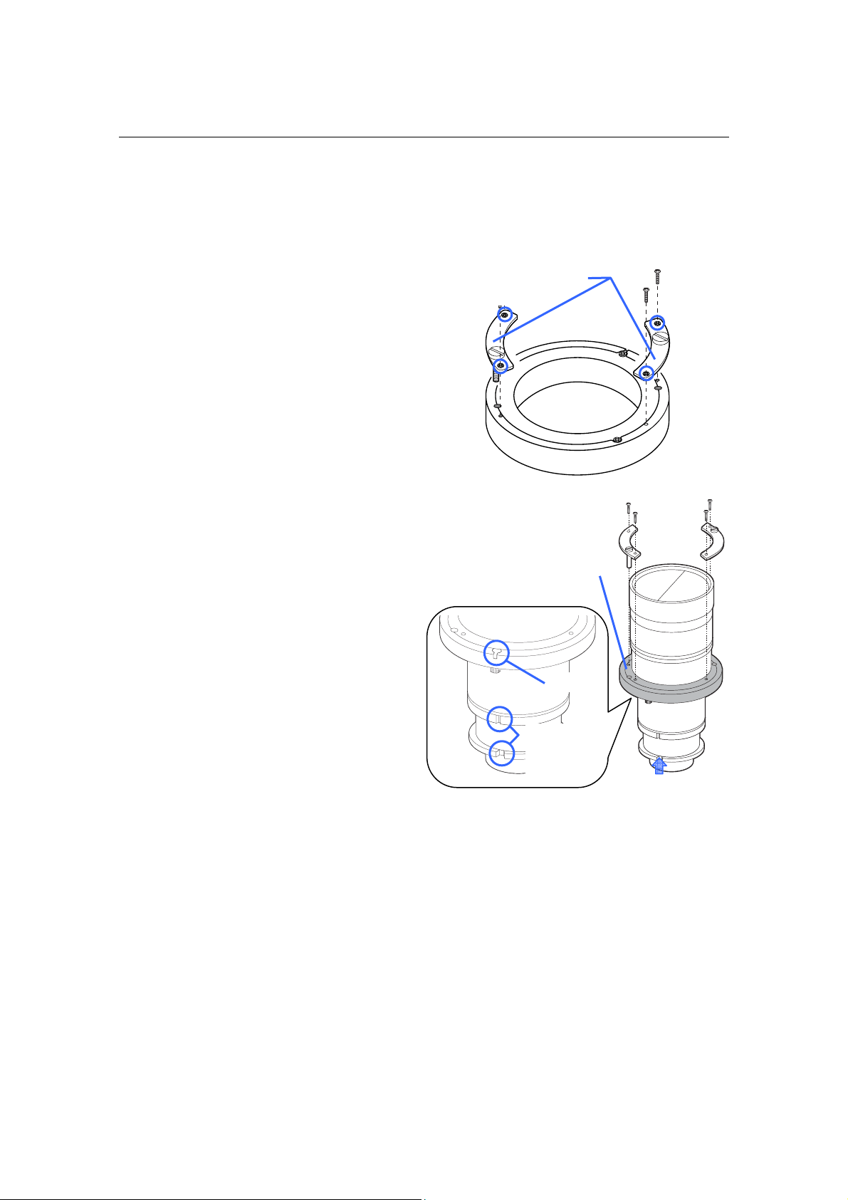
2.4 Mounting the Anamorphic Lens and Its Holder
An optional 1.25x anamorphic lens Model AL1.25/AL1.25-E are required for film projection in
a wide-screen, CinemaScopic movie format on the DLP Cinema Projector Model NC800C. A
dedicated, stand-type anamorphic lens holder Model AS1.25/AS1.25-E are optionally
available for mounting this lens. See also the instruction manual for the lens holder.
Names of the Components
X-direction operating grip
Y-direction adjusting knob
X- direction fixing lever
X-direction to
pp
er
Tilt angle
ad
j
ustin
g
knob
Z-direction
setscrew
Y-direction
setscrew
Pan angle adjusting/
fixin
g
screw
(
P2
)
Pan angle adjusting/
fixing screw (P1)
Anamorphic lens holder screw
Tilt an
g
le fixin
g
screw
Z-direction
setscrew
NC800C 2. Setting Up Your Projector
E-21
Indication of Adjustment Directions
The following arrows are used in this manual to indicate the moving and rotating directions
of the lens unit.
noitcerid-X
)latnoziroH(
noitcerid-Z
)lanidutignoL(
noitcerid-Y
)lacitreV(
elgna naP
)noitator laretal(
elgna tliT
)noitator lacitrev(
Preparation:
Get the supplied Allen wrench and screws (hexagon socket head cap screws) ready.
[1] Loosen the z-direction
setscrews located at either
side of the lens holder. Extend
the side plates toward the
depth as far as they will go,
then retighten the setscrew on
each side.
[2] Using the enclosed four Allen
screws (M8 hexagon socket
head cap screws), mount the
anamorphic lens holder to
your projector housing with its
orientation as illustrated
below.
Shown in Fig. 1 below are the tapped holes to
be used for mounting the lens holder when
you want to have the projector lens 'look
down' while keeping the film plane vertical,
with (or without) the use of lens shift feature.
Shown in Fig. 2 below are the tapped holes to
be used for mounting the lens holder when
you want to have the lens 'look up' while
keeping the film plane vertical, with the use
of lens shift feature.
[Fig. 2]
[Fig. 1]
NC800C 2. Setting Up Your Projector
E-22
[3] Slide the anamorphic lens
mount toward the side where
it does not come in front of
the primary lens of the
projector. Lock the levers to
fix the mount.
To slide the lens mount, turn the x-direction
fixing levers counterclockwise to unlock them.
After sliding, lock the levers to fix the mount.
[4] Untighten the M6 hexagon
head screw for anamorphic
lens mount. Mount the
anamorphic lens to the mount
with its orientation as
illustrated below, then
retighten the mount screw.
M6 hexagon head screw for
anamorphic lens holder
NC800C 2. Setting Up Your Projector
E-23
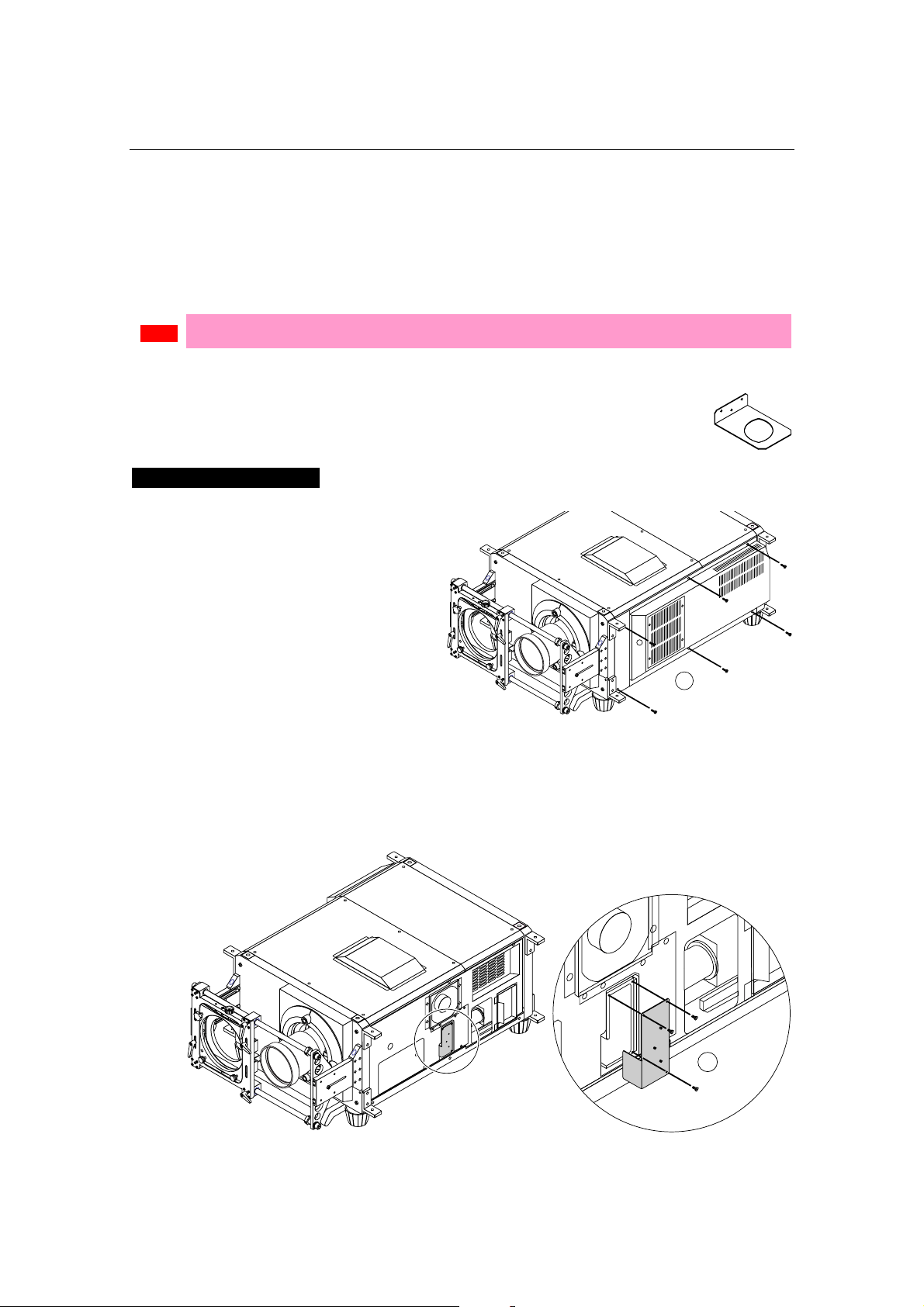
2.5
Installation of Small Iris
(Information for Service Personnel)
If it is requested by the customer to reduce the projector's lamp luminance because it is too
bright even when set to the minimum level, you may reduce it as follows. This operation will
also improve the contrast ratio.
Note
• With the small iris installed, the automatic luminance adjustment [Auto] will be disabled.
Preparation:
• Make sure that the main power switch of the customer's projector is turned off.
• Get the supplied small iris ready. (Included in the standard set of accessories)
Installation Steps
[1] Remove the side panels
from the projector.
Untighten the six clamping screws to
remove them.
1
[2] Remove the holder panel
of the engine block by
untightening the three
setscrews.
2
NC800C 2. Setting Up Your Projector
E-24
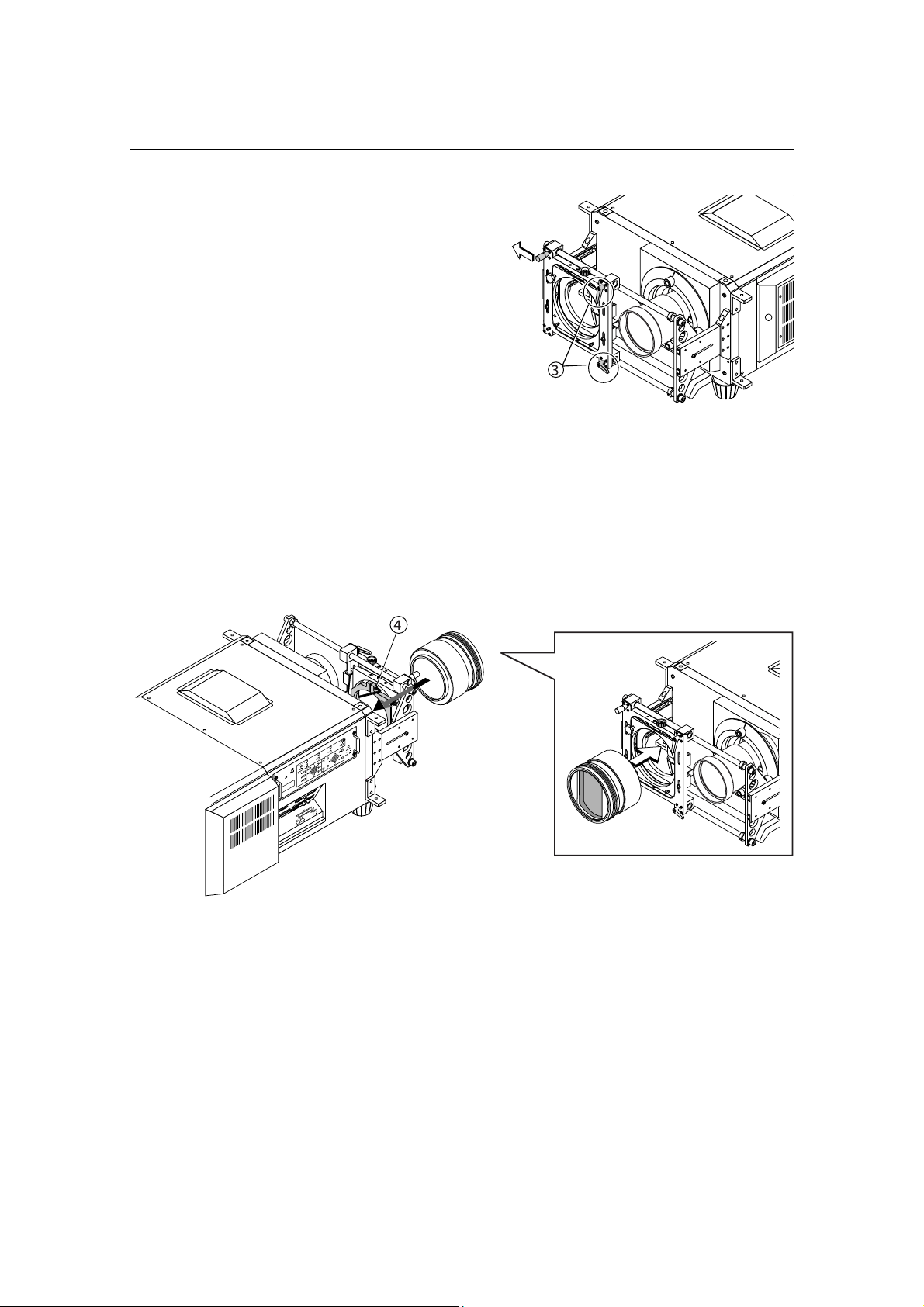
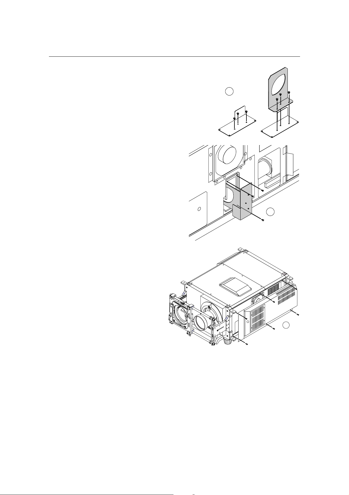
[3] Remove the holder panel
setscrews completely
and attach the supplied
small iris to the panel,
using the removed
screws.
3
[4] Remount the holder
panel now attached with
the iris to the engine
block.
Use three screws you have removed
at Step 2 to mount the iris plate.
4
[5] Replace the side panels
to their place.
5
NC800C 2. Setting Up Your Projector
E-25
2.6 Affixing the security label
When the projector of FIPS correspondence is used, the following procedure is not necessary.
Upon completion of installation and mounting of all parts, affix the security label when
mounting the cover of the projector. For affixing of the security label, refer to the supplement
sheet attached to the projector.
Tips
• When the touch panel controller (separately available) or the incorporated multimedia
switcher (separately available) is mounted, affix the security label after completion of these
parts.

E-26
3.
Connecting to the
Projector
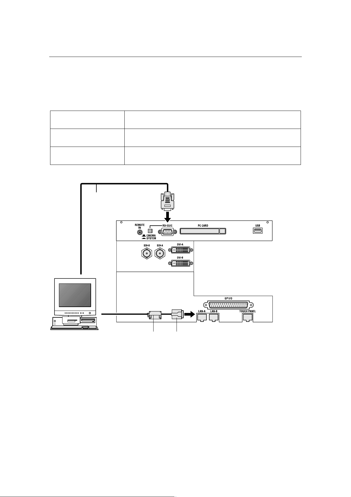
3.1 Connecting the image input
Your projector has four image input terminals, namely, the HDSDI A input terminal, the
HDSDI B input terminal, the DVI-D A input terminal, and the DVI-D B input terminal.
HDSDI A/B input terminal
(SDI A/SDI B)
Inputs serial digital images from a Video Server or Video
source.
DVI-D A/B input terminal
(DVI A/DVI B)
Inputs digital RGB signals from a PC.
DVI-D signals cable
75Ω coaxial signal
cable
NC800C 3. Connecting to the Projector
E-27
3.2 Connecting the various control terminal
For control, your projector comes with such ports as the PC control terminal and the Ethernet
port (RJ-45).
PC control terminal
(PC CONTROL)
Use this terminal when controlling the projector in serial
connection from a PC.
Ethernet port
(LAN 1/LAN 2)
Use this port when controlling the projector in LAN connection
from a PC.
Touch panel port
(TOUCH PANEL)
Use this to use the touch panel controller (separately sold).
RS-232C
LAN cable
Ferrite core (appending)
NC800C 3. Connecting to the Projector
E-28
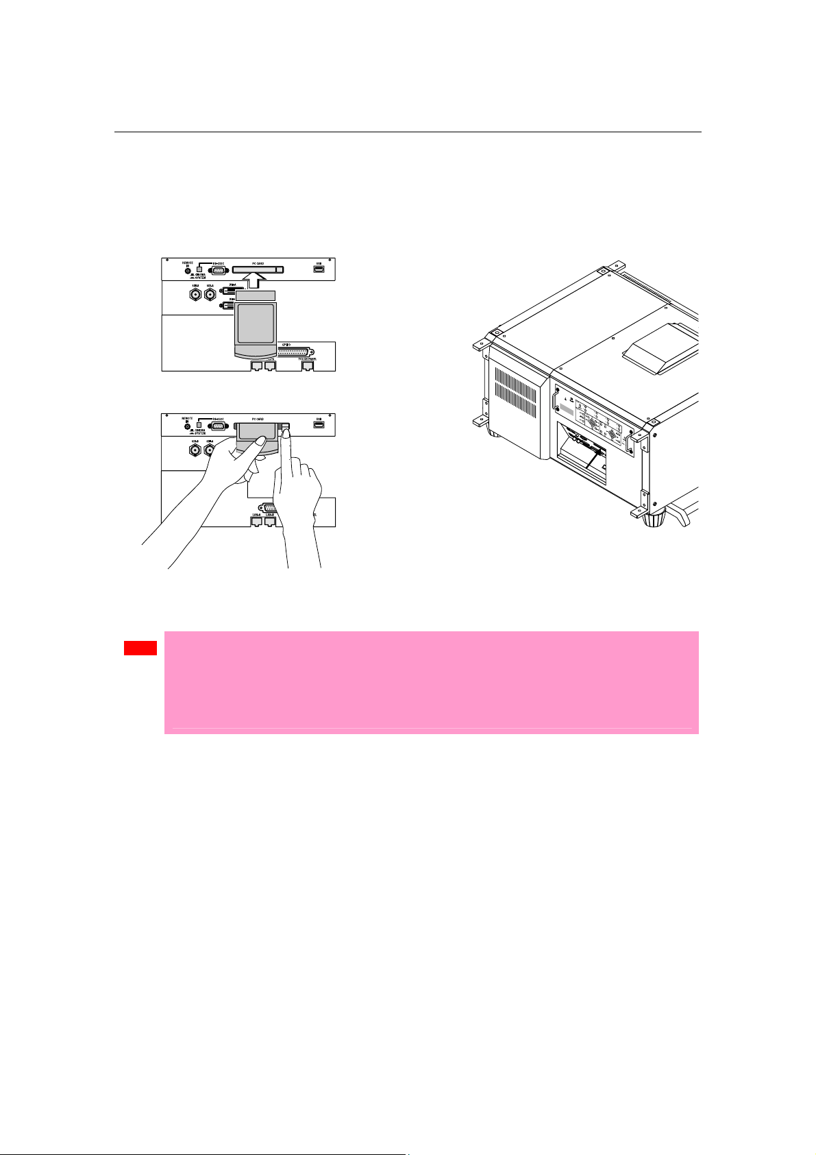
3.3
Controlling Your Projector Using a Wireless LAN Card
When using a wireless LAN to control the projector, please insert a wireless LAN card
(available separately) into the Connection terminal PC Card slot located at the projector side.
Note
• If the wireless LAN card is in use, NC800C cannot be controlled from the incorporated LAN
port (LAN A/LAN B). The Cinema circuit can be controlled even if the wireless LAN is in
use.
• Be sure to set or remove your wireless LAN card only when the power to your projector is
off. Insertion or removal of a wireless LAN card when power to your projector is on may
result in a destruction of the wireless LAN card.

E-29
4.
Projector Adjustment
4.1 Setting the projector projection method
When the projector is shipped from the factory, the projection method is set to the front
mode (projection from the front of the screen with the projector installed on the pedestal).
It is necessary to use the remote controller for change of the projection method. Refer to the
operation manual for remote controller operation
[1] Press the “TEST” button while holding down the “CTL” button on
the remote control panel.
The Passcode input screen appears on the LC display located on the projector's side panel.
[2] Enter your passcode* using the numeric character keys of the
remote control.
After authentication of your passcode, the Configuration menu will become active.
* Contact your dealer for your specific passcode.
[3] Use the arrow buttons “ / ” to select "Configuration" and press
the button.
[4] Use the arrow buttons “ / ” to select "Installation" and press
the button.
[5] Check that “Image Orient” is selected and press the button.
If “Image Orient” is not selected, press the “ / ” buttons to select it
[6] Press the “ / ” buttons to select the projection method (Image
Orientation).

NC800C 4. Projector Adjustment
E-30
When shipped from the factory, it is set to [Normal-F].
- Normal-F: Front projection. With the projector installed on the pedestal, projection is
executed from the front of the screen.
- UpsideDown-F: The projector body is installed upside down, and projection is made from front
of the screen.
- Normal-R: Rear projection. With the projector installed on the pedestal, projection is
executed from the back of the screen.
- UpsideDown-R: The projector body is installed upside down, and projection is made from
behind the screen.
[7] Press the “ENTER” button.
An (*) will be put on the selected projection method (Image Orientation).
[8] Press the “EXIT” button several times.
The projector exits the menu and goes back to the regular screen.
4.2 Adjusting the primary lens
Display the test pattern and adjust the screen size, focus and screen position with the
primary lens.
4.2.1 Display the test pattern
[1] Press the “MENU button” of the remote controller.
"Title Select" is displayed on the LCD screen at the projector side.
[2] Press “ ” button.
[3] Press the “ / ” buttons to select "TEST Pattern".
[4] Press “ ” button.
[5] Use the “ / ” buttons to select the "TEST Pattern name" which
it projects, and press “Enter” button.
An (*) will be put on the selected projection method.
To cancel the display of the test pattern, select the projection signal again or select “OFF” of the
test pattern.
NC800C 4. Projector Adjustment
E-31
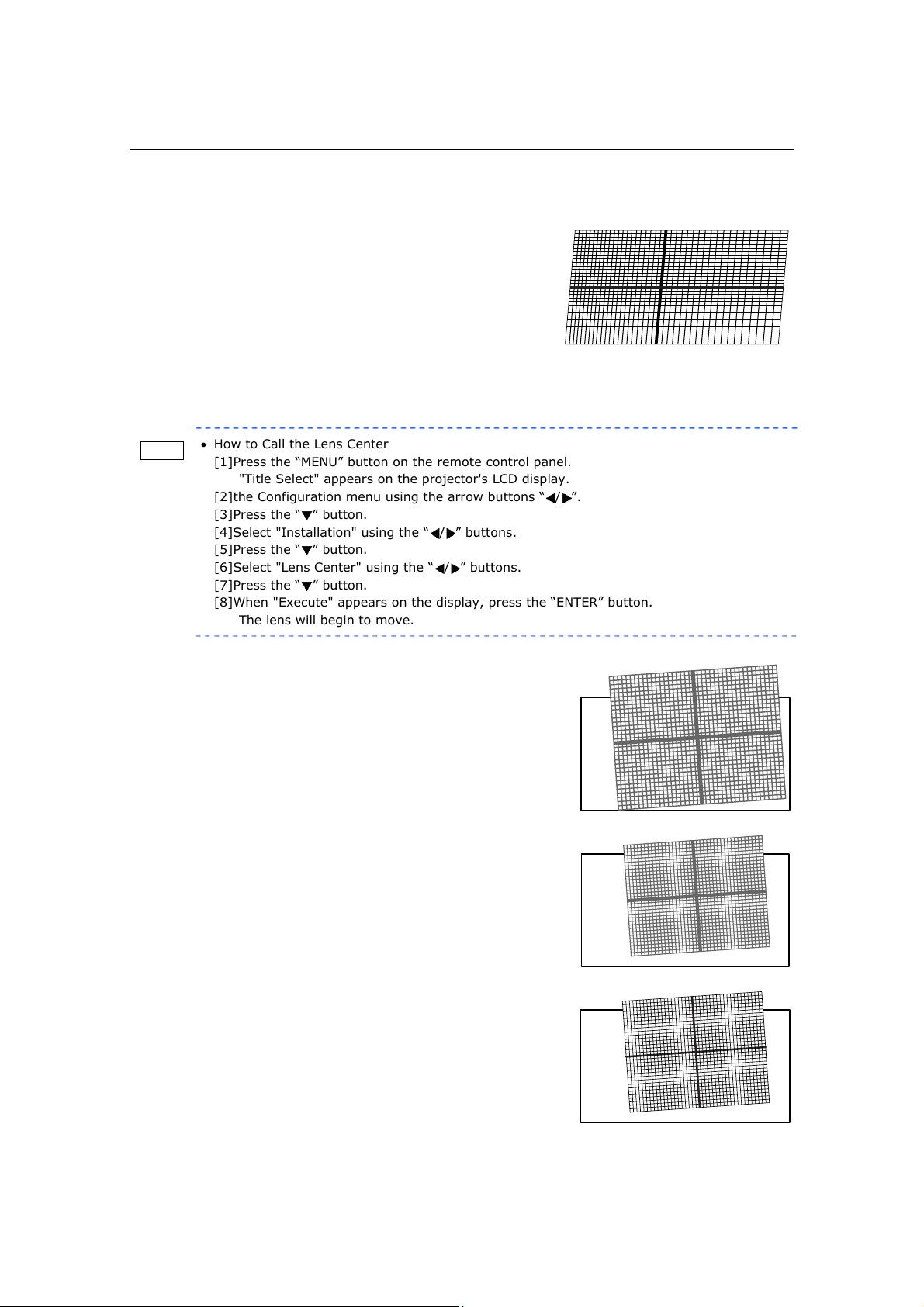
4.2.2 Adjusting the screen ratio
Adjust the screen ratio of the primary lens here.
When an anamorphic lens is used, distortions will be
produced on the projection screen. To prevent the image
from being cut off due to these distortions, the image size
should be made larger than the screen size beforehand.
To minimize potential distortions of the anamorphic lens, it
is recommended that the lens shift not be used as much as
you can and that projection be kept at lens center.
Memo
• How to Call the Lens Center
[1]Press the “MENU” button on the remote control panel.
"Title Select" appears on the projector's LCD display.
[2]the Configuration menu using the arrow buttons “
/ ”.
[3]Press the “
” button.
[4]Select "Installation" using the “
/ ” buttons.
[5]Press the “
” button.
[6]Select "Lens Center" using the “
/ ” buttons.
[7]Press the “
” button.
[8]When "Execute" appears on the display, press the “ENTER” button.
The lens will begin to move.
[1] Press the “ZOOM+-” buttons on the
remote control panel or of the
projector to roughly adjust the
screen size so that the screen height
and the image height are the same.
[2] Press the “FOCUS+-” buttons of the
remote control or the projector to
roughly adjust the focus.
[3] Adjust the surface on which the
projector is set up and the tilt foot of
the projector to adjust the setup
position, height, and tile (front-back
and left right) of the projector so
that the projected image is level at
the screen center.
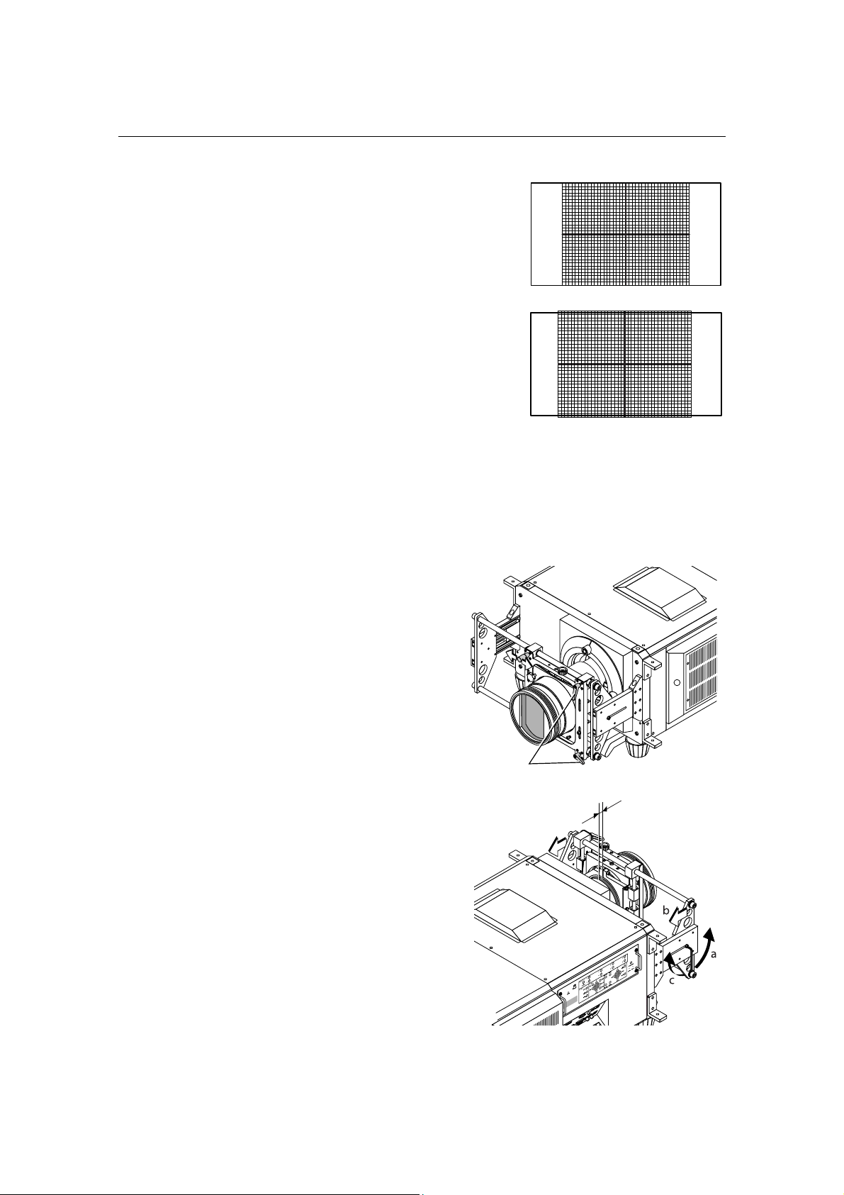
NC800C 4. Projector Adjustment
E-32
[4] Use the “ZOOM+-” buttons again to
adjust the screen size so that the
projected image is kept 0.5 to 1
crosshatch cell portions higher than
the top edge of the screen.
[5] Finally adjust the focus using the
“FOCUS+-” buttons either of the
remote control or the projector.
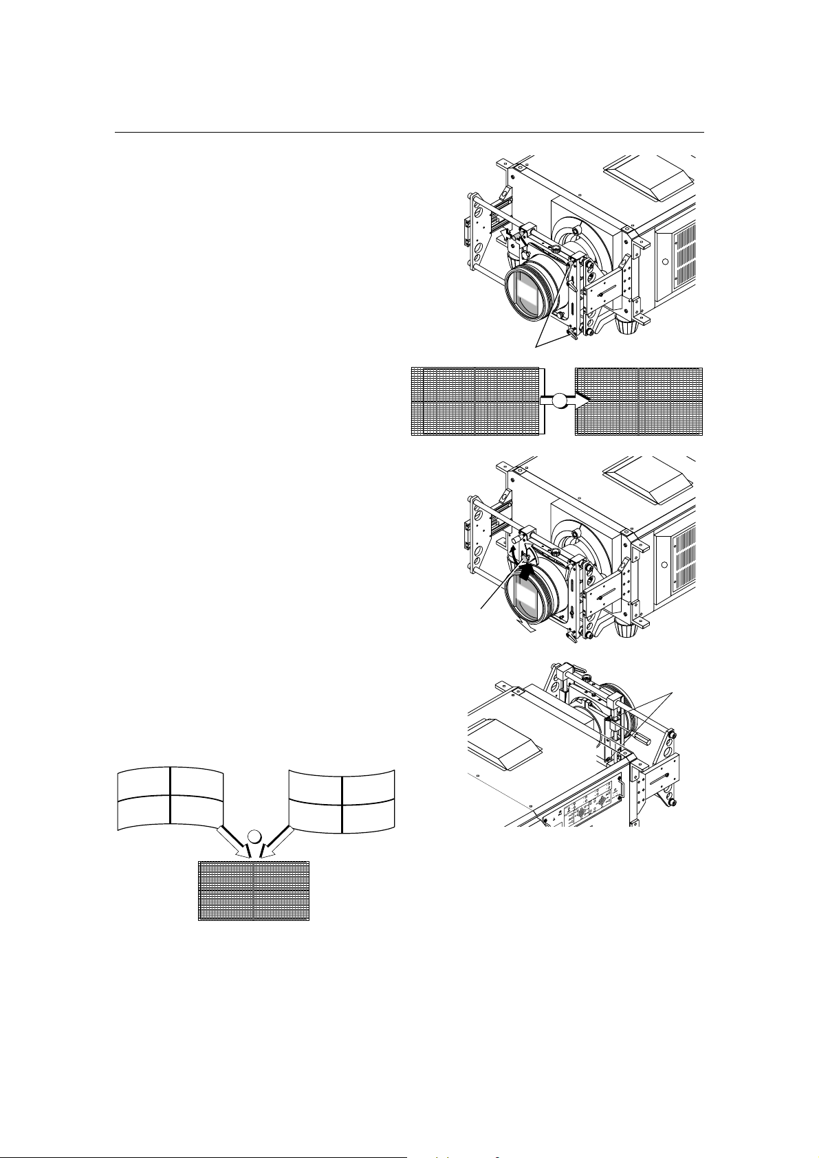
4.3 Adjusting the anamorphic lens
Here, you will adjust the positions (vertical and horizontal positions and depth) of the
anamorphic lens, and its rotation, tilt/pan angles and focusing as well.
[1]
Move the anamorphic lens mount
(of the holder) until it comes in
front of the primary lens of the
projector. Temporarily lock the
x-direction fixing levers to fix the
mount.
[2]
Loosen the right and left hexagon
head screws of the anamorphic
lens holder and move the
anamorphic lens so that the
clearance between this and the
primary lens is minimized.
Tighten the side hex screws.
x-direction
fixing levers
NC800C 4. Projector Adjustment
E-33
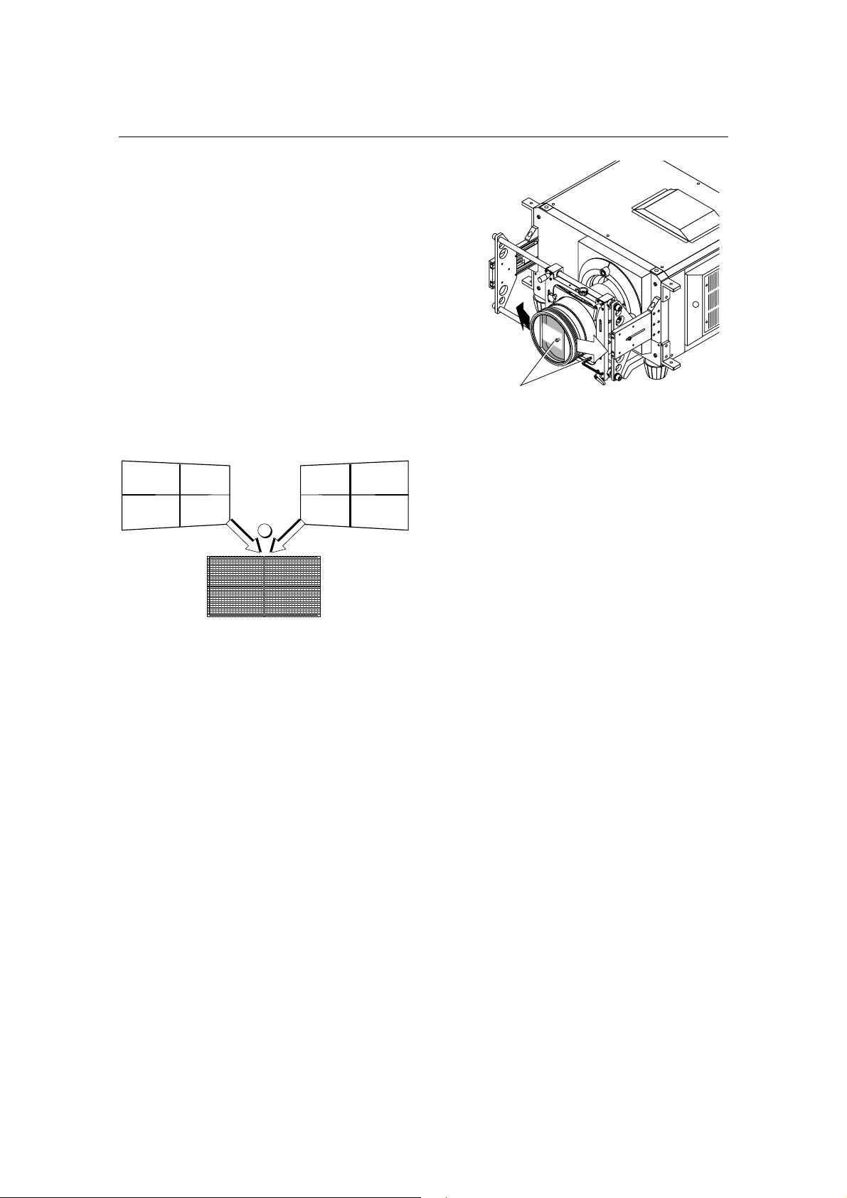
[3]
Loosen the anamorphic lens
setscrew (hexagon head screw)
and turn the lens unit so that the
vertical and horizontal lines of the
center of the image projected
become perpendicular and level.
(To prevent the anamorphic lens from
coming off, be sure to hold the lens while
loosening the setscrew.)
3
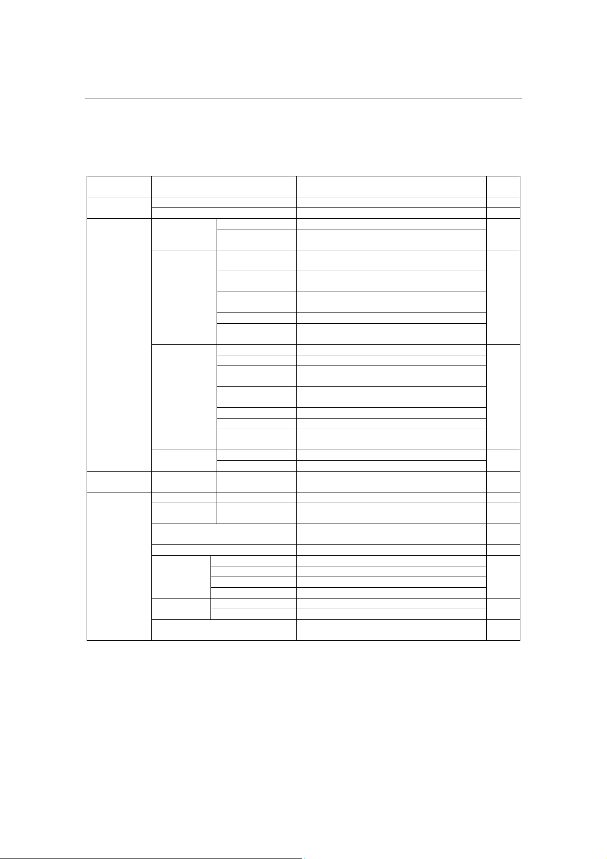
[4] Loosen each of the two
y-direction setscrews of the
anamorphic lens holder and
turn the y-direction adjusting
knob on the top to adjust the
lens position so that the
image is projected through
the center of the anamorphic
lens. Securely tighten the two
setscrews after adjustment.
a, c
b
4
NC800C 4. Projector Adjustment
E-34
[5]
Unlock the x-direction fixing
levers to adjust the lens position
so that the image is projected
through the center of the
anamorphic lens. Securely
lock the levers after adjustment.
(The image center on the screen must
match with and without the anamorphic
lens.)
5
[6] Loosen the two tilt angle
fixing screws and turn the tilt
angle adjusting knob (see the
illustration below) to adjust
the angle so that the
projected image becomes as
illustrated below. Securely
tighten the screws after
adjustment.
Note: Be careful not to allow the
anamorphic lens to get into contact with
the primary lens when the former is
tilted. If the two lenses eventually meet,
repeat step (2) above.
6
x-direction
fixing levers
tilt angle
fixing screws
tilt angle adjusting
knob
Set the
anamorphic
lens downward.
Set the
anamorphic
lens upward.
Adjust until vertical distortions are removed.
NC800C 4. Projector Adjustment
E-35
[7]
Loosen the two pan angle
adjusting/fixing screws (hex
screws) and shift the anamorphic
lens horizontally so that the
projected image becomes as
illustrated below. Securely tighten
the screws after completing the
adjustment of pan angle.
Note: Be careful not to allow the
anamorphic lens to get into contact with
the primary lens when the former is
panned. If the two lenses eventually
meet, repeat step (2) above.
7
pan angle adjusting/fixing screws
Direct the
anamorphic
lens to the
right
Direct the
anamorphic
lens to the
left
Adjust until horizontal distortions
a
r
e
r
e
m
o
v
ed
.

E-36
5.
LCD Menu
This chapter describes the menus displayed in the LCD screen on the projector’s control
panel and their functions. For basic operations of menus, refer to the operation manual.
The list of menu is shown in “5.2. List of menu” (See next page).
5.1 When you use the service personnel menu
To use the menu for service personnel, you need to input the pass code from the remote
controller.
[1] Press the TEST button while holding down the CTL button of the
remote controller.
The pass code input screen will be displayed on the LCD screen at the projector’s control panel.
[2] Enter your pass code using the numeric character keys of the
remote controller.
After authentication of your pass code, the service personnel menu will become active.
NC800C 5. LCD Menu
E-37
5.2 List of menu
Menus in parentheses are menus for our service personnel.
Main menu Submenu Description Ref.
page
"Title Memory name" Selects the title of the signal to be projected. E-38 Title Select
TEST Pattern Selects the test pattern to be projected. E-38
Adjust Adjusts lamp brightness. E-39 Lamp Setup
Feedback Sets the lamp brightness constant mode that
uses a brightness sensor.
Douser Mode Selects whether to use the douser (screen mute)
when switching signals.
E-39
Ext. MMS Link Sets whether to connect an external multi-media
switcher (MMS).
Panel Key Lock Locks the buttons on the projector's control panel
so that they cannot be operated.
GPIO Port Selects the target of GPIO port control.
Configuration
(Setup)
FactoryDefault Returns the settings to their default values (only
macro keys and titles, or all settings).
Image Orient Selects the projection method (front/rear). E-41
Lens Center Moves the lens shift position to the center.
MMS Select Selects the multi-media switcher (MMS) to
connect.
Baudrate Sets the PC control connector (RS-232C) data
transmission speed (bps).
Date/Time Sets the date and time on the projector.
Bulb Alignment Not in use.
(Installation)
Security Key Registers the authentication file to the USB
memory. Do not use this function usually.
Lamp Saves the current lamp setting. E-43
(Memory)
Lens Saves the current lens setting.
(Title Setup) Macro Key Macro Key No.1-8 Sets the titles to be assigned to the macro keys
of 1 to 8.
E-43
Lamp Output Displays the lamp output setting. E-44
Macro Key Macro Key No.1-8 Displays the titles assigned to the macro keys of
1 to 8.
E-44
Usage Displays the usage times of the projector, lamp
bulb, lamp house and bulb warning.
E-44
Information
Error Code Displays the currently occurring error. E-45
BIOS Displays the version of the BIOS. E-45
Firmware Displays the version of the Firmware.
Data Displays the version of the Data.
Version
Serial No Displays the Serial Number of the projector head.
System Displays the SYSTEM IP address. E-45 IP Address
Cinema Displays the CINEMA IP address.
MMS Status Displays the status information of the connected
multi-media switcher (MMS).
E-46
NC800C 5. LCD Menu
E-38
5.3 Title Select
5.3.1 Title select (Title Memory)
Select the title of the signal to be projected.
You can register up to 100 titles. You can also assign registered titles to the macro keys 1 to
8 on the projector's control panel and call them up directly using those buttons.
← Displays the currently selected item with asterisk (*).
← Selects the title to be projected.
5.3.2 Test Pattern
Selects the test pattern to be projected.
← Displays the currently selected item with asterisk (*).
← Selects the test pattern to be projected.
OFF, Alignment, Convergence, H-Ramp, RGB-Black, RGB-Blue, RGB-Green, RGB-Red,
RGB-White, Y-Color Bars, YCbCr-Blue, YCbCr-Green, YCbCr-Red, YCbCr-White, RGB-CROSS,
RGB-50%-White
NC800C 5. LCD Menu
E-39
5.4 Configuration
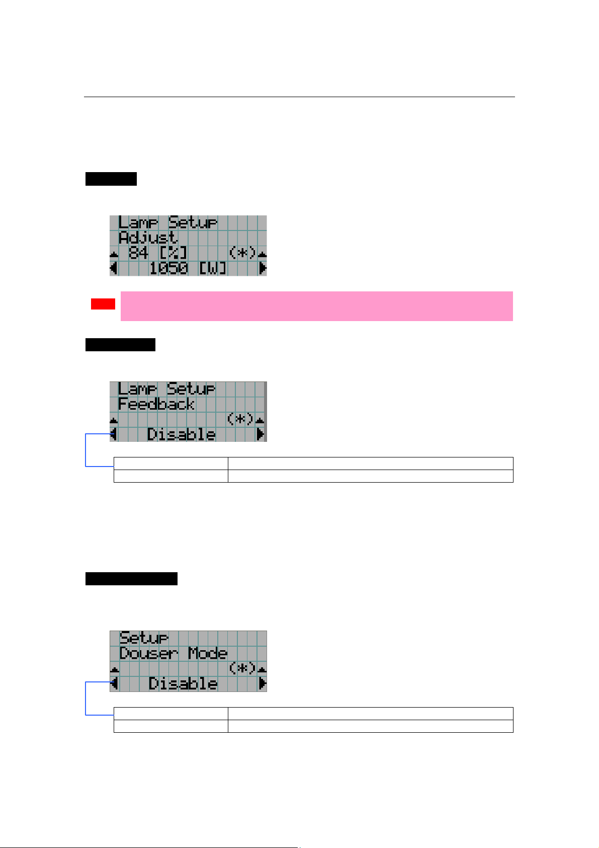
5.4.1 Lamp Setup
Adjust
Adjusts the lamp output (brightness). Control the output at “W” increments.
← Displays the lamp output (%) with regard to the setting.
← Adjusts the lamp brightness.
Note
• Lamp output below 70% will cause an error. Arrange the setting so that the lamp output
becomes 70% at least.
Feedback
Sets the lamp brightness constant mode that uses a brightness sensor.
← Displays the currently selected item with asterisk (*).
← Displays the setting.
Disable Disables the lamp brightness constant mode.
Enable Enables the lamp brightness constant mode.
5.4.2 Setup
This menu is for service personnel. For the procedure to use it, refer to “5.1. When you use
the service personnel menu” (page E-36).
Douser Mode
The douser function will be activated when signals are switched. Request your
dealer/distributor to perform the setting.
← Displays the currently selected item with asterisk (*).
← Displays the setting
Disable Disables the douser mode.
Enable Enables the douser mode.
NC800C 5. LCD Menu
E-40
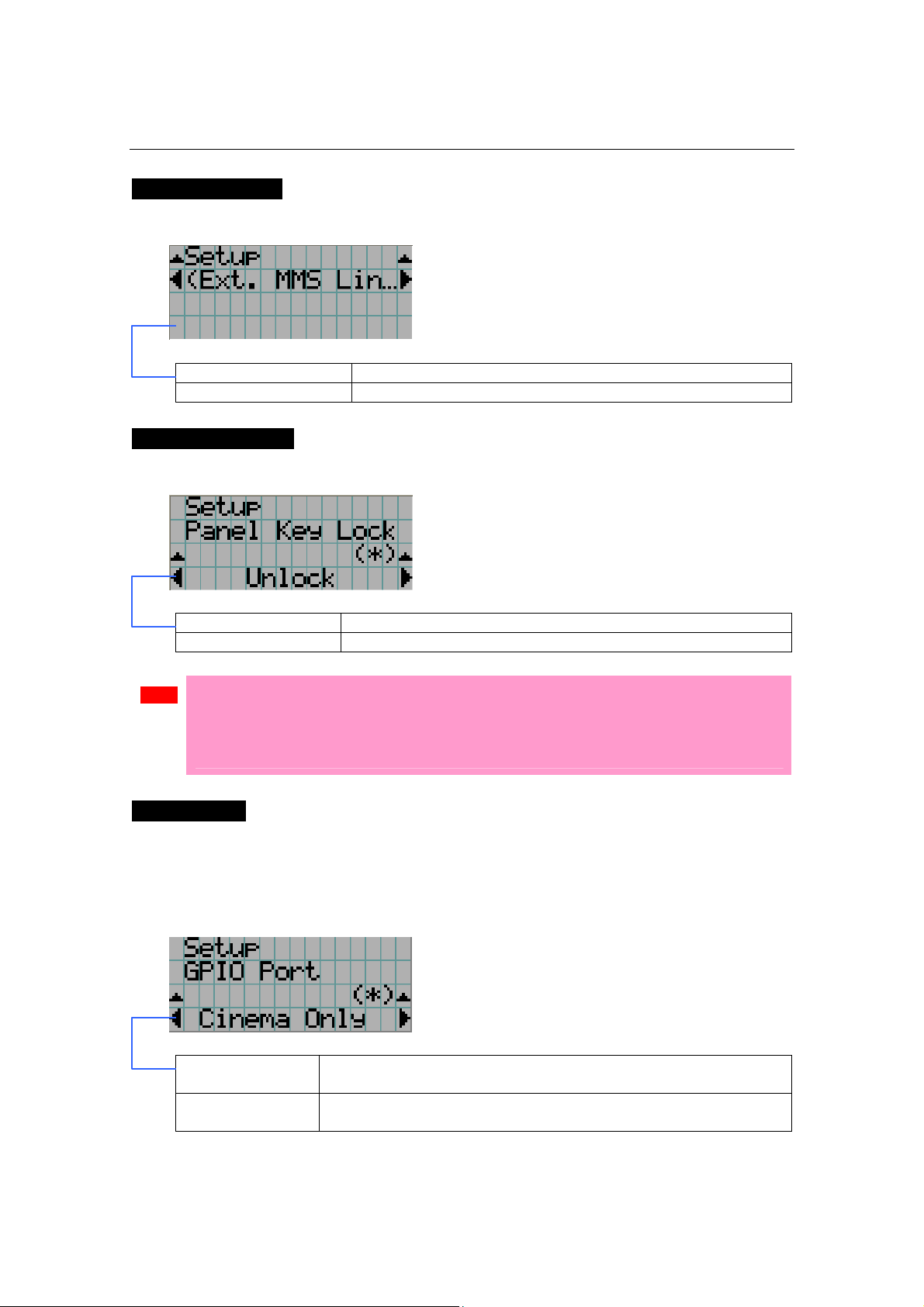
Ext. MMS Link
Connect an external multimedia switcher (MMS) to control the input signal.
← Displays the currently selected item with asterisk (*).
← Displays the setting
Connect To enable connection with external MMS
Disconnect To disable connection with external MMS
Panel Key Lock
The control buttons on your projector are locked to be inoperative.
← Displays the currently selected item with asterisk (*).
← Displays the setting
Lock Enable a lock on the control buttons on your projector.
Unlock Disable the lock on the control buttons.
Note
• Even if the buttons on the projector’s control panel are locked, remote controller buttons
are available.
• When the buttons on the projector’s control panel are locked, press the CANCEL button on
the projector for about 10 sec. to unlock them (The key lock setting on the projector
becomes Unlock).
GPIO Port
When controlling the projector from the external control terminal (GPI/O), select the subject
of GPI/O port control. With the control subject set to "Cinema Only", the projector does not
accept commands issued using the control panel buttons, remote controller or personal
computer.
← Displays the currently selected item with asterisk (*).
← Displays the setting
Cinema Only To restrict the subject of control from the external control terminal
(GPI/O) to the Cinema board only
System/Cinema To restrict the subject of control from the external control terminal
(GPI/O) to the System board and the Cinema board
NC800C 5. LCD Menu
E-41
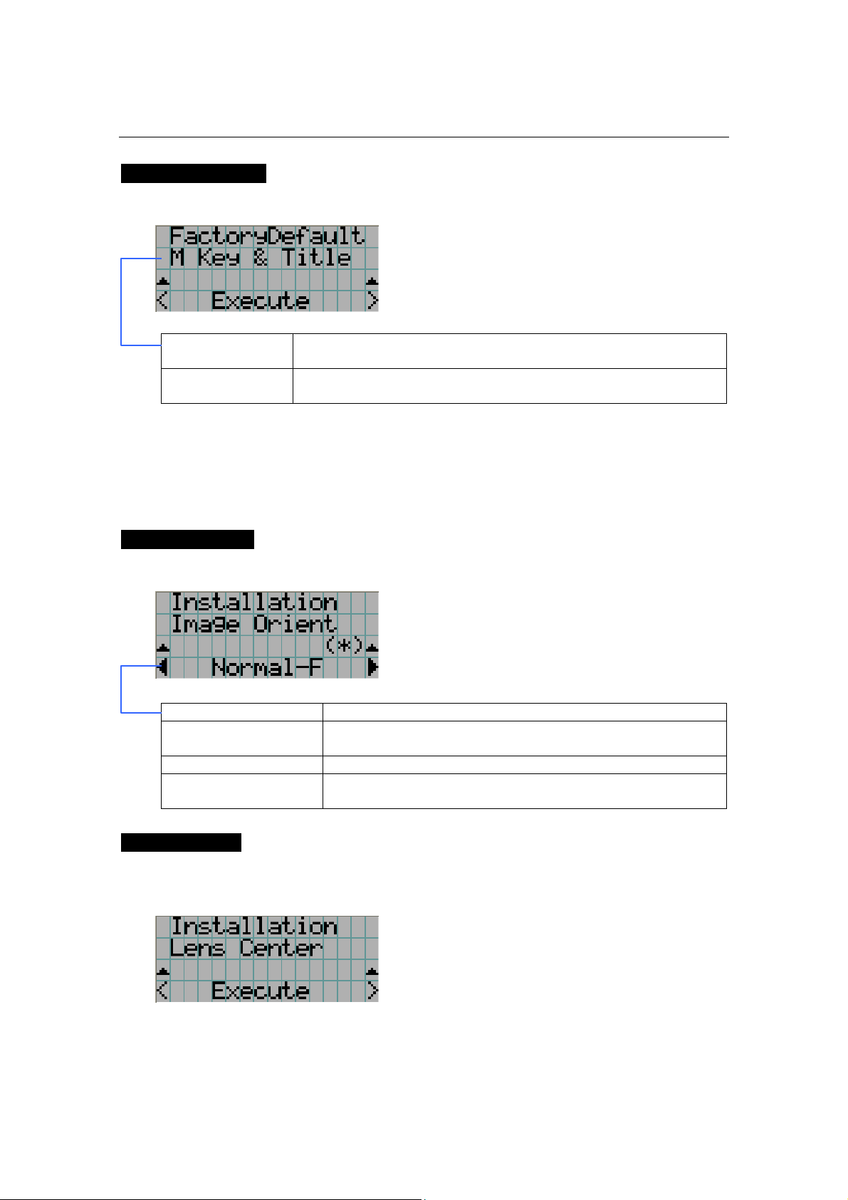
FactoryDefault
Used to select factory default values for the projector settings.
← Select the item to be reset.
← Press the ENTER button to execute resetting.
M Key & Title Titles are set to factory default ones. (Tiles you have created are
deleted, but files are not.)
All All the settings of your projector are set to factory default values except
for files.
5.4.3 Installation
This menu is the service personnel menu. For the using service personnel menu, refer to “5.1.
When you use the service personnel menu” (Page E-36).
Image Orient
Make a selection according to the setup position of your projector and screen.
← Displays the currently selected item with asterisk (*).
← Displays the setting
Normal-F Projection is made from front of the screen.
UpsideDown-R The projector body is installed upside down, and projection is
made from the back of the screen.
Normal-R Projection is made from behind the screen
UpsideDown-F The projector body is installed upside down, and projection is
made from the front of the screen.
Lens Center
To move the lens shift to the center position. The center position may slightly shift depending
upon mounting conditions of the lens.
← Press the ENTER button to execute moving.
NC800C 5. LCD Menu
E-42
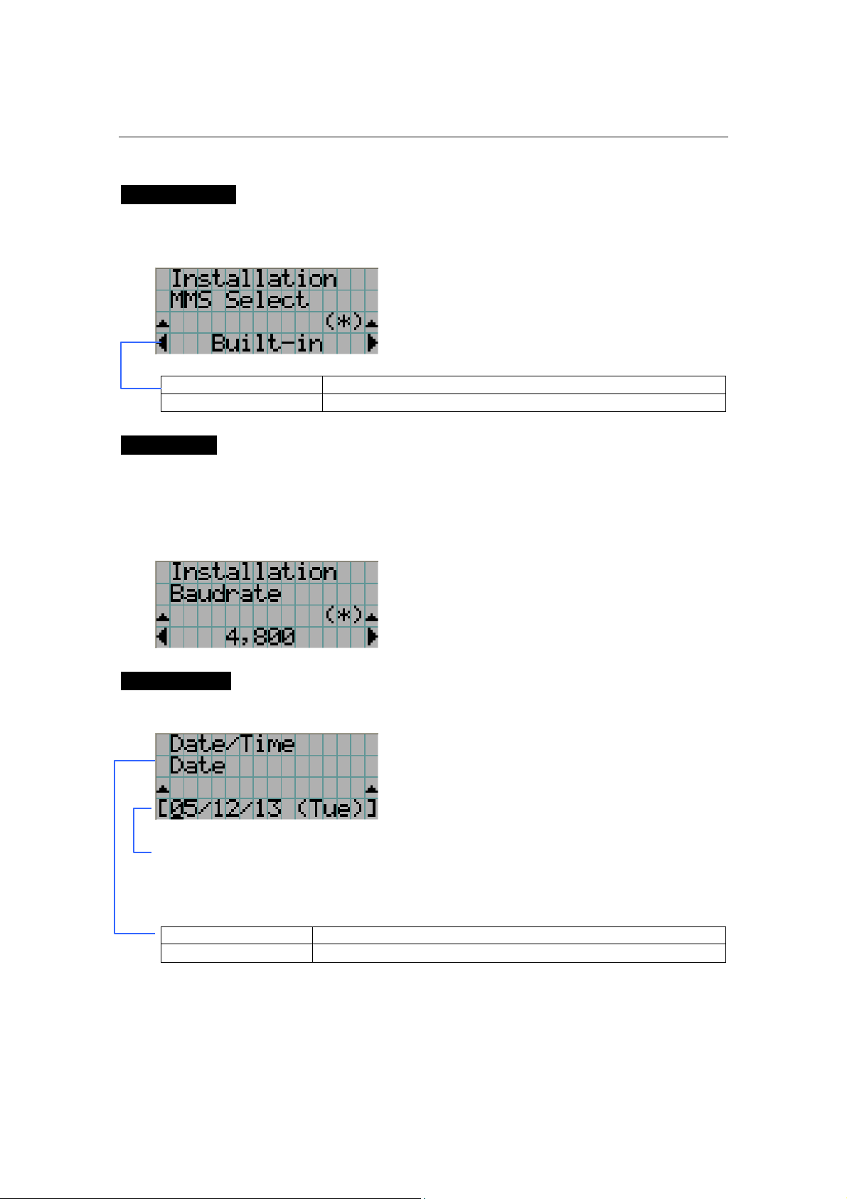
MMS Select
Select the MMS for operation when you use a multimedia switcher (MMS) separately sold.
You can connect only one MMS.
← Displays the currently selected item with asterisk (*).
← Displays the setting
External To use the externally connected MMS (optional)
Not Use Not to use MMS
Baudrate
To select the transmission speed (bps) for your projector (SYSTEM) and a PC when they are
connected by a commercially available RS-232C straight cable. Select one from 4800, 9600,
192000 and 38400. Select the transfer speed corresponding to the speed of the connected
devices.
← Displays the currently selected item with asterisk (*).
← Displays the setting
Date/Time
Use this to set the date and time on the projector.
← Select the item to be set
← Input numeric values
Use the remote controller to input numeric values. For the procedure to input
alphanumeric characters, refer to “Users Manual”.
Use the SELECT <Left/Right> buttons to move the cursor (under bar).
Date Set the date here (Year, month, day).
Time Set the time here (Hour, minute, second).
NC800C 5. LCD Menu
E-43
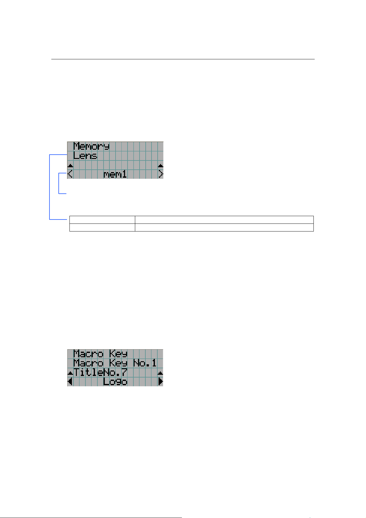
5.4.4 Memory
This menu is the service personnel menu. For the using service personnel menu, refer to “5.1.
When you use the service personnel menu” (Page E-36).
Save the current status of lamp and lens to the memory in the projector (lens memory
function and lamp memory function).
The saved contents are assigned to the titles for use.
← Select the saving item
← Display the registered memory name
Press the ENTER button to display the confirmation message asking you whether this
memory can be overwritten or not.
Lamp To save the current lamp status
Lens To save the current lens status
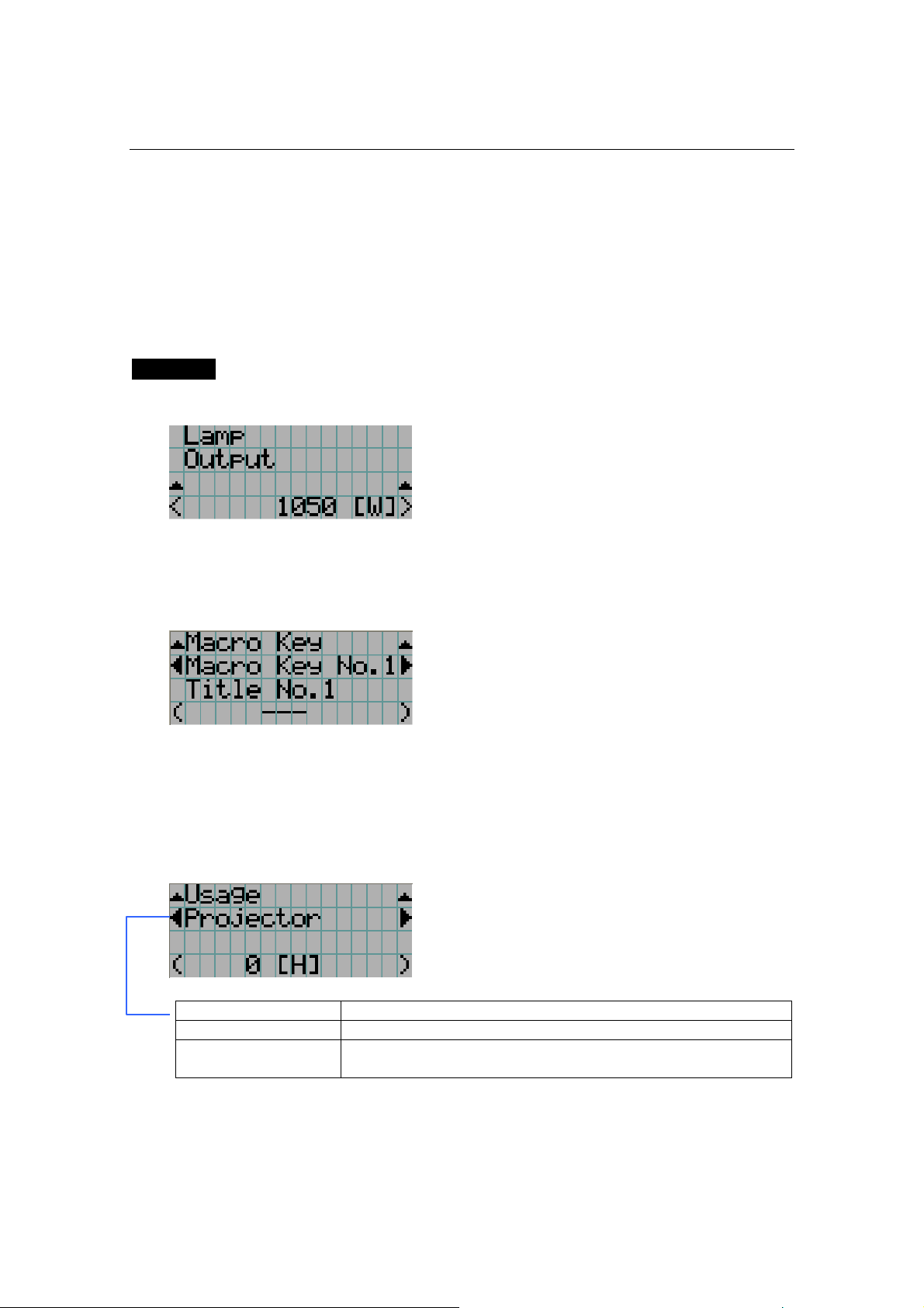
5.5 Title Setup
This menu is the service personnel menu. For the using service personnel menu, refer to“5.1.
When you use the service personnel menu” (Page E-36).
5.5.1 Macro Key
Use this key to set the titles to be assigned to the macro keys.
You cannot assign the same title to several macro keys. If you want to assign any title to
another number, cancel the assignment once and then set it to any key again.
← Select the macro key number (1 to 8)
← Display the selected number of the title
← Select the titles to be assigned to the macro keys
Select the titles from those registered in advance.
To clear assignment to macro keys, select “---“.
NC800C 5. LCD Menu
E-44
5.6 Information
Displays the hours of lamp bulb use, the version information and error codes.
5.6.1 Lamp
Displays information relating to the lamp. (Such as lamp output and the type of lamp bulb.)
Output
Displays the lamp brightness (output) setting.
← Displays the power consumption (W).
5.6.2 Macro Key
Displays the titles assigned to the macro keys of 1 to 8 on the projector’s control panel.
← Selects the macro key whose contents you want to display.
← Displays the assigned title numbers.
← Displays the registered names of the assigned titles.
5.6.3 Usage
Displays the hours of projector head, lamp, and lamp house usage, and warning display time
of the lamp bulb.
← Selects the item to display.
← Displays the hours of use (H).
Projector Displays the hours of projector head use.
Bulb Displays the hours of use of the current lamp bulb.
Remaining Time Remaining Time: This shows the remaining lamp utilization time (for
reference).
NC800C 5. LCD Menu
E-45
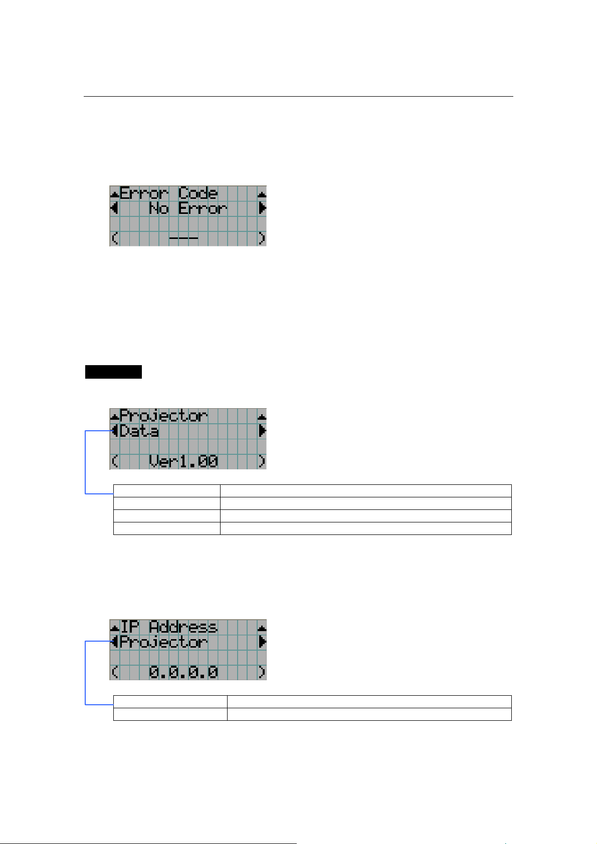
5.6.4 Error Code
Displays the error code when an error occurs. See the “Error Code List” in the Appendix for
details on error codes.
← Displays the code of the error currently occurring.
← Displays the name of the error currently occurring.
When multiple errors occur, you can display them by pressing the [MENU CTL]
LEFT/RIGHT buttons.
5.6.5 Version
Displays the versions of the projector head, and the multi-media switcher (MMS) (optional).
System
Displays the version information of the projector head.
← Selects the item to display.
← Displays the version information.
BIOS Displays the BIOS version of the projector head.
Firmware Displays the firmware version of the projector head.
Data Displays the data version of the projector head.
Serial No. Displays the serial number of the projector head.
5.6.6 IP Address
Displays the IP address set in the projector head.
← Selects the item to display the IP address.
← Displays the IP address.
System Displays the IP address set for the projector head (System).
Cinema Displays the IP address set for the projector head (Cinema).
NC800C 5. LCD Menu
E-46
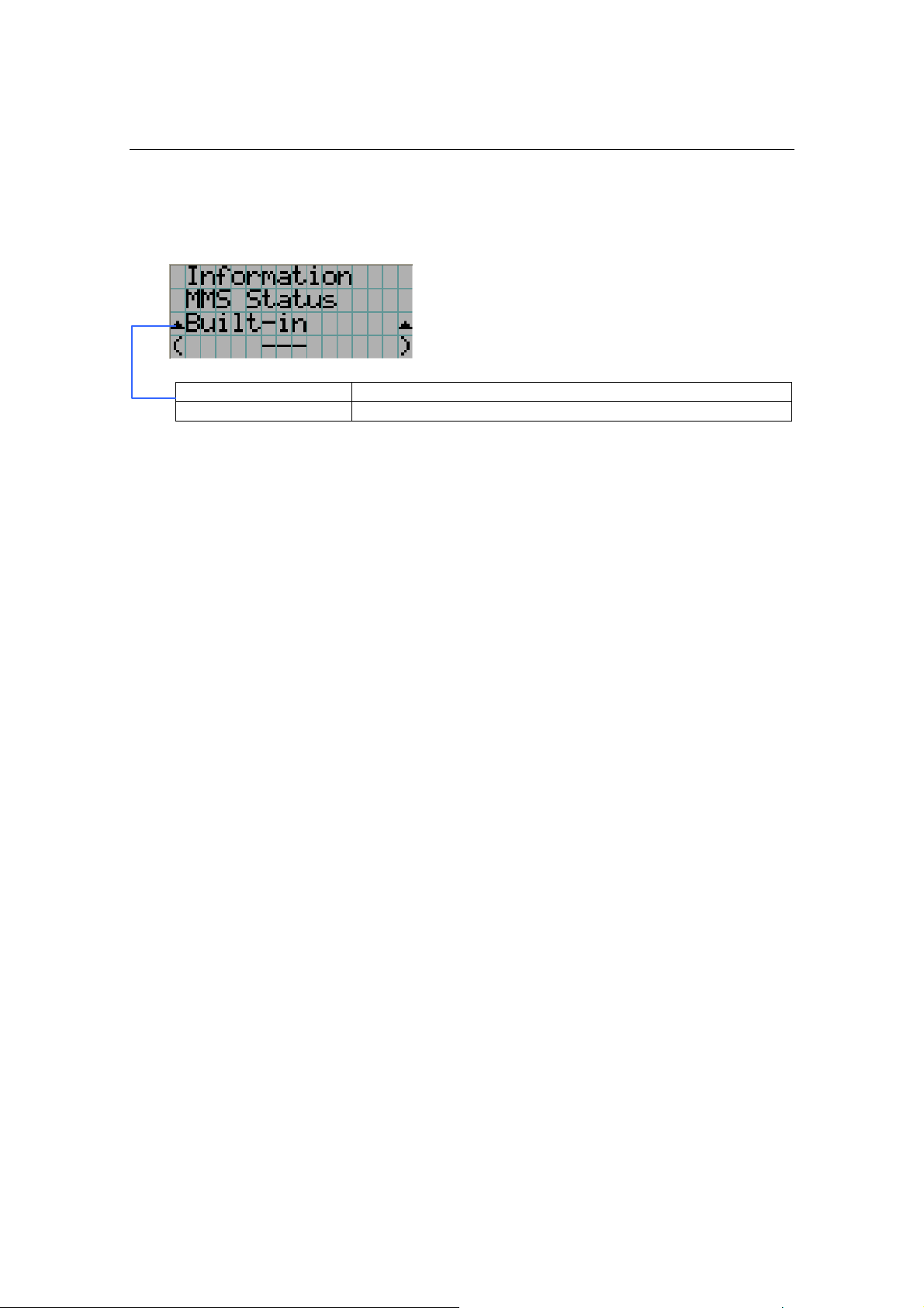
5.6.7 MMS Status
Indicates the status of the multi-media switcher (MMS) connected to your projector.
← Displays the status information of MMS linked operations.
← Displays the IP address of MMS.
External External multi-media switcher (MMS) is linked.
Not Use There is no link established.

E-47
6.
Appendix
6.1 List of registered titles (when shipped from the
factory)
The data listed below have been cataloged in your projector before shipping from our factory.
When projecting an image source covered by these data, you do not need to change the
settings of your projector.
List of default Titles
FILES source Macro
Key No.
TITLE Input
PCF SCREEN active aspect
TCGD Anamorphic
Lens
1 CS-SCOPE
1920
SDI-A CS-SCOPE
1920x1080
Anamo1.25
SCOPE
1920x1080 2.35 P7v2
theatre
1.25
2 VV-FLAT
1920
SDI-B VV-FLAT
1920x1080
DC2K VISTA 1920x1080 1.85 P7v2
theatre
none
3 HDTV SDI-A HDTV
1920x1080
DC2K HDTV 1920x1080 0 Rec 709 none
4 SDI-DUAL-
RGB
SDI-A,B SDI DUAL RGB
1920x1080
2048x1080
No Crop
1920x1080 0 P7v2
theatre
none
5 DVI-A DVI-A DVI
2048x1080
DC2K DVI 2048x1080 0 P7v2
theatre
none
6 DVI-B DVI-B DVI
2048x1080
DC2K DVI 2048x1080 0 P7v2
theatre
none
7 DVI-TWIN DVI-A,B DVI
2048x1080
DC2K DVI 2048x1080 0 P7v2
theatre
none

NC800C 6. Appendix
E-48
6.2 Index
A
Adjust ................................................... E-39
B
Baudrate ............................................... E-42
Bulb Alignment....................................... E-37
C
Configuration ......................................... E-39
D
Date/Time .............................................E-42
Dowser Mode ......................................... E-39
E
Error Code ............................................. E-45
Ext. MMS Link ........................................ E-40
F
FactoryDefault........................................ E-41
Feedback ............................................... E-39
G
GPIO Port .............................................. E-40
H
Horizontal moving screen mask ..................E-9
How to Calculate the Magnification of Primary
Lens ..................................................E-11
I
Image Orient ......................................... E-41
Information............................................ E-44
Installation ............................................ E-41
IP Address ............................................. E-45
L
Lamp .................................................... E-44
Lamp Setup ........................................... E-39
Lens Center ........................................... E-41
List of default Titles ................................ E-47
M
Macro Key ....................................... E-43, 44
Memory................................................. E-43
MMS Select ............................................ E-42
MMS Status ........................................... E-46
O
Option lenses ......................................... E-10
Output .................................................. E-44
P
Panel Key Lock ....................................... E-40
Projected Images ................................... E-10
S
Setup.................................................... E-39
System.................................................. E-45
T
Test Pattern ........................................... E-38
Title Memory.......................................... E-38
Title Select ............................................ E-38
Title Setup ............................................. E-43
U
Usage ................................................... E-44
V
Version.................................................. E-45
Vertical moving screen mask......................E-9

© NEC Viewtechnology, Ltd. 2006-2007
Ver.2.00. 01/07