
OWNERS GUIDE
MARVEL PROFESSIONAL UNDERCOUNTER REFRIGERATION
THE ORIGINAL REFRIGERATION EXPERTS SINCE 1892
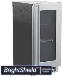
FOR MODEL # MPBV415
OWNER’S GUIDE
MARVEL PROFESSIONAL UNDERCOUNTER REFRIGERATION
THE ORIGINAL REFRIGERATION EXPERTS SINCE 1892
FOR MODEL # MPCP415
WELCOME
Welcome to the Marvel Experience
Congratulations on your purchase of the industry’s quietest
clear ice machine with the best ice clarity and purity. Your
new investment is protected by a limited warranty for the
rst year, and hermetically sealed refrigeration system parts
are covered for an additional 4 years.
Here’s your guide to the operation and maintenance of your
Marvel Clear Ice Machine to ensure years of enjoyment. If
you have any questions, please contact Marvel Customer
Service or Tech Support at:
Phone: (616) 754-5601
Email:
Got a Marvelous Design?
We would love to see how your Marvel product looks in its
new home. Send us photos at marketing@marvelrefriger-
ation.com, and we might feature your Marvel home design
on our website and social media!
Bonus Third-Year Warranty Free with Product
Registration
Your Marvel Professional product
qualies for a one-year extension
of the two-year warranty coverage
from your date of purchase, free
of charge. To take advantage of
this third-year warranty, be sure to
register your product with Marvel
within 60 days from the date of pur-
chase at marvelrefrigeration.com
and provide proof of purchase.
Thank you again for investing in Marvel for your home!
Warranty Registration
It is important you send in your warranty registration card
immediately after taking delivery of your appliance or you
can register online at www.marvelrefrigeration.com.
The following information will be
required when registering your
appliance:
Service Number
Serial Number
Date of Purchase
Dealer’s name and address
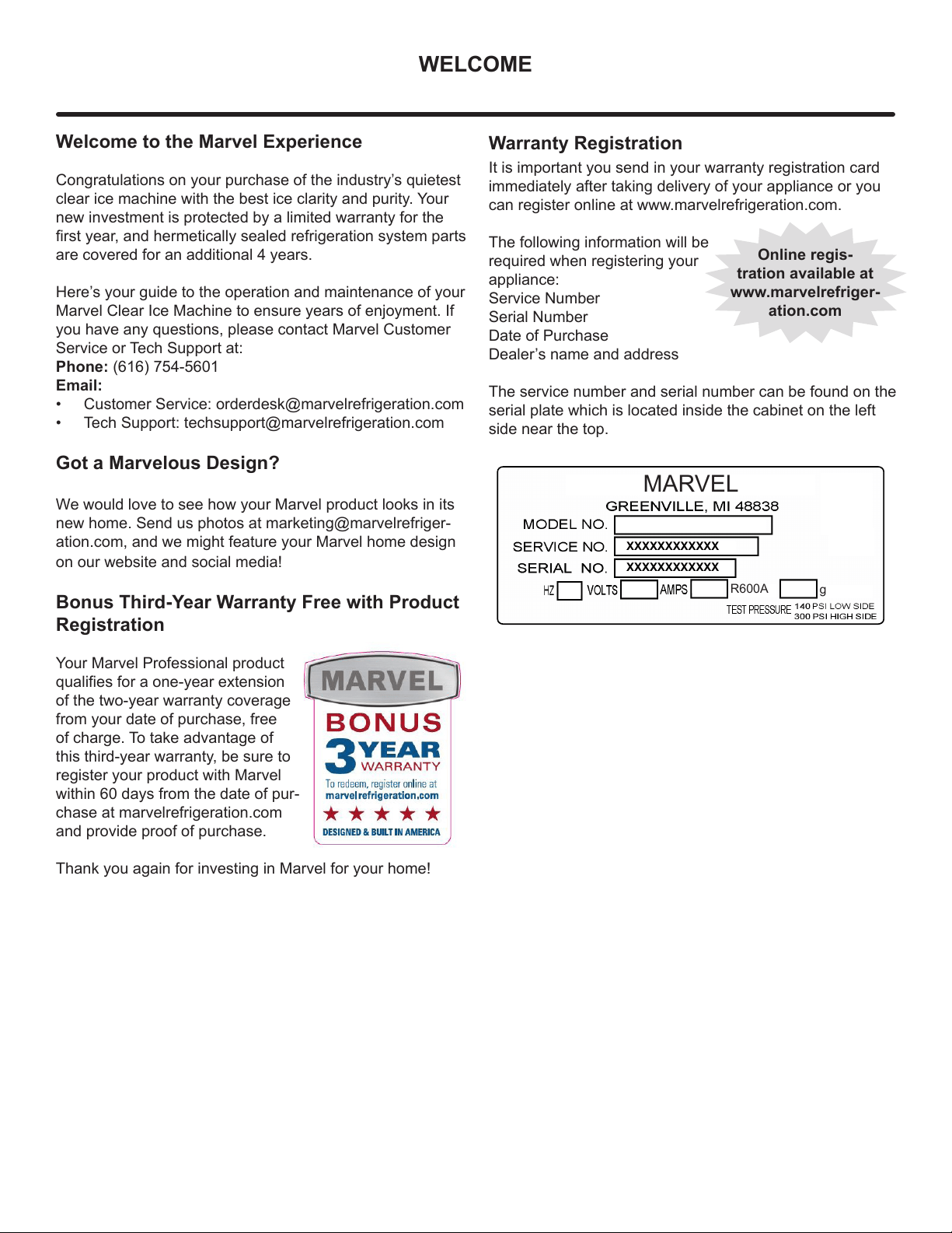
The service number and serial number can be found on the
serial plate which is located inside the cabinet on the left
side near the top.
Online regis-
tration available at
www.marvelrefriger-
ation.com
XXXXXXXXXXXX
XXXXXXXXXXXX
MARVEL
g
R600A

TABLE OF CONTENTS
Tip: Click on any section below to jump directly there
Safety
Important Safety Instructions
Installation
Unpacking Your Appliance
Electrical
Cutout & Product Dimensions
Installing Your Appliance
Side-by-Side & Stacking Installations
Door Reversal
Integrated Panel Dimensions
Integrated Panel Installation
Installing The Water Supply
Installing the Drain plumbing
Maintenance
Care and Cleaning
Long-Term Storage/Winterization
Operating Instructions
Using Your Electronic Control
Service
Obtaining Service
Troubleshooting
Product Liability
Warranty Claims
Ordering Replacement Parts
R600a Specifications
System Diagnosis Guide
Compressor Specifications
Control Operation - Service
Thermistor
Warranty
3
NOTE
!
CAUTION
Important Safety Instructions
Warnings and safety instructions appearing in this guide
are not meant to cover all possible conditions and situa-
tions that may occur. Common sense, caution, and care
must be exercised when installing, maintaining, or operat-
ing this appliance.
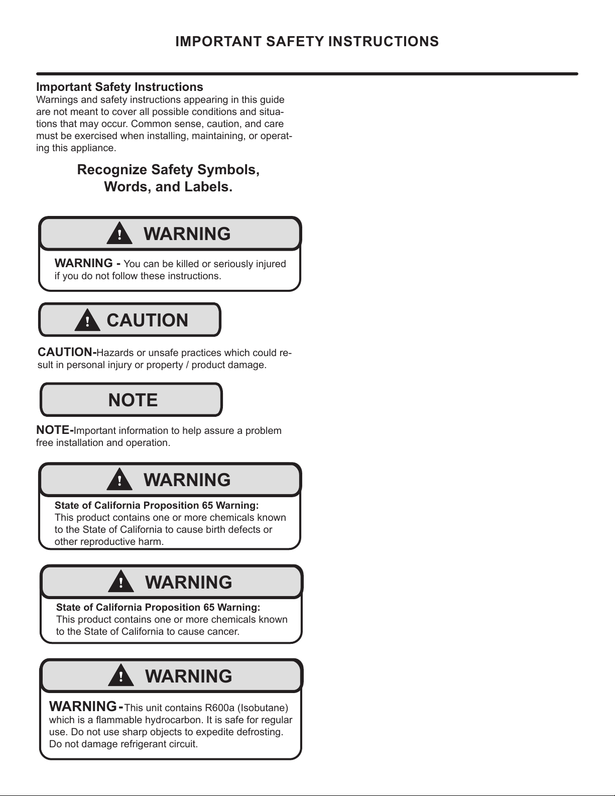
Recognize Safety Symbols,
Words, and Labels.
CAUTION-Hazards or unsafe practices which could re-
sult in personal injury or property / product damage.
NOTE-Important information to help assure a problem
free installation and operation.
IMPORTANT SAFETY INSTRUCTIONS
!
WARNING
WARNING - You can be killed or seriously injured
if you do not follow these instructions.
!
WARNING
State of California Proposition 65 Warning:
This product contains one or more chemicals known
to the State of California to cause cancer.
!
WARNING
State of California Proposition 65 Warning:
This product contains one or more chemicals known
to the State of California to cause birth defects or
other reproductive harm.
!
WARNING
WARNING - This unit contains R600a (Isobutane)
which is a ammable hydrocarbon. It is safe for regular
use. Do not use sharp objects to expedite defrosting.
Do not damage refrigerant circuit.
4
NOTE
!
WARNING
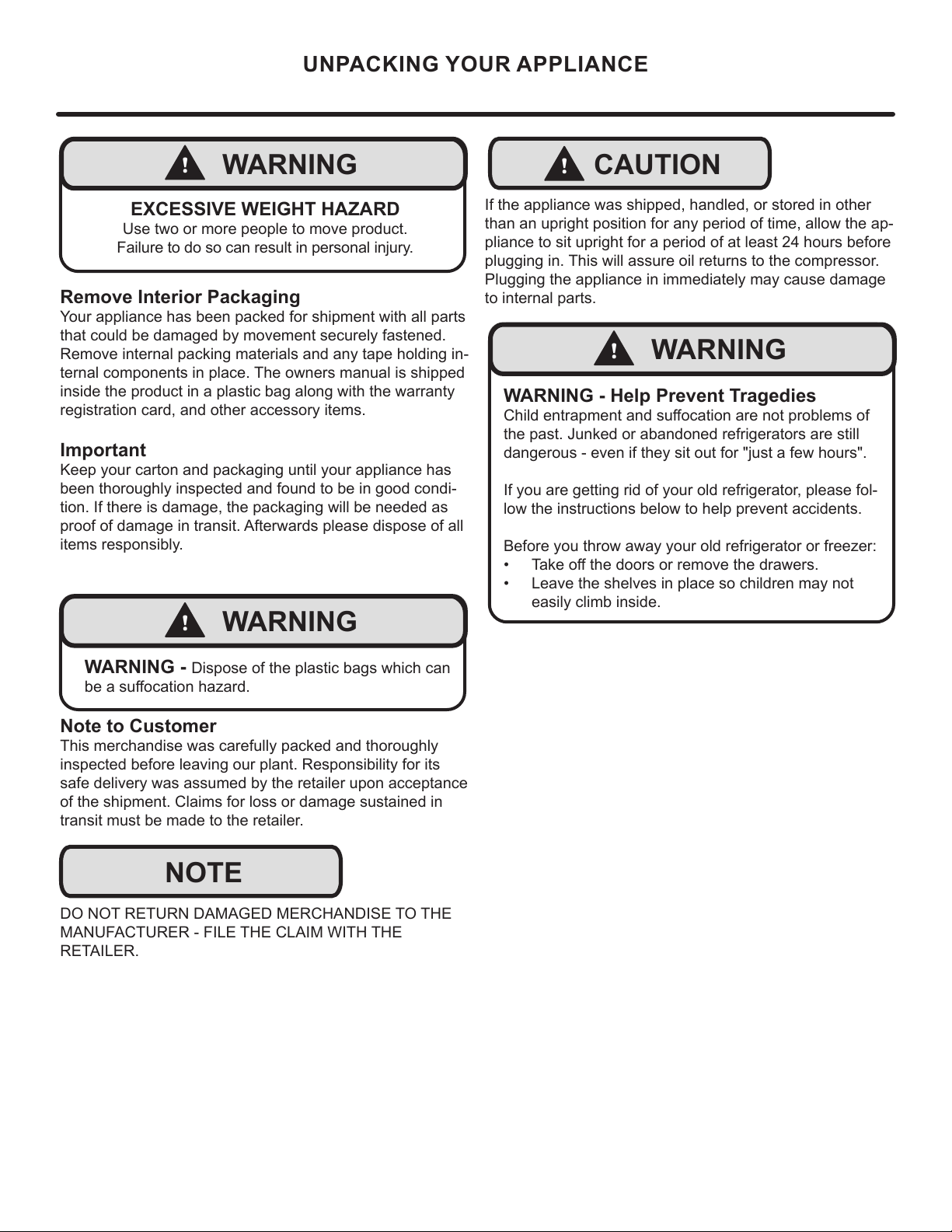
WARNING - Dispose of the plastic bags which can
be a suocation hazard.
UNPACKING YOUR APPLIANCE
!
CAUTION
!
WARNING
WARNING - Help Prevent Tragedies
Child entrapment and suocation are not problems of
the past. Junked or abandoned refrigerators are still
dangerous - even if they sit out for "just a few hours".
If you are getting rid of your old refrigerator, please fol-
low the instructions below to help prevent accidents.
Before you throw away your old refrigerator or freezer:
• Take o the doors or remove the drawers.
• Leave the shelves in place so children may not
easily climb inside.
!
WARNING
EXCESSIVE WEIGHT HAZARD
Use two or more people to move product.
Failure to do so can result in personal injury.
Remove Interior Packaging
Your appliance has been packed for shipment with all parts
that could be damaged by movement securely fastened.
Remove internal packing materials and any tape holding in-
ternal components in place. The owners manual is shipped
inside the product in a plastic bag along with the warranty
registration card, and other accessory items.
Important
Keep your carton and packaging until your appliance has
been thoroughly inspected and found to be in good condi-
tion. If there is damage, the packaging will be needed as
proof of damage in transit. Afterwards please dispose of all
items responsibly.
Note to Customer
This merchandise was carefully packed and thoroughly
inspected before leaving our plant. Responsibility for its
safe delivery was assumed by the retailer upon acceptance
of the shipment. Claims for loss or damage sustained in
transit must be made to the retailer.
DO NOT RETURN DAMAGED MERCHANDISE TO THE
MANUFACTURER - FILE THE CLAIM WITH THE
RETAILER.
If the appliance was shipped, handled, or stored in other
than an upright position for any period of time, allow the ap-
pliance to sit upright for a period of at least 24 hours before
plugging in. This will assure oil returns to the compressor.
Plugging the appliance in immediately may cause damage
to internal parts.
5
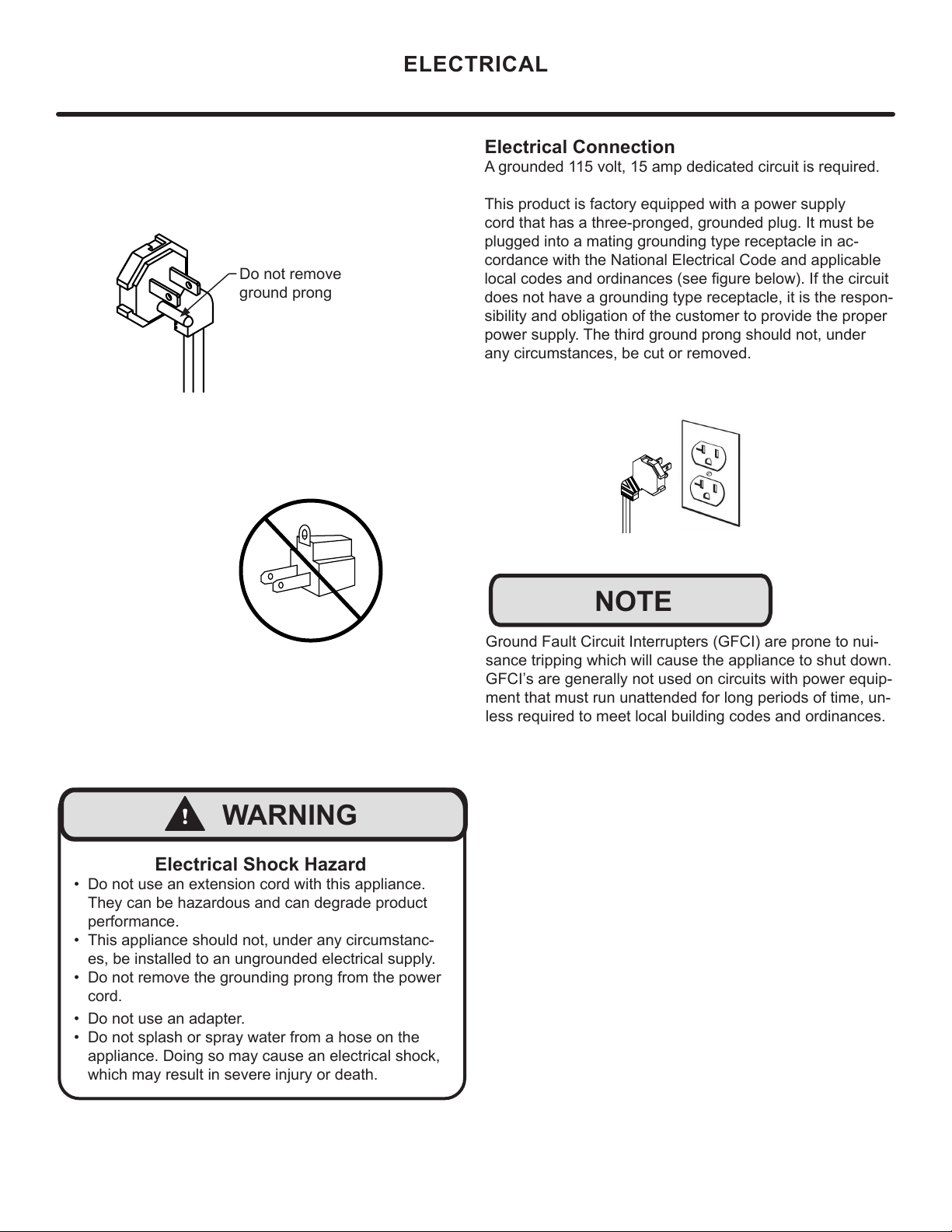
Electrical Connection
A grounded 115 volt, 15 amp dedicated circuit is required.
This product is factory equipped with a power supply
cord that has a three-pronged, grounded plug. It must be
plugged into a mating grounding type receptacle in ac-
cordance with the National Electrical Code and applicable
local codes and ordinances (see gure below). If the circuit
does not have a grounding type receptacle, it is the respon-
sibility and obligation of the customer to provide the proper
power supply. The third ground prong should not, under
any circumstances, be cut or removed.
NOTE
Ground Fault Circuit Interrupters (GFCI) are prone to nui-
sance tripping which will cause the appliance to shut down.
GFCI’s are generally not used on circuits with power equip-
ment that must run unattended for long periods of time, un-
less required to meet local building codes and ordinances.
ELECTRICAL
Do not remove
ground prong
Electrical Shock Hazard
• Do not use an extension cord with this appliance.
They can be hazardous and can degrade product
performance.
• This appliance should not, under any circumstanc-
es, be installed to an ungrounded electrical supply.
• Do not remove the grounding prong from the power
cord.
• Do not use an adapter.
• Do not splash or spray water from a hose on the
appliance. Doing so may cause an electrical shock,
which may result in severe injury or death.
!
WARNING
6
"C"
CUTOUT AND PRODUCT DIMENSIONS
"A"
"B"
"D"
"E"
Solid door
shown
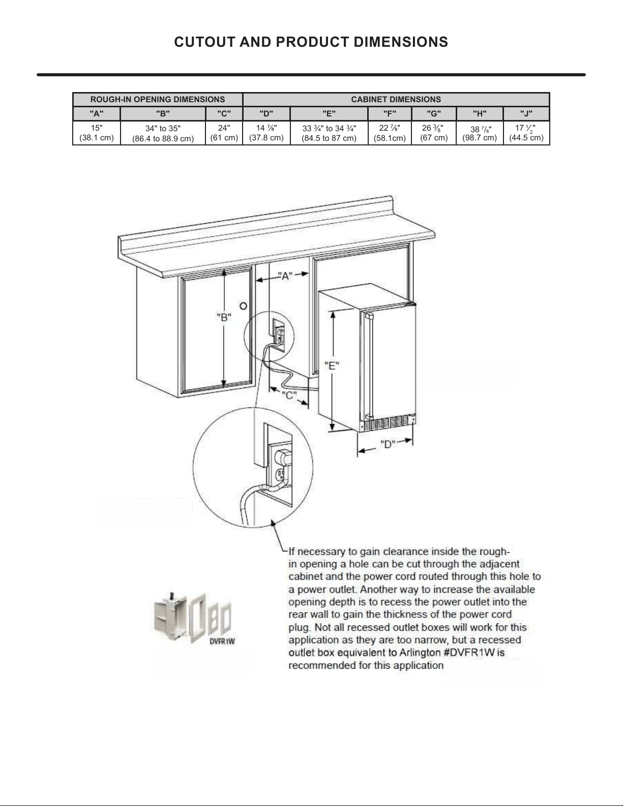
If necessary, to gain clearance inside the rough-in
opening, a hole can be cut through the adjacent
cabinet and the power cord routed through this hole to
a power outlet. Another way to increase the available
opening depth is to recess the power outlet into the
rear wall to gain the thickness of the power cord plug.
Not all recessed outlet boxes will work for this applica-
tion as they are too narrow, but a recessed outlet box
equivalent to Arlington #DVFR1W is recommended for
ROUGH-IN OPENING DIMENSIONS CABINET DIMENSIONS
"A" "B" "C" "D" "E" "F" "G" "H" "J"
15"
24"
34" to 35"
(
8
7
General Installation
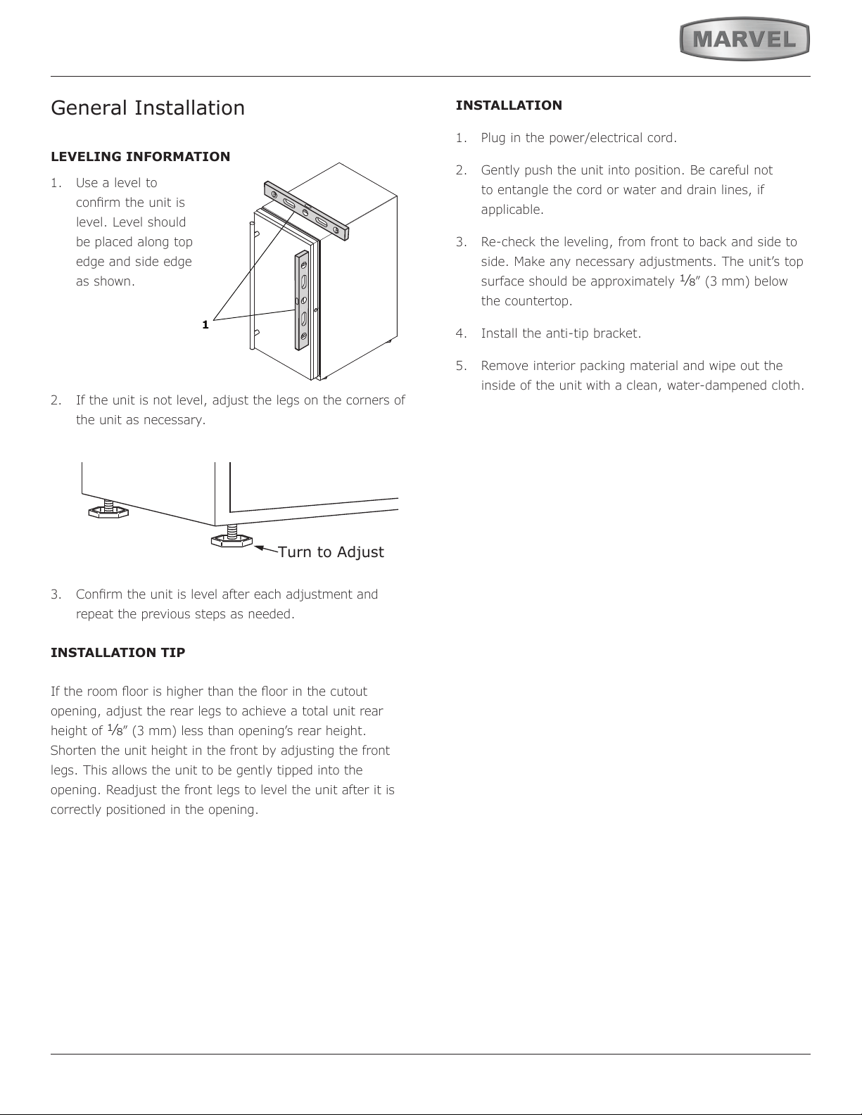
LEVELING INFORMATION
1. Use a level to
conrm the unit is
level. Level should
be placed along top
edge and side edge
as shown.
2. If the unit is not level, adjust the legs on the corners of
the unit as necessary.
3. Conrm the unit is level after each adjustment and
repeat the previous steps as needed.
INSTALLATION TIP
If the room oor is higher than the oor in the cutout
opening, adjust the rear legs to achieve a total unit rear
height of
1⁄8” (3 mm) less than opening’s rear height.
Shorten the unit height in the front by adjusting the front
legs. This allows the unit to be gently tipped into the
opening. Readjust the front legs to level the unit after it is
correctly positioned in the opening.
INSTALLATION
1. Plug in the power/electrical cord.
2. Gently push the unit into position. Be careful not
to entangle the cord or water and drain lines, if
applicable.
3. Re-check the leveling, from front to back and side to
side. Make any necessary adjustments. The unit’s top
surface should be approximately
1⁄8” (3 mm) below
the countertop.
4. Install the anti-tip bracket.
5. Remove interior packing material and wipe out the
inside of the unit with a clean, water-dampened cloth.
1
Turn to Adjust
8
SIDE-BY-SIDE AND STACKING INSTALLATIONS
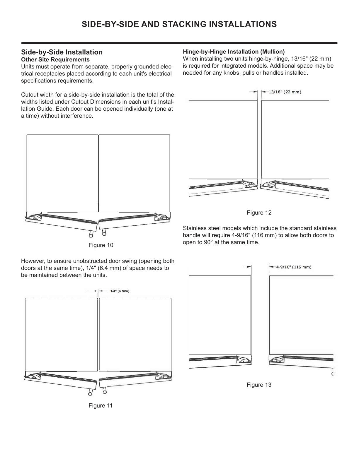
Side-by-Side Installation
Other Site Requirements
Units must operate from separate, properly grounded elec-
trical receptacles placed according to each unit's electrical
specications requirements.
Cutout width for a side-by-side installation is the total of the
widths listed under Cutout Dimensions in each unit's Instal-
lation Guide. Each door can be opened individually (one at
a time) without interference.
Figure 10
However, to ensure unobstructed door swing (opening both
doors at the same time), 1/4" (6.4 mm) of space needs to
be maintained between the units.
Hinge-by-Hinge Installation (Mullion)
When installing two units hinge-by-hinge, 13/16" (22 mm)
is required for integrated models. Additional space may be
needed for any knobs, pulls or handles installed.
Stainless steel models which include the standard stainless
handle will require 4-9/16" (116 mm) to allow both doors to
open to 90° at the same time.
Figure 11
Figure 12
Figure 13
9
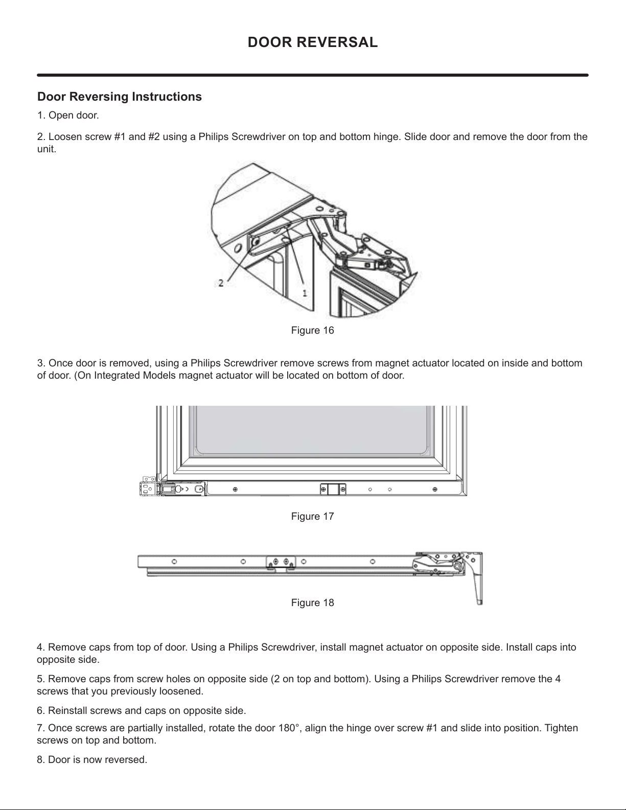
Door Reversing Instructions
1. Open door.
2. Loosen screw #1 and #2 using a Philips Screwdriver on top and bottom hinge. Slide door and remove the door from the
unit.
3. Once door is removed, using a Philips Screwdriver remove screws from magnet actuator located on inside and bottom
of door. (On Integrated Models magnet actuator will be located on bottom of door.
Figure 16
Figure 17
Figure 18
4. Remove caps from top of door. Using a Philips Screwdriver, install magnet actuator on opposite side. Install caps into
opposite side.
5. Remove caps from screw holes on opposite side (2 on top and bottom). Using a Philips Screwdriver remove the 4
screws that you previously loosened.
6. Reinstall screws and caps on opposite side.
7. Once screws are partially installed, rotate the door 180°, align the hinge over screw #1 and slide into position. Tighten
screws on top and bottom.
8. Door is now reversed.
DOOR REVERSAL
10
1
5
⁄32"
(2.9 cm)
Hinge side of door
Top of door
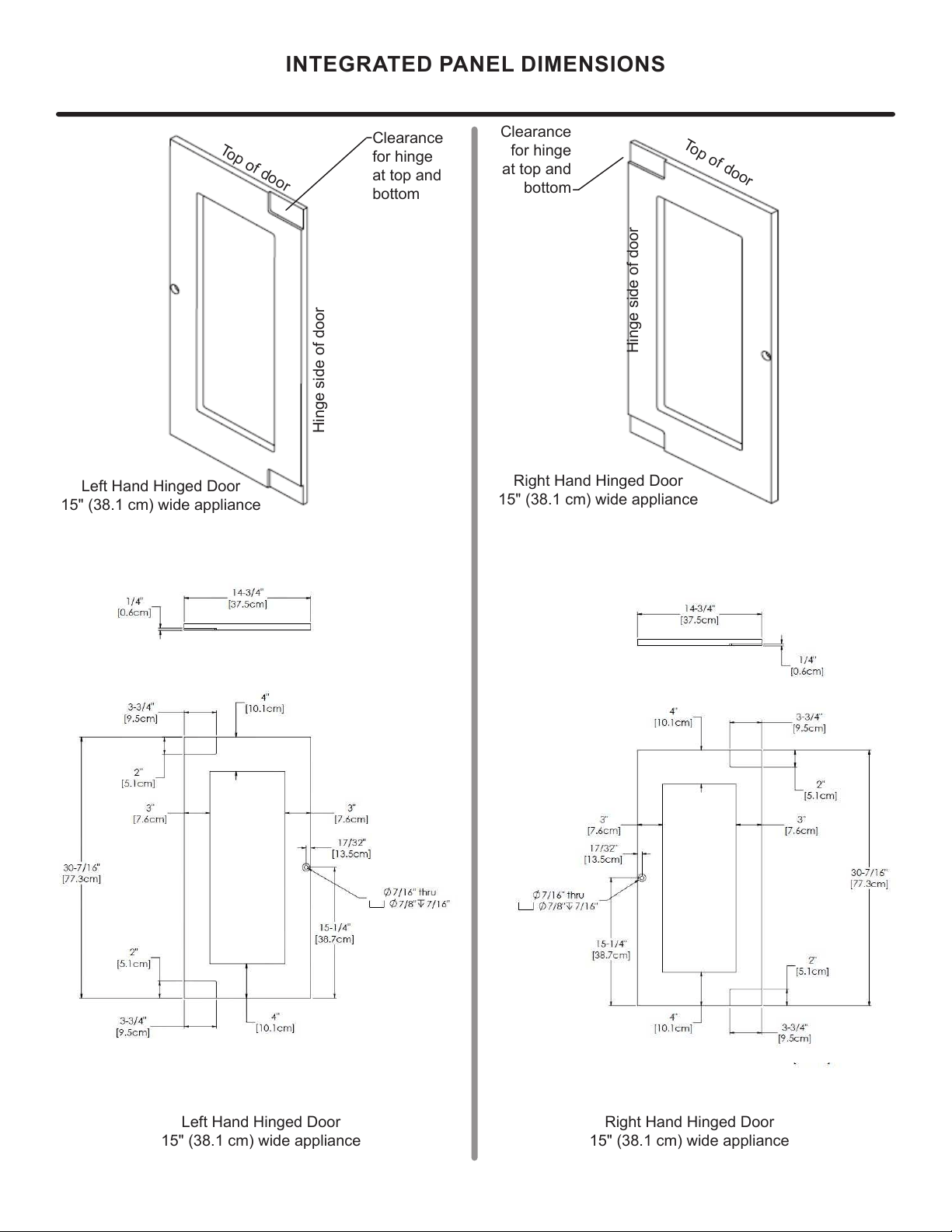
INTEGRATED PANEL DIMENSIONS
Right Hand Hinged Door
15" (38.1 cm) wide appliance
Right Hand Hinged Door
15" (38.1 cm) wide appliance
Clearance
for hinge
at top and
bottom
Hinge side of door
Top of door
Left Hand Hinged Door
15" (38.1 cm) wide appliance
Left Hand Hinged Door
15" (38.1 cm) wide appliance
Clearance
for hinge
at top and
bottom
11
INTEGRATED DOOR PANEL INSTALLATION
!
CAUTION
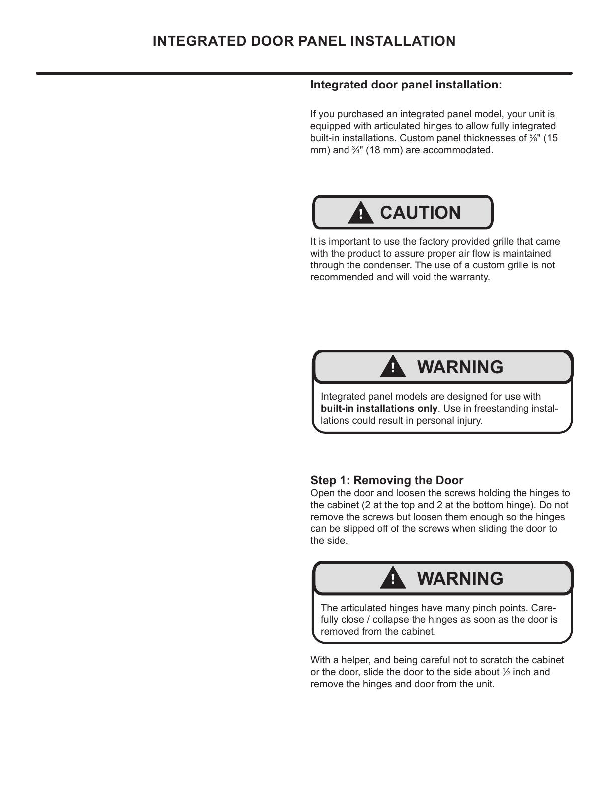
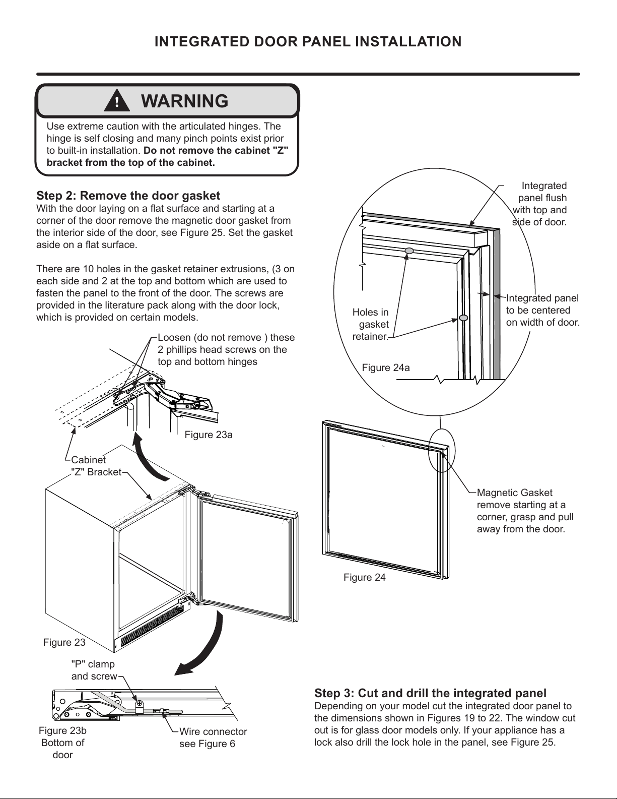
Integrated door panel installation:
Step 1: Removing the Door
Open the door and loosen the screws holding the hinges to
the cabinet (2 at the top and 2 at the bottom hinge). Do not
remove the screws but loosen them enough so the hinges
the side.
With a helper, and being careful not to scratch the cabinet
or the door, slide the door to the side about
1
2 inch and
remove the hinges and door from the unit.
!
WARNING
Integrated panel models are designed for use with
built-in installations only. Use in freestanding instal-
lations could result in personal injury.
If you purchased an integrated panel model, your unit is
equipped with articulated hinges to allow fully integrated
built-in installations. Custom panel thicknesses of
5
8" (15
mm) and
3
4" (18 mm) are accommodated.
It is important to use the factory provided grille that came
through the condenser. The use of a custom grille is not
recommended and will void the warranty.
!
WARNING
The articulated hinges have many pinch points. Care-
fully close / collapse the hinges as soon as the door is
removed from the cabinet.
12
INTEGRATED DOOR PANEL INSTALLATION
Integrated
with top and
side of door.
Magnetic Gasket
remove starting at a
corner, grasp and pull
away from the door.
Step 3: Cut and drill the integrated panel
Depending on your model cut the integrated door panel to
the dimensions shown in Figures 19 to 22. The window cut
out is for glass door models only. If your appliance has a
lock also drill the lock hole in the panel, see Figure 25.
Integrated panel
to be centered
on width of door.
Figure 24
Holes in
gasket
retainer.
Figure 24a
Step 2: Remove the door gasket
corner of the door remove the magnetic door gasket from
the interior side of the door, see Figure 25. Set the gasket
each side and 2 at the top and bottom which are used to
fasten the panel to the front of the door. The screws are
provided in the literature pack along with the door lock,
which is provided on certain models.
Loosen (do not remove ) these
2 phillips head screws on the
top and bottom hinges
!
WARNING
to built-in installation. Do not remove the cabinet "Z"
bracket from the top of the cabinet.
Figure 23b
Bottom of
door
"P" clamp
and screw
Wire connector
see Figure 6
Figure 23
Figure 23a
Cabinet
"Z" Bracket
13
!
CAUTION
INTEGRATED DOOR PANEL INSTALLATION
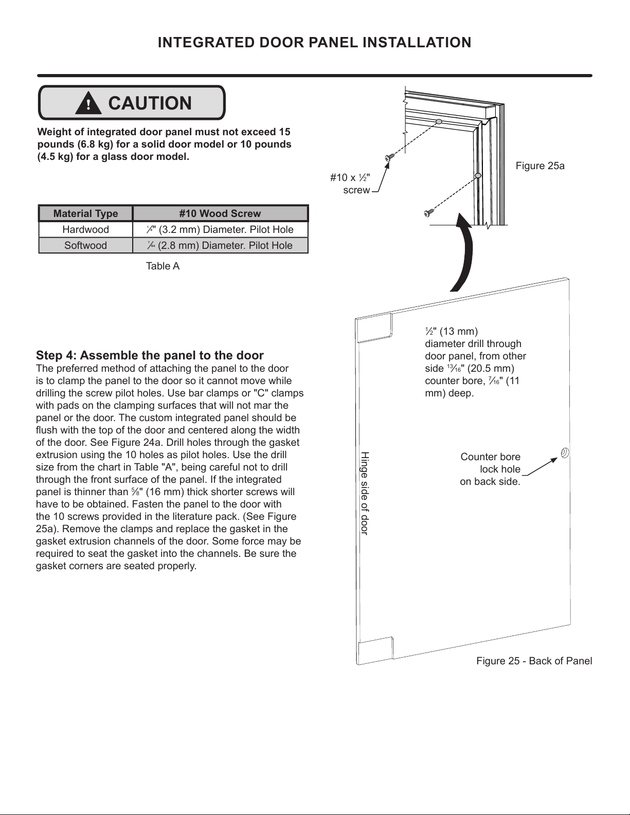
Material Type #10 Wood Screw
Hardwood
¹
" (3.2 mm) Diameter. Pilot Hole
Softwood
(2.8 mm) Diameter. Pilot Hole
Table A
Weight of integrated door panel must not exceed 15
pounds (6.8 kg) for a solid door model or 10 pounds
(4.5 kg) for a glass door model.
1
2"
screw
Step 4: Assemble the panel to the door
The preferred method of attaching the panel to the door
is to clamp the panel to the door so it cannot move while
drilling the screw pilot holes. Use bar clamps or "C" clamps
with pads on the clamping surfaces that will not mar the
panel or the door. The custom integrated panel should be
of the door. See Figure 24a. Drill holes through the gasket
size from the chart in Table "A", being careful not to drill
through the front surface of the panel. If the integrated
panel is thinner than
5
8" (16 mm) thick shorter screws will
have to be obtained. Fasten the panel to the door with
the 10 screws provided in the literature pack. (See Figure
25a). Remove the clamps and replace the gasket in the
required to seat the gasket into the channels. Be sure the
gasket corners are seated properly.
A A
B B
C C
D D
8
8
7
7
6
6
5
5
4
4
3
3
2
2
1
1
PANEL-WOOD
DO NOT SCALE DRAWING
24 Panel
SHEET 1 OF 1
UNLESS OTHERWISE SPECIFIED:
SCALE: 1:5
WEIGHT:
REV
DWG. NO.
D
SIZE
TITLE:
NAME
DATE
COMMENTS:
Q.A.
MFG APPR.
ENG APPR.
CHECKED
DRAWN
FINISH
MATERIAL
INTERPRET GEOMETRIC
TOLERANCING PER:
DIMENSIONS ARE IN INCHES
TOLERANCES:
FRACTIONAL
ANGULAR: MACH
BEND
TWO PLACE DECIMAL
THREE PLACE DECIMAL
APPLICATION
USED ON
NEXT ASSY
PROPRIETARY AND CONFIDENTIAL
THE INFORMATION CONTAINED IN THIS
DRAWING IS THE SOLE PROPERTY OF
<INSERT COMPANY NAME HERE>. ANY
REPRODUCTION IN PART OR AS A WHOLE
WITHOUT THE WRITTEN PERMISSION OF
<INSERT COMPANY NAME HERE> IS
PROHIBITED.
Counter bore
lock hole
on back side.
Figure 25 - Back of Panel
1
2" (13 mm)
diameter drill through
door panel, from other
side
13
16" (20.5 mm)
counter bore,
7
16" (11
mm) deep.
Hinge side of door
Figure 25a
14
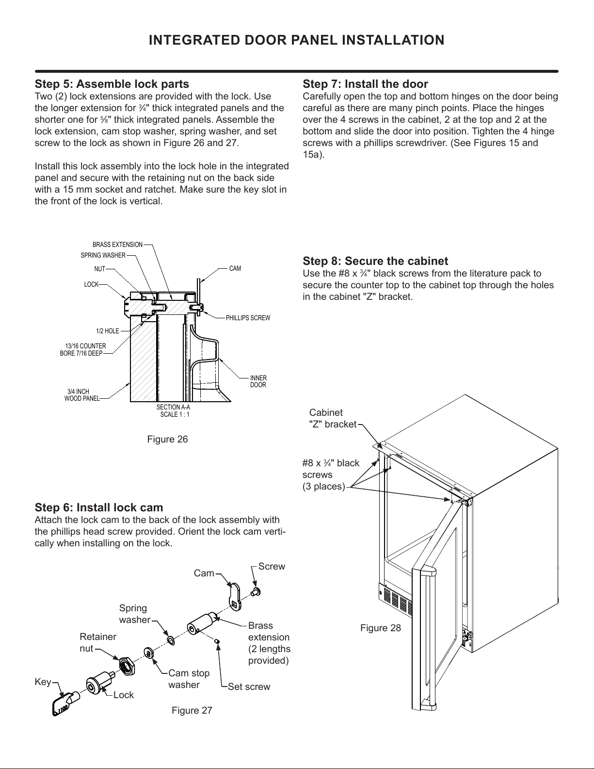
Cabinet
"Z" bracket
3
4" black
screws
(3 places)
Figure 28
Step 7: Install the door
Carefully open the top and bottom hinges on the door being
careful as there are many pinch points. Place the hinges
over the 4 screws in the cabinet, 2 at the top and 2 at the
bottom and slide the door into position. Tighten the 4 hinge
screws with a phillips screwdriver. (See Figures 15 and
15a).
SECTION A-A
SCALE 1 : 1
LOCK
NUT
BRASS EXTENSION
CAM
PHILLIPS SCREW
13/16 COUNTER
BORE 7/16 DEEP
1/2 HOLE
3/4 INCH
WOOD PANEL
SPRING WASHER
INNER
DOOR
Step 8: Secure the cabinet
3
4" black screws from the literature pack to
secure the counter top to the cabinet top through the holes
in the cabinet "Z" bracket.
INTEGRATED DOOR PANEL INSTALLATION
Figure 27
Step 6: Install lock cam
Attach the lock cam to the back of the lock assembly with
the phillips head screw provided. Orient the lock cam verti-
cally when installing on the lock.
Cam stop
washer
Spring
washer
Cam
Set screw
Lock
Key
Retainer
nut
Screw
Brass
(2 lengths
provided)
Step 5: Assemble lock parts
3
4" thick integrated panels and the
shorter one for
5
8" thick integrated panels. Assemble the
screw to the lock as shown in Figure 26 and 27.
Install this lock assembly into the lock hole in the integrated
panel and secure with the retaining nut on the back side
with a 15 mm socket and ratchet. Make sure the key slot in
the front of the lock is vertical.
Figure 26
15
USING YOUR ELECTRONIC CONTROL
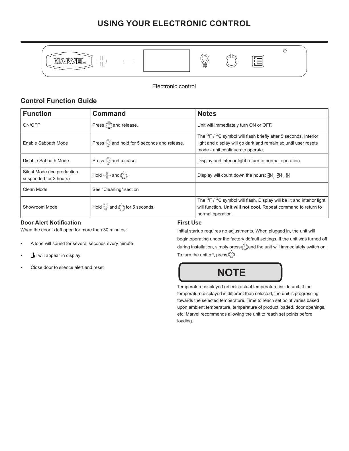
Control Function Guide
Function Command Notes
ON/OFF Press and release. Unit will immediately turn ON or OFF.
Enable Sabbath Mode Press and hold for 5 seconds and release.
The
o
F /
o
C symbol will ash briey after 5 seconds. Interior
light and display will go dark and remain so until user resets
mode - unit continues to operate.
Disable Sabbath Mode Press and release. Display and interior light return to normal operation.
Silent Mode (ice production
suspended for 3 hours)
Hold and . Display will count down the hours:
Clean Mode See "Cleaning" section
Showroom Mode Hold and for 5 seconds.
The
o
F /
o
C symbol will ash. Display will be lit and interior light
will function. Unit will not cool. Repeat command to return to
normal operation.
Door Alert Notication
When the door is left open for more than 30 minutes:
• A tone will sound for several seconds every minute
• will appear in display
• Close door to silence alert and reset
First Use
Initial startup requires no adjustments. When plugged in, the unit will
begin operating under the factory default settings. If the unit was turned o
during installation, simply press and the unit will immediately switch on.
To turn the unit o, press .
Temperature displayed reects actual temperature inside unit. If the
temperature displayed is dierent than selected, the unit is progressing
towards the selected temperature. Time to reach set point varies based
upon ambient temperature, temperature of product loaded, door openings,
etc. Marvel recommends allowing the unit to reach set points before
loading.
NOTE
Electronic control
16
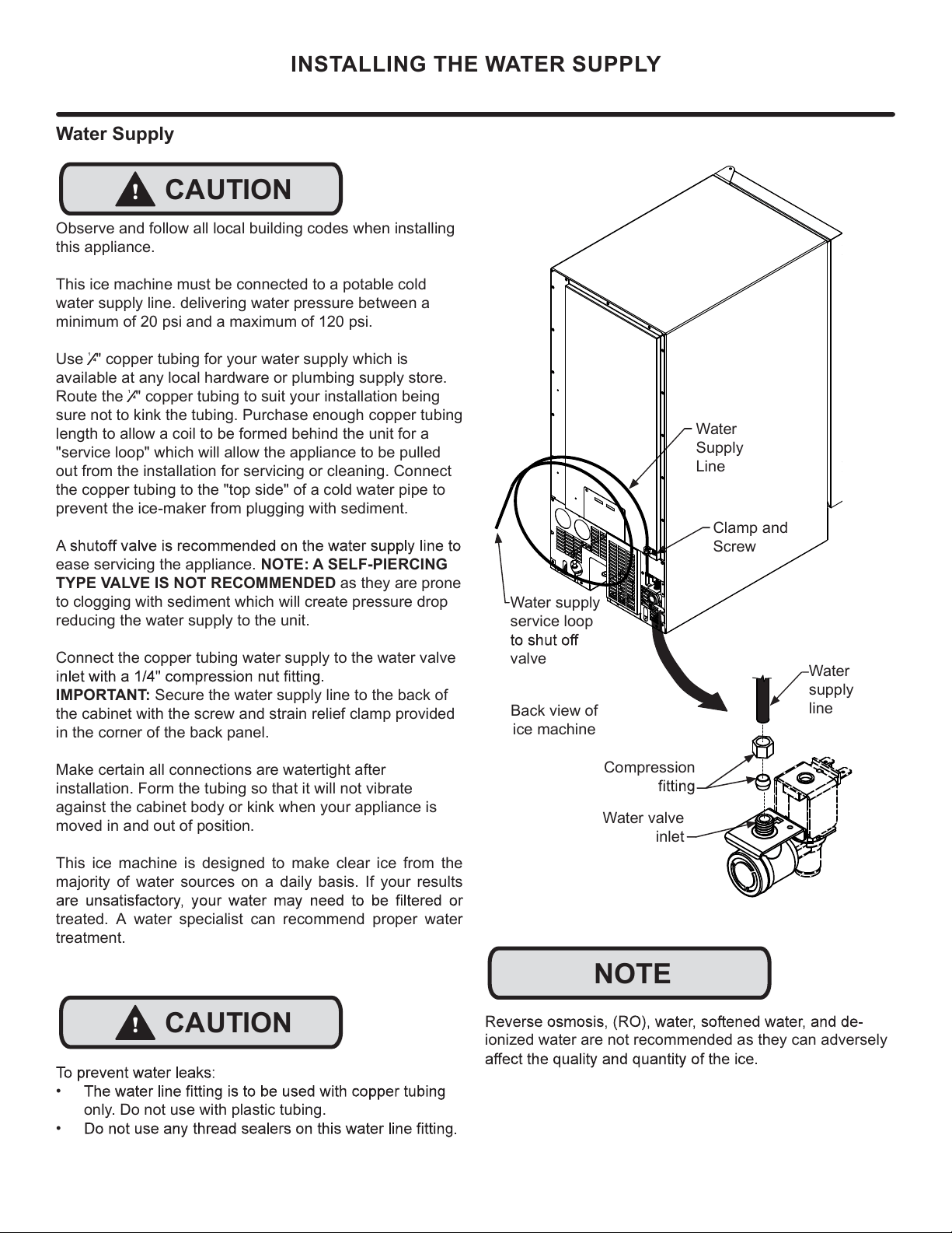
ionized water are not recommended as they can adversely
Water
Supply
Line
Clamp and
Screw
Back view of
ice machine
NOTE
!
CAUTION
INSTALLING THE WATER SUPPLY
Compression
Water
supply
line
Water supply
service loop
valve
Water valve
inlet
Water Supply
Observe and follow all local building codes when installing
this appliance.
This ice machine must be connected to a potable cold
water supply line. delivering water pressure between a
minimum of 20 psi and a maximum of 120 psi.
Use
¹
" copper tubing for your water supply which is
available at any local hardware or plumbing supply store.
Route the
¹
" copper tubing to suit your installation being
sure not to kink the tubing. Purchase enough copper tubing
length to allow a coil to be formed behind the unit for a
"service loop" which will allow the appliance to be pulled
out from the installation for servicing or cleaning. Connect
the copper tubing to the "top side" of a cold water pipe to
prevent the ice-maker from plugging with sediment.
ease servicing the appliance. NOTE: A SELF-PIERCING
TYPE VALVE IS NOT RECOMMENDED as they are prone
to clogging with sediment which will create pressure drop
reducing the water supply to the unit.
Connect the copper tubing water supply to the water valve
IMPORTANT: Secure the water supply line to the back of
the cabinet with the screw and strain relief clamp provided
in the corner of the back panel.
Make certain all connections are watertight after
installation. Form the tubing so that it will not vibrate
against the cabinet body or kink when your appliance is
moved in and out of position.
This ice machine is designed to make clear ice from the
majority of water sources on a daily basis. If your results
treated. A water specialist can recommend proper water
treatment.
!
CAUTION
•
only. Do not use with plastic tubing.
•
17
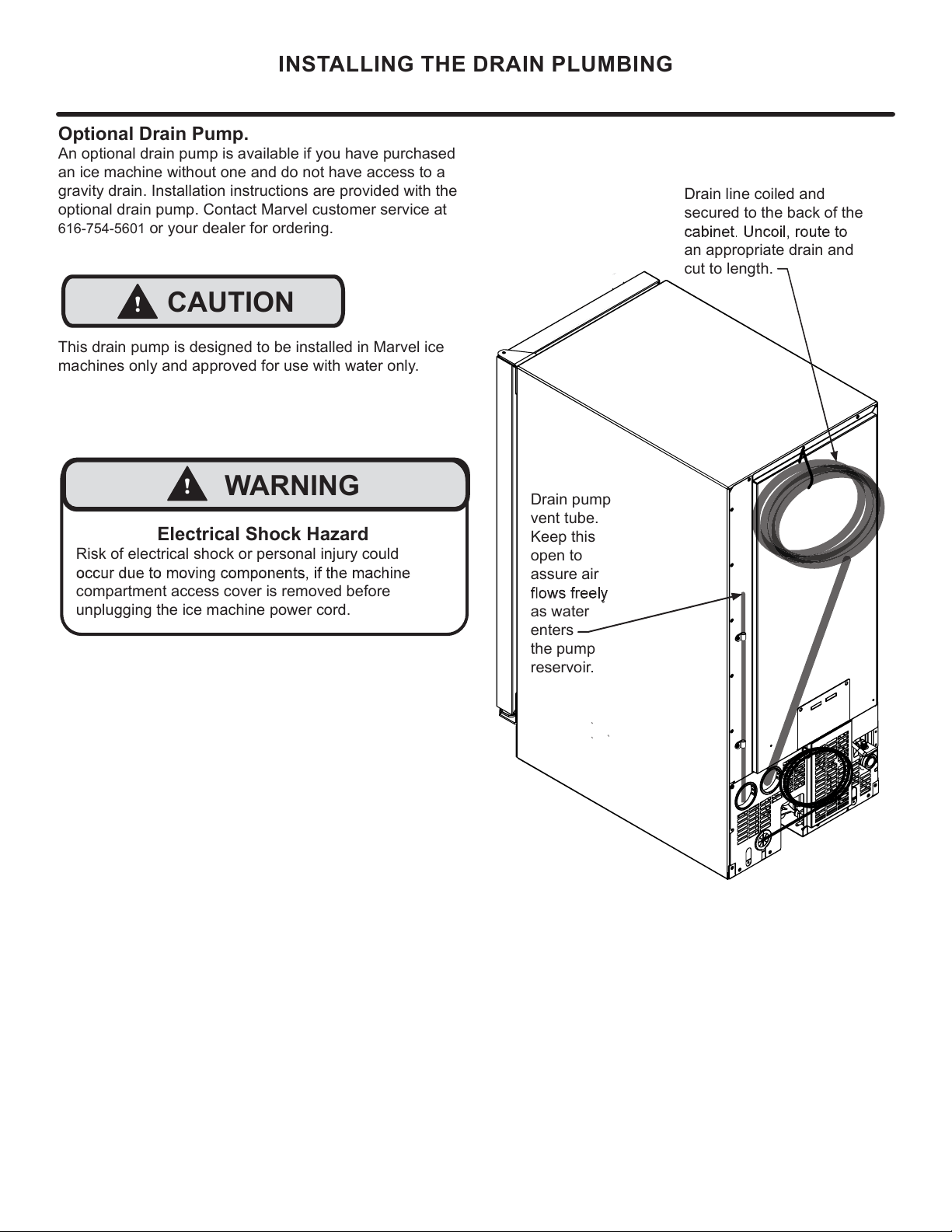
INSTALLING THE DRAIN PLUMBING
This drain pump is designed to be installed in Marvel ice
machines only and approved for use with water only.
!
CAUTION
Drain pump
vent tube.
Keep this
open to
assure air
as water
enters
the pump
reservoir.
Drain line coiled and
secured to the back of the
an appropriate drain and
cut to length.
Optional Drain Pump.
An optional drain pump is available if you have purchased
an ice machine without one and do not have access to a
gravity drain. Installation instructions are provided with the
optional drain pump. Contact Marvel customer service at
616-754-5601
or your dealer for ordering.
Electrical Shock Hazard
Risk of electrical shock or personal injury could
compartment access cover is removed before
unplugging the ice machine power cord.
!
WARNING
18
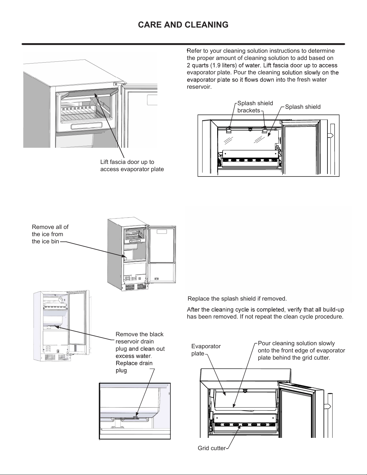
CARE AND CLEANING
Remove all of
the ice from
the ice bin
Remove the black
reservoir drain
plug
has been removed. If not repeat the clean cycle procedure.
ICE
CLEAN
OFF
Refer to your cleaning solution instructions to determine
the proper amount of cleaning solution to add based on
evaporator plate. Pour the cleaning
the fresh water
reservoir.
Splash shield
brackets
Pour cleaning solution slowly
onto the front edge of evaporator
plate behind the grid cutter.
Evaporator
plate
Grid cutter
Splash shield
Lift fascia door up to
access evaporator plate
Replace the splash shield if removed.
19
CARE AND CLEANING
Front Grille
vacuum lint and dirt from the front grille area
SHOCK HAZARD: Disconnect electrical power from the
appliance before cleaning with soap and water.
Cabinet
The painted cabinet can be washed with either a mild soap
and water and thoroughly rinsed with clear water. NEVER
use abrasive scouring cleaners.
Cleaning
Routine cleaning of the stainless steel surfaces will serve
to greatly extend the life of your product by removing
contaminants. This is especially important in coastal areas
which can expose the stainless to sever contaminants such
as halide salts (sodium chloride).
It is strongly recommended to periodically inspect and
showing signs of corrosion should be replaced.
Interior
Wash interior compartment with mild soap and water. Do
undiluted detergent or chlorine based cleaners.
Care of Appliance
1.
hinges or tip the appliance.
2.
mopping near the front of the appliance. Damage to the
grille can occur.
3. Periodically clean the interior of the appliance as
needed.
4. Periodically check and/or clean the front grille as
needed.
In the Event of a Power Failure
possible. Minimize the number of door openings while the
temperature.
Light assembly replacement
All models use LED lamps to illuminate the interior of the
of the LED.
!
CAUTION
Energy Saving Tips
The following suggestions will minimize the
cost of operating your ice machine appliance.
1.
sources.
2. Install product out of direct sunlight.
3. Assure the front grille vents at front of the ice machine
beneath the door are not obstructed and kept clean to
allow ventilation for the refrigeration system to expel
heat.
4. Plug your appliance into a dedicated power circuit. (Not
shared with other appliances).
5. Minimize door openings and duration of door openings.
6.
time.
7.
If Service is Required:
•
please contact your dealer or call Marvel Customer
Service at 616-754-5601 for directions on how to obtain
warranty coverage in your area.
•
recommendations of service centers in your area. A
listing of authorized service centers is also available at
www.marvelrefrigeration.com under the service and
support section.
•
purchase.
• Try to have information or description of nature of the
• Table is provided for recording pertinent
information regarding your product for future reference.
For Your Records
Date of Purchase
Dealer’s name
Dealer’s Address
Dealer’s City
Dealer’s State
Dealer’s Zip Code
Appliance Serial Number
Appliance Service Number
Date Warranty Card Sent (Must be
within 10 days of purchase).
Use the delay start function if the ice machine will not
be used for long periods of time.
20

Draining and Removing Water from the Ice-
Making System with a Gravity Drain.
1.
2.
3.
water valve.
Change the electronic control to the "CLEAN" position
for approximately one (1) minute. This will energize and
open the water valve and remove most of the water
from the water valve and the water valve’s outlet water
line to the reservoir.
4. Change the electronic control to the "OFF" position.
This will energize and open the drain valve to drain the
reservoir and the ice machine drain system.
5. Unplug the ice machine from the electrical outlet.
6. Remove the access cover from the rear of the ice
machine.
water in the ice-making system.
This ice machine must have all water drained and removed
to prevent ice machine damage as well as possible water
damage to the surrounding area in freezing conditions.
These damages are not covered under warranty.
Do not use any type of anti-freeze or other solution as a
substitution for properly draining the ice machine.
Clean the Ice Machine
Cleaning the ice machine will help prevent mold and
mildew growth as well as sanitize the ice machine for
storage or when it is put back into service.
! CAUTION
!
CAUTION
Risk of electrical shock or personal injury could occur
access cover is removed before unplugging the ice
machine.
!
WARNING
Electrocution Hazard
Back view of
ice machine
Water supply
Water
supply
line
Water valve
inlet
Access
cover
Screw
!
CAUTION
Winterization: If the unit will be exposed to temperatures
LONG TERM STORAGE AND WINTERIZATION
21
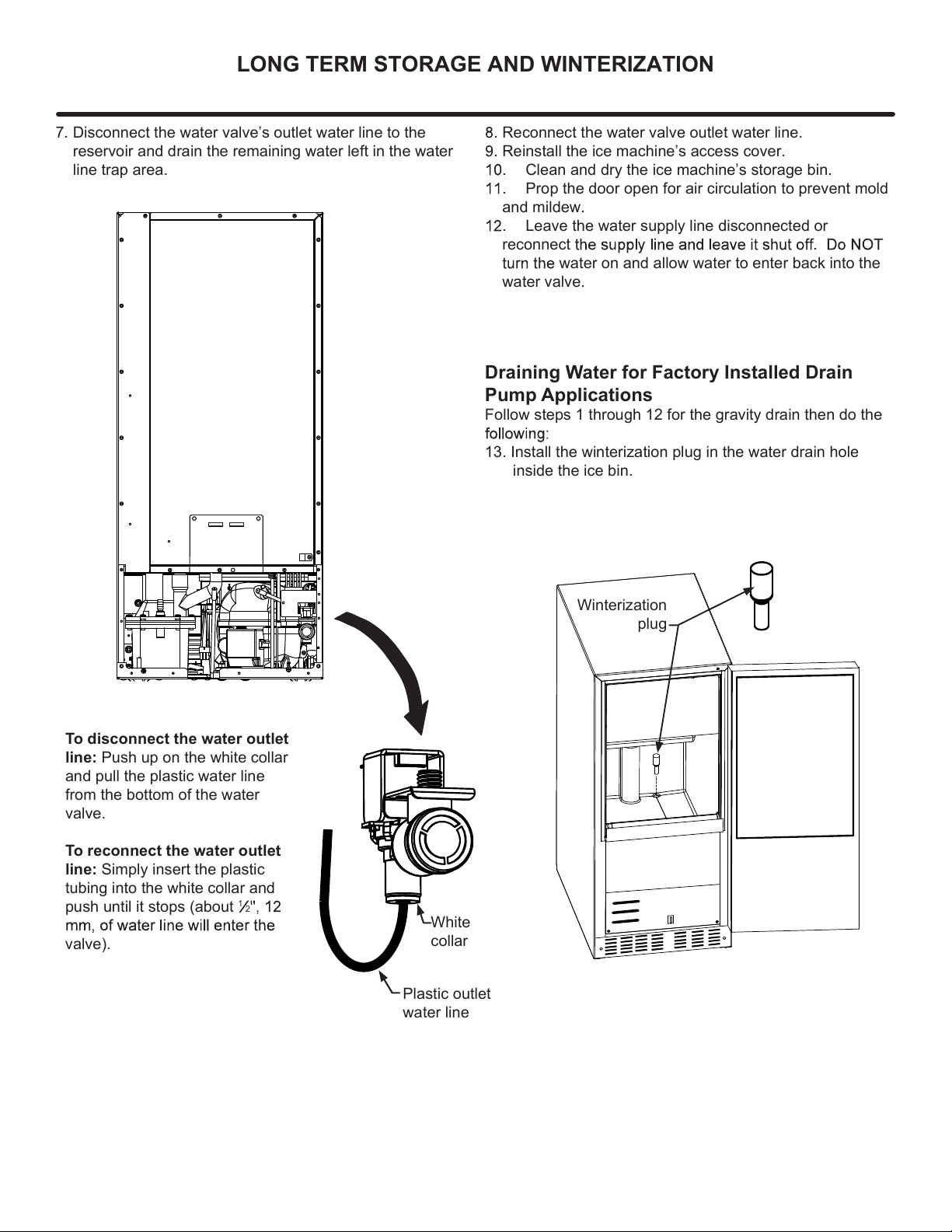
Reconnect the water valve outlet water line.
Reinstall the ice machine’s access cover.
Clean and dry the ice machine’s storage bin.
Prop the door open for air circulation to prevent mold
and mildew.
Leave the water supply line disconnected or
reconnect
water on and allow water to enter back into the
water valve.
White
collar
Plastic outlet
water line
7. Disconnect the water valve’s outlet water line to the
reservoir and drain the remaining water left in the water
line trap area.
To disconnect the water outlet
line: Push up on the white collar
and pull the plastic water line
from the bottom of the water
valve.
To reconnect the water outlet
line: Simply insert the plastic
tubing into the white collar and
push until it stops (about
1
2
valve).
Draining Water for Factory Installed Drain
Pump Applications
Follow steps 1 through 12 for the gravity drain then do the
13. Install the winterization plug in the water drain hole
inside the ice bin.
Winterization
plug
LONG TERM STORAGE AND WINTERIZATION
22
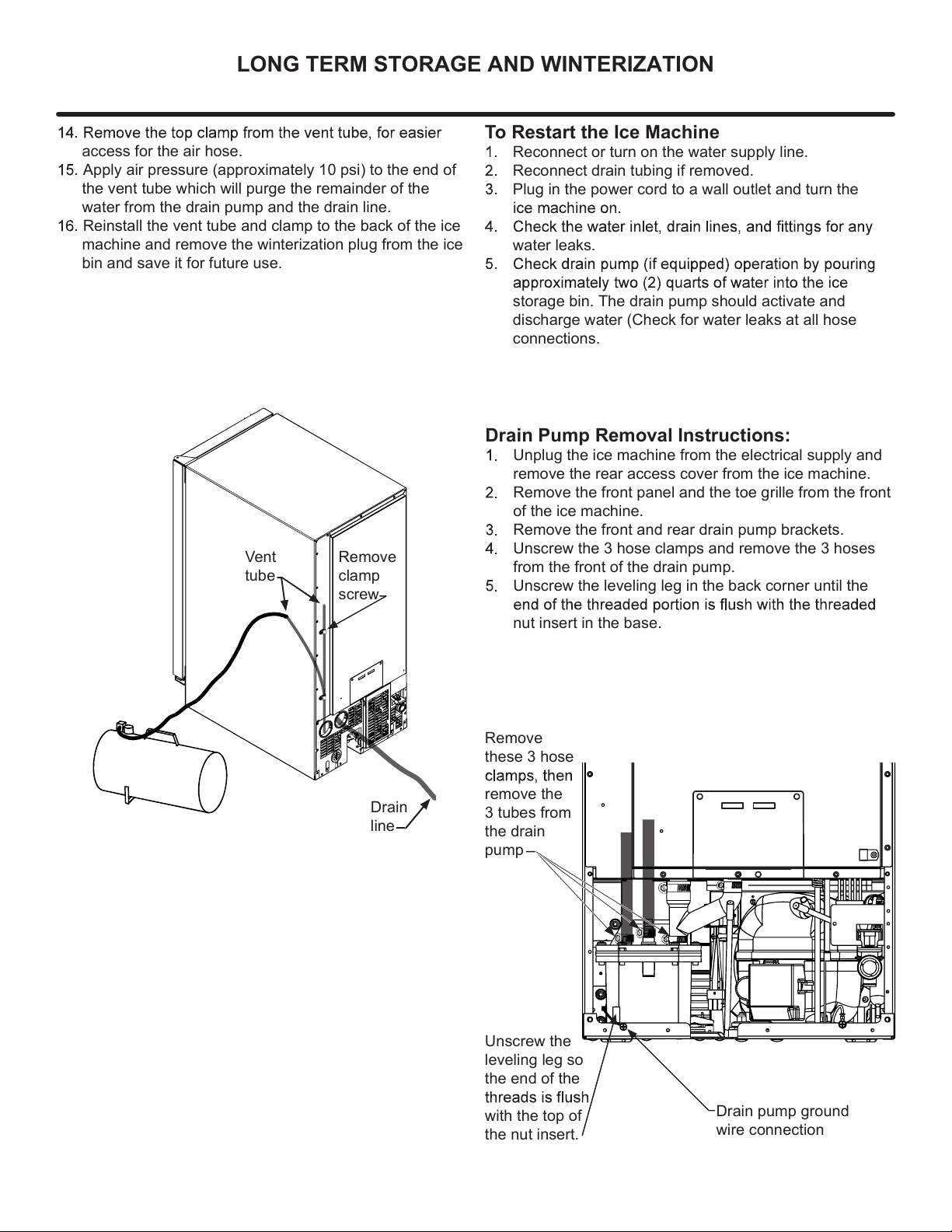
Drain Pump Removal Instructions:
Unplug the ice machine from the electrical supply and
remove the rear access cover from the ice machine.
Remove the front panel and the toe grille from the front
of the ice machine.
Remove the front and rear drain pump brackets.
Unscrew the 3 hose clamps and remove the 3 hoses
from the front of the drain pump.
Unscrew the leveling leg in the back corner until the
nut insert in the base.
To Restart the Ice Machine
Reconnect or turn on the water supply line.
Reconnect drain tubing if removed.
Plug in the power cord to a wall outlet and turn the
water leaks.
storage bin. The drain pump should activate and
discharge water (Check for water leaks at all hose
connections.
access for the air hose.
Apply air pressure (approximately 10 psi) to the end of
the vent tube which will purge the remainder of the
water from the drain pump and the drain line.
Reinstall the vent tube and clamp to the back of the ice
machine and remove the winterization plug from the ice
bin and save it for future use.
Vent
tube
Remove
clamp
screw
Drain
line
LONG TERM STORAGE AND WINTERIZATION
Unscrew the
leveling leg so
the end of the
with the top of
the nut insert.
Remove
these 3 hose
remove the
3 tubes from
the drain
pump
Drain pump ground
wire connection
23
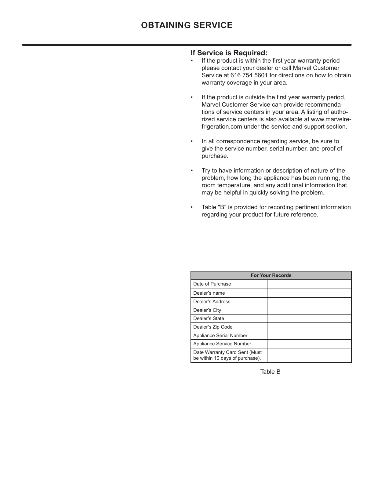
If Service is Required:
• If the product is within the rst year warranty period
please contact your dealer or call Marvel Customer
Service at 616.754.5601 for directions on how to obtain
warranty coverage in your area.
• If the product is outside the rst year warranty period,
Marvel Customer Service can provide recommenda-
tions of service centers in your area. A listing of autho-
rized service centers is also available at www.marvelre-
frigeration.com under the service and support section.
• In all correspondence regarding service, be sure to
give the service number, serial number, and proof of
purchase.
• Try to have information or description of nature of the
problem, how long the appliance has been running, the
room temperature, and any additional information that
may be helpful in quickly solving the problem.
• Table "B" is provided for recording pertinent information
regarding your product for future reference.
For Your Records
Date of Purchase
Dealer’s name
Dealer’s Address
Dealer’s City
Dealer’s State
Dealer’s Zip Code
Appliance Serial Number
Appliance Service Number
Date Warranty Card Sent (Must
be within 10 days of purchase).
Table B
OBTAINING SERVICE
24
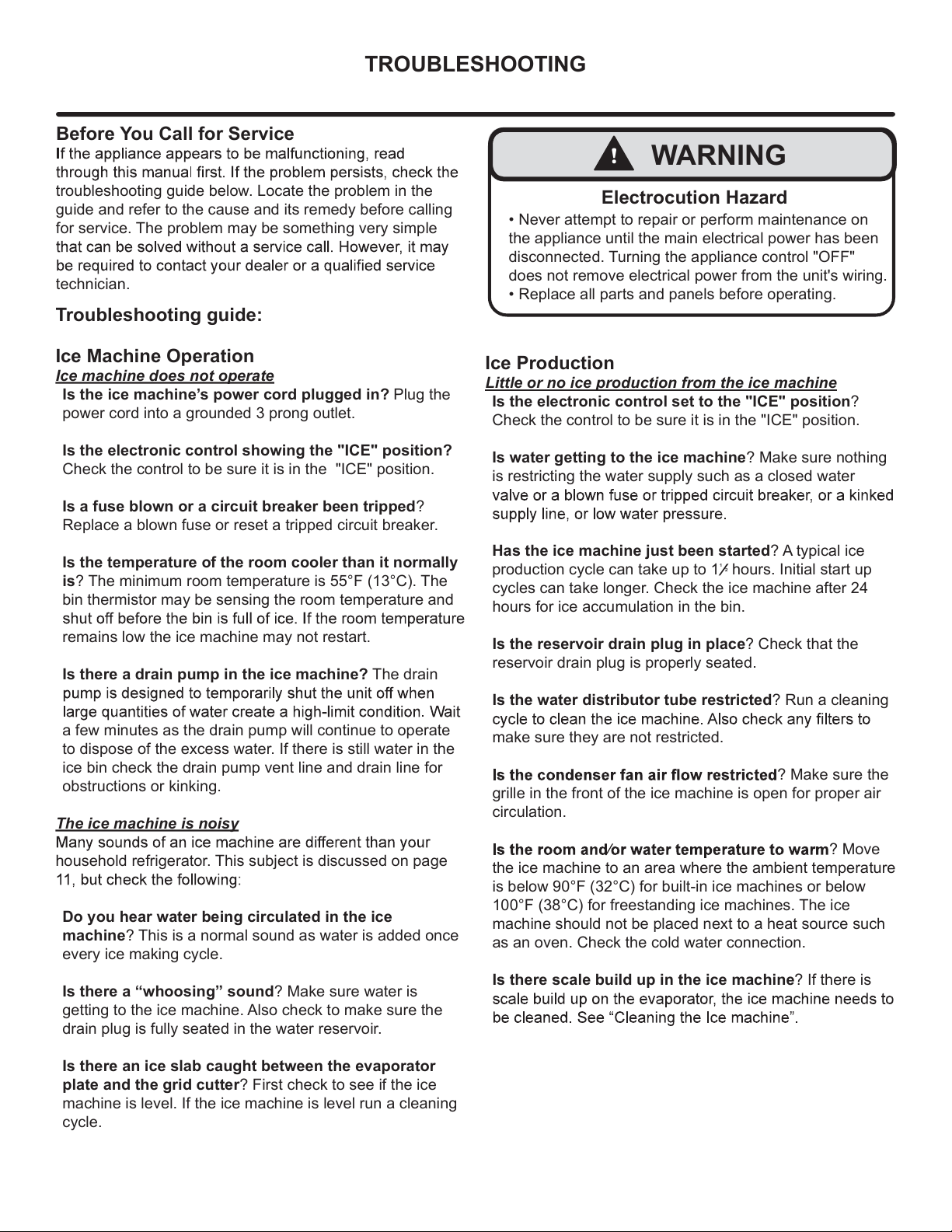
• Never attempt to repair or perform maintenance on
the appliance until the main electrical power has been
disconnected. Turning the appliance control "OFF"
does not remove electrical power from the unit's wiring.
• Replace all parts and panels before operating.
!
WARNING
Electrocution Hazard
TROUBLESHOOTING
Before You Call for Service
troubleshooting guide below. Locate the problem in the
guide and refer to the cause and its remedy before calling
for service. The problem may be something very simple
technician.
Troubleshooting guide:
Ice Machine Operation
Ice machine does not operate
Is the ice machine’s power cord plugged in? Plug the
power cord into a grounded 3 prong outlet.
Is the electronic control showing the "ICE" position?
Check the control to be sure it is in the "ICE" position.
Is a fuse blown or a circuit breaker been tripped?
Replace a blown fuse or reset a tripped circuit breaker.
Is the temperature of the room cooler than it normally
is? The minimum room temperature is 55°F (13°C). The
bin thermistor may be sensing the room temperature and
remains low the ice machine may not restart.
Is there a drain pump in the ice machine? The drain
a few minutes as the drain pump will continue to operate
to dispose of the excess water. If there is still water in the
ice bin check the drain pump vent line and drain line for
obstructions or kinking.
The ice machine is noisy
household refrigerator. This subject is discussed on page
Do you hear water being circulated in the ice
machine? This is a normal sound as water is added once
every ice making cycle.
Is there a “whoosing” sound? Make sure water is
getting to the ice machine. Also check to make sure the
drain plug is fully seated in the water reservoir.
Is there an ice slab caught between the evaporator
plate and the grid cutter? First check to see if the ice
machine is level. If the ice machine is level run a cleaning
cycle.
Ice Production
Little or no ice production from the ice machine
Is the electronic control set to the "ICE" position?
Check the control to be sure it is in the "ICE" position.
Is water getting to the ice machine? Make sure nothing
is restricting the water supply such as a closed water
Has the ice machine just been started? A typical ice
production cycle can take up to 1
¹
²
hours. Initial start up
cycles can take longer. Check the ice machine after 24
hours for ice accumulation in the bin.
Is the reservoir drain plug in place? Check that the
reservoir drain plug is properly seated.
Is the water distributor tube restricted? Run a cleaning
make sure they are not restricted.
? Make sure the
grille in the front of the ice machine is open for proper air
circulation.
? Move
the ice machine to an area where the ambient temperature
is below 90°F (32°C) for built-in ice machines or below
100°F (38°C) for freestanding ice machines. The ice
machine should not be placed next to a heat source such
as an oven. Check the cold water connection.
Is there scale build up in the ice machine? If there is
25
TROUBLESHOOTING
Plumbing Problems
Is the drain hose aligned over the drain? Move the ice
machine to align the drain.
Is the ice machine draining properly? Check that there
are no kinks or restrictions in the drain lines; this can
cause water to back up in the ice bin. Check that foreign
material is not blocking the ice bin drain located at the
right rear corner of the ice bin. Check the drain pump
discharge and vent line or any restrictions or kinks. Check
that the drain pump is level.
they cannot be repaired by the service technician. A
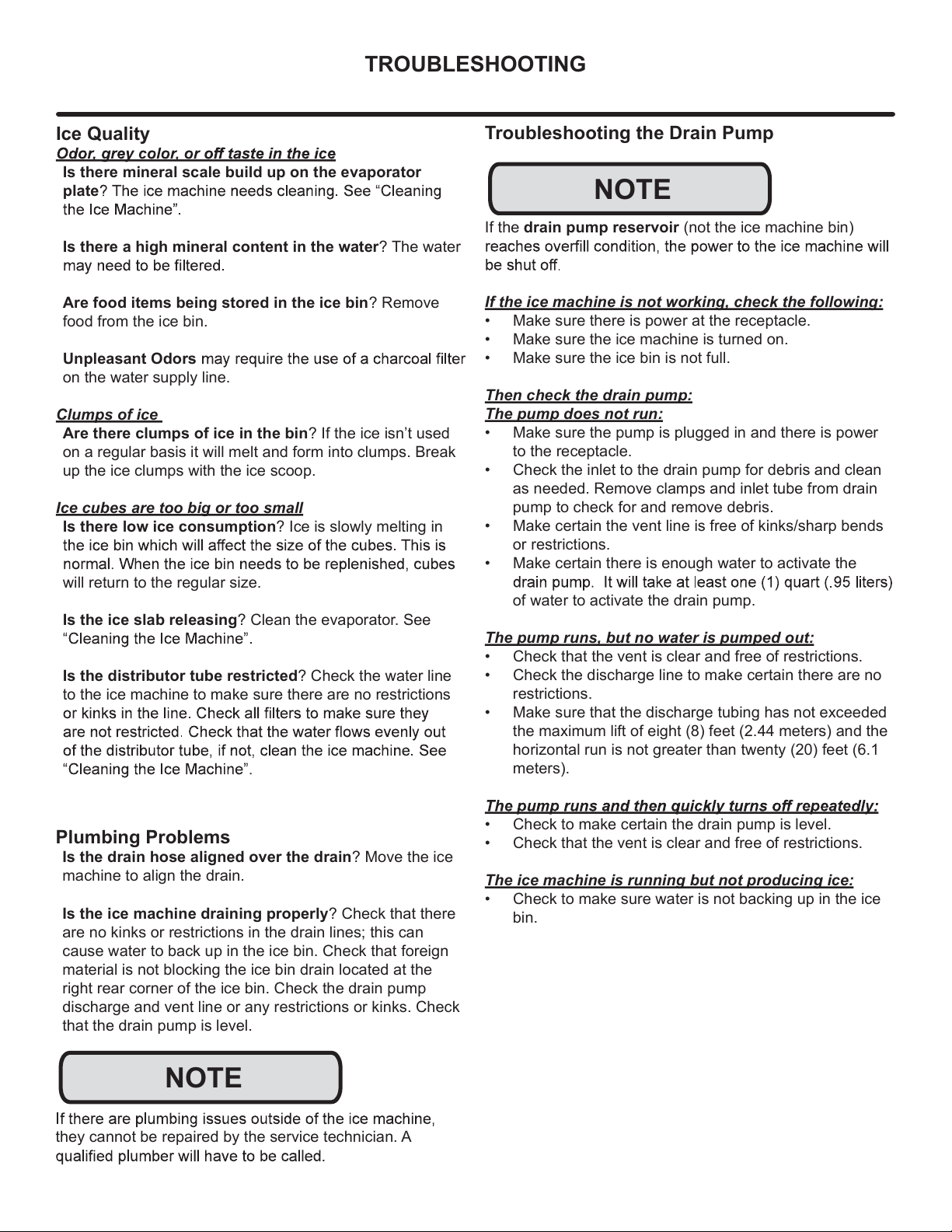
Ice Quality
Is there mineral scale build up on the evaporator
plate
Is there a high mineral content in the water? The water
Are food items being stored in the ice bin? Remove
food from the ice bin.
Unpleasant Odors
on the water supply line.
Clumps of ice
Are there clumps of ice in the bin? If the ice isn’t used
on a regular basis it will melt and form into clumps. Break
up the ice clumps with the ice scoop.
Ice cubes are too big or too small
Is there low ice consumption? Ice is slowly melting in
will return to the regular size.
Is the ice slab releasing? Clean the evaporator. See
Is the distributor tube restricted? Check the water line
to the ice machine to make sure there are no restrictions
Troubleshooting the Drain Pump
If the drain pump reservoir (not the ice machine bin)
If the ice machine is not working, check the following:
• Make sure there is power at the receptacle.
• Make sure the ice machine is turned on.
• Make sure the ice bin is not full.
Then check the drain pump:
The pump does not run:
• Make sure the pump is plugged in and there is power
to the receptacle.
• Check the inlet to the drain pump for debris and clean
as needed. Remove clamps and inlet tube from drain
pump to check for and remove debris.
• Make certain the vent line is free of kinks/sharp bends
or restrictions.
• Make certain there is enough water to activate the
of water to activate the drain pump.
The pump runs, but no water is pumped out:
• Check that the vent is clear and free of restrictions.
• Check the discharge line to make certain there are no
restrictions.
• Make sure that the discharge tubing has not exceeded
the maximum lift of eight (8) feet (2.44 meters) and the
horizontal run is not greater than twenty (20) feet (6.1
meters).
• Check to make certain the drain pump is level.
• Check that the vent is clear and free of restrictions.
The ice machine is running but not producing ice:
• Check to make sure water is not backing up in the ice
bin.
NOTE
NOTE
26
Product Liability
E
V
G
The original refrigeration experts since 1892.
27
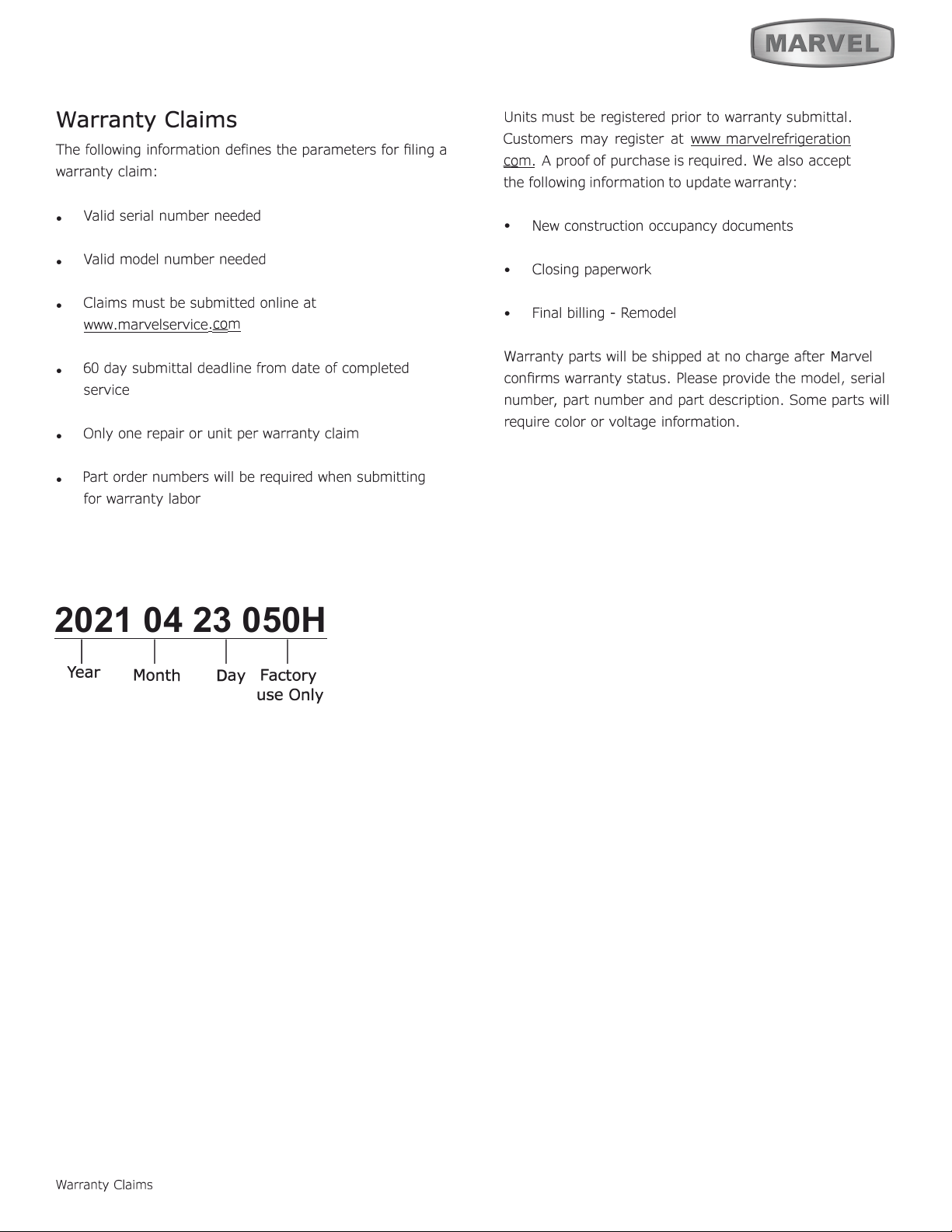
Warranty Claims
2021 04 23 050H
1 I I I
Year
Warranty Claims
D
ay
Factory
use Only
M
Month
28
Ordering Replacement Parts
O
"
"
6
6
6
M
M
M
M
m.
Ordering Replacement Parts
29
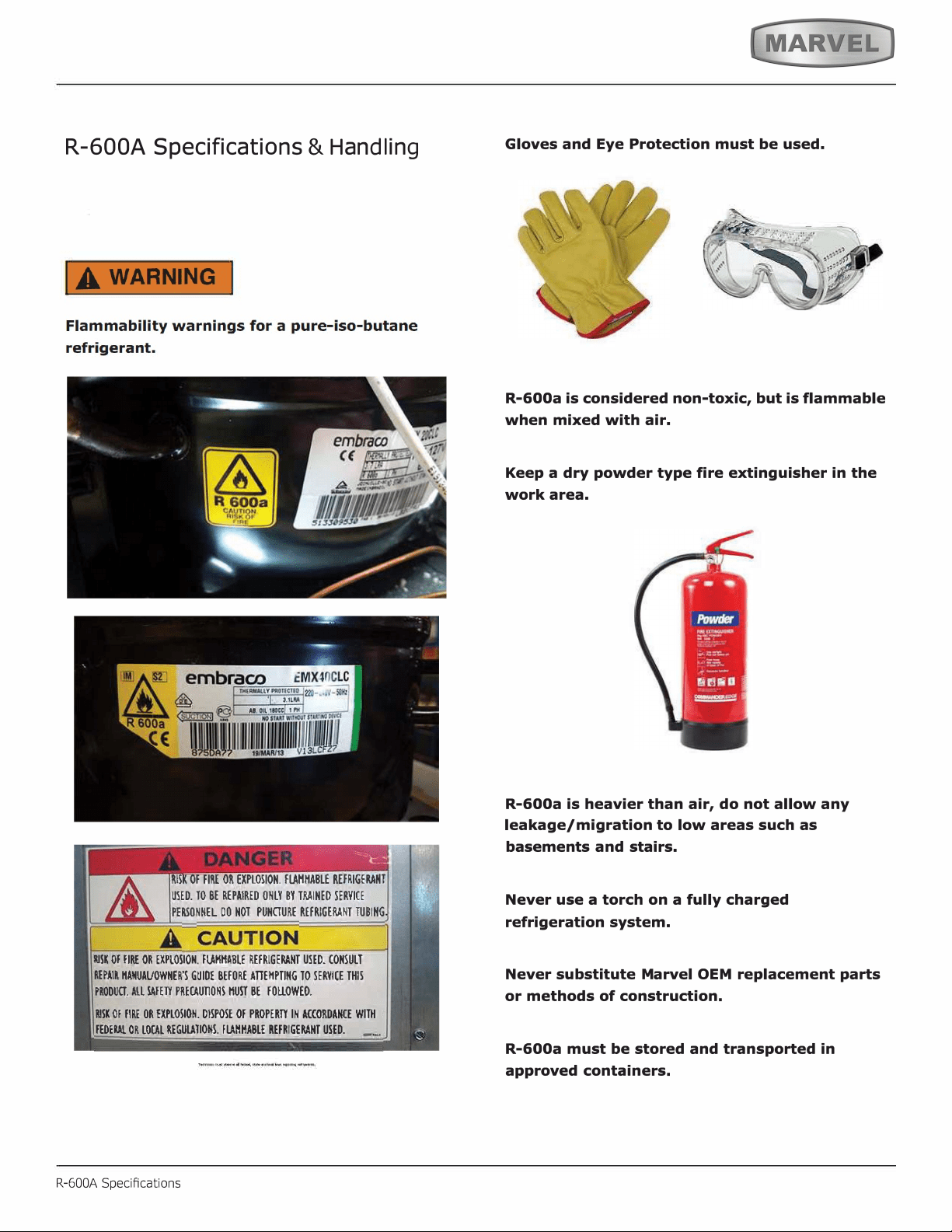
R-600A Specifications
&
H
an
dl
in
g
R-600A Specications
,
.
'
30
IA WARNING I
31
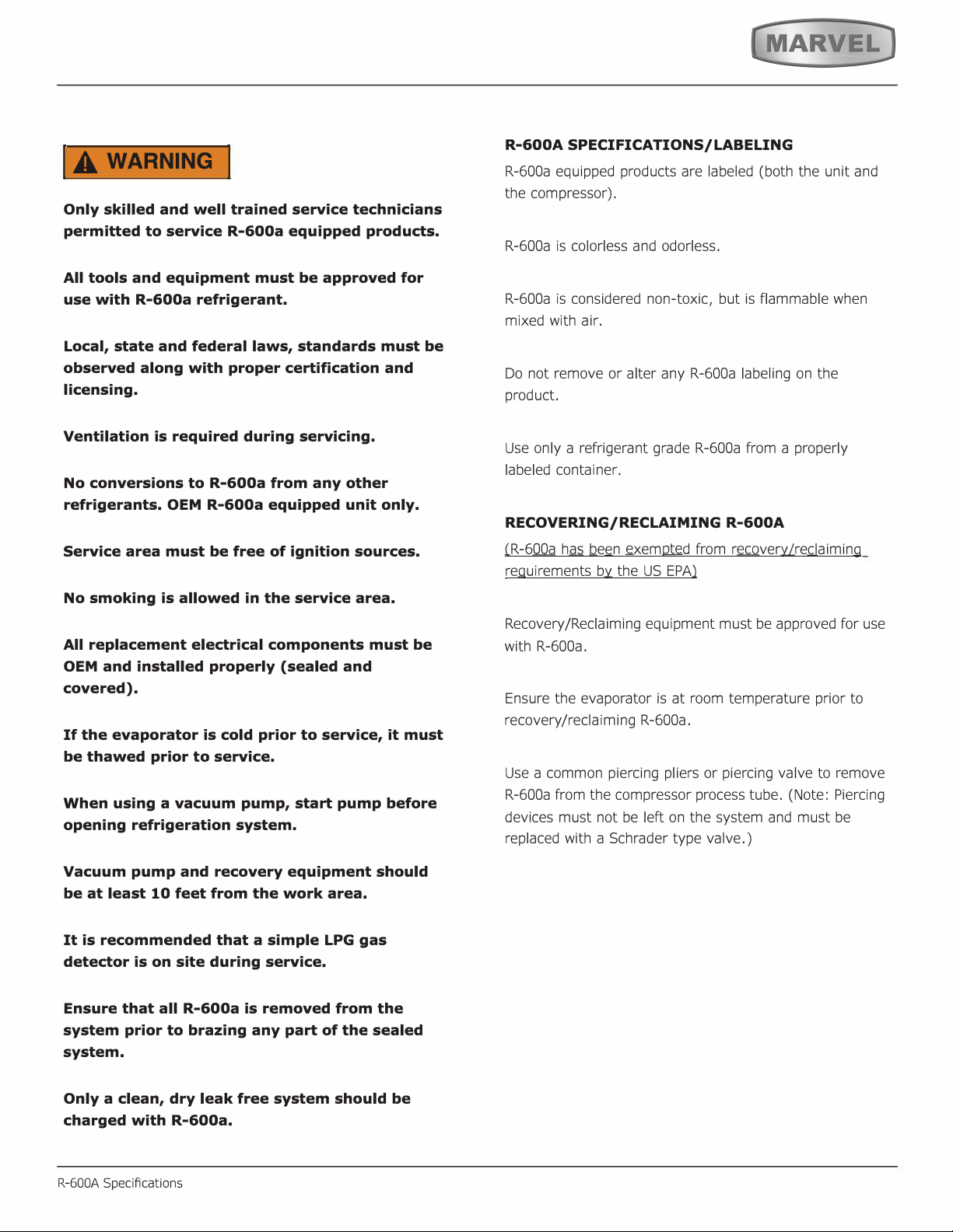
SYSTEM REPAIR
R-600A Specications
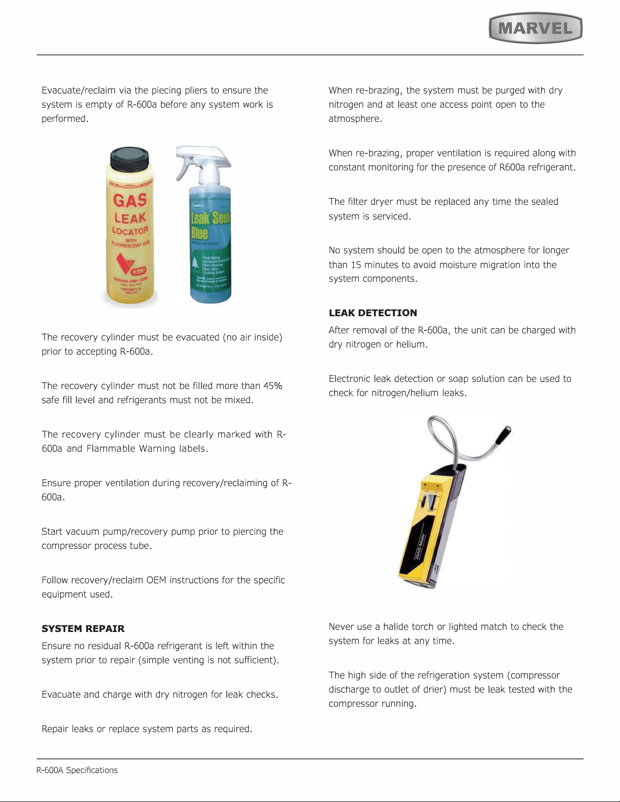
LEAK DETECTION
32
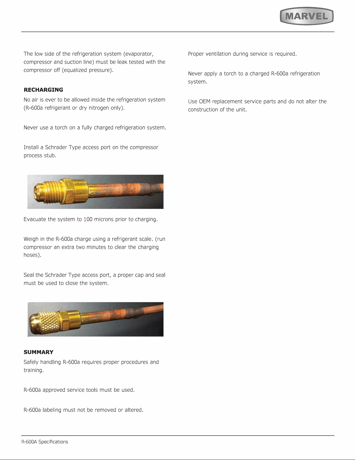
RECHARGING
SUMMARY
33
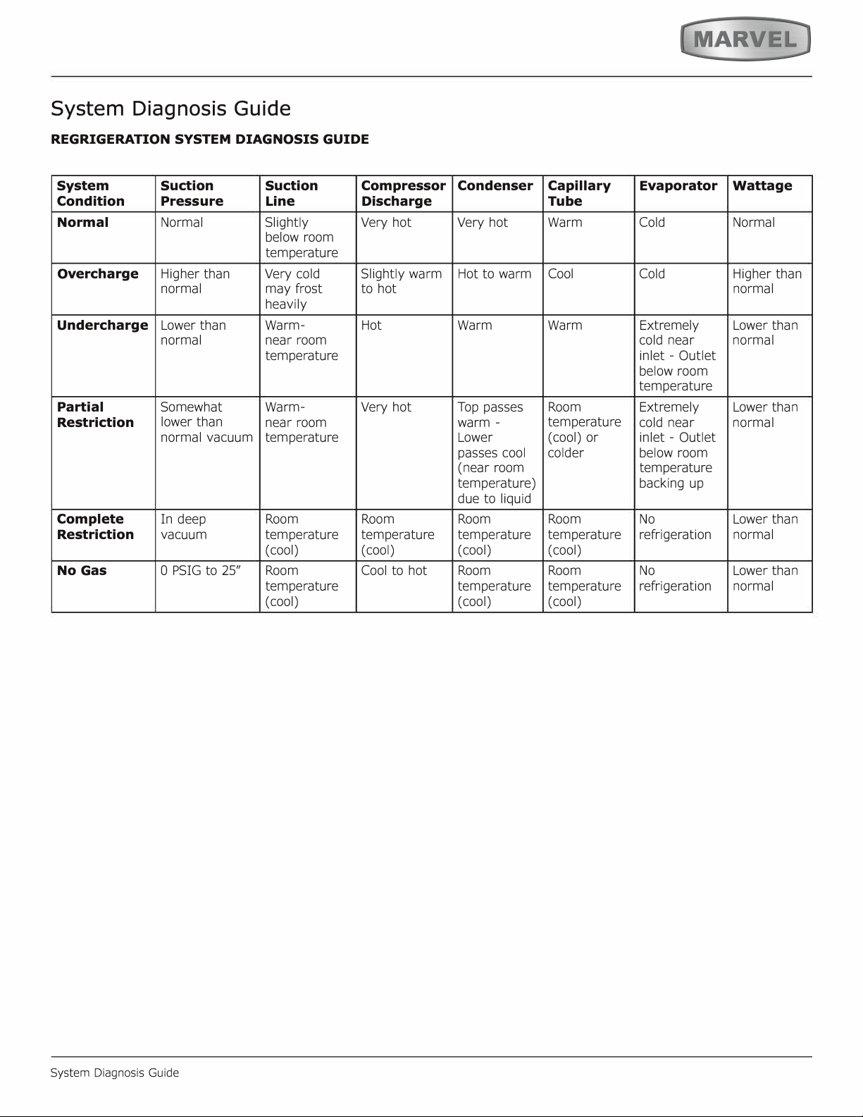
System Diagnosis Guide
System Diagnosis Guide
34
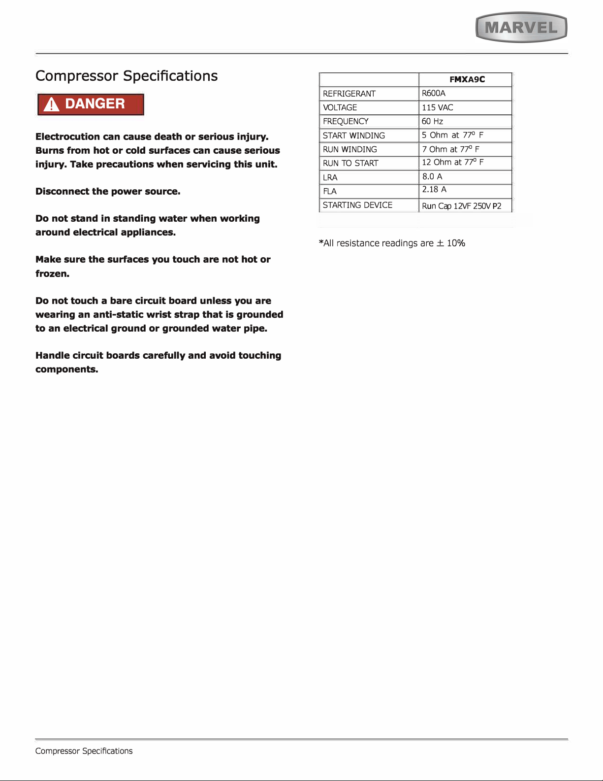
Compressor Specifications
A DANGER
F
MX
A9
C
°
°
°
8
2.18
c�
35
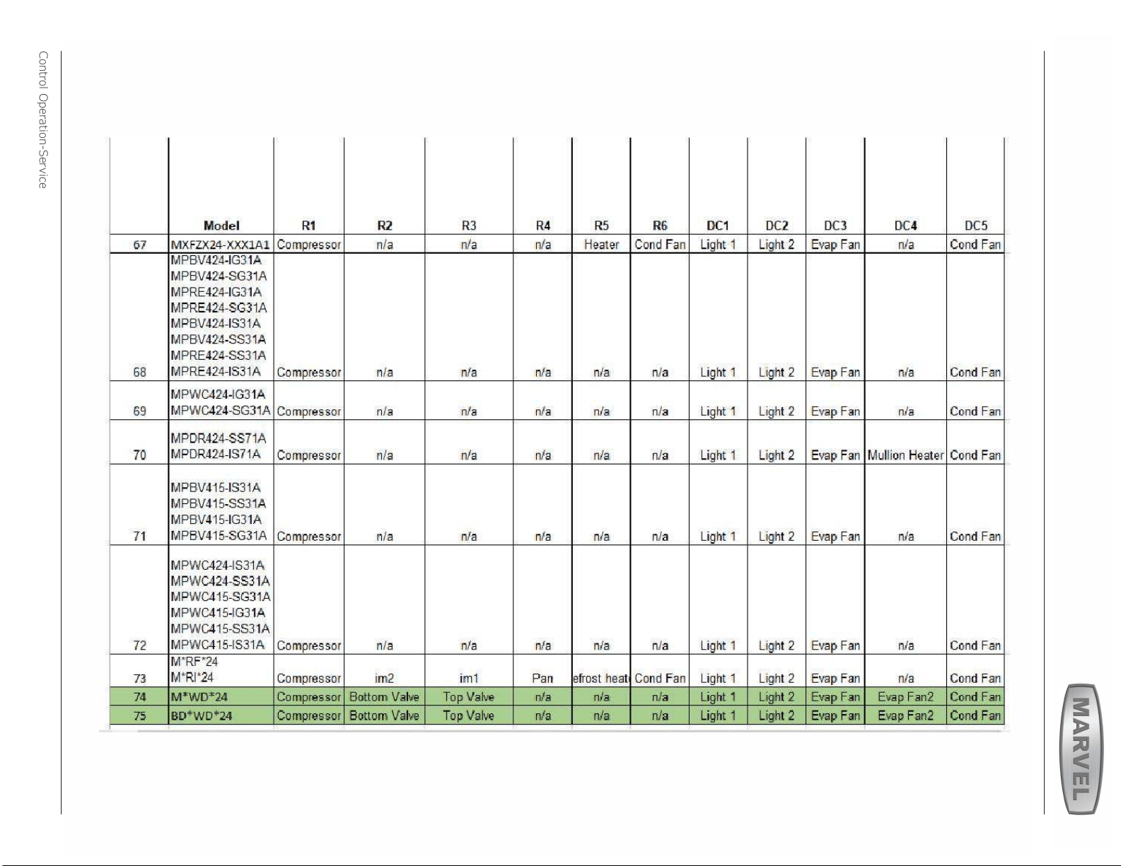
Control Operation-Service
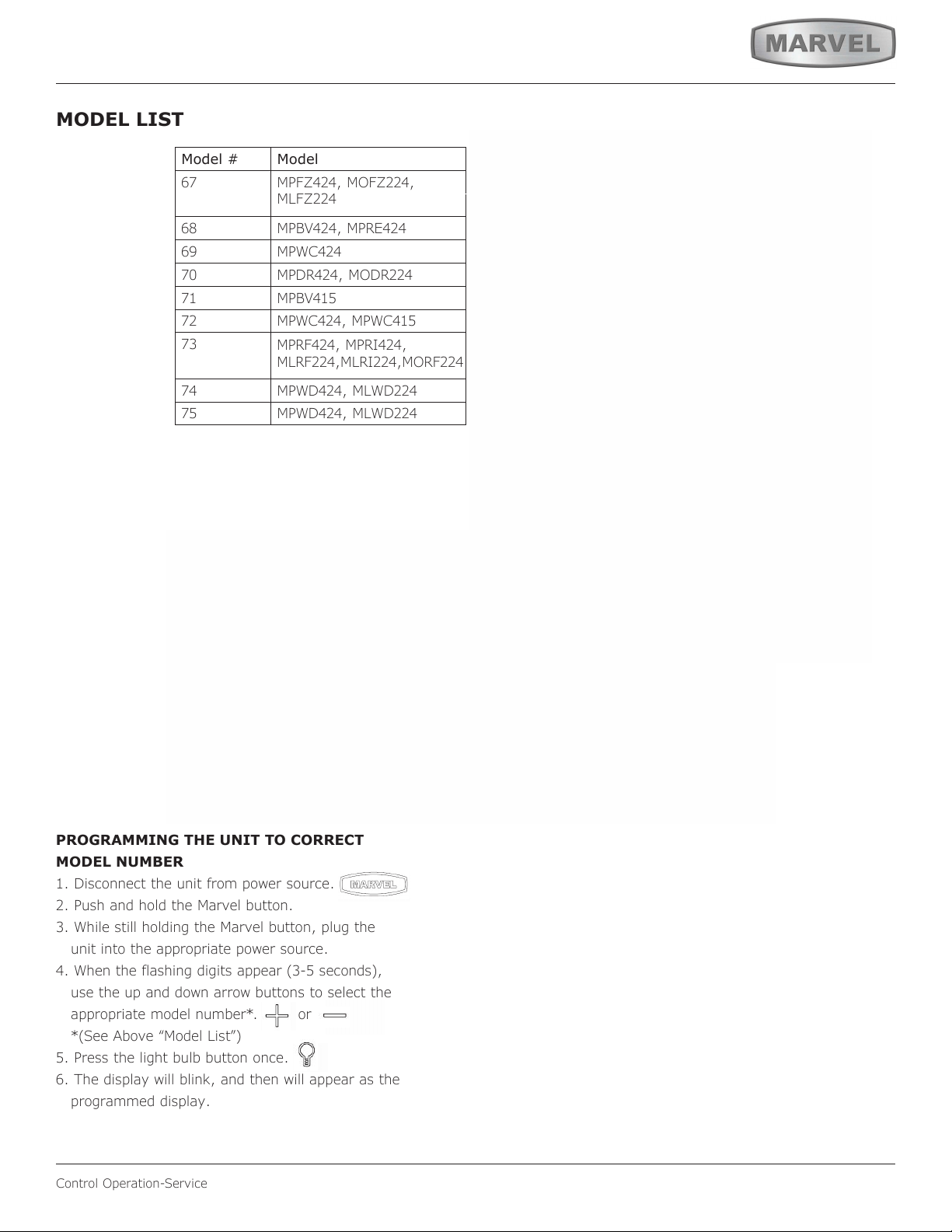
MODEL LIST
Model # Model
67
MPFZ424, MOFZ224,
MLFZ224
68
MPBV424, MPRE424
69 MPWC424
70
MPDR424, MODR224
71 MPBV415
72
MPWC424, MPWC415
73
MPRF424, MPRI424,
MLRF224,MLRI224,MORF224
74
MPWD424, MLWD224
75
MPWD424, MLWD224
17 *HRE315-***1A
18 *HRE315-***2A
19 *HRE318-***1A
20 *HRE324-***1A
21 *HRE324-***2A
22 *HRE336-***1A
23 *HRE515-***1A
24 *HRE515-***2A
25 *HRE524-***1A
26 *HRE524-***2A
27 *HRE324-***1A
28 *HRE324-***2A
29 *HKR524-***1A
30 *HKR524-***2A
31 *HWC315-***2A
32 *HWC315-***1A
33 *HWC318-***1A
34 *HWC324-***2A
35 *HWC324-***1A
36 *HWC515-***2A
37 *HWC515-***1A
38 *HWC524-***1A
39 *HWC524-***2A
40 *HWC336-***1A
41 *HBD324-***1A
42 *HBD324-***2A
43 *HBD524-***1A
44 *HBD524-***2A
45 *HWD324-***2A
46 *HWD324-***1A
47 *HWD524-***2A
48 *HWD524-***1A
49 *HRF124-***2A
50 *HRF124-***1A
51 *HRI124-***2A
52 *HRI124-***1A
53 Nugget R134A
54 Grid Ice
55 Medical Refrigerator
56 Full size
57 Nugget R600
PROGRAMMING THE UNIT TO CORRECT
MODEL NUMBER
1. Disconnect the unit from power source.
2. Push and hold the Marvel button.
3. While still holding the Marvel button, plug the
unit into the appropriate power source.
4. When the flashing digits appear (3-5 seconds),
use the up and down arrow buttons to select the
appropriate model number*. or
*(See Above “Model List”)
5. Press the light bulb button once.
6. The display will blink, and then will appear as the
programmed display.
36
USER GUIDE
u-line.com
Control Operation-Service
Program Model Relay 1 Relay 2 Relay 3 Relay 4 Relay 5 Relay 6 DC1 DC2 DC3 DC4 DC5
53
Nugget Ice, R134 Comp/Fan - Dump Valve Reservoir Fill Auger Water Main Light 1 Light 2 - - Cond Fan
57
Nugget Ice, R600 Water Main Water Dis-
pense
Dump Valve Reservoir Fill Auger Cond Fan Light 1 Light 2 - - Cond Fan
11
Clear Ice, 3 Class Compressor Water Dis-
pense
Circ Pump Water Inlet Hot Gas
Valve
Cond Fan Light 1 Light 2 - - Cond Fan
01
**BV315-***1A Compressor - - - - - Light 1 Light 2 Evap Fan - Cond Fan
03
**BV318-***1A Compressor - - - - - Light 1 Light 2 Evap Fan - Cond Fan
04
**BV324-***1A Compressor - - - - - Light 1 Light 2 Evap Fan - Cond Fan
06
**BV336-***1A Compressor Top/Left Valve Bot/Right Valve - - - Light 1 Light 2 Evap Fan Evap Fan 2 Cond Fan
07
**BV515-***1A Compressor - - - - - Light 1 Light 2 Evap Fan - Cond Fan
09
**BV524-***1A Compressor - - - - - Light 1 Light 2 Evap Fan -
Cond Fan
13
**DR324-***1A Compressor Mullion Heater - - - - Light 1 Light 2 Evap Fan Evap Fan 2 Cond Fan
15
**FZ324-***1A Compressor - - - Heater Cond Fan Light 1 Light 2 Evap Fan - Cond Fan
17
**RE315-***1A Compressor - - - - - Light 1 Light 2 Evap Fan - Cond Fan
19
**RE318-***1A Compressor - - - - - Light 1 Light 2 Evap Fan - Cond Fan
20
**RE324-***1A Compressor - - - - - Light 1 Light 2 Evap Fan - Cond Fan
22
**RE336-***1A Compressor Top/Left Valve Bot/Right Valve - - - Light 1 Light 2 Evap Fan Evap Fan 2 Cond Fan
23
**RE515-***1A Compressor - - - - - Light 1 Light 2 Evap Fan - Cond Fan
25
**RE524-***1A Compressor - - - - - Light 1 Light 2 Evap Fan - Cond Fan
27
**RE324-***1A Compressor - - - - - Light 1 Light 2 Evap Fan - Cond Fan
29
**KR524-***1A Compressor - - - - - Light 1 Light 2 Evap Fan - Cond Fan
32
**WC315-***1A Compressor
- - - - - Light 1 Light 2 Evap Fan - Cond Fan
33
**WC318-***1A Compressor - - - - - Light 1 Light 2 Evap Fan - Cond Fan
35
**WC324-***1A Compressor - - - - - Light 1 Light 2 Evap Fan - Cond Fan
37
**WC515-***1A Compressor - - - - - Light 1 Light 2 Evap Fan - Cond Fan
38
**WC524-***1A Compressor - - - - - Light 1 Light 2 Evap Fan - Cond Fan
40
**WC336-***1A Compressor Top/Left Valve Bot/Right Valve - - - Light 1 Light 2 Evap Fan Evap Fan 2 Cond Fan
41
**BD324-***1A Compressor Top/Left Valve Bot/Right Valve - - - Light 1 Light 2 Evap Fan Evap Fan 2 Cond Fan
43
**BD524-***1A Compressor Top/Left Valve Bot/Right Valve - - - Light 1 Light 2 Evap Fan Evap Fan 2 Cond Fan
46
**WD324-***1A Compressor Top/Left Valve Bot/Right Valve - - - Light 1 Light 2 Evap Fan Evap Fan 2 Cond Fan
48
**WD524-***1A Compressor Top/Left Valve Bot/Right Valve - - - Light 1 Light 2 Evap Fan Evap Fan 2 Cond Fan
50
**RF124-***1A Compressor - - Pan Defrost
Heater
Cond Fan Light 1 Light 2 Evap Fan - Cond Fan
52
**RI124-***1A Compressor Icemaker 2 Icemaker 1 Pan Defrost
Heater
Cond Fan Light 1 Light 2 Evap Fan - Cond Fan
Relay / Output Chart
37
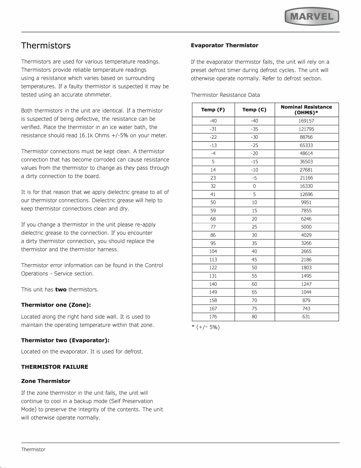
Thermistors
two
Thermistor one (Zone):
Thermistor two (Evaporator):
THERMISTOR FAILURE
Zone Thermistor
Evaporator Thermistor
Temp (F)
Temp (C)
Nominal Resistance
(OHMS)*
77
38
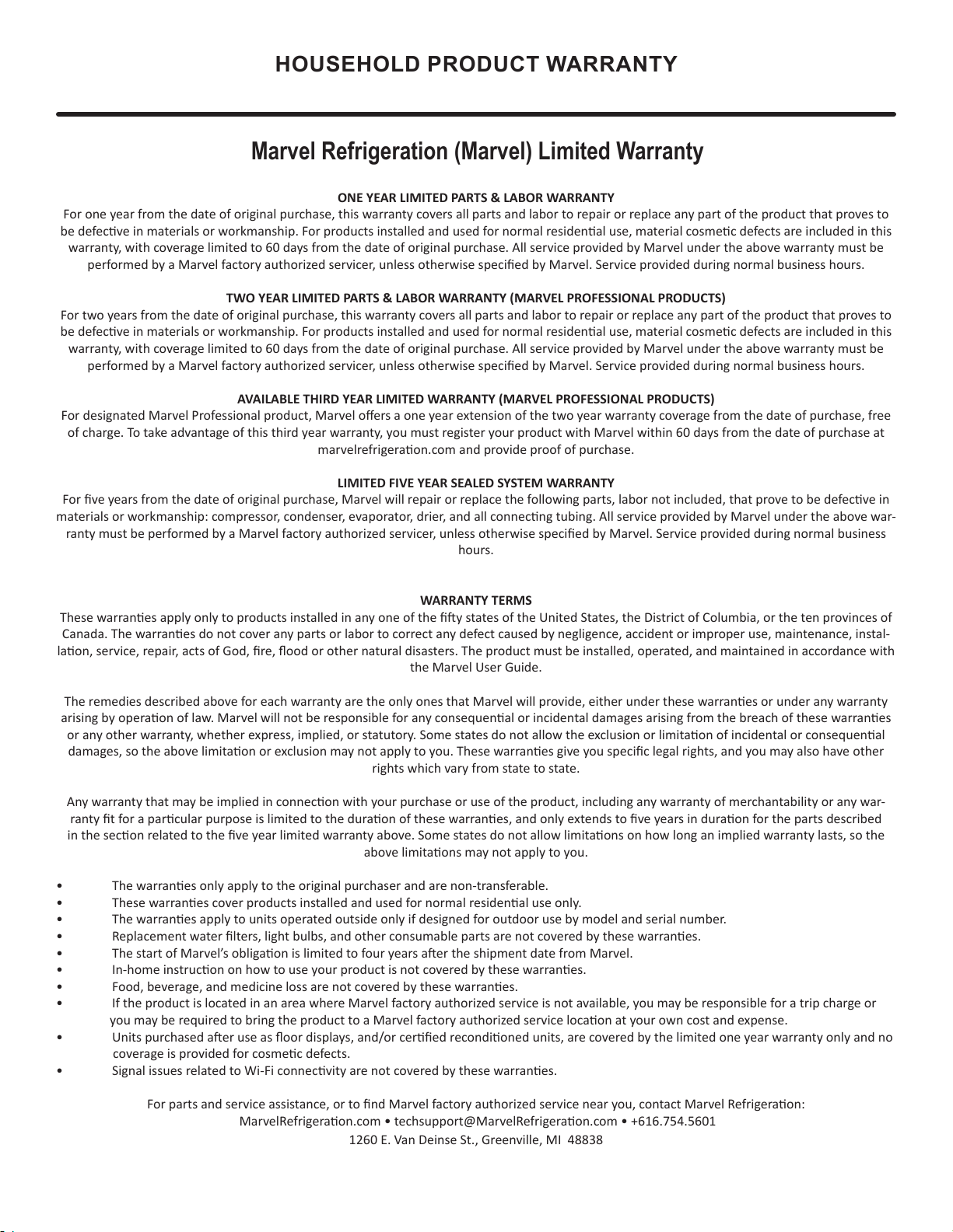
HOUSEHOLD PRODUCT WARRANTY
Marvel Refrigeration (Marvel) Limited Warranty
ONE YEAR LIMITED PARTS & LABOR WARRANTY
For one year from the date of original purchase, this warranty covers all parts and labor to repair or replace any part of the product that proves to
be defecve in materials or workmanship. For products installed and used for normal residenal use, material cosmec defects are included in this
warranty, with coverage limited to 60 days from the date of original purchase. All service provided by Marvel under the above warranty must be
performed by a Marvel factory authorized servicer, unless otherwise specied by Marvel. Service provided during normal business hours.
TWO YEAR LIMITED PARTS & LABOR WARRANTY (MARVEL PROFESSIONAL PRODUCTS)
For two years from the date of original purchase, this warranty covers all parts and labor to repair or replace any part of the product that proves to
be defecve in materials or workmanship. For products installed and used for normal residenal use, material cosmec defects are included in this
warranty, with coverage limited to 60 days from the date of original purchase. All service provided by Marvel under the above warranty must be
performed by a Marvel factory authorized servicer, unless otherwise specied by Marvel. Service provided during normal business hours.
AVAILABLE THIRD YEAR LIMITED WARRANTY (MARVEL PROFESSIONAL PRODUCTS)
For designated Marvel Professional product, Marvel oers a one year extension of the two year warranty coverage from the date of purchase, free
of charge. To take advantage of this third year warranty, you must register your product with Marvel within 60 days from the date of purchase at
marvelrefrigeraon.com and provide proof of purchase.
LIMITED FIVE YEAR SEALED SYSTEM WARRANTY
For ve years from the date of original purchase, Marvel will repair or replace the following parts, labor not included, that prove to be defecve in
materials or workmanship: compressor, condenser, evaporator, drier, and all connecng tubing. All service provided by Marvel under the above war-
ranty must be performed by a Marvel factory authorized servicer, unless otherwise specied by Marvel. Service provided during normal business
hours.
WARRANTY TERMS
These warranes apply only to products installed in any one of the y states of the United States, the District of Columbia, or the ten provinces of
Canada. The warranes do not cover any parts or labor to correct any defect caused by negligence, accident or improper use, maintenance, instal-
laon, service, repair, acts of God, re, ood or other natural disasters. The product must be installed, operated, and maintained in accordance with
the Marvel User Guide.
The remedies described above for each warranty are the only ones that Marvel will provide, either under these warranes or under any warranty
arising by operaon of law. Marvel will not be responsible for any consequenal or incidental damages arising from the breach of these warranes
or any other warranty, whether express, implied, or statutory. Some states do not allow the exclusion or limitaon of incidental or consequenal
damages, so the above limitaon or exclusion may not apply to you. These warranes give you specic legal rights, and you may also have other
rights which vary from state to state.
Any warranty that may be implied in connecon with your purchase or use of the product, including any warranty of merchantability or any war-
ranty t for a parcular purpose is limited to the duraon of these warranes, and only extends to ve years in duraon for the parts described
in the secon related to the ve year limited warranty above. Some states do not allow limitaons on how long an implied warranty lasts, so the
above limitaons may not apply to you.
• The warranes only apply to the original purchaser and are non-transferable.
• These warranes cover products installed and used for normal residenal use only.
• The warranes apply to units operated outside only if designed for outdoor use by model and serial number.
• Replacement water lters, light bulbs, and other consumable parts are not covered by these warranes.
• The start of Marvel’s obligaon is limited to four years aer the shipment date from Marvel.
• In-home instrucon on how to use your product is not covered by these warranes.
• Food, beverage, and medicine loss are not covered by these warranes.
• If the product is located in an area where Marvel factory authorized service is not available, you may be responsible for a trip charge or
you may be required to bring the product to a Marvel factory authorized service locaon at your own cost and expense.
• Units purchased aer use as oor displays, and/or cered recondioned units, are covered by the limited one year warranty only and no
coverage is provided for cosmec defects.
• Signal issues related to Wi-Fi connecvity are not covered by these warranes.
For parts and service assistance, or to nd Marvel factory authorized service near you, contact Marvel Refrigeraon:
MarvelRefrigeraon.com • techsupport@MarvelRefrigeraon.com • +616.754.5601
1260 E. Van Deinse St., Greenville, MI 48838
39
Marvel Refrigeration
All specications and product designs subject to change without notice. Such revisions do not entitle
the buyer to corresponding changes, improvements, additions, replacements or compensation for
previously purchased products.
www.marvelrefrigeration.com
1260 E. Van Deinse St.
Greenville MI 48838
616.754.5601
41015651 Rev A
12/14/20
40