Page 1
Compact
of
Disassembly
Round Flow Cassette (9000, 12000, 18000 BTU sizes)
1. Front Panel and Display Board
Pr
ocedur
e Illustration
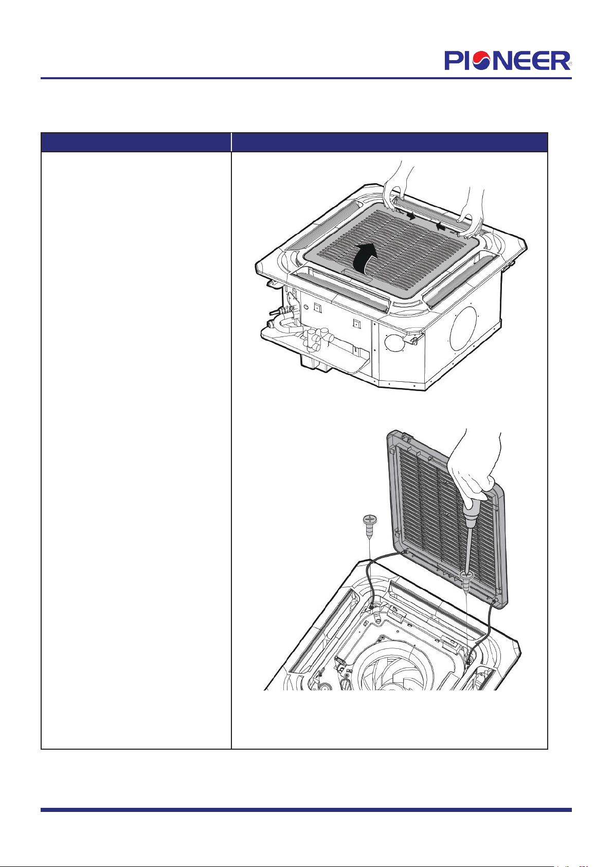
1) Release 2 hooks and open the panel.
(see Figure 1.)
2) Remove two screws of wire line
(see Figure 2.)
Figure 1
Figure 2
Note: This section is for reference only. Actual unit appearance may vary.
Disassembly Guide for CYB/CB Ceiling Cassette Air Handler (9K-18K BTU size)
Applies to Models with Nomenclature of "CB00xGMFILCFHD".
"CB01xGMFILCFHD".
Page 2
Procedure Illustration
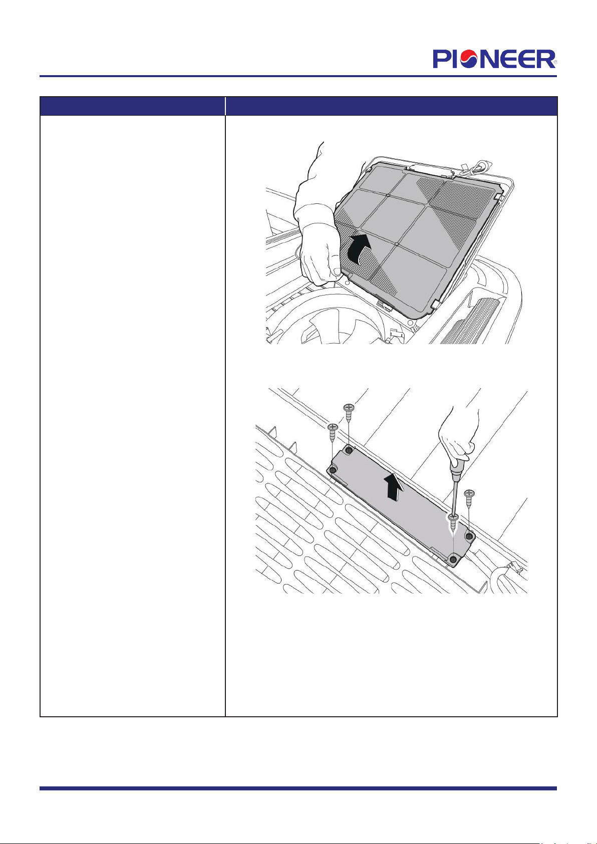
3) Release the hook then pull up
the filter (see Figure 3).
4) Remove 4 screws of cover and
remove the display board (see
Figure 4).
Figure 3
Figure 4
Note: This section is for reference only. Actual unit appearance may vary
.
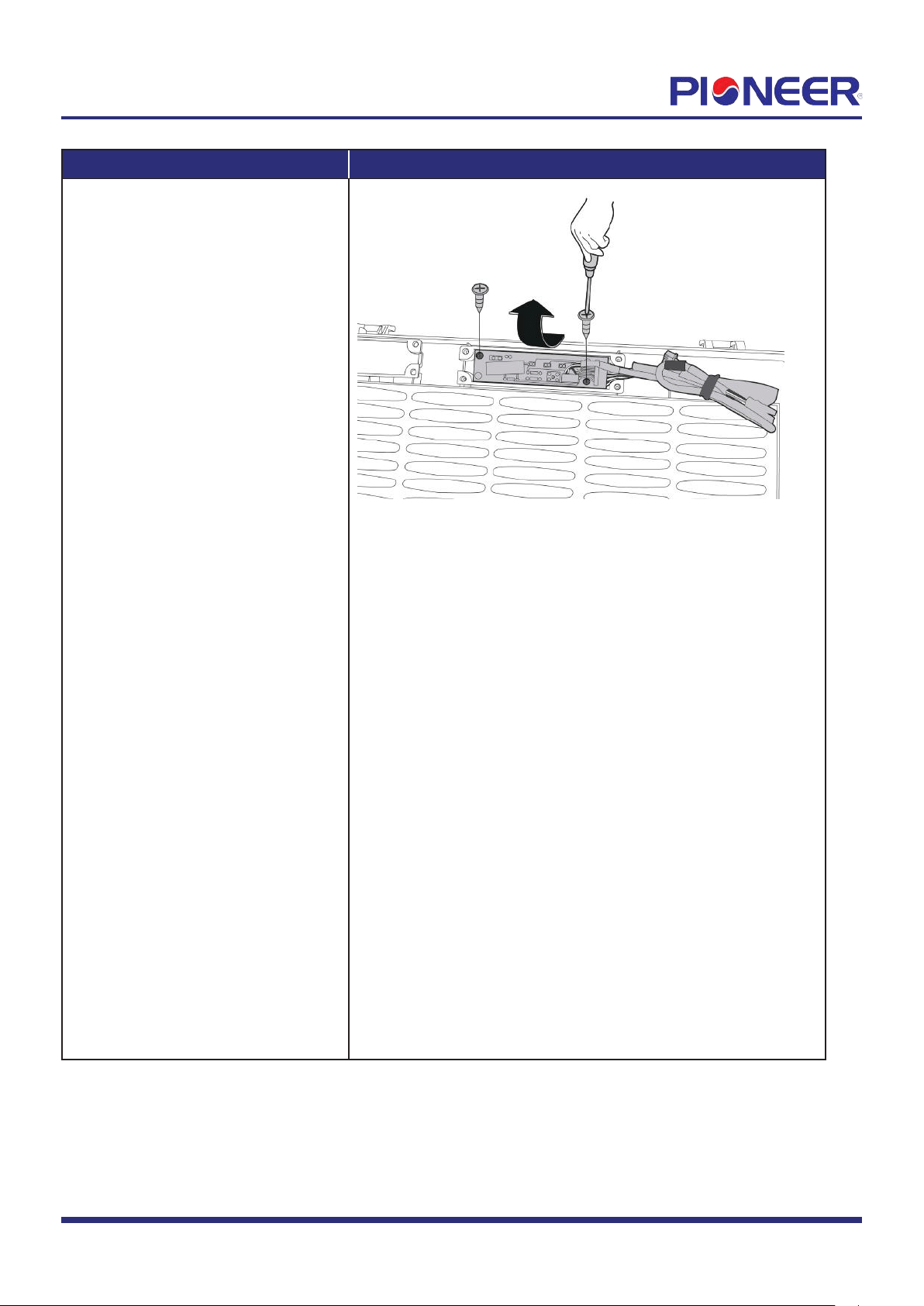
Pr
ocedure Illustration
5) Remove 2 screws of display
board and remove PCB. (see Figure
5).
Figure 5
Note: This section is for r
eference only. Actual unit appearance may vary.
Page
3
2. Electrical parts (Antistatic gloves must be worn.)
Note: Remove the front panel (refer to 1. Front Panel and display) before disassembling electrical parts.
Pr
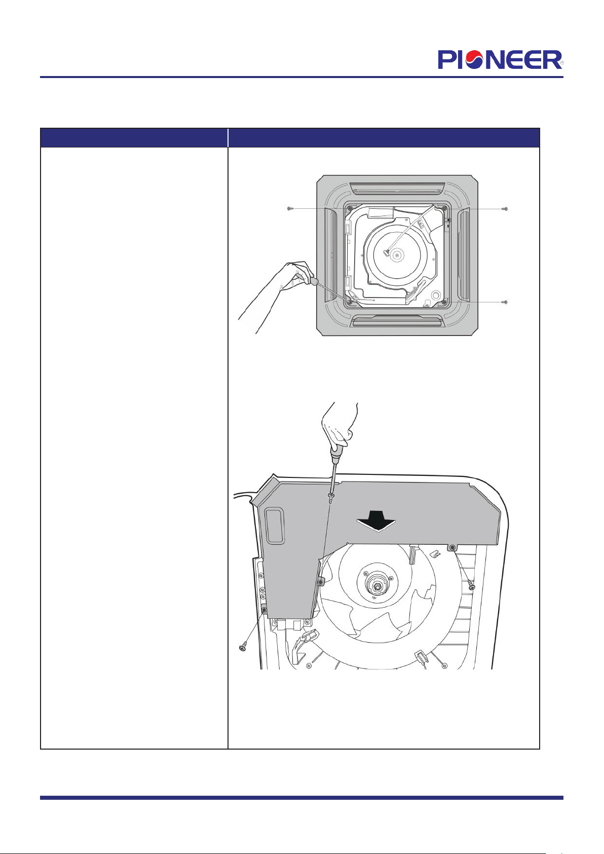
ocedure Illustration
1) Remove 4 screws of the
panel and pull up the panel.
(see Figure 6).
2) Remove 3 screws of electrical
cover (see Figure 7).
Figure 6
Figure 7
Note: This section is for r
eference only. Actual unit appearance may vary.
Page
4
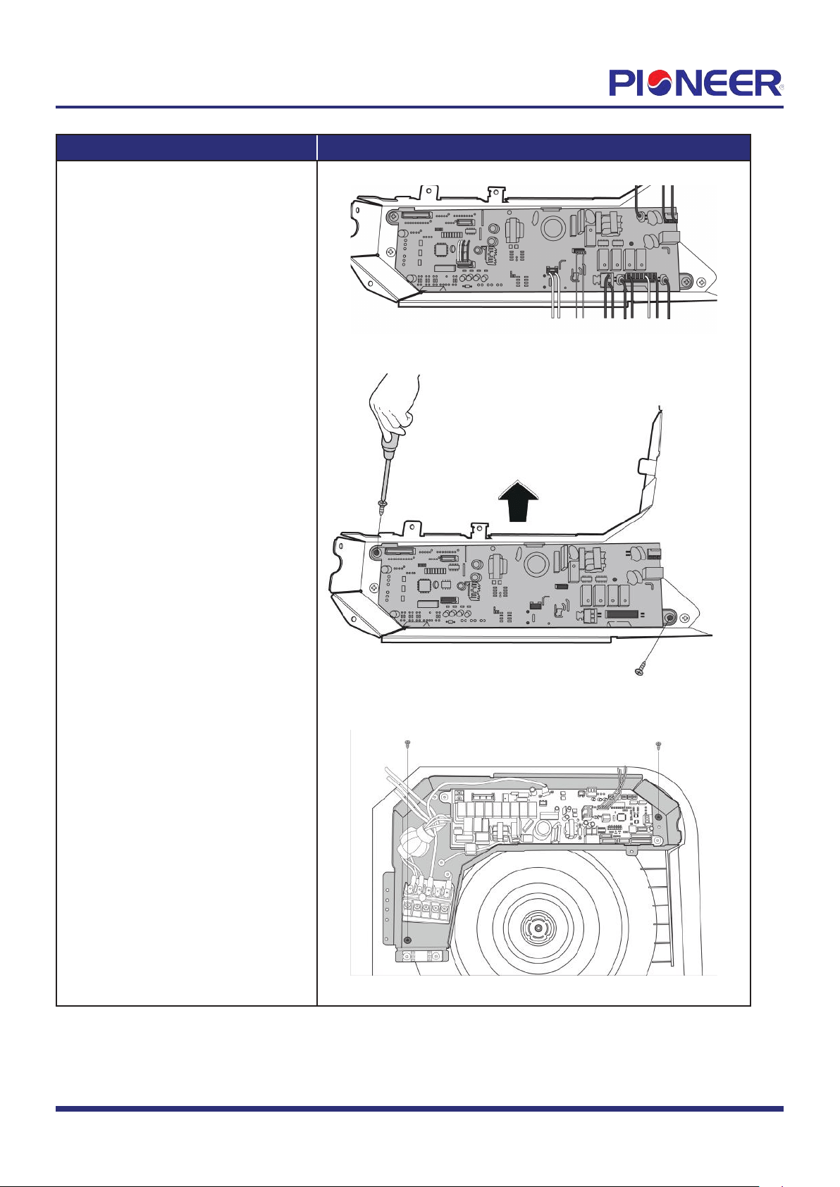
Pr
ocedure Illustration
3) Disconnect the connectors of
PCB (see Figure 8).
4) Remove 2 screws of main
control board and remove PCB (see
Figure 9).
5) Remove 2 screws of electronic
control box and remove electronic
control box (see Figure 10).
Figure 8
Figure 9
Figure 10
Note: This section is for r
eference only. Actual unit appearance may vary.
Page 5
3. Fan motor and Fan
Note: Remove the front panel and electrical parts (refer to 1 &2 ) before disassembling fan motor.
Pr
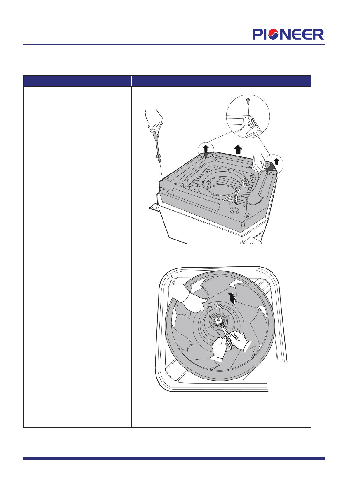
ocedure Illustration
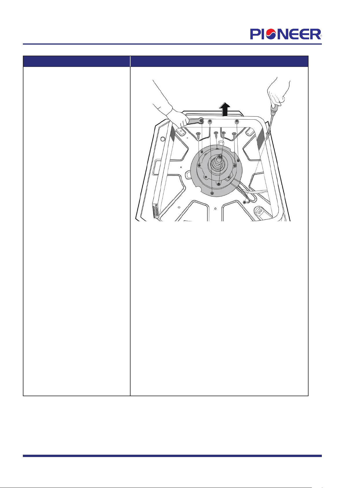
1) Remove 4 screws of water
collector then remove it (see Figure
11).
2) Remove the nut of the fan and
then pull out the fan (see Figure 12).
Figure 11
Figure 12
Note: This section is for r
eference only. Actual unit appearance may vary.
Page
6
Pr
ocedure Illustration
3) Remove the nuts and remove the
fan motor (see Figure 13).
Figure 13
Note: This section is for r
eference only. Actual unit appearance may vary.
Page 7
4. Water Pump
Note: Remove the fr
ont panel, electrical parts and water collector (refer to 1,2 &3) before disassembling water pump.
Pr
ocedure Illustration
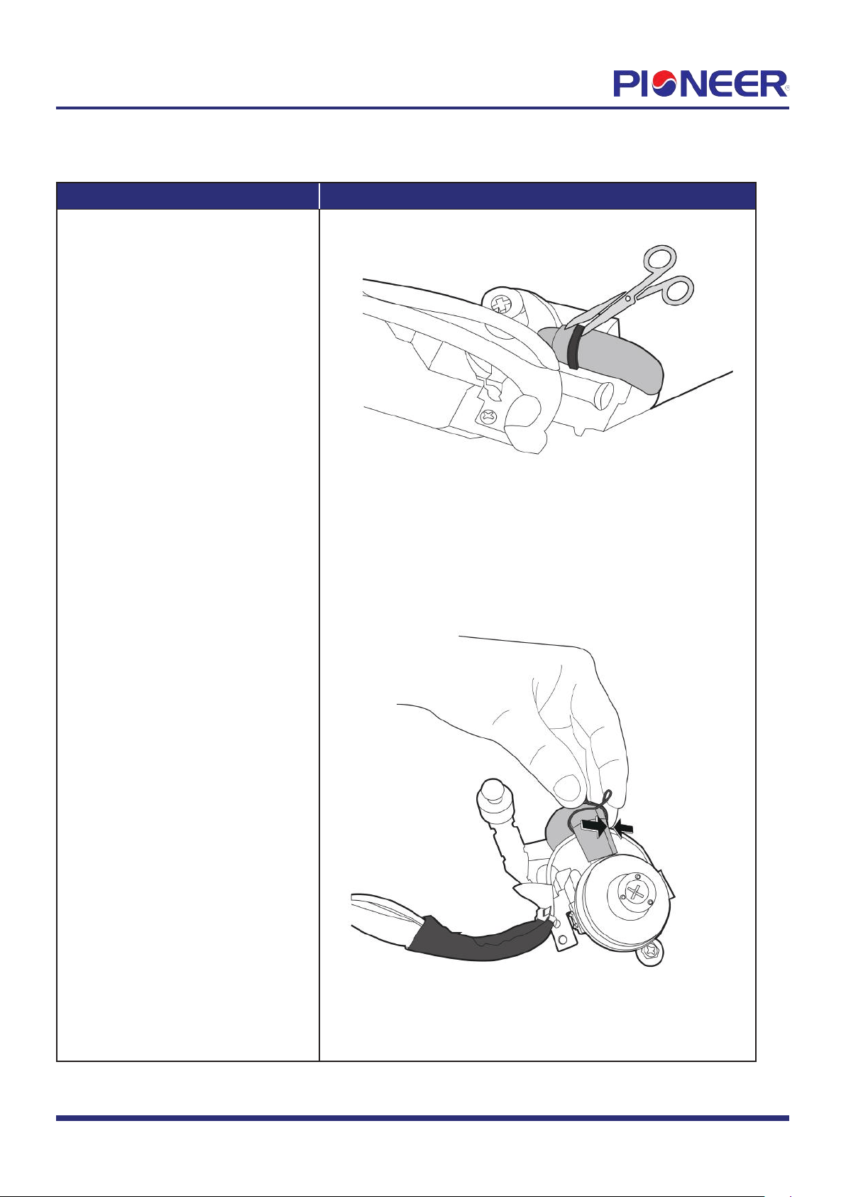
1) Take off the fasten belt of the water
pump (see Figure 14).
2) Pinch the metal wire in the direction
shown in the figure to release it.
(see Figure 15).
Figure 14
Figure 15
Note: This section is for r
eference only. Actual unit appearance may vary.
Page
8
Pr
ocedure Illustration
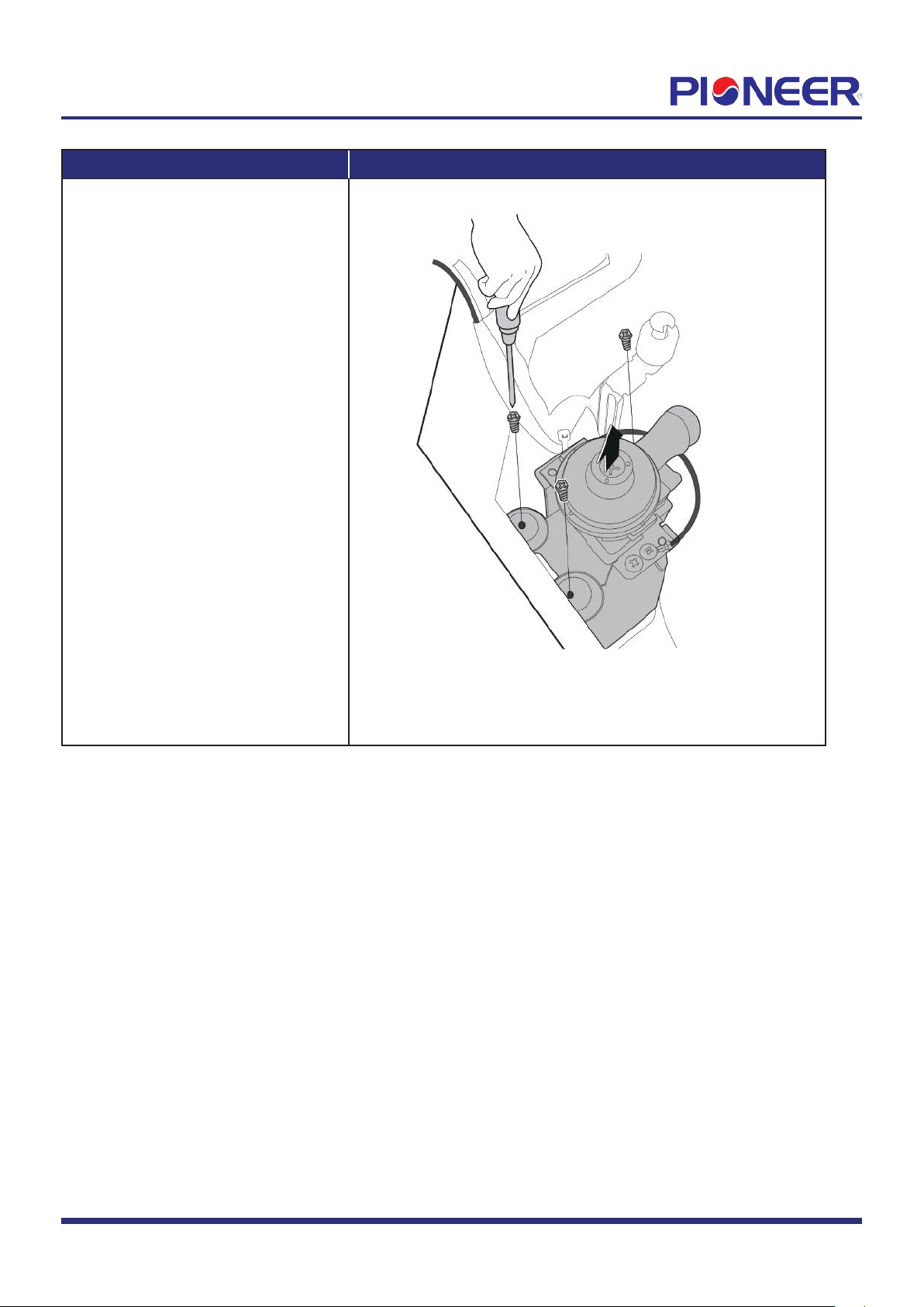
3) Remove 3 screws and then remove
the water pump (see Figure 16).
Figure 16
Page 9
5. Evaporator
Note: Remove the front panel, electrical parts and fan(refer to 1,2 &3) before disassembling evaporator.
Pr
ocedure Illustration
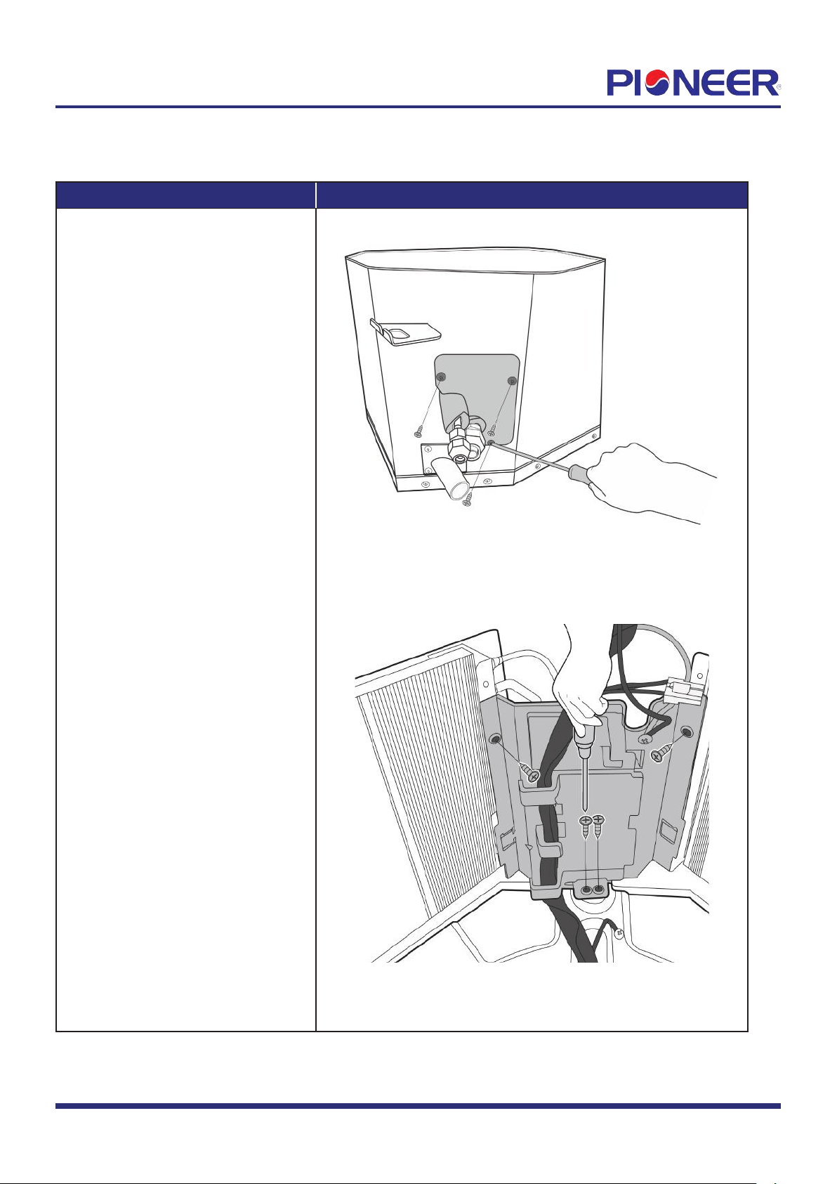
1) Remove 3 screws of pipe clamp
board assembly then remove it
(see Figure 17).
2) Remove 4 screws of evaporator
fixing board then remove it (see
Figure 18).
Figure 17
Figure 18
Note: This section is for r
eference only. Actual unit appearance may vary.
Page
10

Procedur
e Illustration
3) Remove 1 screw of evaporator
fixing hook and remove it (see Figure
19).
Figure 19
Note: This section is for refer
ence only. Actual unit appearance may vary.
Page 11