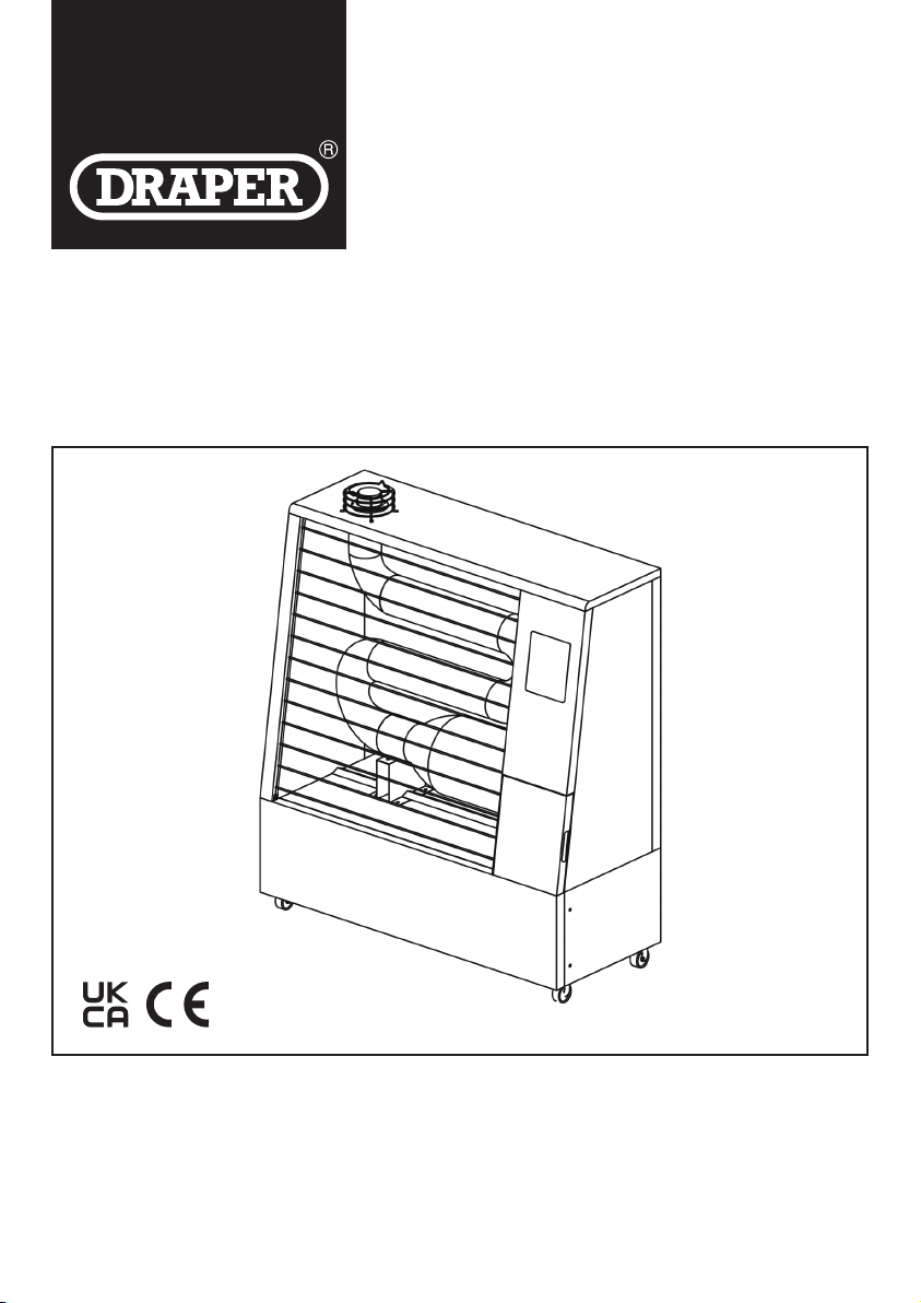
FAR INFRA-RED
DIESEL HEATER
06732, 06733 & 07108
These instructions accompanying the product are the original instructions. This document is part of the product, keep it
for the life of the product passing it on to any subsequent holder of the product. Read all these instructions before
assembling, operating or maintaining this product.
This manual has been compiled by Draper Tools describing the purpose for which the product has been designed, and
contains all the necessary information to ensure its correct and safe use. By following all the general safety instructions
contained in this manual, it will ensure both product and operator safety, together with longer life of the product itself.
AlI photographs and drawings in this manual are supplied by Draper Tools to help illustrate the operation of the product.
Whilst every effort has been made to ensure the accuracy of information contained in this manual, the Draper Tools
policy of continuous improvement determines the right to make modications without prior warning.
Please note that model number 06732 is illustrated throughout this instruction booklet.

– 2 –
1. TITLE PAGE
1.1 INTRODUCTION
USER MANUAL FOR: Far infra-red diesel heater
Stock Nos: 06732, 06733 & 07108
Part Nos: LMP510 & LMP530
1.2 REVISION HISTORY
Date rst published: June 2021.
As our user manuals are continually updated, users should make sure that they use
the very latest version.
Downloads are available from: http://drapertools.com/manuals
Draper Tools Limited
Hursley Road
Chandler’s Ford
Eastleigh
Hampshire
SO53 1YF
UK
Website: drapertools.com
Product help line: +44 (0) 23 8049 4344
General Fax: +44 (0) 23 8026 0784
1.3 UNDERSTANDING THIS MANUAL’S SAFETY CONTENT
WARNING! – Information that draws attention to the risk of injury or death.
CAUTION! – Information that draws attention to the risk of damage to the product or surroundings.
1.4 COPYRIGHT © NOTICE
Copyright © Draper Tools Limited.
Permission is granted to reproduce this publication for personal and educational use only.
Commercial copying, redistribution, hiring or lending is prohibited.
No part of this publication may be stored in a retrieval system or transmitted in any other form or
means without written permission from Draper Tools Limited.
In all cases this copyright notice must remain intact.

– 3 –
2. CONTENTS
2.1 CONTENTS
1. TITLE PAGE
1.1 INTRODUCTION ..................................................................................................................2
1.2 REVISION HISTORY ............................................................................................................2
1.3 UNDERSTANDING THIS MANUAL’S SAFETY CONTENT .................................................2
1.4 COPYRIGHT © NOTICE ......................................................................................................2
2. CONTENTS
2.1 CONTENTS ..........................................................................................................................3
3. WARRANTY
3.1 WARRANTY .........................................................................................................................4
4. INTRODUCTION
4.1 SCOPE .................................................................................................................................5
4.2 SPECIFICATION ..................................................................................................................5
4.3 HANDLING AND STORAGE ................................................................................................5
5. HEALTH AND SAFETY INFORMATION
5.1 GENERAL HEATER SAFETY WARNINGS ..........................................................................6
5.2 CONNECTION TO THE POWER SUPPLY ..........................................................................9
6. TECHNICAL DESCRIPTION
6.1 IDENTIFICATION ...............................................................................................................10
7. UNPACKING AND CHECKING
7.1 PACKAGING .......................................................................................................................11
8. FUELLING
8.1 FUELLING STEP ................................................................................................................12
9. OPERATING THE HEATER
9.1 SET-UP ...............................................................................................................................13
9.2 SELECT TEMPERATURE OR TIME CONTROL MODE ....................................................13
9.3 HOW TO BLEED FUEL LINES ...........................................................................................14
10. MAINTENANCE
10.1 DAILY CHECK-UP ............................................................................................................15
10.2 REGULAR INSPECTION .................................................................................................15
11. TIPS BEFORE INSTALLATION
12. WIRING
13. TROUBLESHOOTING
13.1 TROUBLESHOOTING GUIDE .........................................................................................18
14. EXPLANATION OF SYMBOLS
14.1 EXPLANATION OF SYMBOLS ........................................................................................19
15. DISPOSAL
15.1 DISPOSAL ........................................................................................................................19

– 4 –
3. WARRANTY
3.1 WARRANTY
Draper tools have been carefully tested and inspected before shipment and are guaranteed to be
free from defective materials and workmanship.
Should the tool develop a fault, please return the complete tool to your nearest distributor or
contact
Draper Tools Limited, Chandler’s Ford, Eastleigh, Hampshire, SO53 1YF. England.
Telephone Sales Desk: +44 (0) 23 8049 4333 or Product Help Line +44 (0) 23 8049 4344.
A proof of purchase must be provided with the tool.
If upon inspection it is found that the fault occurring is due to defective materials or workmanship,
repairs will be carried out free of charge. This warranty period covering parts/labour is 12 months
from the date of purchase except where tools are hired out when the warranty period is 90 days
from the date of purchase. This warranty does not apply to any consumable parts, any type of
battery or normal wear and tear, nor does it cover any damage caused by misuse, careless or
unsafe handling, alterations, accidents, or repairs attempted or made by any personnel other than
the authorised Draper warranty repair agent.
Note: If the tool is found not to be within the terms of warranty, repairs and carriage charges will
be quoted and made accordingly.
This warranty applies in lieu of any other warranty expressed or implied and variations of its terms
are not authorised.
Your Draper warranty is not effective unless you can produce upon request a dated receipt or
invoice to verify your proof of purchase within the warranty period.
Please note that this warranty is an additional benet and does not affect your statutory rights.
Draper Tools Limited.

– 5 –
4. INTRODUCTION
4.1 SCOPE
This heater is designed to heat large, semi-open areas by means of combustion of Diesel or
Kerosene fuel, and is electrically operated. Any other application is considered mis-use.
4.2 SPECIFICATION
STOCK NOS. ................................................................................................ 06732 / 06733 / 07108
PART NOS. .....................................................................DSH-FIR400 / DSH-FIR515 / DSH-FIR675
MOTOR:
RATED VOLTAGE ............................................................................................................... 230V
RATED FREQUENCY .........................................................................................................50HZ
RATED INPUT (IGNITION) .............................................................................. 60W / 70W / 70W
RATED INPUT (RUNNING) ............................................................................. 40W / 50W / 50W
HEAT OUTPUT..............................40,000BTU/11.6KW / 51,500BTU/15.1KW / 67,500BTU/19.8KW
FUEL .................................................................................................................DIESEL/KEROSENE
DIESEL CONSUMPTION ................................................. 0.9LTRS/HR / 1.2LTRS/HR / 1.7LTRS/HR
TANK CAPACITY ..........................................................................................25LTR / 30LTR / 45LTR
WEIGHT (NETT) ...............................................................................................40KG / 47KG / 58KG
DIMENSIONS ...............................710X320X1,110MM / 920X320X1,110MM / 1235X320X1,110MM
4.3 HANDLING AND STORAGE
– Care must be taken when handling this product.
• Dropping or letting this heater fall-over could also result in personal injury. This product is
not a toy and must be respected.
– Environmental conditions can have a detrimental effect on this product if neglected.
• Exposure to damp air can gradually corrode components.
• If the product is unprotected from dust and debris, components will become clogged.
• If not cleaned and maintained correctly or regularly, the machine will not perform at its best.

– 6 –
5. HEALTH AND SAFETY INFORMATION
5.1 GENERAL HEATER SAFETY WARNINGS
Warning!
Read all safety warnings and all instructions. Failure to follow the warnings and instructions
may result in electric shock, re and/or serious injury.
Save all warnings and instructions for future reference.
1) Work area safety
a) Keep work area clean and well lit. Cluttered or dark areas invite accidents.
b) Do not operate heaters in explosive atmospheres, such as in the presence of
ammable liquids, gases or dust. Heaters create sparks which may ignite the dust
or fumes.
c) Keep children and bystanders away while operating a heater. Distractions can cause
you to lose control.
2) Electrical safety
a) Heaters plugs must match the outlet. Never modify the plug in any way. Do not use
any adapter plugs with earthed (grounded) heaters. Unmodied plugs and matching
outlets will reduce risk of electric shock.
b) Avoid body contact with earthed or grounded surfaces such as pipes, radiators,
ranges and refrigerators. There is an increased risk of electric shock if your body is
earthed or grounded.
c) Do not expose heaters to rain or wet conditions. Water entering a heater will increase
the risk of electric shock.
d) Do not abuse the cord. Never use the cord for carrying, pulling or unplugging the
heater. Keep cord away from heat, oil, sharp edges or moving parts. Damaged or
entangled cords increase the risk of electric shock.
e) Do not operate heater outdoors.
f) Do not operate in damp or wet environments.
3) Personal safety
a) Stay alert, watch what you are doing and use common sense when operating a
heater. Do not use a heater while you are tired or under the inuence of drugs,
alcohol or medication. A moment of inattention while operating heaters may result in
serious personal injury.
b) Use personal protective equipment. Always wear eye protection. Protective equipment
such as dust mask, non-skid safety shoes, hard hat, or hearing protection used for
appropriate conditions will reduce personal injuries.
c) Prevent unintentional starting. Ensure the switch is in the off position before
connecting to power source.
d) Remove any adjusting key or wrench before turning the heater on. A wrench or a key
left attached to a rotating part of the heater may result in personal injury.
e) Dress properly. Do not wear loose clothing or jewellery. Keep your hair, clothing and
gloves away from moving parts. Loose clothes, jewellery or long hair can get sucked into
the in moving parts of the heater.

– 7 –
4) Heater use and care
DO NOT move the heater when it is in operation or when plugged into the mains supply.
Only move heater once it has cooled and it has been unplugged.
a) Use the correct heater for your application. The correct heater will do the job better and
safer at the rate for which it was designed.
b) Do not use the heater if the switch does not turn it on and off. Any heater that cannot
be controlled with the switch is dangerous and must be repaired.
c) Disconnect the plug from the power source before making any adjustments.
Such preventive safety measures reduce the risk of starting the heater accidentally.
d) Store idle heater out of the reach of children and do not allow persons unfamiliar
with the heater or these instructions to operate the power tool. Heaters are dangerous
in the hands of untrained users.
e) Maintain heaters. Check for misalignment or binding of moving parts, breakage of
parts and any other condition that may affect the heaters operation. If damaged, have
the heater repaired before use. Many accidents are caused by poorly maintained heaters.
f) Use the heater, in accordance with these instructions, taking into account the
working conditions and the work to be performed. Use of the heater for operations
different from those intended could result in a hazardous situation.
5) Service
a) Have your heater serviced by a qualied repair person using only identical
replacement parts. This will ensure that the safety of the heater is maintained.
Warning!
Diesel fuel is carcinogenic. Take care when transporting, refuelling and storage of diesel fuel.
Always clean up fuel spills with regard to local legislative requirements.
Warning!
Before using this heater please read this OPERATING INSTRUCTION very carefully. This USER’S
MANUAL has been designed to instruct you as to the proper manner in which to assemble,
maintain, store, and most importantly, how to operate the heater in a safe and efcient manner.
Danger!
Improper use of this heater can result in serious injury or death from burns, re, explosion,
electrical shock, and/or carbon monoxide poisoning.
Warning!
Risk of Burns/Fire/Explosion!
– NEVER use fuels such as petrol, benzene, paint thinners, or other oil compounds in this
heater (RISK OF FIRE OR EXPLOSION)
– NEVER use this heater where ammable vapours may be present
– NEVER rell the heater’s fuel tank while heater is operating or still hot. This heater is
EXTREMELY HOT while in operation
– Keep all combustible materials away from this heater.
Use only diesel or kerosene fuel according to EN 267. For details please refer to your fuel supplier
or contact your dealer.

– 8 –
Warning!
Never leave the heater unattended while burning!
Warning!
Risk of Indoor Air Pollution!
– Use this heater only in well ventilated areas!
– Provide at least a three square foot (2,800 sq cm) opening of outside air for every
25,000Kcal/hr of heater rating.
– People with breathing problems should consult a physician before using the heater.
– Carbon Monoxide Poisoning: Early signs of carbon monoxide poisoning resemble u-like
symptoms such as headaches, dizziness, and/or nausea. If you have these symptoms,
your heater may not be working properly.
– Get fresh air at once! Have the heater serviced. Some people are more affected by carbon
monoxide than others. These include pregnant women, those with heart or lung problems,
anaemia, or those under the inuence of alcohol, or at high altitudes.
– If using in semi-enclosed environments – use optional ue kit – 07399.
Warning!
Installation of the heater & ue kit must only be undertaken by a suitably qualied person.
Warning!
Risk of Electric Shock!
Use only the electrical power (voltage and frequency) specied on the model plate of the heater.
Use only a three-prong, grounded outlet and extension cord.
– ALWAYS install the heater so that it is not directly exposed to water spray, rain, dripping water,
or wind.
– ALWAYS unplug the heater when not in use.
Minimum Clearances
Outlet – 8 feet (250cm).
Sides, Top and Rear – 4 feet (125cm).
– NEVER block air inlet (rear) or air outlet (front) of heater.
– NEVER move or handle heater while still hot.
– NEVER transport heater with fuel in its tank.
– When used with optional thermostat or if equipped with a thermostat, the heater may start at
any time.
– ALWAYS locate heater on a stable and level surface.
– ALWAYS keep children and animals away from heater.
– Use Diesel or 1-K kerosene in this heater. #1 fuel oil is a suitable substitute.
– Bulk fuel storage should be a minimum of 25ft from heaters, torches, portable generators,
or other sources of ignition. All fuel storage should be in accordance with National, state,
or local authorities.
5. HEALTH AND SAFETY INFORMATION
– 9 –
5.2 CONNECTION TO THE POWER SUPPLY
Caution: Risk of electric shock. Do not open.
This appliance is supplied with an approved plug and cable for your safety. The value of the fuse
tted is marked on the pin face of the plug. Should the fuse need replacing, ensure the substitute
is of the correct rating, approved to BS1362 and ASTA or BS Kite marked.
ASTA
BSI
The fuse cover is removable with a small plain slot screwdriver. Ensure the fuse cover is replaced
before attempting to connect the plug to an electrical outlet. If the cover is missing, a replacement
must be obtained or the plug replaced with a suitable type.
If a replacement plug is to be tted this must be carried out by a qualied electrician.
The damaged or incomplete plug, when cut from the cable shall be disabled to prevent connection
to a live electrical outlet.
This appliance is Class I † and is designed for connection to a power supply matching that detailed
on the rating label and compatible with the plug tted.
If an extension lead is required, use an approved and compatible lead rated for this appliance.
Follow all the instructions supplied with the extension lead.
†Earthed: This product requires an earth connection to protect against electric shock from
accessible conductive parts in the event of a failure of the basic insulation.
IMPORTANT
If using an extension lead, follow the instructions that came with your lead regarding
maximum load while cable is wound. If in doubt, ensure that the entire cable is unwound.
Using a coiled extension lead will generate heat which could melt the lead and cause a re.
– 10 –
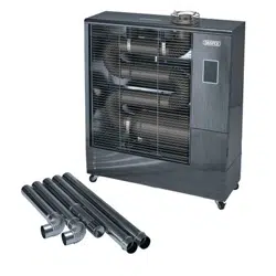
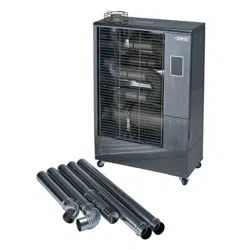
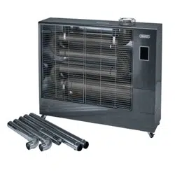
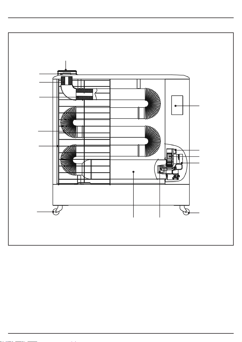
6. TECHNICAL DESCRIPTION
6.1 IDENTIFICATION
(1) Exhaust
(2) Heater control plate
(3) Air outlet
(4) Fan
(5) Motor
(6) Caster
(7) Nozzle
(8) Combustion chamber
(9) Caster
(10) Front safety guard
(11) Far infra-red heater tube
(12) Silencer
(13) Silencer
(14) Exhaust –
connection for optional
ue kit 07399
(4)
(2)
(3)
(5)
(6)
(1)
(7)(8)
(10)
(11)
(9)
(12)
(13)
(14)
– 11 –
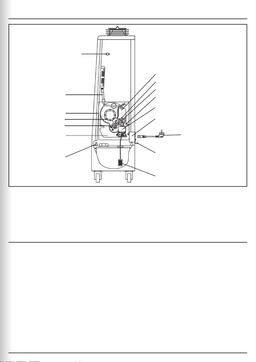
7.1 PACKAGING
Carefully remove the product from the packaging and examine it for any sign of damage that may
have happened during shipping. Lay the contents out and check them against the parts shown
below. If any part is damaged or missing, please contact the Draper Help Line (the telephone
number appears on the Title page) and do not attempt to use the product.
The packaging material should be retained at least during the warranty period, in case the
machine needs to be returned for repair.
Warning!
– Some of the packaging materials used may be harmful to children. Do not leave any of these
materials in the reach of children.
– If any of the packaging is to be thrown away, make sure they are disposed of correctly,
according to local regulations.
– You must remove all protective transit packaging from the machine before rst use.
(15) Thermostat
(16) Ignitor
(17) Fuel pipes
(18) Photocell
(19) Solenoid valves
(20) Pump
(21) Filter
(22) Power cord
(23) Thermistor
(24) Filter
(25) Tipover switch
(26) Pump
(27) Burner
(28) Control panel
connector
7. UNPACKING AND CHECKING
(15)
(17)
(16)
(18)
(19)
(20)
(21)
(23)
(24)
(25)
(26)
(19)
(17)
(27)
(28)
(22)
– 12 –
8. FUELLING
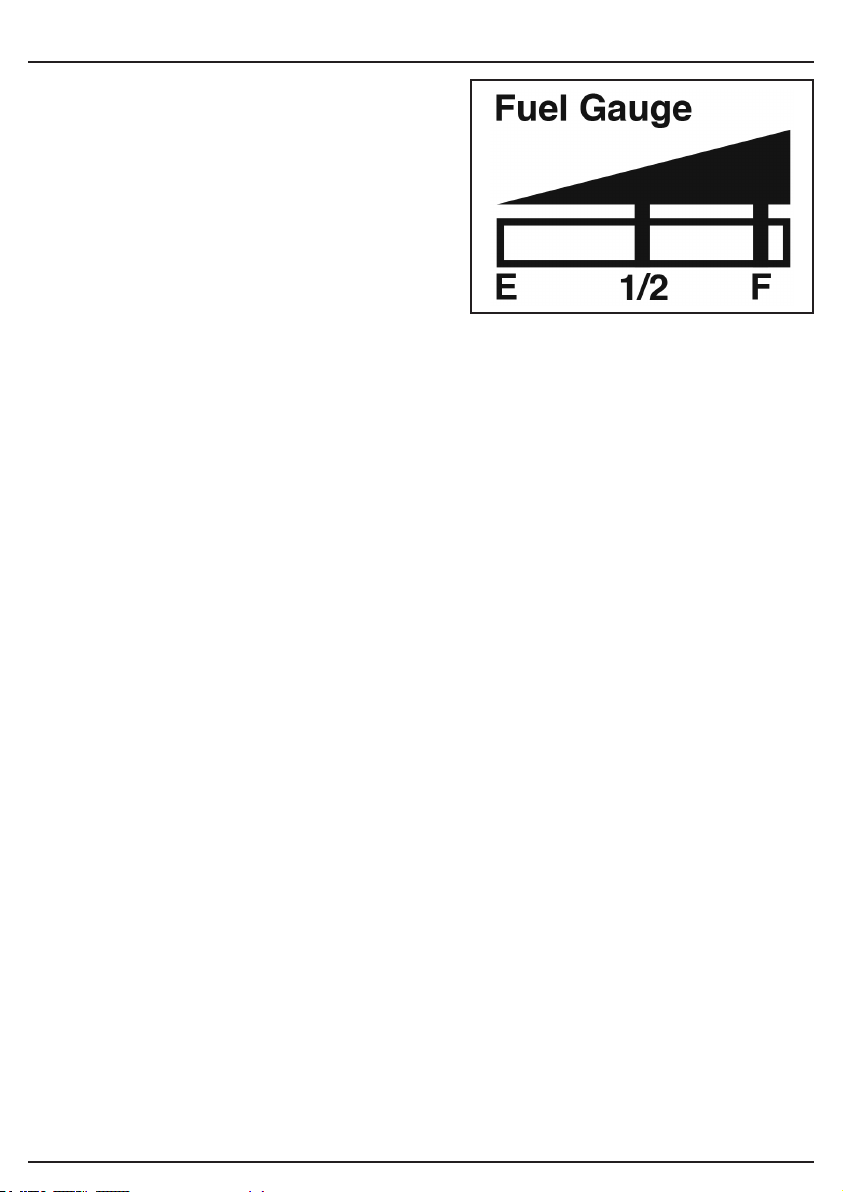
8.1 FUELLING STEP – FIG. 1
Open the fuel inlet cap for the fuel tank.
Carefully put in the fuel, trying not to spill the fuel.
- At this time, ll until the fuel gauge reaches ‘F’.
Tightly close the fuel cap.
Check if fuel has leaked around fuel tank or each
part of the heater. If it has leaked, clean it.
Warning!
During production and assembly some production
substance will be on the heater tubes – these will
simply & harmlessly burn-off during the rst 1-2
hours of use. After this period of use the heater
should not emit unusual smells during use.
Only refuel on at & level ground.
Never refuel the heater when it is operation.
The heater must be switched off & cooled
BEFORE any attempt is made to re-fuel it.
Do not over-fuel the heater, only use enough fuel
to bring the fuel gauge up to the full mark. If you
do spill fuel you MUST ensure that it is fully
cleaned off of the heater and the surrounding
area before use.
Do not use “old” or “second-hand” fuel or any fuel
other than clean, fresh, new Disel or Kerosene.
Using any other type of fuel will invalidate the
warranty and could cause explosion or re.
Do not put low-quality fuel. Always use high-quality
and clean fuel. It may cause breakdown.
FIG. 1
– 13 –
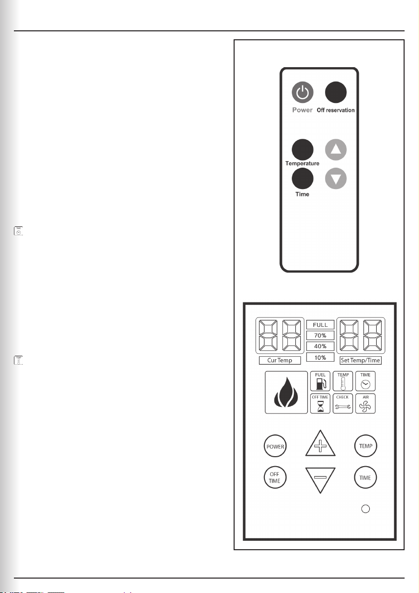
9.1 SET-UP
Put the plug into the outlet.
The current temp. and setting temp. both are
displayed during operaton.
In order to be operated, the setting temperature
should be higher than current temperature.
Power On
Important!
For rst use you may need to bleed the fuel pump
lines – this is a simple operation and should only
be required for the initial start or when the machine
has not been used for some time – please see
section 9.3 below.
9.2 SELECT TEMPERATURE OR TIME
CONTROL MODE – FIG. 2
Time control lamp displays when selected.
Every 30min. Operation and 30Min Pause
The repitition time can be set from 5 min. to 25
min. (Only every 5 minutes.)
Repetition time 15 means, every 15min. Operaton
and 15min. Pause
Every 1 min. is shortened as time goes on
Time is shortened every 1 min. when the set time
is 10 min. (10, 9, 8…….1)
Time is shortened every 1 min. when the set time
is 20 min. (20, 19, 18…….1)
Temperature control lamp displays when
selected.
You can set the desired temperature between
‘0~40°C’ by pressing ‘+/-’ button.
When the setting temp. is higher than current
temp. it starts operation, and the setting temp. is
less than current temp. the operation is stop
FIG. 2
9. OPERATING THE HEATER

– 14 –
To select whether off timer mode is operated or not. At that time, off timer lamp displays)
Set Temp. / Time indicates the reserved time.
By pushing ‘+/_’ button, time is changed every an hour. It can be set in 24 hours totally.
Set Temp. or Set Time indicates again after 2 seconds
Remain time indicates by ickering 10 times every 5 min.
Off Timer is indicated when set the off timer for 5 hours. (5, 4, 3hr …….55, 50…5min)
During the operation if you push Off Timer button, Off timer function is cancelled.
Low fuel warning light
Heater will turn off in one minute. Once heater has cooled, switch off and refuel as necessary.
Service light
If service light is showing – refer to Troubleshooting Guide – 13.1.
9.3 HOW TO BLEED FUEL LINES
If you notice that the fuel pump is noisy and the heater is not igniting it is most likely that air has
entered the fuel pipes due to the heater being operated without fuel.
It is simple to bleed the air out of the fuel line.
Simply open the access cover on the front of the heater and remove the rubber bung to expose
the fuel bleed screw.
Release the bleed screw anti-clockwise for 2-3 turns.
press the on button to operate the pump unit and after around 10 seconds you will see the air
bleed out of the fuel line.
Tighten the screw and operate the heater as normal.
Depending on how much air has been sucked into the heater, you may need to bleed the fuel line
in this manner up to 4 times.
9. OPERATING THE HEATER

– 15 –
10. MAINTENANCE
10.1 DAILY CHECK-UP
Warning!
Check-up and cleaning must be done after stopping ‘combustion’ of the heater.
Check if fuel leaks from any place near the fuel tank.
Check if combustion chamber or heating tube is corroded and damaged.
If heat-reecting board is dusty, clean it.
Check if the heater makes soot from the exhaust pipe.
Burner is adjusted to be suitable for function of the heater. If there are no user serviceable parts on
this heater – all service functions must be carried out by a suitably qualied professional.
Warning!
Cleaning the heater should be done after unplugging the cable and when it is completely cooled
down. It should be cleaned with a damp cloth and then dried. NEVER pour water on or use spray
detergents or cleaners on or around this heater.
10.2 REGULAR INSPECTION
Regular Inspection
Combustion furnace and heating tube (heat exchanger): once a year, check for soot and then
clean it as required.
Combustion furnace and reection board: once a year, check for corrosion and pollution and then
clean it (when it is corroded too much, exchange it).
Fuel lter (inside the tank): once a year, check for pollition with naked eyes and then exchange it.
– 16 –
11. TIPS BEFORE INSTALLATION
Warning!
ONLY use the heater on a solid at surface that is noncombustible (concrete etc). You MUST NOT
use the heater in a non-level surface, as this will affect the combustion efciency and operation.
You MUST have suitable space around the heater during its operation – minimum of 1.5 metres on
either side, the front and the top and at least 10cm from the back wall.
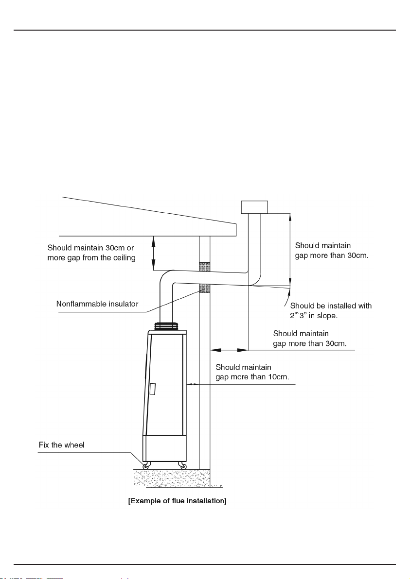
If you are using the heater indoors, we would strongly recommend the Draper 07399 ue kit to
ensure the exhaust fumes are routed out of the building safely.
Below is an example of a ue kit attached to the heater – but any ue use MUST be installed and
tested by a suitably qualied professional to ensure safe operation of the heater.
– 17 –
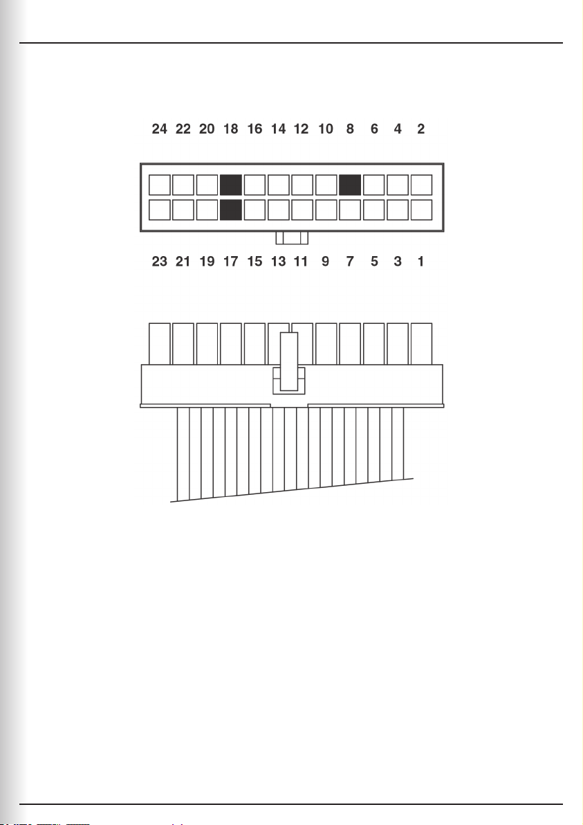
12. WIRING
1 + 3 Thermostat
4 F.G.
2 + 6 Power plug
8 N
5 + 7 Motor
5 + 11 Pump
5 + 13 Ignitor
9 + 10 Sol. valve
12 + 14 Blower fan
15 + 16 Tip over S/W
17 + 18 N
19 + 20 Oil gauge
21 + 22 Photo cell
23 + 24 Thermistor

– 18 –
13. TROUBLESHOOTING
13.1 TROUBLESHOOTING GUIDE
Problem Possible Cause Remedy
E1: Ignition failure Heater does not ignite Out of fuel, rell with correct
fuel
Fuel pipe is air-locked, bleed
fuel pipe as per manual
Photocell is dirty, clean
photocell as per manual
E3: Temperature sensor Temperature sensor is not
functioning
Check temperature sensor
connection / replace
E4: Thermal overload Overload sensor fault Clean & test sensor
connection / replace
E5: Tilt switch activation Heater has been moved while
operational
Ensure heater is stable
Check sensor connection
E6: No fuel Fuel has been used Rell with clean, fresh Diesel
/ Kerosene as per instructions
Hi Thermostat measuring above
50°C
Check thermostat sensor
operation
All the lamps in front control
panel are turned off
Power failure
Power cable is unplugged
Fuse is disconnected
Connect to power
Change the fuse
The heater turns on and off
regularly
Operation setting is selected
as “Time”
Select “Temperature”
Flow-meter does not work but
the heater operates
Flow-meter is disconnected Connect the line
Smoky smell is made during
initial operation
The smell is made as the
manufacturing contaminants
burn off
No smell will be made 1-2
hours later
Fuel smell is too strong As the heater turns off after
the operation, it might have
some smell
Fuel is leaked during
refuelling
Operate more than 15
minutes
Clean out leaked fuel
Internal temperature displays
higher than normal
Check for location of
temperature sensor at the
back of the heater (If sensor
is placed inside the heater)
Fix the sensor in the right
place
– 19 –
14. EXPLANATION OF SYMBOLS
14.1 EXPLANATION OF SYMBOLS
WEEE – Waste Electrical &
Electronic Equipment.
Do not dispose of Waste Electrical & Electronic
Equipment in with domestic rubbish.
15. DISPOSAL
15.1 DISPOSAL
– At the end of the machine’s working life, or when it can no longer be repaired, ensure that it is
disposed of according to national regulations.
– Contact your local authority for details of collection schemes in your area.
In all circumstances:
• Do not dispose of power tools with domestic waste.
• Do not incinerate.
• Do not dispose of WEEE* as unsorted municipal waste.
* Waste Electrical & Electronic Equipment.

CONTACTS
YOUR DRAPER STOCKIST
Draper Tools Limited, Hursley Road,
Chandler’s Ford, Eastleigh, Hampshire. SO53 1YF. U.K.
Help line: (023) 8049 4344
Sales desk: (023) 8049 4333
Internet: drapertools.com
E-mail: [email protected]
General enquiries: (023) 8026 6355
Service/Warranty Repair Agent:
For aftersales servicing or warranty repairs, please contact the
Draper Tools help line for details of an agent in your local area.
©Published by Draper Tools Limited.
No part of this publication may be reproduced, stored in a retrieval system or transmitted in any form or by any means,
electronic, mechanical photocopying, recording or otherwise without prior permission in writing from Draper Tools Ltd.
PJTL0621