OWNER’S GUIDE & SERVICE MANUAL
MARVEL UNDERCOUNTER REFRIGERATION
Model: MLCR215-IS01B
WELCOME
Welcome to the Marvel Experience!
Thank you for choosing our quality American-built product
to add to your home. We are thrilled to welcome you to
our growing community of Marvel owners, who trust in our
products and our support.
The information in this guide is intended to help you install
and maintain your new Marvel undercounter model to pro-
tect and prolong its lifetime. We encourage you to contact
our Technical Support team at (616) 754-5601 with any
questions.
Got a Marvelous Design?
We would love to see how your Marvel product looks in
its new home. Send us photos at marketing@marvelre-
frigeration.com, and we might feature your Marvel home
design on our website and social media!
Warranty Registration
It is important you send in your warranty registration card
immediately after taking delivery of your appliance or you
can register online at www.marvelrefrigeration.com.
The following information will be
required when registering your
appliance:
Service Number
Serial Number
Date of Purchase
Dealer’s name and address
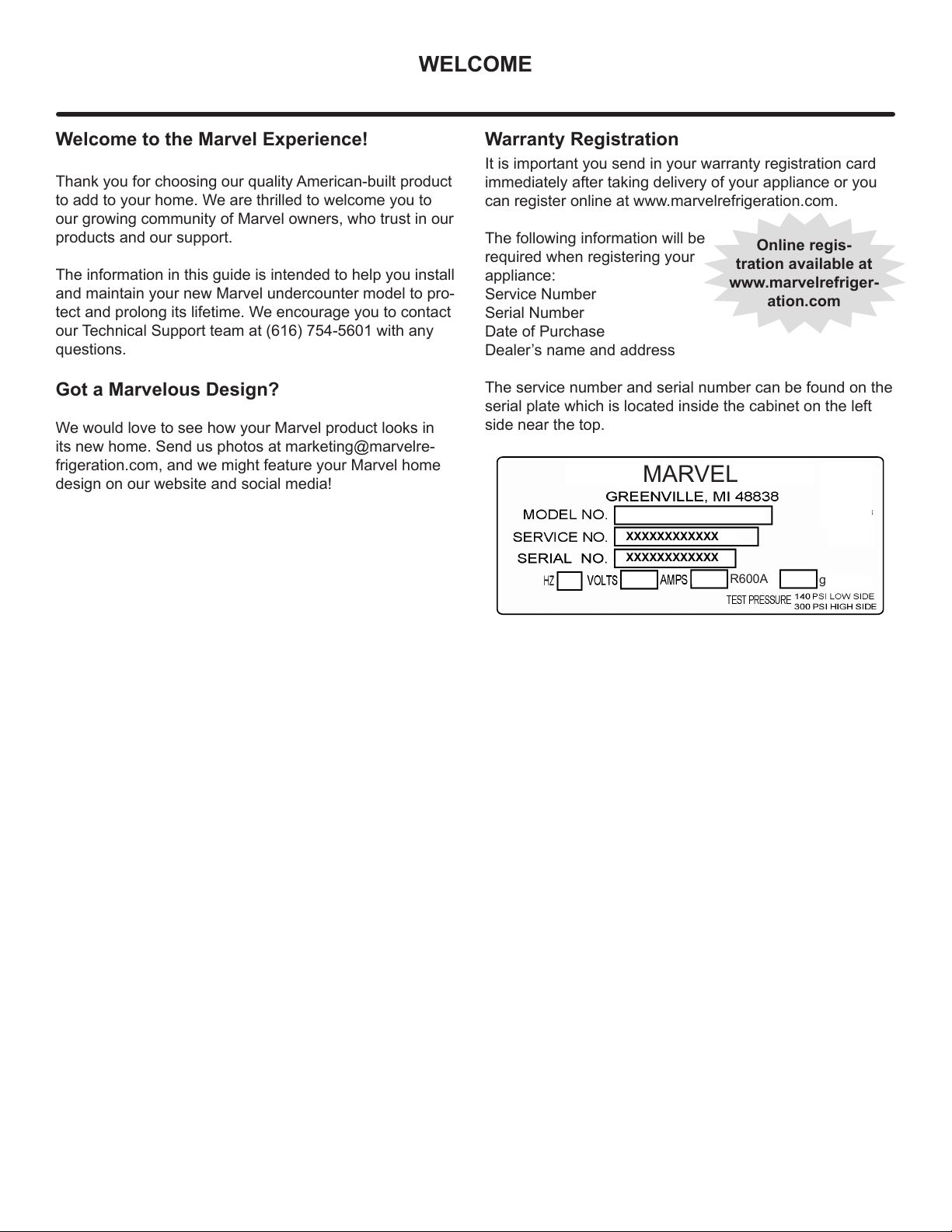
The service number and serial number can be found on the
serial plate which is located inside the cabinet on the left
side near the top.
Online regis-
tration available at
www.marvelrefriger-
ation.com
XXXXXXXXXXXX
XXXXXXXXXXXX
MARVEL
g
R600A

TABLE OF CONTENTS
Tip: Click on any section below to jump directly there
Safety
Important Safety Instructions
Installation
Unpacking Your Appliance
Electrical
Cutout & Product Dimensions
Side-by-Side & Stacking Installations
Installing the anti-tip device
Door Reversal
Integrated Panel Dimensions
Integrated Panel Installation
Installing The Water Supply
Maintenance
Care and Cleaning
Extended Non-Use
Operating Instructions
Ice Maker Operation
Service
Obtaining Service
Wire Diagram
Product Liability
Warranty Claims
Ordering Replacement Parts
R600a Specifications
System Diagnosis Guide
Defrost
Replace Ice Maker
Warranty
3
IMPORTANT SAFETY INSTRUCTIONSIMPORTANT SAFETY INSTRUCTIONS
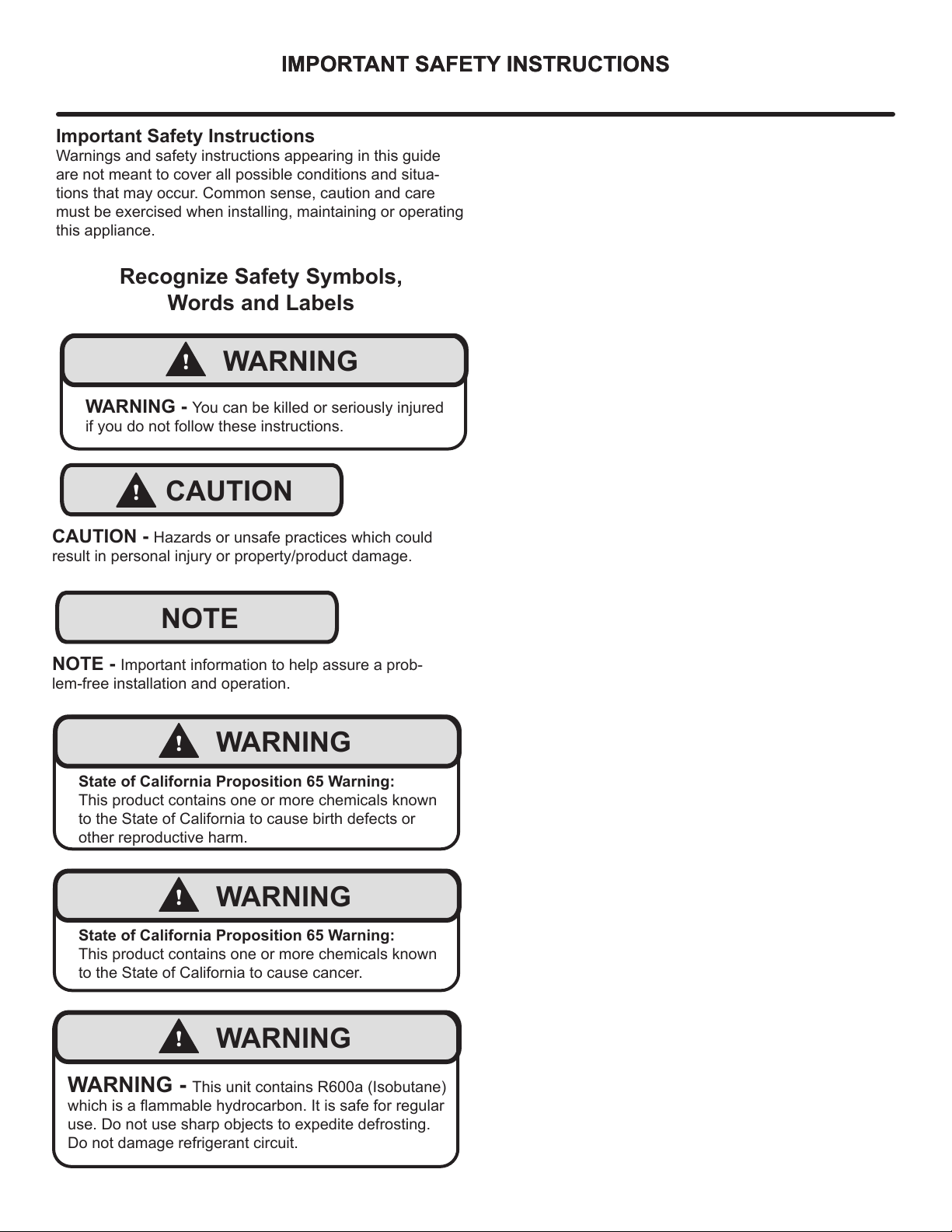
Important Safety Instructions
Warnings and safety instructions appearing in this guide
are not meant to cover all possible conditions and situa-
tions that may occur. Common sense, caution and care
must be exercised when installing, maintaining or operating
this appliance.
Recognize Safety Symbols,
Words and Labels
NOTE
!
CAUTION
CAUTION - Hazards or unsafe practices which could
result in personal injury or property/product damage.
NOTE - Important information to help assure a prob-
lem-free installation and operation.
!
WARNING
WARNING - You can be killed or seriously injured
if you do not follow these instructions.
!
WARNING
State of California Proposition 65 Warning:
This product contains one or more chemicals known
to the State of California to cause cancer.
!
WARNING
State of California Proposition 65 Warning:
This product contains one or more chemicals known
to the State of California to cause birth defects or
other reproductive harm.
!
WARNING
WARNING - This unit contains R600a (Isobutane)
which is a fl ammable hydrocarbon. It is safe for regular
use. Do not use sharp objects to expedite defrosting.
Do not damage refrigerant circuit.
4
UNPACKING YOUR APPLIANCE
!
WARNING
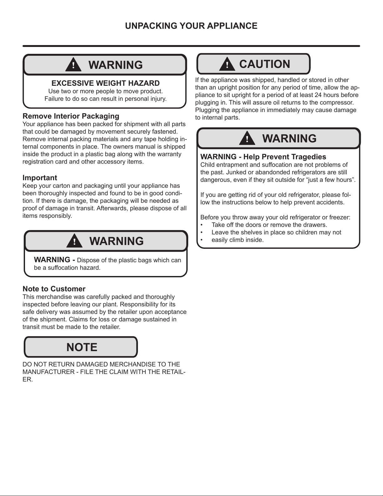
EXCESSIVE WEIGHT HAZARD
Use two or more people to move product.
Failure to do so can result in personal injury.
Remove Interior Packaging
Your appliance has been packed for shipment with all parts
that could be damaged by movement securely fastened.
Remove internal packing materials and any tape holding in-
ternal components in place. The owners manual is shipped
inside the product in a plastic bag along with the warranty
registration card and other accessory items.
Important
Keep your carton and packaging until your appliance has
been thoroughly inspected and found to be in good condi-
tion. If there is damage, the packaging will be needed as
proof of damage in transit. Afterwards, please dispose of all
items responsibly.
Note to Customer
This merchandise was carefully packed and thoroughly
inspected before leaving our plant. Responsibility for its
safe delivery was assumed by the retailer upon acceptance
of the shipment. Claims for loss or damage sustained in
transit must be made to the retailer.
DO NOT RETURN DAMAGED MERCHANDISE TO THE
MANUFACTURER - FILE THE CLAIM WITH THE RETAIL-
ER.
NOTE
!
WARNING
WARNING - Dispose of the plastic bags which can
be a suff ocation hazard.
!
CAUTION
!
WARNING
WARNING - Help Prevent Tragedies
Child entrapment and suff ocation are not problems of
the past. Junked or abandonded refrigerators are still
dangerous, even if they sit outside for “just a few hours”.
If you are getting rid of your old refrigerator, please fol-
low the instructions below to help prevent accidents.
Before you throw away your old refrigerator or freezer:
• Take off the doors or remove the drawers.
• Leave the shelves in place so children may not
• easily climb inside.
If the appliance was shipped, handled or stored in other
than an upright position for any period of time, allow the ap-
pliance to sit upright for a period of at least 24 hours before
plugging in. This will assure oil returns to the compressor.
Plugging the appliance in immediately may cause damage
to internal parts.
5
ELECTRICAL
NOTE
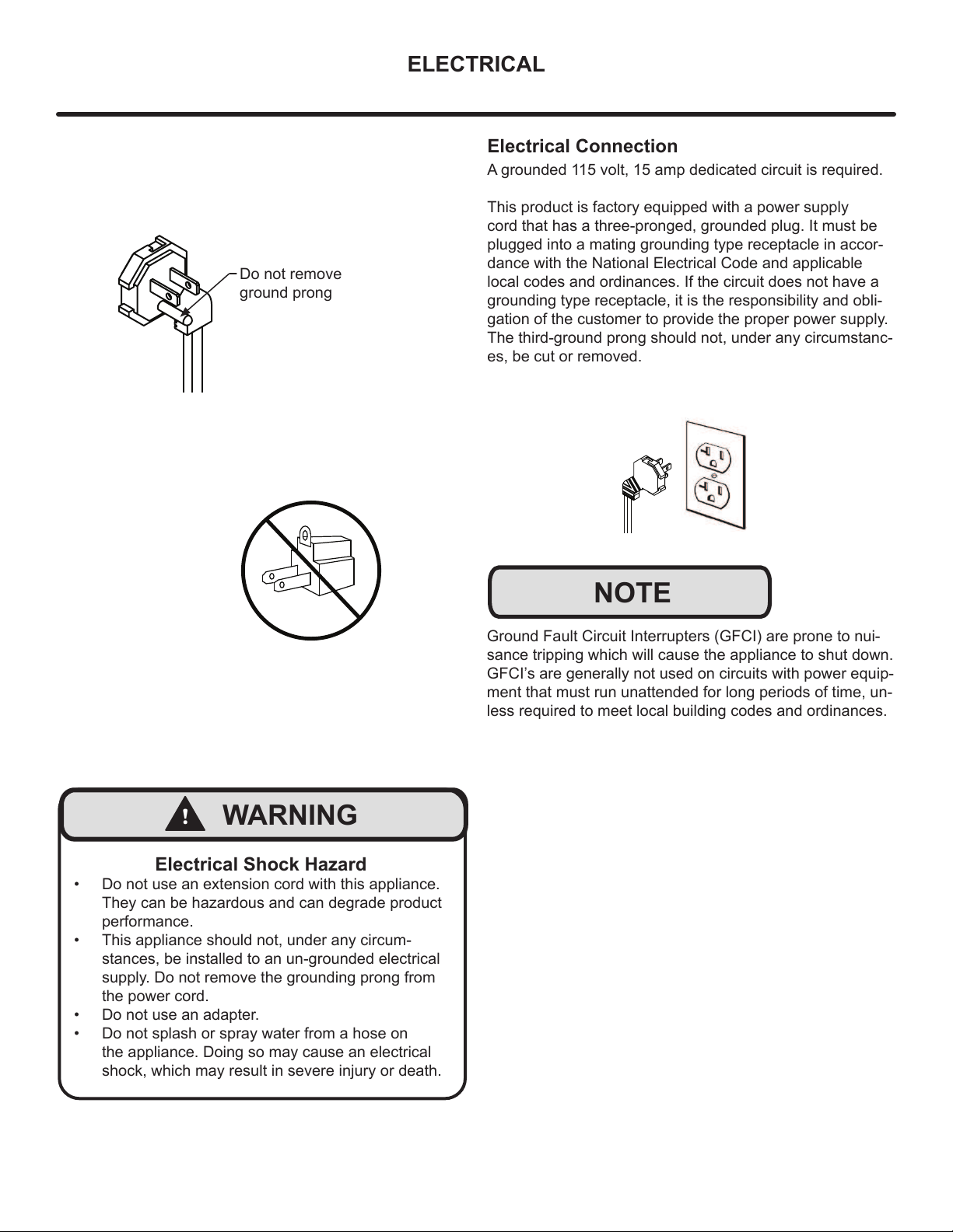
Electrical Shock Hazard
• Do not use an extension cord with this appliance.
They can be hazardous and can degrade product
performance.
• This appliance should not, under any circum-
stances, be installed to an un-grounded electrical
supply. Do not remove the grounding prong from
the power cord.
• Do not use an adapter.
• Do not splash or spray water from a hose on
the appliance. Doing so may cause an electrical
shock, which may result in severe injury or death.
!
WARNING
Ground Fault Circuit Interrupters (GFCI) are prone to nui-
sance tripping which will cause the appliance to shut down.
GFCI’s are generally not used on circuits with power equip-
ment that must run unattended for long periods of time, un-
less required to meet local building codes and ordinances.
Electrical Connection
A grounded 115 volt, 15 amp dedicated circuit is required.
This product is factory equipped with a power supply
cord that has a three-pronged, grounded plug. It must be
plugged into a mating grounding type receptacle in accor-
dance with the National Electrical Code and applicable
local codes and ordinances. If the circuit does not have a
grounding type receptacle, it is the responsibility and obli-
gation of the customer to provide the proper power supply.
The third-ground prong should not, under any circumstanc-
es, be cut or removed.
Do not remove
ground prong
6
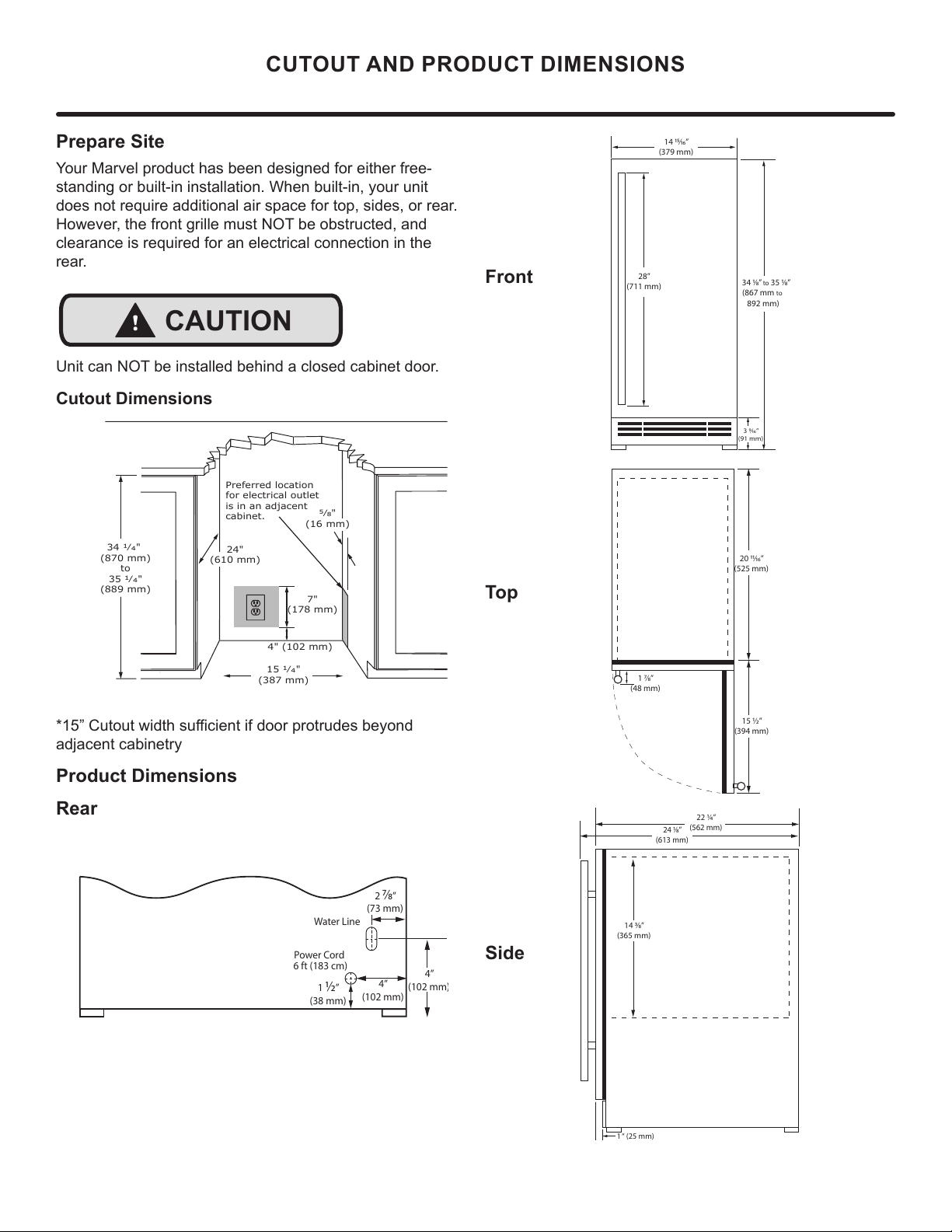
Prepare Site
Your Marvel product has been designed for either free-
standing or built-in installation. When built-in, your unit
does not require additional air space for top, sides, or rear.
However, the front grille must NOT be obstructed, and
clearance is required for an electrical connection in the
rear.
Unit can NOT be installed behind a closed cabinet door.
Cutout Dimensions
´&XWRXWZLGWKVXႈFLHQWLIGRRUSURWUXGHVEH\RQG
adjacent cabinetry
Product Dimensions
Rear
CUTOUT AND PRODUCT DIMENSIONS
!
CAUTION
4" (102 mm)
7"
(178 mm)
15 ȟȯ"
(387 mm)
34 ȟȯ"
(870 mm)
to
35 ȟȯ"
(889 mm)
Preferred location
for electrical outlet
is in an adjacent
cabinet.
24"
(610 mm)
ΑȟΞ"
(16 mm)
4”
(102 mm)
1
½
”
(38 mm)
2
⁄
”
(73 mm)
4”
(102 mm
)
Water Line
Power Cord
6 ft (183 cm)
Front
Top
Side
14 ⁄”
(379 mm)
3 ⁄”
(91 mm)
28”
(711 mm)
34 ⁄”
to 35 ⁄”
(867 mm to
892 mm)
1 ⁄”
(48 mm)
15 ½”
(394 mm)
20 ⁄”
(525 mm)
14 ⁄”
(365 mm)
22 ¼”
(562 mm)
24 ⁄”
(613 mm)
1 “ (25 mm)
7
Side-by-Side Installation
Two units may be installed side-by-side.
Cutout width for a side-by-side installation is the cutout
dimension of a single unit times two.
No trim kit is required. However, 1/4" (6 mm) of space
needs to be maintained between the units to ensure
unobstructed door swing.
Units must operate from separate, properly grounded
electrical receptacles placed according to each unit’s
electrical specifications requirements.
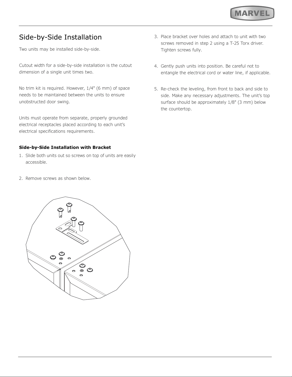
Side-by-Side Installation with Bracket
1. Slide both units out so screws on top of units are easily
accessible.
2. Remove screws as shown below.
3. Place bracket over holes and attach to unit with two
screws removed in step 2 using a T-25 Torx driver.
Tighten screws fully.
4. Gently push units into position. Be careful not to
entangle the electrical cord or water line, if applicable.
5. Re-check the leveling, from front to back and side to
side. Make any necessary adjustments. The unit’s top
surface should be approximately 1/8" (3 mm) below
the countertop.
8
INSTALLING THE ANTI-TIP DEVICE
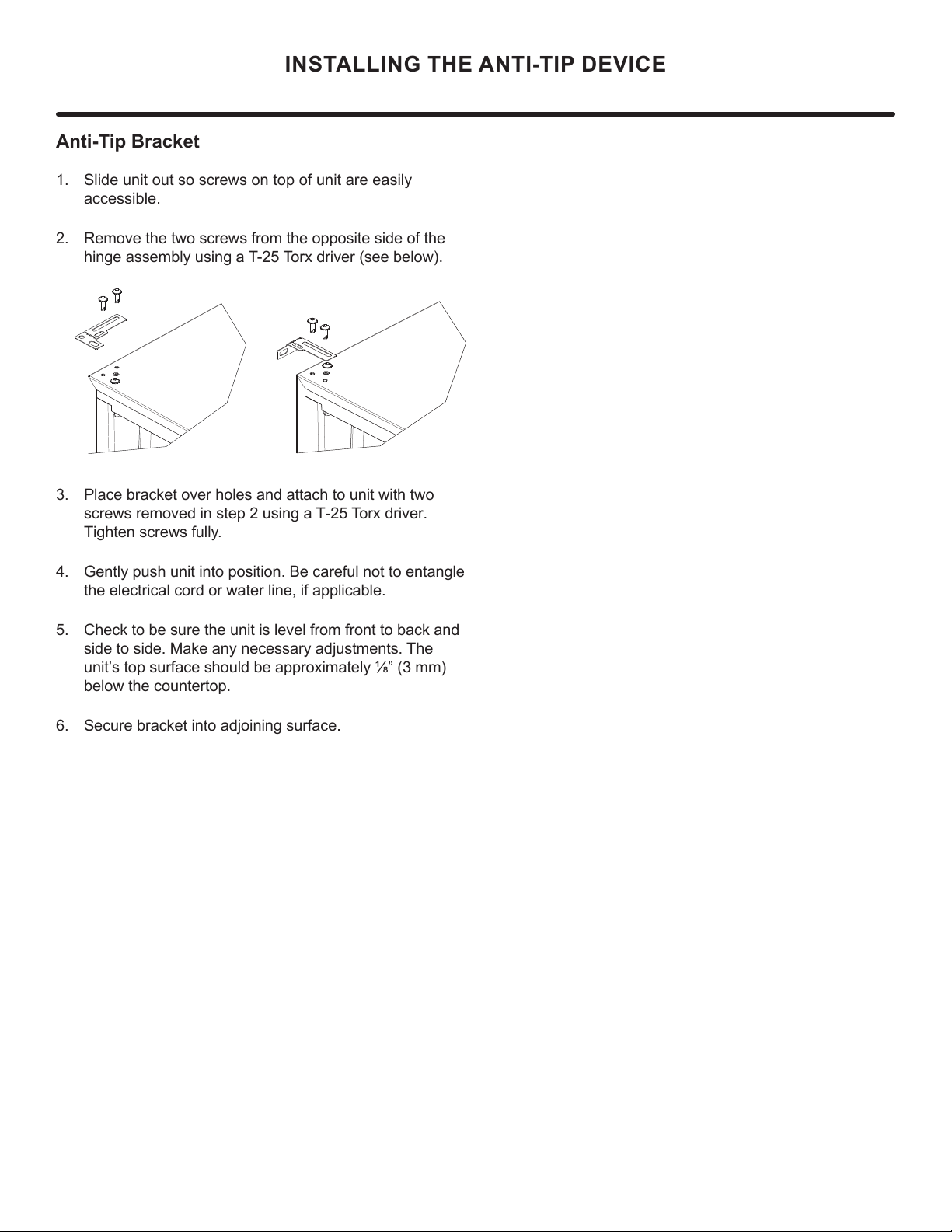
Anti-Tip Bracket
1. Slide unit out so screws on top of unit are easily
accessible.
2. Remove the two screws from the opposite side of the
hinge assembly using a T-25 Torx driver (see below).
Place bracket over holes and attach to unit with two
screws removed in step 2 using a T-25 Torx driver.
Tighten screws fully.
Gently push unit into position. Be careful not to entangle
the electrical cord or water line, if applicable.
Check to be sure the unit is level from front to back and
side to side. Make any necessary adjustments. The
unit’s top surface should be approximately ¹»” (3 mm)
below the countertop.
Secure bracket into adjoining surface.
9
DOOR REVERSAL
Door Adjustments
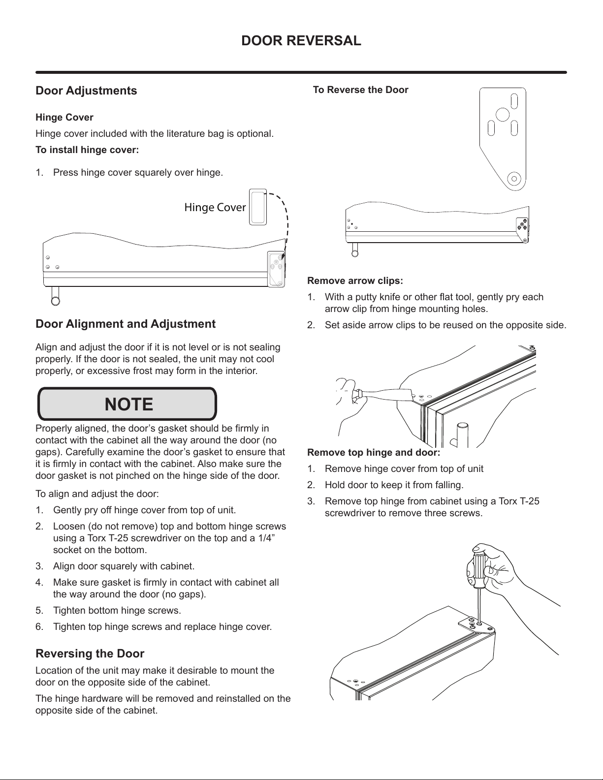
Hinge Cover
Hinge cover included with the literature bag is optional.
To install hinge cover:
1. Press hinge cover squarely over hinge.
Door Alignment and Adjustment
Align and adjust the door if it is not level or is not sealing
properly. If the door is not sealed, the unit may not cool
properly, or excessive frost may form in the interior.
3URSHUO\DOLJQHGWKHGRRU¶VJDVNHWVKRXOGEH¿UPO\LQ
contact with the cabinet all the way around the door (no
gaps). Carefully examine the door’s gasket to ensure that
LWLV¿UPO\LQFRQWDFWZLWKWKHFDELQHW$OVRPDNHVXUHWKH
door gasket is not pinched on the hinge side of the door.
To align and adjust the door:
1. *HQWO\SU\RႇKLQJHFRYHUIURPWRSRIXQLW
2. Loosen (do not remove) top and bottom hinge screws
using a Torx T-25 screwdriver on the top and a 1/4”
socket on the bottom.
3. Align door squarely with cabinet.
4. 0DNHVXUHJDVNHWLV¿UPO\LQFRQWDFWZLWKFDELQHWDOO
the way around the door (no gaps).
5. Tighten bottom hinge screws.
6. Tighten top hinge screws and replace hinge cover.
Reversing the Door
Location of the unit may make it desirable to mount the
door on the opposite side of the cabinet.
The hinge hardware will be removed and reinstalled on the
opposite side of the cabinet.
Hinge Cover
NOTE
To Reverse the Door
Remove arrow clips:
1. :LWKDSXWW\NQLIHRURWKHUÀDWWRROJHQWO\SU\HDFK
arrow clip from hinge mounting holes.
2. Set aside arrow clips to be reused on the opposite side.
Remove top hinge and door:
1. Remove hinge cover from top of unit
2. Hold door to keep it from falling.
3. Remove top hinge from cabinet using a Torx T-25
screwdriver to remove three screws.
10
DOOR REVERSAL
1. 5HPRYHGRRUE\WLOWLQJIRUZDUGDQGOLIWLQJGRRURႇ
bottom hinge. Retain shoulder washers; they will be
reused.
2. Insert arrow clips into holes
Remove bottom hinge:
1. Remove bottom hinge from cabinet using a 1/4” socket.
2. Remove corresponding screws on opposite side of
cabinet. On some models there may be a nut behind
one or both screws on either side.
Install bottom hinge:
Install two or three screws, depending on model. Replace
nuts if used.
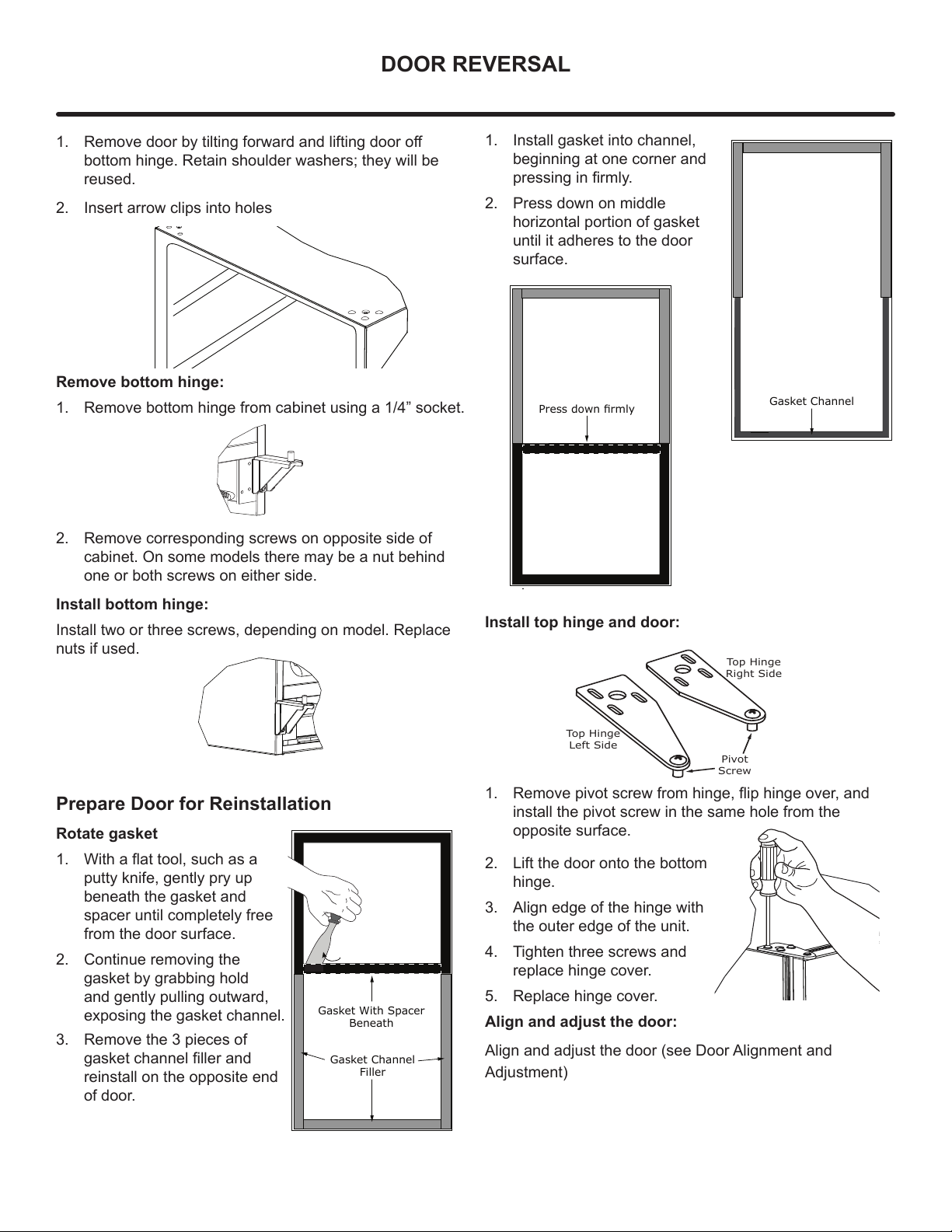
Prepare Door for Reinstallation
Rotate gasket
1. :LWKDÀDWWRROVXFKDVD
putty knife, gently pry up
beneath the gasket and
spacer until completely free
from the door surface.
2. Continue removing the
gasket by grabbing hold
and gently pulling outward,
exposing the gasket channel.
3. Remove the 3 pieces of
gasket channel filler and
reinstall on the opposite end
of door.
Gasket Channel
Filler
Gasket With Spacer
Beneath
1. Install gasket into channel,
beginning at one corner and
pressing in firmly.
2. Press down on middle
horizontal portion of gasket
until it adheres to the door
surface.
Install top hinge and door:
1. 5HPRYHSLYRWVFUHZIURPKLQJHÀLSKLQJHRYHUDQG
install the pivot screw in the same hole from the
opposite surface.
2. Lift the door onto the bottom
hinge.
3. Align edge of the hinge with
the outer edge of the unit.
4. Tighten three screws and
replace hinge cover.
5. Replace hinge cover.
Align and adjust the door:
Align and adjust the door (see Door Alignment and
Adjustment)
Gasket Channel
3UHVVGRZQɟUPO\
Top Hinge
Right Side
Top Hinge
Left Side
Pivot
Screw
11
Integrated Panel Dimensions
'XHWRGLႇHUHQFHVLQVXUURXQGLQJFDELQHWU\WKHSDQHO
PD\QRWSHUIHFWO\DOLJQZLWKGRRU7KHSURFHGXUHEHORZ
LVGHVLJQHGWRSURYLGHD¿QLVKHGLQWHJUDWHGSDQHOWKDW
VHDPOHVVO\LQWHJUDWHVZLWKVXUURXQGLQJFDELQHWU\
7KHGRRUSDQHOPXVWQRWZHLJKPRUHWKDQOEVNJ
,WLVLPSRUWDQWWRHQVXUHWKDWDOOGULOOHGKROHVDUHGULOOHGWR
WKHFRUUHFWGHSWKLQRUGHUWRDYRLGVSOLWVLQWKHZRRGZKHQ
KDUGZDUHLVLQVWDOOHG
:KHQDSSO\LQJDQLQWHJUDWHGSDQHOWRDXQLWHQVXUHWKDW
ERWKVLGHVDUH¿QLVKHGLQRUGHUWRSUHYHQWZDUSLQJ,QVRPH
SDQHOLQVWDOODWLRQVWKHSDQHOPD\EHYLVLEOHWKURXJKWKH
JODVVZKLOHWKHGRRULVRSHQ
$IXOOLQWHJUDWHGGRRUSDQHOFRPSOHWHO\FRYHUVWKHGRRU
IUDPHDQGSURYLGHVDEXLOWLQDSSHDUDQFH
Integrated Panel Preparation
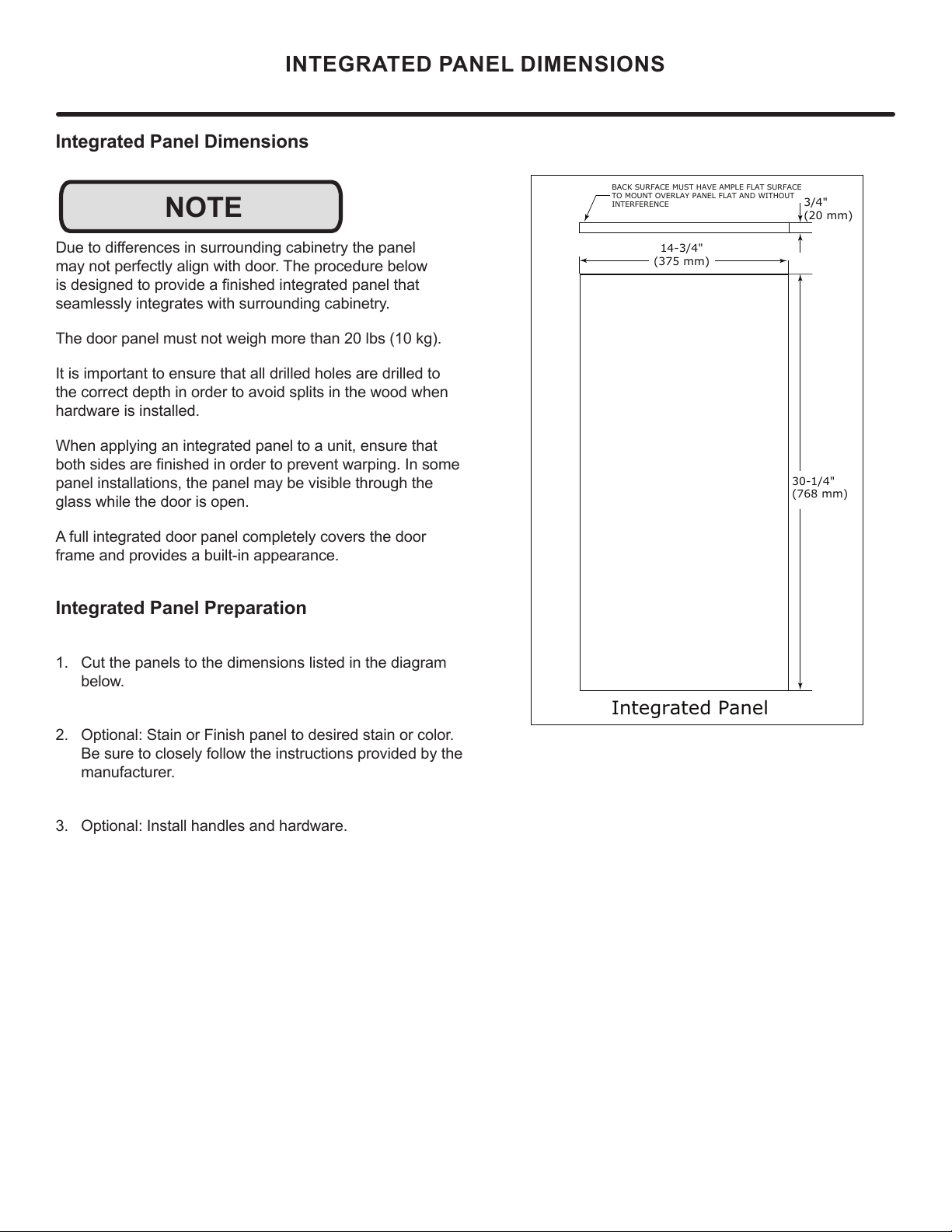
&XWWKHSDQHOVWRWKHGLPHQVLRQVOLVWHGLQWKHGLDJUDP
EHORZ
2SWLRQDO6WDLQRU)LQLVKSDQHOWRGHVLUHGVWDLQRUFRORU
%HVXUHWRFORVHO\IROORZWKHLQVWUXFWLRQVSURYLGHGE\WKH
PDQXIDFWXUHU
2SWLRQDO,QVWDOOKDQGOHVDQGKDUGZDUH
INTEGRATED PANEL DIMENSIONS
NOTE
BACK SURFACE MUST HAVE AMPLE FLAT SURFACE
TO MOUNT OVERLAY PANEL FLAT AND WITHOUT
INTERFERENCE
3/4"
(20 mm)
Integrated Panel
14-3/4"
(375 mm)
30-1/4"
(768 mm)
12
INTEGRATED PANEL INSTALLATION
Integrated Panel Installation
1. Fully open door.
2. Starting at corner, pull gasket away
from door.
3. Continue to pull gasket free from
gasket channel.
4. Upon removal, lay gasket down on a
ÀDWVXUIDFH
5. Partially loosen the 3 screws, securing the top hinge to
the cabinet.
6. Align the panel with the outside edge (opposite the
hinge) and high enough to align with the highest point
in the door.
7. Insert panel underneath top hinge and apply upward
pressure while bringing the lower portion of the
SDQHOÀXVKWRWKHGRRULQVLGHWKHORZHUKLQJH7KH
SDQHOZLOO¿WVQXJJO\
$OLJQGRRUZLWKFDELQHW7LJKWHQWKHWRSVFUHZV
securing the top hinge to the cabinet.
'XHWRGLႇHUHQFHVLQÀRRUFRQVWUXFWLRQRUVXUURXQGLQJ
FDELQHWU\WKHSDQHOPD\QRWVLWÀXVKZLWKWKHWRSRIWKH
door.
Align Panel
Against
Door/Drawe
Edge First
Align Top Of Panel With Highest Point Of Door/Drawe
r
NOTE
Door
Panel
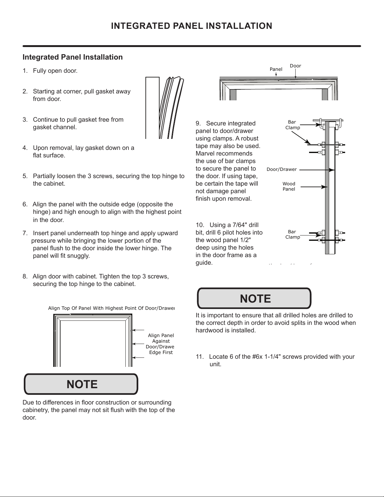
9. Secure integrated
panel to door/drawer
using clamps. A robust
tape may also be used.
Marvel recommends
the use of bar clamps
to secure the panel to
the door. If using tape,
be certain the tape will
not damage panel
¿QLVKXSRQUHPRYDO
10. Using a 7/64" drill
bit, drill 6 pilot holes into
the wood panel 1/2"
deep using the holes
in the door frame as a
guide.
It is important to ensure that all drilled holes are drilled to
the correct depth in order to avoid splits in the wood when
hardwood is installed.
11. Locate 6 of the #6x 1-1/4" screws provided with your
unit.
th d /d f
Wood
Panel
Door/Drawer
Bar
Clamp
Bar
Clamp
NOTE
13
11. Locate 6 of the #6x 1-1/4" screws provided with your
unit.
12. Using a Phillips screwdriver, place one screw
into each of the 6 pilot holes and screw down. Do not
overtighten screws.
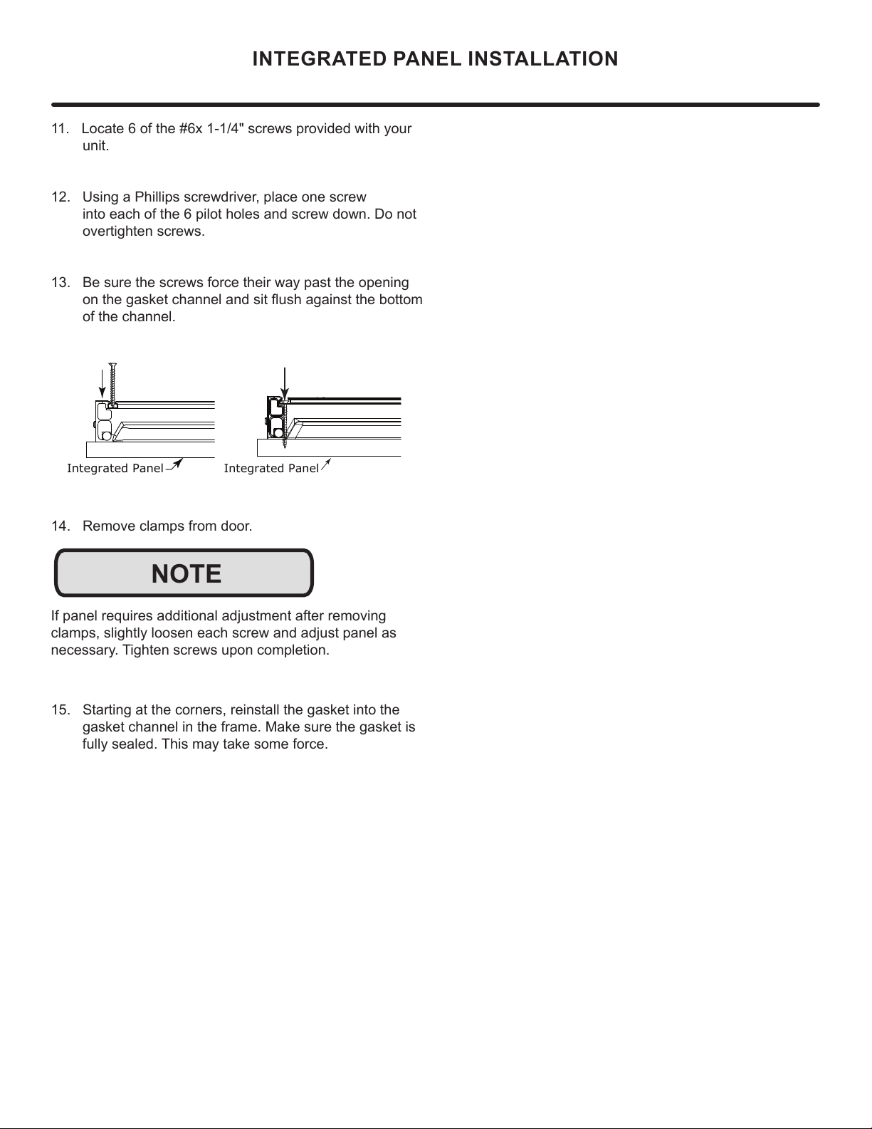
13. Be sure the screws force their way past the opening
RQWKHJDVNHWFKDQQHODQGVLWÀXVKDJDLQVWWKHERWWRP
of the channel.
14. Remove clamps from door.
If panel requires additional adjustment after removing
clamps, slightly loosen each screw and adjust panel as
QHFHVVDU\7LJKWHQVFUHZVXSRQFRPSOHWLRQ
15. Starting at the corners, reinstall the gasket into the
gasket channel in the frame. Make sure the gasket is
IXOO\VHDOHG7KLVPD\WDNHVRPHIRUFH
Integrated Panel
Inte
g
rated Panel
NOTE
INTEGRATED PANEL INSTALLATION
14
INSTALLING THE WATER SUPPLY
Prepare Plumbing
Plumbing installation must observe all state and local
codes. All water and drain connections MUST BE made by
DOLFHQVHGTXDOL¿HGSOXPELQJFRQWUDFWRU)DLOXUHWRIROORZ
recommendations and instructions may result in damage
and/or harm.
Water Supply Connection
:KHQFRQQHFWLQJWKHZDWHUVXSSO\SOHDVHQRWHWKH
IROORZLQJ
• %HIRUHLQVWDOOLQJWKHXQLWDQGFRQQHFWLQJWRWKHFROG
ZDWHUVXSSO\UHYLHZWKHORFDOSOXPELQJFRGHV
• 7KHZDWHUSUHVVXUHVKRXOGEHEHWZHHQDPLQLPXPRI
DQGDPD[LPXPRISVLDQGN3D
• :DWHUKDVOHVVWKDQPJ/SSPWRWDOGLVVROYHG
VROLGVDQGKDUGQHVVOHYHOEHORZPJ/SSP²LH
EHORZJUDLQVSHUJDOORQ&KHFNE\XVLQJ7'6PHWHU
RUFRQVXOWLQJZLWKORFDOZDWHUFRPSDQ\
• 7'6DQGRUZDWHUKDUGQHVVDERYHWKHVHOLPLWVVKRXOG
be treated with a reverse osmosis system or other
¿OWUDWLRQV\VWHP
• 6RIWHQHGZDWHULVQRWUHFRPPHQGHGDVLWPD\UHVXOWLQ
VRIWHULFHWKDQGHVLUHG
• &RQQHFWLRQWRWKHZDWHUPDLQLVPDGHZLWKKRVHVHW
only.
• +RVHVHWPXVWEHQHZQRWUHXVHGDQGLQFRPSOLDQFH
ZLWK,(&
• 7KHZDWHUOLQH0867KDYHDVKXWRႇYDOYHLQWKH
VXSSO\OLQH
• 7KHZDWHUOLQHVKRXOGEHORRSHGLQWRFRLOV7KLVZLOO
DOORZWKHXQLWWREHUHPRYHGIRUFOHDQLQJDQGVHUYLFLQJ
0DNHFHUWDLQWKDWWKHWXELQJLVQRWSLQFKHGRUGDPDJHG
during installation.
!
CAUTION
'RQRWXVHDQ\SODVWLFZDWHUVXSSO\OLQH7KHOLQHLVXQGHU
SUHVVXUHDWDOOWLPHV3ODVWLFPD\FUDFNRUUXSWXUHZLWKDJH
DQGFDXVHGDPDJHWR\RXUKRPH'RQRWXVHWDSHRUMRLQW
FRPSRXQGZKHQDWWDFKLQJDEUDLGHGÀH[LEOHZDWHUVXSSO\
OLQHWKDWLQFOXGHVDUXEEHUJDVNHW7KHJDVNHWSURYLGHV
DQDGHTXDWHVHDO±RWKHUPDWHULDOVFRXOGFDXVHEORFNDJH
RIWKHYDOYH)DLOXUHWRIROORZUHFRPPHQGDWLRQVDQG
LQVWUXFWLRQVPD\UHVXOWLQGDPDJHDQGRUKDUPÀRRGLQJRU
YRLGWKHSURGXFWZDUUDQW\8VHQHZKRVHVHW'RQRWUHXVH
old hose set.
7XUQRႇZDWHUVXSSO\DQGGLVFRQQHFWHOHFWULFDOVXSSO\WR
XQLWSULRUWRLQVWDOODWLRQ8VHFDXWLRQZKHQKDQGOLQJEDFN
SDQHO7KHHGJHVFRXOGEHVKDUS
!
CAUTION
!
CAUTION
15
INSTALLING THE WATER SUPPLY
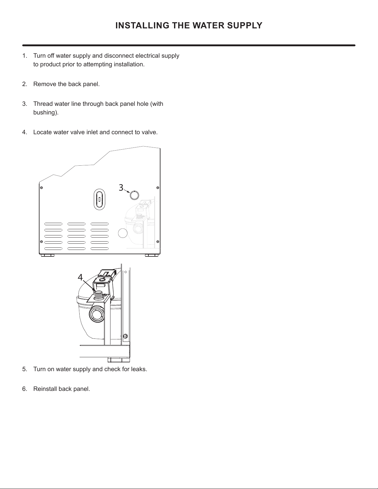
7XUQRႇZDWHUVXSSO\DQGGLVFRQQHFWHOHFWULFDOVXSSO\
WRSURGXFWSULRUWRDWWHPSWLQJLQVWDOODWLRQ
2. 5HPRYHWKHEDFNSDQHO
7KUHDGZDWHUOLQHWKURXJKEDFNSDQHOKROHZLWK
EXVKLQJ
4. Locate water valve inlet and connect to valve.
5. 7XUQRQZDWHUVXSSO\DQGFKHFNIRUOHDNV
5HLQVWDOOEDFNSDQHO
3
4
16
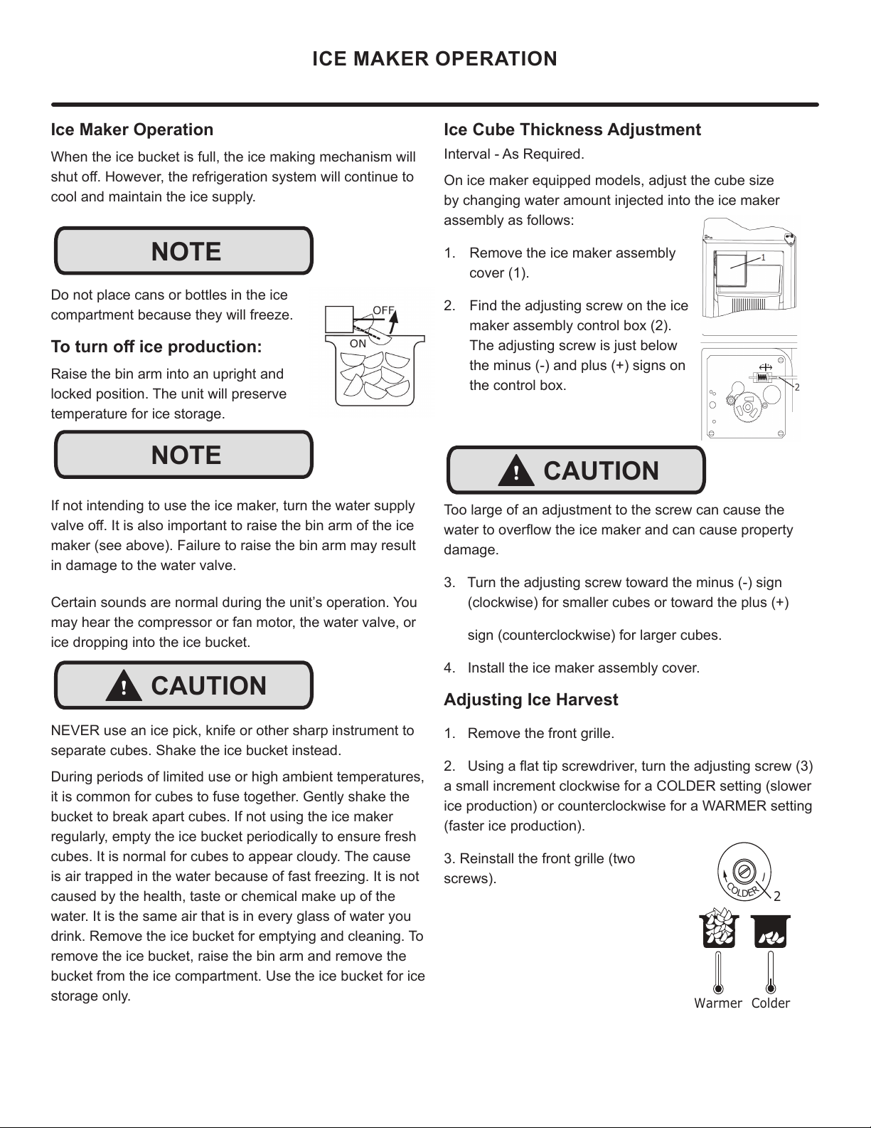
Ice Cube Thickness Adjustment
Interval - As Required.
On ice maker equipped models, adjust the cube size
by changing water amount injected into the ice maker
assembly as follows:
1. Remove the ice maker assembly
cover (1).
2. Find the adjusting screw on the ice
maker assembly control box (2).
The adjusting screw is just below
the minus (-) and plus (+) signs on
the control box.
Too large of an adjustment to the screw can cause the
ZDWHUWRRYHUÀRZWKHLFHPDNHUDQGFDQFDXVHSURSHUW\
damage.
3. Turn the adjusting screw toward the minus (-) sign
(clockwise) for smaller cubes or toward the plus (+)
sign (counterclockwise) for larger cubes.
4. Install the ice maker assembly cover.
Adjusting Ice Harvest
1. Remove the front grille.
8VLQJDÀDWWLSVFUHZGULYHUWXUQWKHDGMXVWLQJVFUHZ
a small increment clockwise for a COLDER setting (slower
ice production) or counterclockwise for a WARMER setting
(faster ice production).
3. Reinstall the front grille (two
screws).
Ice Maker Operation
When the ice bucket is full, the ice making mechanism will
VKXWRႇ+RZHYHUWKHUHIULJHUDWLRQV\VWHPZLOOFRQWLQXHWR
cool and maintain the ice supply.
Do not place cans or bottles in the ice
compartment because they will freeze.
7RWXUQRႇLFHSURGXFWLRQ
Raise the bin arm into an upright and
locked position. The unit will preserve
temperature for ice storage.
If not intending to use the ice maker, turn the water supply
YDOYHRႇ,WLVDOVRLPSRUWDQWWRUDLVHWKHELQDUPRIWKHLFH
maker (see above). Failure to raise the bin arm may result
in damage to the water valve.
Certain sounds are normal during the unit’s operation. You
may hear the compressor or fan motor, the water valve, or
ice dropping into the ice bucket.
NEVER use an ice pick, knife or other sharp instrument to
separate cubes. Shake the ice bucket instead.
During periods of limited use or high ambient temperatures,
it is common for cubes to fuse together. Gently shake the
bucket to break apart cubes. If not using the ice maker
regularly, empty the ice bucket periodically to ensure fresh
cubes. It is normal for cubes to appear cloudy. The cause
is air trapped in the water because of fast freezing. It is not
caused by the health, taste or chemical make up of the
water. It is the same air that is in every glass of water you
drink. Remove the ice bucket for emptying and cleaning. To
remove the ice bucket, raise the bin arm and remove the
bucket from the ice compartment. Use the ice bucket for ice
storage only.
ICE MAKER OPERATION
NOTE
NOTE
!
CAUTION
!
CAUTION
C
O
L
D
E
R
Warmer Colder
17
CARE AND CLEANING
Exterior Cleaning
Stainless door panels, handles and frames can discolor
when exposed to chlorine gas, pool chemicals, saltwater or
cleaners with bleach.
Keep your stainless unit looking new by cleaning with a
good quality all-in-one stainless steel cleaner and polish
monthly. For best results use Claire
®
Stainless Steel
Polish and Cleaner. Comparable products are acceptable.
Frequent cleaning will remove surface contamination that
could lead to rust. Some installations may require cleaning
weekly.
Do not clean with steel wool pads.
Do not use stainless steel cleaners or polishes on any
glass surfaces.
Clean any glass surfaces with a non-chlorine glass cleaner.
'RQRWXVHFOHDQHUVQRWVSHFL¿FDOO\LQWHQGHGIRUVWDLQOHVV
steel on stainless steel surfaces (this includes glass, tile,
and counter cleaners).
If any surface discoloring or rusting appears, clean it
quickly with Bon-Ami
®
or Barkeepers Friend Cleanser
®
and
a nonabrasive cloth. Always clean with the grain. Always
¿QLVKZLWK&ODLUH
®
Stainless Steel Polish and Cleaner or
comparable product to prevent further problems.
Using abrasive pads such as ScotchBrite™ will
cause the graining in the stainless steel to
become blurred.
Rust not cleaned up promptly can penetrate the
surface of the stainless steel and complete
removal of the rust may not be possible.
Integrated Models
To clean integrated panels, use household cleaner per the
cabinet manufacturer’s recommendations.
Interior Cleaning
Disconnect power to the unit.
Clean the interior and all removed components using a mild
nonabrasive detergent and warm solution applied with a soft
sponge or non-abrasive cloth.
Rinse the interior using a soft sponge and clean water.
Do not use any solvent-based or abrasive cleaners. These
types of cleaners may transfer taste and/or odor to the
interior products and damage or discolor the interior.
Defrosting
This unit is a manual defrost model and will require
occasional defrosting. When there is build-up of 1/4”
(6 mm) or more of frost, manually defrost the unit.
DO NOT use an ice pick or other sharp instrument to help speed
up defrosting. These instruments can puncture the inner lining
or damage the cooling unit. DO NOT use any type of heater to
defrost. Using a heater to speed up defrosting can cause personal
injury and damage to the inner lining.
!
CAUTION
18
CARE AND CLEANING
To Defrost:
1. Disconnect power to the unit.
2. Remove ice bucket and discard ice.
3. Place towel or other absorbent material on bottom of
ice bin.
4. Fill the ice bucket half full with warm, not hot water.
This will help the unit defrost faster.
5. Place the ice bucket back into the unit on top of the
towel or other absorbent material.
6. Prop the door in an open position (2 in. [50 mm]
minimum).
7. After about 1 hour remove the ice bin and discard
water.
8. Allow the frost to melt naturally.
9. After the frost melts completely clean the interior and
all removed components. (See Interior Cleaning).
DO NOT clean ice bucket using a dishwasher. The bucket
is not dishwasher safe and will be damaged.
10. When the interior is dry, reconnect power and turn unit
on.
To safeguard against contaminates in ice, discard
¿UVWWKUHHEDWFKHVRILFHDIWHUGHIURVWLQJ
NOTE
NOTE
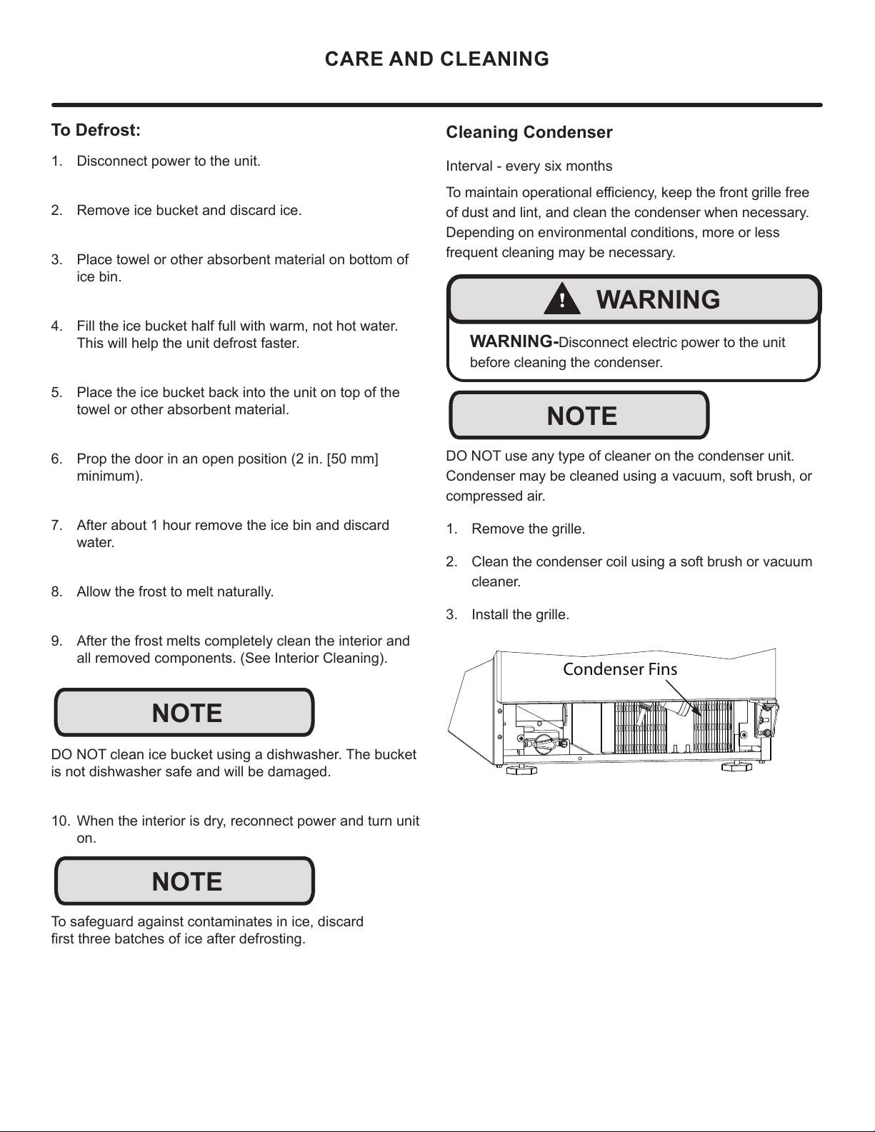
Cleaning Condenser
Interval - every six months
7RPDLQWDLQRSHUDWLRQDOHႈFLHQF\NHHSWKHIURQWJULOOHIUHH
of dust and lint, and clean the condenser when necessary.
Depending on environmental conditions, more or less
frequent cleaning may be necessary.
DO NOT use any type of cleaner on the condenser unit.
Condenser may be cleaned using a vacuum, soft brush, or
compressed air.
1. Remove the grille.
2. Clean the condenser coil using a soft brush or vacuum
cleaner.
3. Install the grille.
Condenser Fins
!
WARNING
WARNING-Disconnect electric power to the unit
before cleaning the condenser.
NOTE
19
EXTENDED NON-USE
Extended Non-Use
Vacation/Holiday - Prolonged Shutdown
The following steps are recommended for periods of
extended non-use:
1. Remove all consumable content from the unit.
2. Disconnect the power cord from its outlet/socket and
leave it disconnected until the unit is returned to service.
3. 7XUQRႇWKHZDWHUVXSSO\
4. If ice is on the evaporator, allow ice to thaw naturally.
5. Clean and dry the interior of the cabinet. Ensure all
water has been removed from the unit.
6. Disconnect the water and drain line (if applicable)
making sure all water is removed from the lines.
7. The door must remain open to prevent formation of
mold and mildew. Open door a minimum of 2” (50 mm)
to provide the necessary ventilation.
Winterization
If the unit will be exposed to temperatures of 40°F (5°C)
or less, the steps above must be followed. In addition,
P60 drain pumps in clear ice machines must be drained
according to the following procedure:
1. Remove the drain pump from the ice machine.
2. Drain the water in the pump’s reservoir by turning the
pump upside down and allowing the water to drain
WKURXJKWKHSXPS¶VLQOHWDQGYHQWWXEH¿WWLQJV
3. After water is drained, reinstall the drain pump and
reattach all connections.
For questions regarding winterization, please call Marvel at
616.754.5601.
Damage caused by freezing temperatures is not covered by
the warranty. Do not put anti-freeze in your unit.
!
CAUTION
20
If Service is Required:
• If the product is within the rst year warranty period
please contact your dealer or call Marvel Customer
Service at 616.754.5601 for directions on how to obtain
warranty coverage in your area.
• If the product is outside the rst year warranty period,
Marvel Customer Service can provide recommenda-
tions of service centers in your area. A listing of autho-
rized service centers is also available at www.marvelre-
frigeration.com under the service and support section.
• In all correspondence regarding service, be sure to
give the service number, serial number, and proof of
purchase.
• Try to have information or description of nature of the
problem, how long the appliance has been running, the
room temperature, and any additional information that
may be helpful in quickly solving the problem.
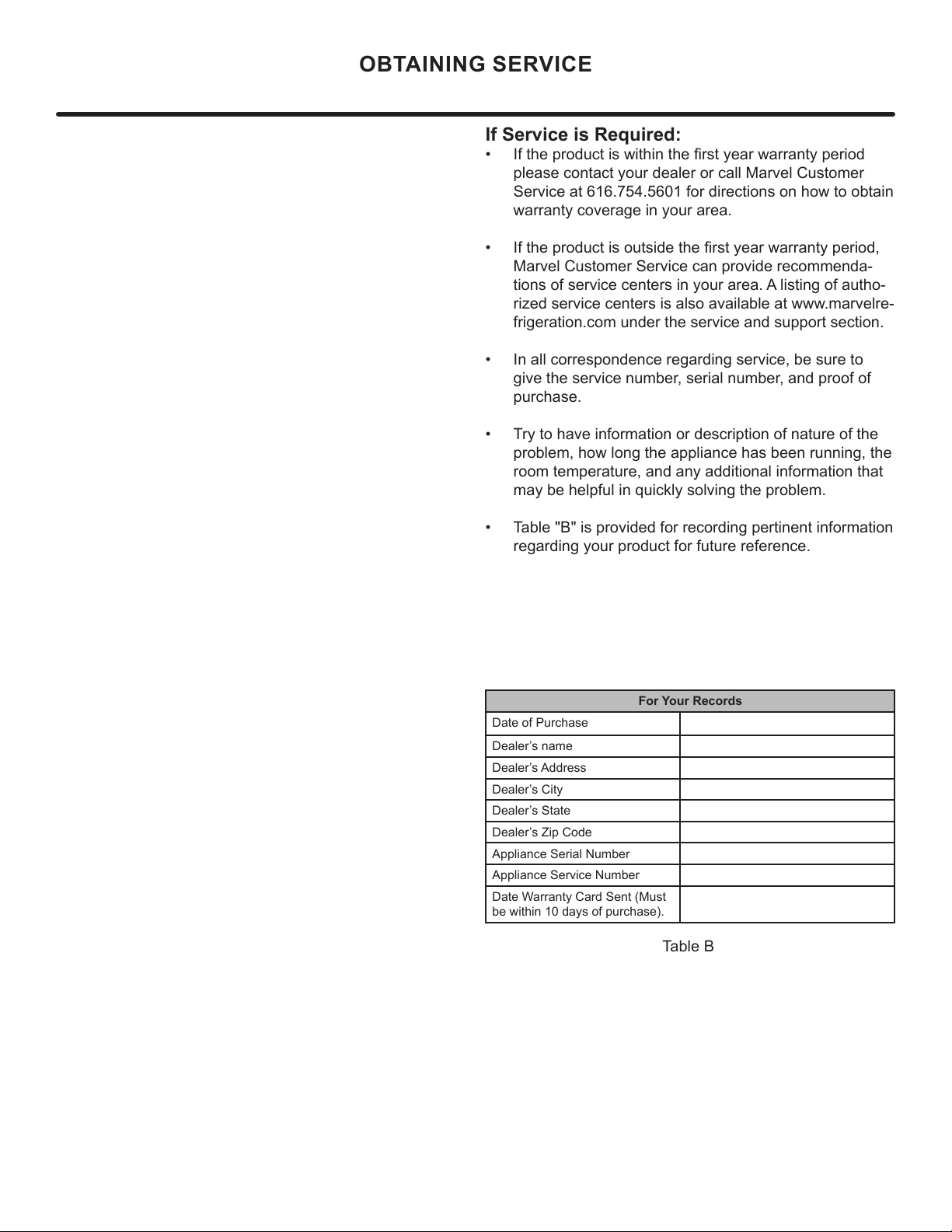
• Table "B" is provided for recording pertinent information
regarding your product for future reference.
For Your Records
Date of Purchase
Dealer’s name
Dealer’s Address
Dealer’s City
Dealer’s State
Dealer’s Zip Code
Appliance Serial Number
Appliance Service Number
Date Warranty Card Sent (Must
be within 10 days of purchase).
Table B
OBTAINING SERVICE
21
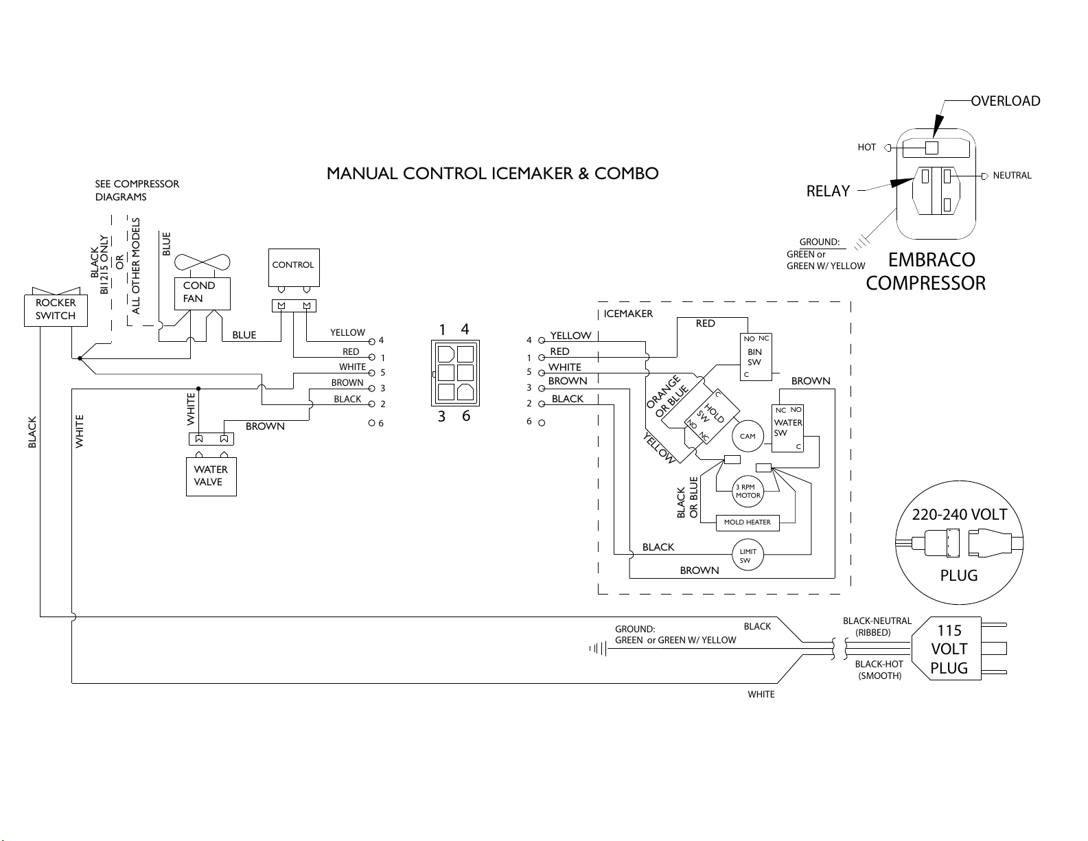
MANUAL CONTROL ICEMAKER & COMBO
ROCKER
SWITCH
COND
FAN
WATER
VALVE
SEE COMPRESSOR
DIAGRAMS
BROWN
BLUE
BLUE
WHITE
BLACK
BLACK
WHITE
BIN
SW
NO
NC
C
WATER
SW
NC
NO
C
HOLD
SW
NO
NC
C
CAM
3 RPM
MOTOR
LIMIT
SW
MOLD HEATER
YELLOW
RED
WHITE
BROWN
BLACK
RED
YELLOW
BROWN
BLACK
BROWN
ORANGE
OR BLUE
BLACK
OR BLUE
OR
ALL OTHER MODELS
ICEMAKER
BI1215 ONLY
CONTROL
GROUND:
GREEN or GREEN W/ YELLOW
115
VOLT
PLUG
220-240 VOLT
PLUG
BLACK-HOT
(SMOOTH)
BLACK-NEUTRAL
(RIBBED)
BLACK
WHITE
RED
YELLOW
BROWN
WHITE
BLACK
1
3
6
4
4
1
5
3
2
6
4
1
5
3
2
6
NEUTRAL
H
OT
RELAY
EMBRACO
COMPRESSOR
GREEN or
GREEN W/ YELLOW
GROUND:
OVERLOAD
22
Product Liability
E
V
G
The original refrigeration experts since 1892.
23
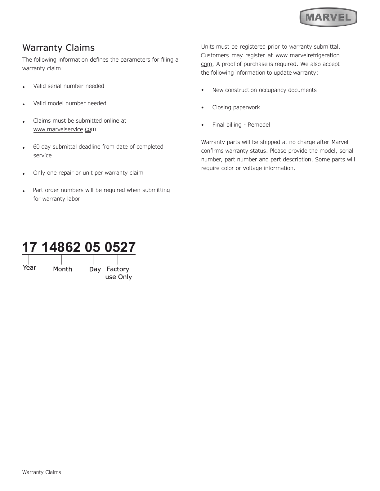
Warranty Claims
17 14862 05 0527
1
I I I
Year
Warranty Claims
D
ay
Factory
use Only
M
Month
24
Ordering Replacement Parts
O
"
"
6
6
6
M
M
M
M
m.
Ordering Replacement Parts
25
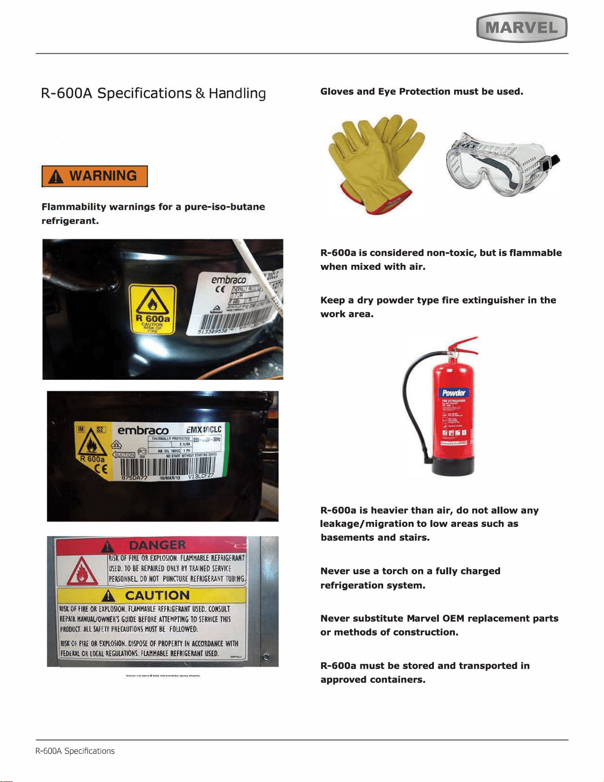
R-600A Specifications
&
H
an
dl
in
g
R-600A Specications
,
.
'
26
IA WARNING I
27
SYSTEM REPAIR
R-600A Specications
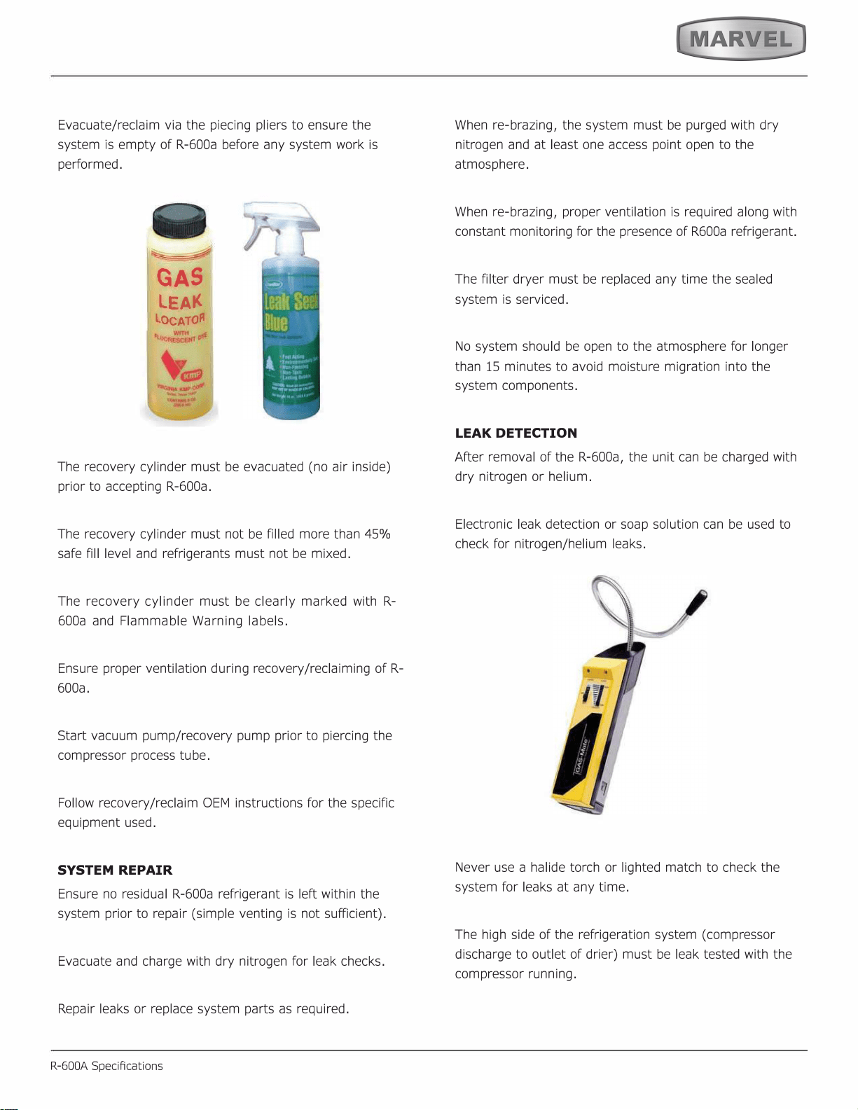
LEAK DETECTION
28
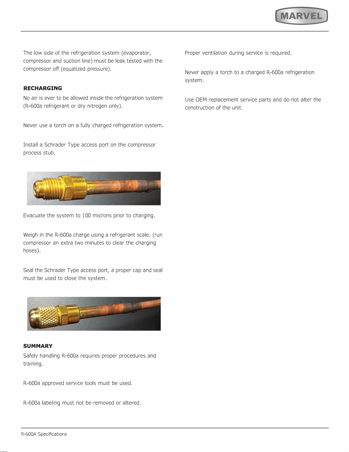
RECHARGING
SUMMARY
29
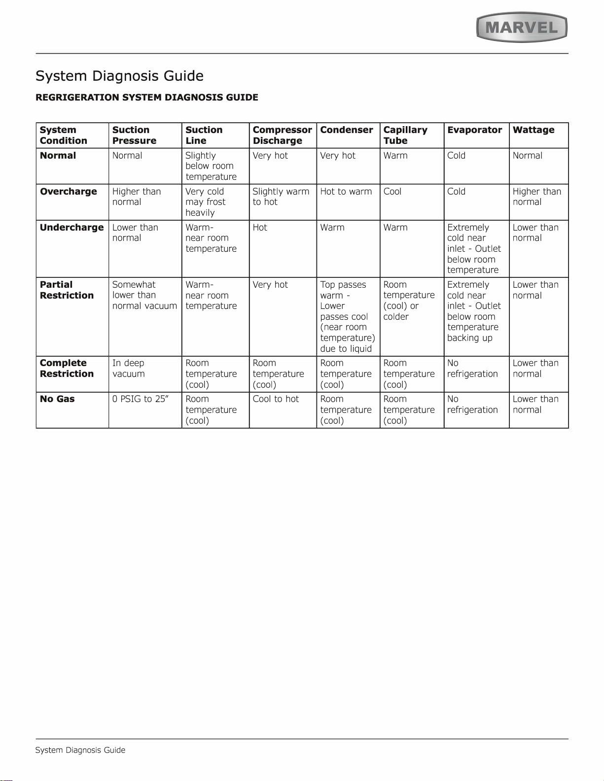
System Diagnosis Guide
System Diagnosis Guide
30
Defrost
Defrost
This unit defrosts every 4 hours of compressor runtime for 45 minutes. If you have verified that the unit does
not have an ambient air leak, utilize the Control Operation - Service section and adjust unit to defrost every
3 hours for 60 minutes. Also, adjust the #2 thermistor to -4 instead of 0.
31
REPLACE ICE MAKER
The new ice maker assembly you have recieved will have a
plug-in connection. In some instances, you may need to cut
plug from cable and hard-wire the connections.
Remove Ice Maker
1. Unplug the unit.
2. Disconnect ice maker wire harness at plug
3. Disconnect thermistor plug.
4. Remove water inlet tube.
5. Remove front cover.
6. Advance ejector blade to the 3 o'clock position by
turning 5/16" hex head on the small brass gear
counterclockwise.
7. Remove three screws from the wall freezer housing.
8. Remove ice maker assembly.
Install Ice Maker
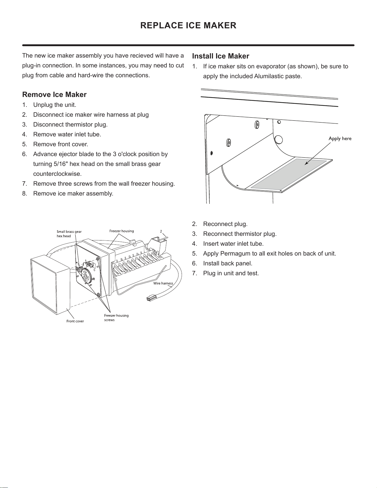
1. If ice maker sits on evaporator (as shown), be sure to
apply the included Alumilastic paste.
2. Reconnect plug.
3. Reconnect thermistor plug.
4. Insert water inlet tube.
5. Apply Permagum to all exit holes on back of unit.
6. Install back panel.
7. Plug in unit and test.
Apply here
32
HOUSEHOLD PRODUCT WARRANTY
Marvel Refrigeration (Marvel) Limited Warranty
ONE YEAR LIMITED PARTS & LABOR WARRANTY
For one year from the date of original purchase, this warranty covers all parts and labor to repair or replace any part of the product that proves to
be defecve in materials or workmanship. For products installed and used for normal residenal use, material cosmec defects are included in this
warranty, with coverage limited to 60 days from the date of original purchase. All service provided by Marvel under the above warranty must be
performed by a Marvel factory authorized servicer, unless otherwise specied by Marvel. Service provided during normal business hours.
TWO YEAR LIMITED PARTS & LABOR WARRANTY (MARVEL PROFESSIONAL PRODUCTS)
For two years from the date of original purchase, this warranty covers all parts and labor to repair or replace any part of the product that proves to
be defecve in materials or workmanship. For products installed and used for normal residenal use, material cosmec defects are included in this
warranty, with coverage limited to 60 days from the date of original purchase. All service provided by Marvel under the above warranty must be
performed by a Marvel factory authorized servicer, unless otherwise specied by Marvel. Service provided during normal business hours.
AVAILABLE THIRD YEAR LIMITED WARRANTY (MARVEL PROFESSIONAL PRODUCTS)
For designated Marvel Professional product, Marvel oers a one year extension of the two year warranty coverage from the date of purchase, free
of charge. To take advantage of this third year warranty, you must register your product with Marvel within 60 days from the date of purchase at
marvelrefrigeration.com and provide proof of purchase. Nugget Ice Machine proof of purchase must include the purchase of an in-line water filter
and filter head to qualify for this additional limited warranty.
LIMITED FIVE YEAR SEALED SYSTEM WARRANTY
For five years from the date of original purchase, Marvel will repair or replace the following parts, labor not included, that prove to be defective in
materials or workmanship: compressor, condenser, evaporator, drier, and all connecting tubing. All service provided by Marvel under the above
warranty must be performed by a Marvel factory authorized servicer, unless otherwise specified by Marvel. Service provided during normal
business hours.
WARRANTY TERMS
These warranties apply only to products installed in any one of the fifty states of the United States, the District of Columbia, or the ten provinces of
Canada. The warranties do not cover any parts or labor to correct any defect caused by negligence, accident or improper use, maintenance, instal-
lation, service, repair, acts of God, fire, flood or other natural disasters. The product must be installed, operated, and maintained in accordance
with the Marvel User Guide.
The remedies described above for each warranty are the only ones that Marvel will provide, either under these warranties or under any warranty
arising by operation of law. Marvel will not be responsible for any consequential or incidental damages arising from the breach of these warranties
or any other warranty, whether express, implied, or statutory. Some states do not allow the exclusion or limitation of incidental or consequential
damages, so the above limitation or exclusion may not apply to you. These warranties give you specific legal rights, and you may also have other
rights which vary from state to state.
Any warranty that may be implied in connection with your purchase or use of the product, including any warranty of merchantability or any war-
ranty fit for a particular purpose is limited to the duration of these warranties, and only extends to five years in duration for the parts described
in the section related to the five year limited warranty above. Some states do not allow limitations on how long an implied warranty lasts, so the
above limitations may not apply to you.
• The warranes only apply to the original purchaser and are non-transferable.
• These warranes cover products installed and used for normal residenal use only.
• The warranes apply to units operated outside only if designed for outdoor use by model and serial number.
• Replacement water lters, light bulbs, and other consumable parts are not covered by these warranes.
• The start of Marvel’s obligaon is limited to four years aer the shipment date from Marvel.
• In-home instrucon on how to use your product is not covered by these warranes.
• Food, beverage, and medicine loss are not covered by these warranes.
• If the product is located in an area where Marvel factory authorized service is not available, you may be responsible for a trip charge or
you may be required to bring the product to a Marvel factory authorized service locaon at your own cost and expense.
• Units purchased aer use as oor displays, and/or cered recondioned units, are covered by the limited one year warranty only and no
coverage is provided for cosmec defects.
• Signal issues related to Wi-Fi connecvity are not covered by these warranes.
For parts and service assistance, or to nd Marvel factory authorized service near you, contact Marvel Refrigeraon:
MarvelRefrigeraon.com • techsupport@MarvelRefrigeraon.com • +616.754.5601
1260 E. Van Deinse St., Greenville, MI 48838
33
All specications and product designs subject to change without notice. Such revisions do not entitle
the buyer to corresponding changes, improvements, additions, replacements or compensation for
previously purchased products.
www.marvelrefrigeration.com
Marvel Refrigeration
1260 E. Van Deinse St.
Greenville MI 48838
616.754.5601
34