Loading ...
Loading ...
3
FIG. 2
FIG. 3
BLACK
NEGRO
BLACK
NEGRO
BLACK
NEGRO
THERMAL
OVERLOAD
SOBRECARGA
TERMICA
THERMOSTAT
TERMOSTATO
BLACK
NEGRO
BLACK
NEGRO
WHITE
BLANCO
WHITE
BLANCO
WHITE
BLANCO
M
FIG. 6
THERMOSTAT
TERMOSTATO
M
WHITE
BLANCO
WHITE
BLANCO
WHITE
BLANCO
WHITE
BLANCO
BLACK
NEGRO
BLACK
NEGRO
BLACK
NEGRO
BLACK
NEGRO
TABS
OREJETAS
FASTEN TO
HOUSING WITH
RETAINING
SCREW HERE
FIJE LA CAJA
CON EL
TORNILLO DE
RETENCION -
AQUI
DISCONNECT FOR
HALF-WATTAGE
DESCONECTE PARA MEDIO
VATIAJE
HEATING
ELEMENT
ELEMENTO
DE CALOR
FACTORY-WIRED
HEATER
(FULL WATTAGE)
CALENTADOR CABLEADO
EN FABRICA
(VATIAJE COMPLETO)
LINE IN LINEA DE ENTRADA
HEATING
ELEMENT
ELEMENTO
DE CALOR
THERMAL
OVERLOAD
SOBRECARGA
TERMICA
CONVERTED 240
VAC HEATER
CALENTADOR 240 VCA
CONVERTIDO
240 VAC LINE IN LINEA DE ENTRADA 240 VCA
INSTALLATION
WARNING: To reduce the risk of fire, do not store or
use gasoline or other flammable vapors and liquids
in the vicinity of the heater.
CAUTION: High temperature, risk of fire, keep
electrical cords, drapery, furnishings, and other
combustibles at least 3 feet (0.9 m) from the front of
the heater and away from the side and rear.
1. Remove housing mask.
Make sure wall has been finished (including paint or
wall paper, etc.). Take out and discard the cardboard
mask from inside of housing.
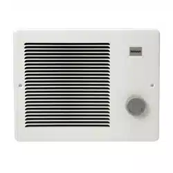
2. Install heater assembly into housing.
Place element end of heater assembly behind the
tabs on the left side of housing. Pivot the assembly
in an fasten with retaining screw from parts bag.
(FIG. 2)
Plug wiring harness into receptacle.
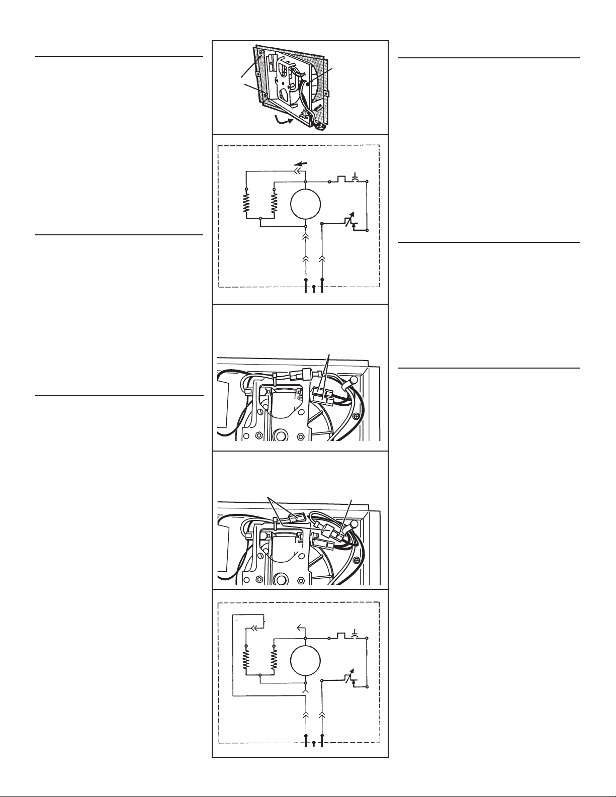
WIRING DIAGRAM
Installation work and electrical wiring must be
done by a qualified person(s) in accordance with
all applicable codes and standards, including fire-
rated construction codes and standards.
Please refer to Figure 3 for the explanation of how this
unit is wired.
INSTALACION
ADVERTENCIA: Para reducir el riesgo de incendio, no
almacene ni use gasolina u otros vapores y líquidos
flamables en las cercanías del calentador.
PRECAUCIÓN: Temperatura alta, el riesgo de incendio,
mantenga los cables eléctricos, cortinas, muebles y
otros materiales combustibles por lo menos 3 pies
(0,9 m) del frente del calentador y lejos de la cara y la
parte trasera.
1. Quite la cubierta de la caja.
Compruebe que la pared se haya terminado (incluyendo
la pared o el empapelamiento, etc.). Saque la cubierta
de cartón de la parte de adentro de la caja y tírela.
2. Instale el conjunto de calentador dentro de la caja.
Coloque el extremo del elemento del conjunto
calentador detrás de las orejetas en el lado izquierdo
de la caja. Meta el conjunto girándolo y fije con tornillo
de retención de la bolsa de las piezas. (FIG. 2)
Enchufe el cable preconfigurado.
DIAGRAMA DE CABLEADO
El trabajo de instalación y el cableado eléctrico deben
estar a cargo de personal capacitado, de acuerdo
con todos los códigos y normas correspondientes,
incluidos los códigos y normas de construcción
específicos sobre protección contra incendios.
Por favor refierase a Figura 3 para la explicación de cómo
cablear esta unidad.
CONVERSIONES DE
CABLEADO OPCIONAL
1. Conversión a mitad de vatiaje. (FIG 4)
El calentador producirá menos calor y usará menos
electricidad si se le convierte a mitad de vatiaje.
Desconecte UNO de los dos (2) alambres negros (con
los terminales aisladas) del motor.
2. Conversión de 120 VCA a 240 VCA. (FIGS. 5 & 6)
(SOLAMENTE Modelos 170 & 174 de 120 VCA
cableados en fábrica).
Estos calentadores se pueden convertir de modo que
puedan funcionar con 240 VCA.
1) Desconecte UNO de los dos (2) alambres negros
(con los terminales aisladas) del motor.
2) Desconecte los dos (2) alambres blancos (con
terminales aisladas). No quite el alambre blanco
de abajo del enlace del cable plástico.
3) Conecte el alambre negro al alambre blanco.
NOTA: Cuando el calentador se convierte de 120 VAC a
240 VAC, no es posible la conversión a mitad de vatiaje.
FIG. 4 - HALF-WATTAGE CONVERSION
CONVERSIÓN DE MEDIO VATIAJE
(2) BLACK WIRES (connected to motor)
(2) CABLES NEGROS (conectados al motor)
FIG. 5 - 120VAC TO 240VAC CONVERSION
CONVERSIÓN DE 120VCA A 240VCA
BLACK WIRE (from motor)
CABLE NEGRO (del motor)
WHITE WIRES
CABLES BLANCOS
MOTOR
MOTOR
OPTIONAL WIRING
CONVERSIONS
1. Conversion to half-wattage. (FIG. 4)
The heater will produce less heat and use less
electricity if converted to half-wattage.
Disconnect ONE of the two (2) black wires (with
insulated terminals) from the motor.
2. 120 VAC to 240 VAC Conversion (FIGS. 5 & 6)
(Factory-wired 120 VAC Models 170 and 174 ONLY)
These heaters can be converted to operate on
240 VAC.
1) Disconnect ONE of the two (2) black wires (with
insulated terminals) from the motor.
2) Disconnect the two (2) white wires (with insu-
lated terminals) from each other. Do not remove
the white wire from beneath plastic wire tie.
3) Connect the black wire to the white wire.
NOTE: When heater is converted from 120 VAC to
240 VAC, half-wattage conversion is not possible.
WHITE
BLANCO
BLACK
NEGRO
BLACK
NEGRO
Loading ...
Loading ...
Loading ...