
Wireless Dual-Tech Detector
User’s Manual
ZHEJIANG DAHUA VISION TECHNOLOGY CO., LTD. V1.0.1
User’s Manual
I
Foreword
General
This manual introduces the installation, functions and operations of the Wireless Dual-Tech Detector
(hereinafter referred to as the "dual-tech detector"). Read carefully before using the device, and keep
the manual safe for future reference.
Safety Instructions
The following signal words might appear in the manual.
Signal Words Meaning
Indicates a high potential hazard which, if not avoided, will result in
death or serious injury.
Indicates a medium or low potential hazard which, if not avoided,
could result in slight or moderate injury.
Indicates a potential risk which, if not avoided, could result in
property damage, data loss, lower performance, or unpredictable
result.
Provides methods to help you solve a problem or save you time.
Provides additional information as the emphasis and supplement to
the text.
Revision History
Version Revision Content Release Time
V1.0.1 Updated technical specifications. March 2023
V1.0.0 First release. November 2022
Privacy Protection Notice
As the device user or data controller, you might collect the personal data of others such as their face,
fingerprints, and license plate number. You need to be in compliance with your local privacy
protection laws and regulations to protect the legitimate rights and interests of other people by
implementing measures which include but are not limited: Providing clear and visible identification
to inform people of the existence of the surveillance area and provide required contact information.
About the Manual
●
The manual is for reference only. Slight differences might be found between the manual and the
product.
●
We are not liable for losses incurred due to operating the product in ways that are not in
compliance with the manual.
●
The manual will be updated according to the latest laws and regulations of related jurisdictions.
For detailed information, see the paper user’s manual, use our CD-ROM, scan the QR code or visit
our official website. The manual is for reference only. Slight differences might be found between
the electronic version and the paper version.

User’s Manual
II
●
All designs and software are subject to change without prior written notice. Product updates
might result in some differences appearing between the actual product and the manual. Please
contact customer service for the latest program and supplementary documentation.
●
There might be errors in the print or deviations in the description of the functions, operations
and technical data. If there is any doubt or dispute, we reserve the right of final explanation.
●
Upgrade the reader software or try other mainstream reader software if the manual (in PDF
format) cannot be opened.
●
All trademarks, registered trademarks and company names in the manual are properties of their
respective owners.
●
Please visit our website, contact the supplier or customer service if any problems occur while
using the device.
●
If there is any uncertainty or controversy, we reserve the right of final explanation.

User’s Manual
III
Important Safeguards and Warnings
This section introduces content covering the proper handling of the dual-tech detector, hazard
protection, and protection of property damage. Read carefully before using the dual-tech detector,
and comply with the guidelines when using it.
Operation Requirements
●
Make sure that the power supply of the dual-tech detector works properly before use.
●
Do not pull out the power cable of the dual-tech detector while it is powered on.
●
Only use the dual-tech detector within the rated power range.
●
Transport, use and store the device under allowed humidity and temperature conditions.
●
Prevent liquids from splashing or dripping on the device. Make sure that there are no objects
filled with liquid on top of the dual-tech detector to avoid liquids flowing into it.
●
Do not disassemble the dual-tech detector.
Installation Requirements
●
Connect the dual-tech detector to the adapter before power on.
●
Strictly abide by local electrical safety standards, and make sure that the voltage in the area is
steady and conforms to the power requirements of the dual-tech detector.
●
Do not connect the dual-tech detector to more than one power supply. Otherwise, the might
become damaged.
●
Observe all safety procedures and wear required protective equipment provided for your use
while working at heights.
●
Do not expose the dual-tech detector to direct sunlight or heat sources.
●
Do not install the dual-tech detector in humid, dusty or smoky places.
●
Install the dual-tech detector in a well-ventilated place, and do not block the ventilator of the
device.
●
Use the power adapter or case power supply provided by the device manufacturer.
●
The power supply must conform to the requirements of ES1 in IEC 62368-1 standard and be no
higher than PS2. Note that the power supply requirements are subject to the device label.
●
Connect class I electrical appliances to a power socket with protective earthing.

User’s Manual
IV
Table of Contents
Foreword
........................................................................................................................................................................................................I
Important Safeguards and Warnings
............................................................................................................................................ III
1 Introduction
............................................................................................................................................................................................ 1
1.1 Overview
........................................................................................................................................................................................ 1
1.2 Technical Specifications
......................................................................................................................................................... 1
2 Checklist
.................................................................................................................................................................................................... 4
3 Design
......................................................................................................................................................................................................... 5
3.1 Appearance
................................................................................................................................................................................... 5
3.2 Dimensions
................................................................................................................................................................................... 6
4 Power On
................................................................................................................................................................................................... 7
5 Adding the Wireless Dual-Tech Detector to the Hub
.......................................................................................................... 8
6 Installation
............................................................................................................................................................................................... 9
6.1 Field of View
................................................................................................................................................................................. 9
6.2 Wall Mount
.................................................................................................................................................................................. 10
6.3 Corner Mount
............................................................................................................................................................................. 10
7 Replacing the Battery
....................................................................................................................................................................... 12
8 Configuration
....................................................................................................................................................................................... 13
8.1 Viewing Status
.......................................................................................................................................................................... 13
8.2 Configuring the Dual-tech Detector
.............................................................................................................................. 14
Appendix 1 Cybersecurity Recommendations
........................................................................................................................ 17

User’s Manual
1
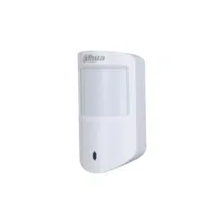
1 Introduction
1.1 Overview
Wireless Dual-tech Detector is a wireless motion detector designed for indoor use. It can detect a
human moving within 12 m of the detector.
1.2 Technical Specifications
This section contains technical specifications of the dual-tech detector. Please refer to the ones that
correspond with your model.
Table 1-1 Technical specification
Type Parameter Description
Port
Indicator
Light
1 × green alarm indicator
Button 1 × power switch
Function
Tamper
Alarm
Yes
Remote
Update
Cloud update
Signal
Strength
Detects signal strength.
Low Battery
Alarm
Yes
Wireless
Carrier
Frequency
DHI-ARD2231-W2(868):
868.0 MHz–868.6 MHz
DHI-ARD2231-W2:
433.1 MHz–434.6 MHz
Communicati
on Distance
DHI-ARD2231-W2(868):
Up to 1,600 m (5249.34 ft)
in an open space.
DHI-ARD2231-W2:
Up to 1200 m (3937.01 ft) in an
open space
Transmit
Power
DHI-ARD2231-W2(868):
Limit 25 mW
DHI-ARD2231-W2:
Limit 10 mW
Communicati
on
Mechanism
Two-way
Encryption
Mode
AES128
Frequency
Hopping
Yes
Temperature
Measuring
Range
-15 °C to +65 °C (+5 °F to +149 °F) (indoor)

User’s Manual
2
Type Parameter Description
Measuring
Precision
± 1 °C (± 1.8 °F)
Technical
Detection
Mode
PIR + Microwave
Sensor Dual-element low-noise PIR sensor, microwave sensor
Test Mode Yes
Detection
Range
12 m (39.37 ft) (90°) with installation height of 2.2 m (7.21 ft)
Detection
Speed
0.3 m/s–3 m/s (0.98 ft/s–9.84 ft/s)
Pet Immunity
Level
≤ 18 kg (39.68 lb), height < 50 cm (19.68 ft)
White Light
Resistance
Level
2000 lx
Two-way
Digital
Temperature
Compensatio
n
Yes, no attenuation of detection distance in high temperature
Sensitivity 3 levels adjustable
General
Power Supply CR123A*1
Consumption
Quiescent current 11 uA
Max. current 69 mA
Battery Life
3 years(if triggered 10 times a day with a battery efficiency of
70%)
Power
Consumption
DHI-ARD2231-W2(868):
Max. 615 mW
DHI-ARD2231-W2:
Max. 640 mW
Operating
Environment
–10 °C to +55 °C (+14 °F to +131 °F) (indoor)
–10 °C to +40 °C (+14 °F to +104 °F) (certified)
Operating
Humidity
10%–90% (RH)
Product
Dimensions
104.0 mm × 60.0 mm × 50.0 mm (4.09" × 2.36" × 1.97")
Packaging
Dimensions
95 mm × 59.5 mm × 30.5 mm (3.74" × 2.34" × 1.20")
Installation Wall mount
Net Weight 106 g
Gross Weight 184 g
Casing
Material
PC + ABS

User’s Manual
3
Type Parameter Description
Certifications DHI-ARD2231-W2(868): CE
DHI-ARD2231-W2:
●
CE
●
FCC
User’s Manual
4
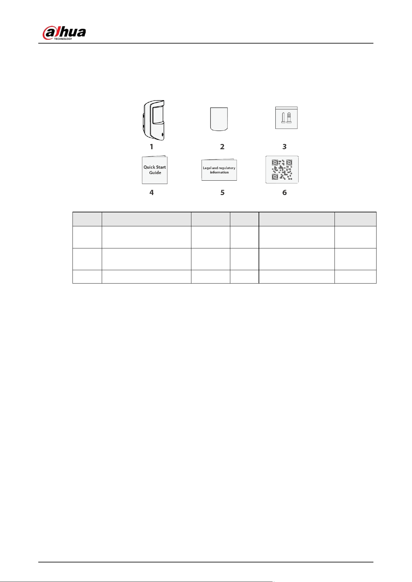
2 Checklist
Figure 2-1 Checklist
Table 2-1 Checklist
No. Item Name Quantity No. Item Name Quantity
1
Wireless dual-tech
detector
1 4 Quick start guide 1
2
Double-sided adhesive
tape
1 5
Legal and regulatory
information
1
3 Screw package 1 6 QR code 1
User’s Manual
5
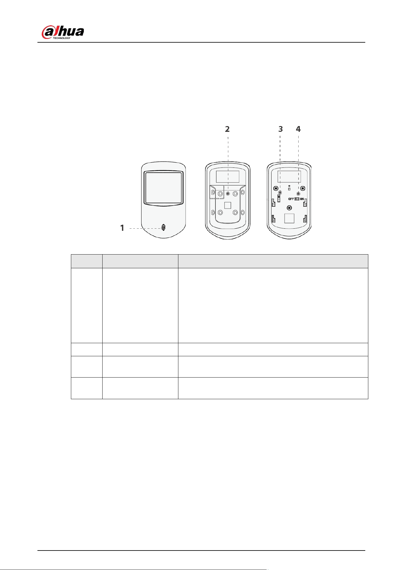
3 Design
3.1 Appearance
Figure 3-1 Appearance
Table 3-1 Structure
No. Name Description
1 Indicator
●
Flashes green quickly: Pairing mode or reduced
sensitivity mode.
●
Solid green: An alarm event was triggered.
●
Solid green for 2 seconds: Pairing successful.
●
Slowly flashes green for 3 seconds: Pairing failed.
●
Flashes green quickly for 100 seconds, and then off:
sensitivity mode.
2 On/off switch Turn on or turn off the device.
3 Tamper switch
When the tamper switch is released, the tamper alarm will be
triggered.
4 Back cover
If the back cover is opened, the tamper alarm will be
triggered.
User’s Manual
6
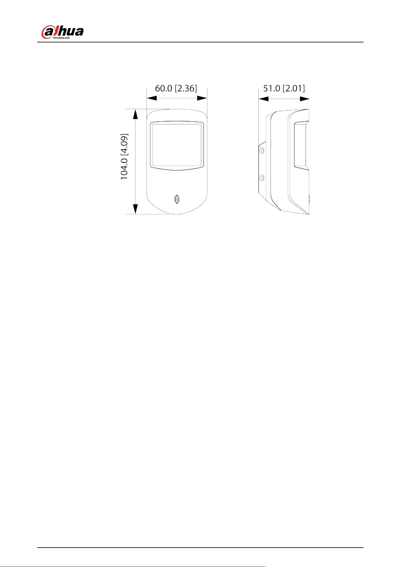
3.2 Dimensions
Figure 3-2 Dimensions (mm [inch])
User’s Manual
7
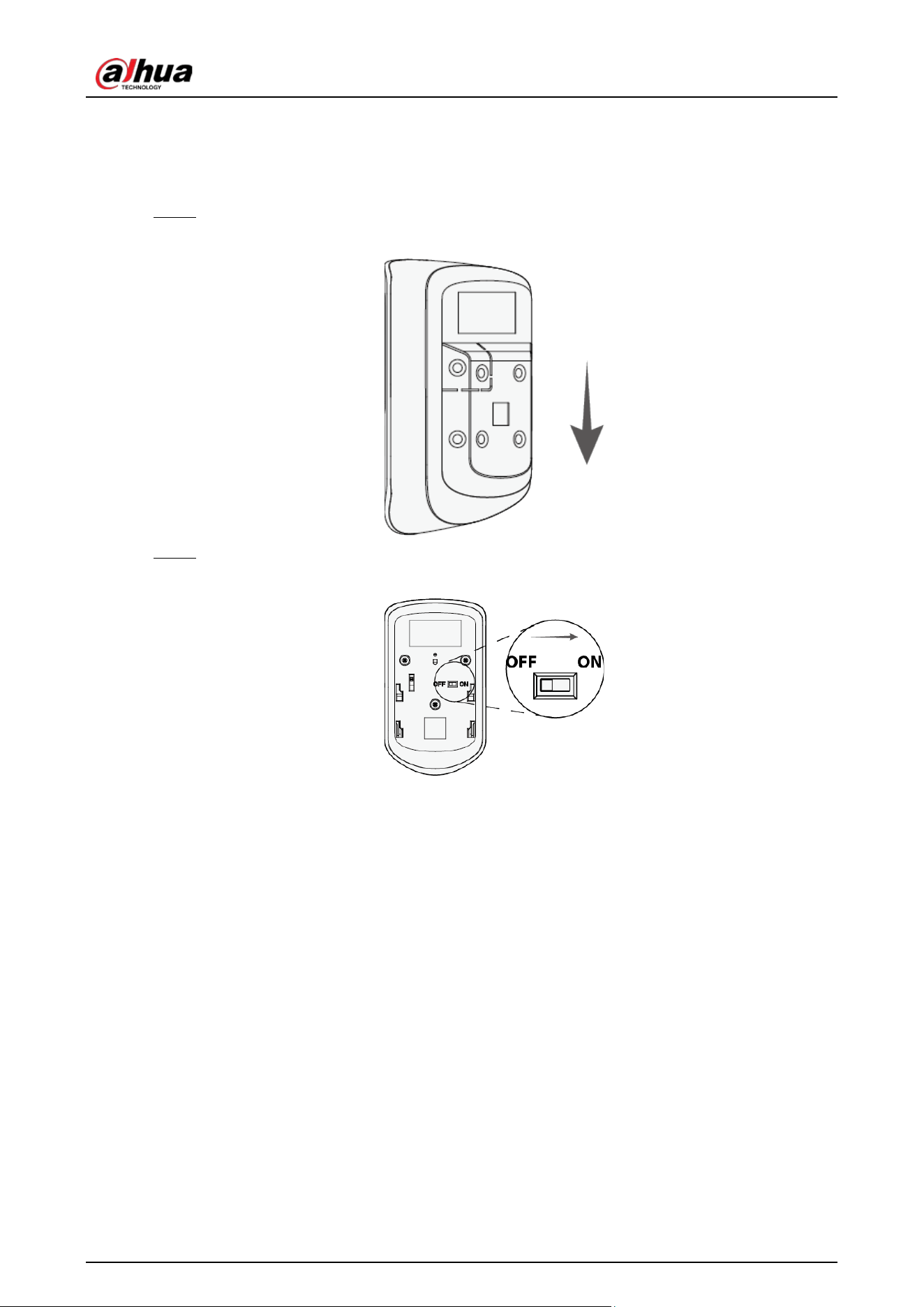
4 Power On
Step 1 Remove the back cover of the dual-tech detector.
Figure 4-1 Remove the back cover
Step 2 Turn on the dual-tech detector.
Figure 4-2 Turn on the dual-tech detector

User’s Manual
8
5 Adding the Wireless Dual-Tech Detector to the
Hub
Before you connect dual-tech detector to the hub, install the DMSS app to your phone. This manual
uses iOS as an example.
●
Make sure that the version of the DMSS app is 1.99.300 or later, and the hub is
V1.001.0000004.0.R.221030 or later.
●
Make sure that you have already created an account, and added the hub to DMSS.
●
Make sure that the hub has a stable internet connection.
●
Make sure that the hub is disarmed.
Step 1 Go to the hub screen, and then tap
Peripheral
to add the dual-tech detector.
Step 2 Tap
+
to scan the QR code at the bottom of the dual-tech detector, and then tap
Next
.
Step 3 Tap
Next
after the dual-tech detector has been found.
Step 4 Follow the on-screen instructions and switch the dual-tech detector to on, and then tap
Next
.
Step 5 Wait for the pairing.
Step 6 Customize the name of the dual-tech detector, and select the area, and then tap
Completed
.
User’s Manual
9
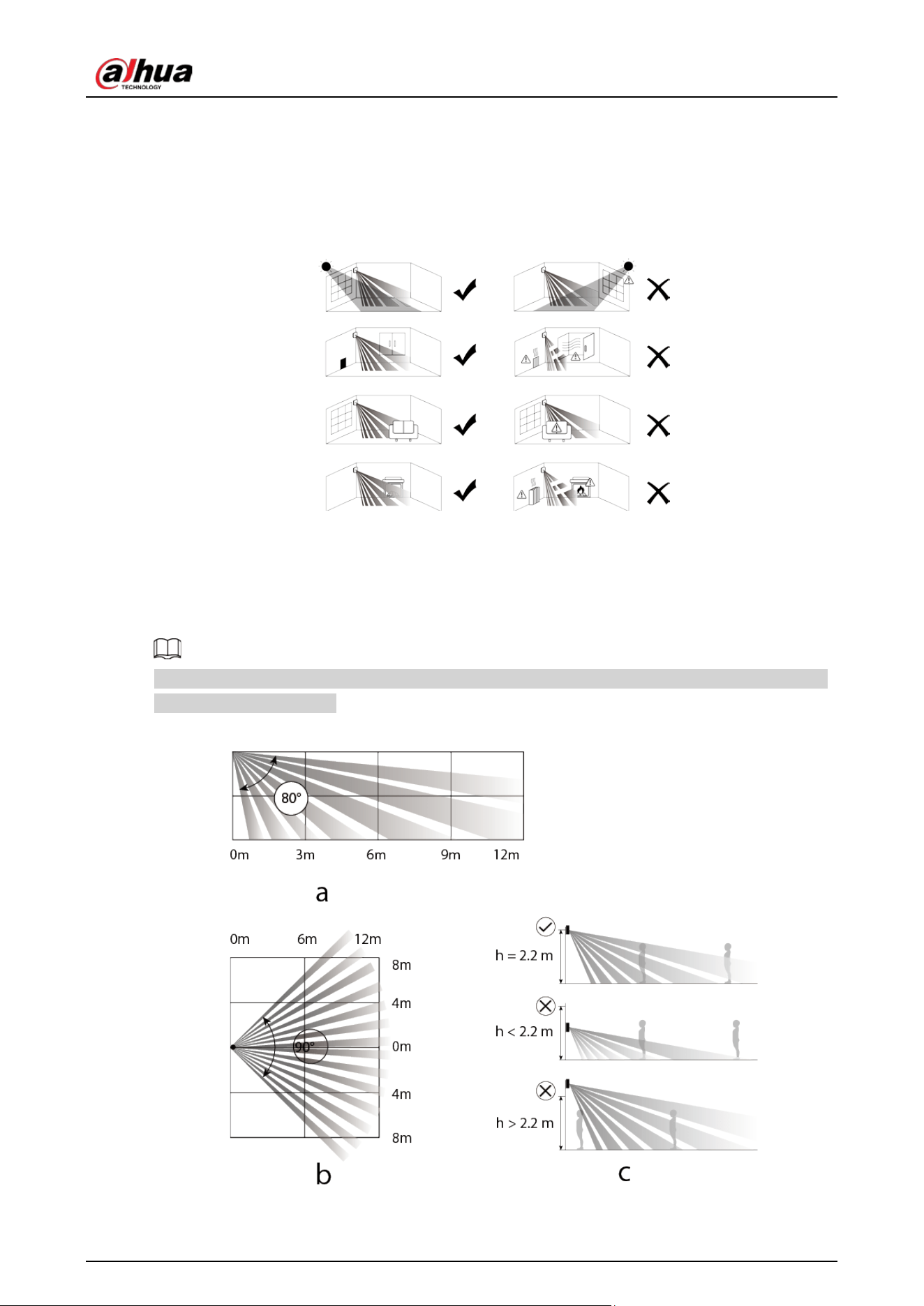
6 Installation
The dual-tech detector supports wall mount and corner mount.
Figure 6-1 Installation location
6.1 Field of View
Field of view of the dual-tech are shown below.
When installing and using the dual-tech, make sure there are no objects partially or fully obscuring
the detector's field of view.
Figure 6-2 Field of View
User’s Manual
10
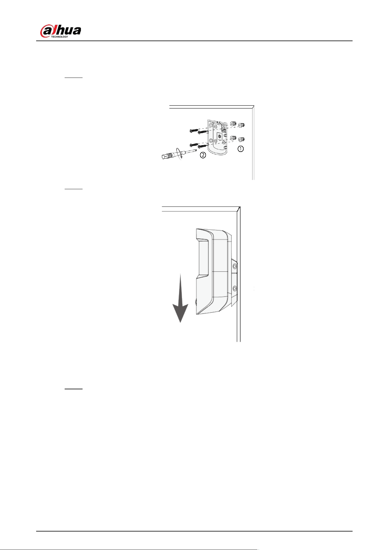
6.2 Wall Mount
Step 1 Drill 4 holes into the wall according to the hole positions of the dual-tech detector, and
then put the expansion bolts into the holes.
Figure 6-3 Drill holes
Step 2 Attach the dual-tech detector to the back cover.
Figure 6-4 Attach the detector to the back cover
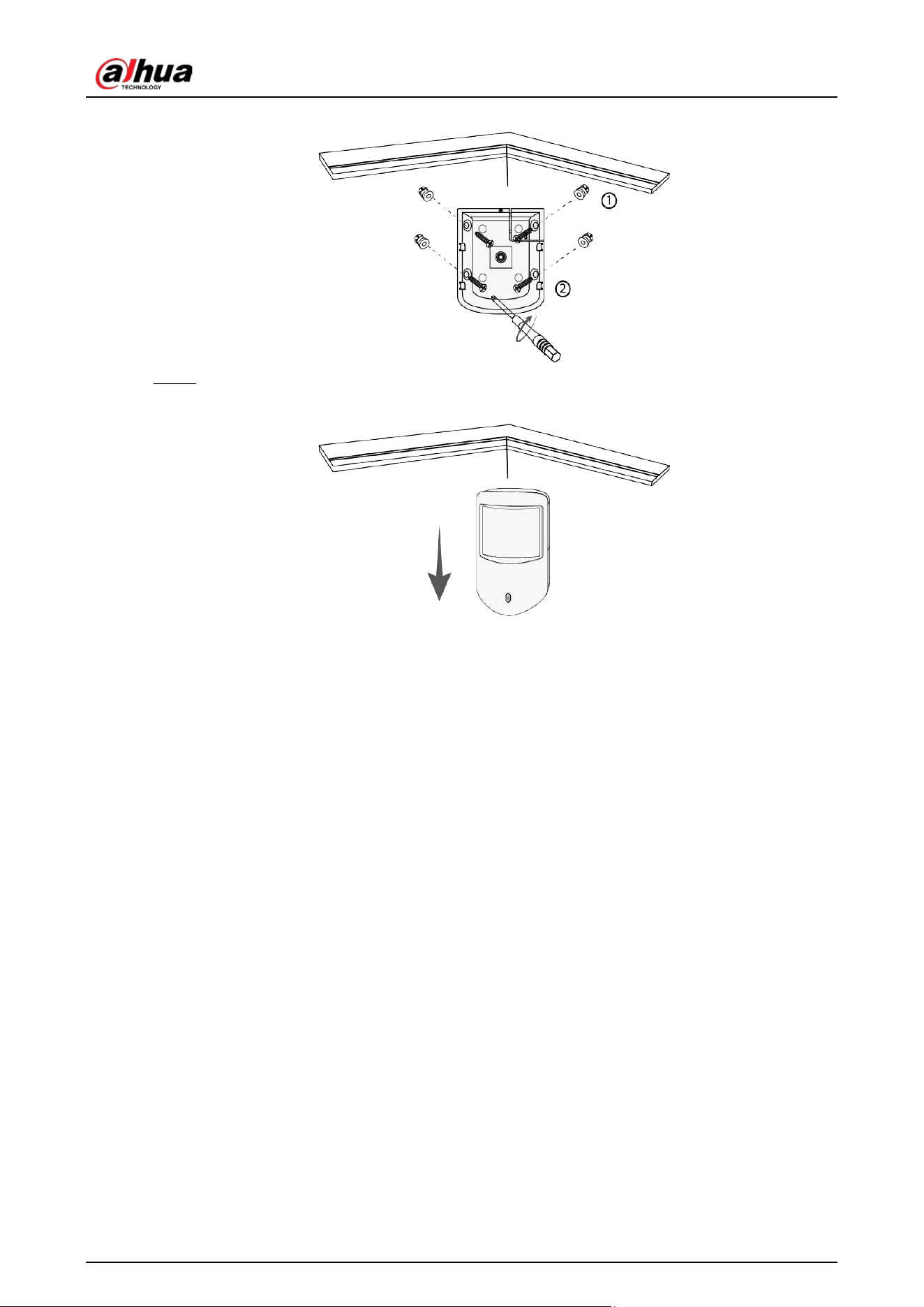
6.3 Corner Mount
Step 1 Drill 4 holes into the wall according to the hole positions of the dual-tech detector, and
then put the expansion bolts into the holes.
User’s Manual
11
Figure 6-5 Drill holes
Step 2 Attach the dual-tech detector to the back cover.
Figure 6-6 Attach the detector to the back cover
User’s Manual
12
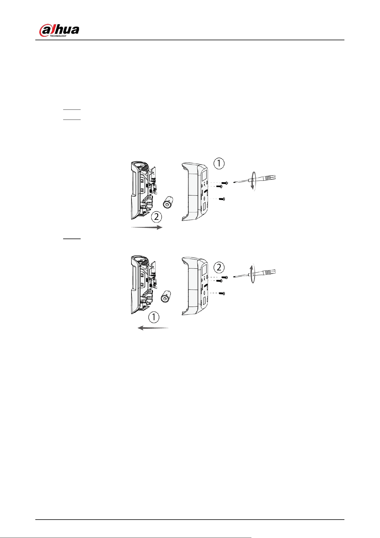
7 Replacing the Battery
The battery has been installed when leaving the factory, and the dual-tech detector can be used
directly. If the battery is dead, you need to replace the battery.
Step 1 Open the back cover of the dual-tech detector.
Step 2 Replace the battery.
When replacing the battery, make sure that the side marked with "
+
" faces the back cover
of the devices.
Figure 7-1 Replace the battery
Step 3 Close the back cover of the dual-tech detector.
Figure 7-2 Close the back cover

User’s Manual
13
8 Configuration
You can view and edit general information of the dual-tech detector.
8.1 Viewing Status
On the hub screen, select a dual-tech detector from the peripheral list, and then you can view the
status of the dual-tech detector.
Table 8-1 Status
Parameter Value
Temporary Deactivate
The status for whether the functions of the dual-tech detector are
enabled or disabled.
●
: Enable.
●
: Only disable tamper alarm.
●
: Disable.
Temperature The temperature of the environment.
Signal Strength
The signal strength between the hub and the dual-tech detector.
●
: Low.
●
: Weak.
●
: Good.
●
: Excellent.
●
: No.
Battery Level
The battery level of the dual-tech detector.
●
: Fully charged.
●
: Sufficient.
●
: Moderate.
●
: Insufficient.
●
: Low.
Tamper Status
The tamper status of the dual-tech detector, which reacts to the
detachment of the body.
Online Status
Online and offline status of the dual-tech detector.
●
: Online.
●
: Offline.
Entering Delay Time Entrance delay time.
Exiting Delay Time Exit delay time.
24 H Protection Zone
Status
Active status of the 24 h protection zone.
●
: Enable.
●
: Disable.
Sensitivity
Adjust the sensitivity level of motion detection. The higher the value,
the easier the motion is detected.
User’s Manual
14
Parameter Value
Transmit through
Repeater
The status of whether the dual-tech detector forwards its messages to
the hub through the repeater.
Program Version The program version of the dual-tech detector.
8.2 Configuring the Dual-tech Detector
On the hub screen, select a dual-tech detector from the peripheral list, and then tap to
configure the parameters of the dual-tech detector.
Table 8-2 Parameter description
Parameter Description
Device Configuration
●
View dual-tech detector name, type, SN and device model.
●
Edit dual-tech detector name, and then tap
Save
to save
configuration.
Area Select the area to which the dual-tech detector is assigned.
Temporary Deactivate
Whether send commands to the alarm hub.
●
Tap
Enable
, and then the dual-tech detector will send
commands to the hub.
Enable
is set by default.
●
Tap
Only Disable Tamper Alarm
, and then the system will
only ignore tamper alarm messages.
●
Tap
Disable
, and then the dual-tech detector will not send
commands to the hub.
LED Indicator
LED Indicator is enabled by default.
If LED Indicator is disabled, the LED indicator will remain off
regardless of whether the dual-tech detector is functioning
normally or not.
24 H Protection Zone
●
If
24 H Protection Zone
is enabled, even the system is
disarmed, the dual-tech detector can be armed and detects
motion.
●
If
24 H Protection Zone
is disabled, only when the system
is armed, the dual-tech detector can be armed and detects
motion. The dual-tech detector will not be armed
immediately, it will begin before the end of the ping
interval of the hub-detector (60 seconds by default).
You can go to the hub's screen to configure the ping
interval of the hub-detector. For details, see the user's
manual of the hub.
User’s Manual
15
Parameter Description
Home Mode
Enable the
Home Mode
, and then the selected peripherals
under the hub will be armed.
Delay Mode under Home
Mode
Enable the
Delay Mode under Home Mode
, the selected
peripheral under the hub will be armed and the alarm will not
be triggered until the end of customized delay time.
Only enable
Home Mode
first can
Delay Mode under Home
Mode
take effect.
Delay Time
The system provides you with time to leave or enter the
protection zone without alarm.
●
Delay Time for Entering Arming Mode
: When you enter
the zone, if you do not disarm the system before the delay
ends, an alarm will be triggered.
Make sure that the delay time for entering arming mode is
no longer than 45 seconds in order to comply with
EN50131-1.
●
Delay Time for Exiting Arming Mode
: When you are in the
zone and arm the system, if you do not leave the zone
before the delay ends, an alarm will be triggered. You can
select from 0 s to 120 s.
The arming mode will be effective after the delay time.
Sensitivity
●
Adjust sensitivity level of motion detection.
●
Select from low, medium and high.
Siren Linkage
When an alarm is triggered, the peripherals will report the alarm
events to the hub and alert with siren.
Alarm-video Linkage
When an alarm is triggered, the peripherals will report the alarm
events to the hub and then will link events.
Video Channel Select the video channel as needed.
Signal Strength Detection Test the current signal strength.
Detector Test
Tap
Start Detection
to test the status of the dual-tech detector.
●
The detector test will not begin immediately. it will begin
before the end of the ping interval of the hub-detector (60
seconds by default).
●
You can configure the hub-detector ping interval on the
hub.
User’s Manual
16
Parameter Description
Transmit Power
●
Select from high, low, and automatic.
●
The higher transmission power levels are, the further
transmissions can travel, but power consumption increases.
●
If you select
Low
, the dual-tech detector will enter into
reduced sensitivity mode.
●
We recommend you selecting
Low
when installing the
device to test the signal strength of the installation
location, and then adjusting to
High
or
Automatic
.
●
The indicator flashes when setting as
Low
.
User's Manual View user's manual of the device.
Cloud Update Update online.
Delete
Delete the dual-tech detector.
Go to the hub screen, select the dual-tech detector from the
peripheral list, and then swipe left to delete it.

User’s Manual
17
Appendix 1 Cybersecurity Recommendations
Cybersecurity is more than just a buzzword: it’s something that pertains to every device that is
connected to the internet. IP video surveillance is not immune to cyber risks, but taking basic steps
toward protecting and strengthening networks and networked appliances will make them less
susceptible to attacks. Below are some tips and recommendations from Dahua on how to create a
more secured security system.
Mandatory actions to be taken for basic device network security:
1.
Use Strong Passwords
Please refer to the following suggestions to set passwords:
●
The length should not be less than 8 characters.
●
Include at least two types of characters; character types include upper and lower case letters,
numbers and symbols.
●
Do not contain the account name or the account name in reverse order.
●
Do not use continuous characters, such as 123, abc, etc.
●
Do not use overlapped characters, such as 111, aaa, etc.
2.
Update Firmware and Client Software in Time
●
According to the standard procedure in Tech-industry, we recommend to keep your device
(such as NVR, DVR, IP camera, etc.) firmware up-to-date to ensure the system is equipped with
the latest security patches and fixes. When the device is connected to the public network, it is
recommended to enable the“auto-check for updates” function to obtain timely information
of firmware updates released by the manufacturer.
●
We suggest that you download and use the latest version of client software.
"Nice to have" recommendations to improve your device network security:
1.
Physical Protection
We suggest that you perform physical protection to device, especially storage devices. For
example, place the device in a special computer room and cabinet, and implement well-done
access control permission and key management to prevent unauthorized personnel from
carrying out physical contacts such as damaging hardware, unauthorized connection of
removable device (such as USB flash disk, serial port), etc.
2.
Change Passwords Regularly
We suggest that you change passwords regularly to reduce the risk of being guessed or cracked.
3.
Set and Update Passwords Reset Information Timely
The device supports password reset function. Please set up related information for password
reset in time, including the end user’s mailbox and password protection questions. If the
information changes, please modify it in time. When setting password protection questions, it is
suggested not to use those that can be easily guessed.
4.
Enable Account Lock
The account lock feature is enabled by default, and we recommend you to keep it on to
guarantee the account security. If an attacker attempts to log in with the wrong password several
times, the corresponding account and the source IP address will be locked.
5.
Change Default HTTP and Other Service Ports
We suggest you to change default HTTP and other service ports into any set of numbers between

User’s Manual
18
1024–65535, reducing the risk of outsiders being able to guess which ports you are using.
6.
Enable HTTPS
We suggest you to enable HTTPS, so that you visit Web service through a secure communication
channel.
7.
MAC Address Binding
We recommend you to bind the IP and MAC address of the gateway to the device, thus reducing
the risk of ARP spoofing.
8.
Assign Accounts and Privileges Reasonably
According to business and management requirements, reasonably add users and assign a
minimum set of permissions to them.
9.
Disable Unnecessary Services and Choose Secure Modes
If not needed, it is recommended to turn off some services such as SNMP, SMTP, UPnP, etc., to
reduce risks.
If necessary, it is highly recommended that you use safe modes, including but not limited to the
following services:
●
SNMP: Choose SNMP v3, and set up strong encryption passwords and authentication
passwords.
●
SMTP: Choose TLS to access mailbox server.
●
FTP: Choose SFTP, and set up strong passwords.
●
AP hotspot: Choose WPA2-PSK encryption mode, and set up strong passwords.
10.
Audio and Video Encrypted Transmission
If your audio and video data contents are very important or sensitive, we recommend that you
use encrypted transmission function, to reduce the risk of audio and video data being stolen
during transmission.
Reminder: encrypted transmission will cause some loss in transmission efficiency.
11.
Secure Auditing
●
Check online users: we suggest that you check online users regularly to see if the device is
logged in without authorization.
●
Check device log: By viewing the logs, you can know the IP addresses that were used to log in
to your devices and their key operations.
12.
Network Log
Due to the limited storage capacity of the device, the stored log is limited. If you need to save the
log for a long time, it is recommended that you enable the network log function to ensure that
the critical logs are synchronized to the network log server for tracing.
13.
Construct a Safe Network Environment
In order to better ensure the safety of device and reduce potential cyber risks, we recommend:
●
Disable the port mapping function of the router to avoid direct access to the intranet devices
from external network.
●
The network should be partitioned and isolated according to the actual network needs. If
there are no communication requirements between two sub networks, it is suggested to use
VLAN, network GAP and other technologies to partition the network, so as to achieve the
network isolation effect.
●
Establish the 802.1x access authentication system to reduce the risk of unauthorized access to
private networks.
●
Enable IP/MAC address filtering function to limit the range of hosts allowed to access the

User’s Manual
19
device.
More information
Please visit Dahua official website security emergency response center for security announcements
and the latest security recommendations.

User’s Manual