Loading ...
Loading ...
Loading ...
1 Parts: E
2
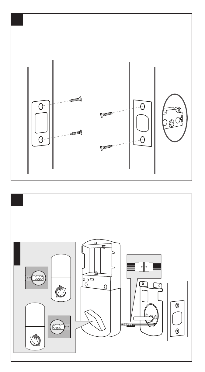
Parts: C, E, F3
UP
UP
UP
UP
Secure Strike Plate and Latch
Note: Latch should be in the UNLOCK position.
(1) Use Screws (F3) to secure Strike Plate (C) to door frame.
(2) Use Screws (F3) to secure Latch (E) To door
3
Parts: A, E
Front Module Installation
(1) Run Drive Bar (!) through the Cross Slot (!) of the Latch (E).
(2) Run Connector Wire through bore hole of door.
(!) Be sure drive bar is verticle when inserting into Cross Slot.
4
Parts: D, F1
Mounting Plate
On opposite side of door from front module:
(!) The rounded bump of the Mounting Plate (D) should be placed flush with the door.
(1) Run Drive Bar and Wire Connector through Mounting Plate (D) as shown.
(2) Use Screws (F1) to secure Mounting plate and Front Module (A).
5
Parts: B
Connect Wires
(1) Remove Battery Cover from Back Module before continuing:
(2) Connect the White Wire Tabs from the Front Module (A) and back Module (B) together.
(!) Before continuing: Back Module (B) should be in the Unlock position by twisting
thumb-turn away from Latch (E).
6
Parts: B, F2
Connect Wires
(1) Insert Drive Bar into Back Module’s (B) Cross Slot.
(2) Secure with Screws (F2).
(3) Install brand new 4x AA batteries
(4) Place battery cover back on.
UP
Adjusting Latch Size
For doors with bore holes 2 3/8” (60mm) from door edge, do not extend latch.
For doors with bore holes 2 3/4” (70mm) from door edge, extend latch by:
(1) Twist Latch
(2) Extend
(3) Twist back
(Note: When inserting into door, be sure UP↑ on latch is correctly oriented)
DOOR DOOR
2 3/4” (70mm)2 3/8” (60mm)
LATCH NOT EXTENDED LATCH EXTENDED
Cross Slot
Drive Bar
!
!
Mounting
Plate
Door
1
C
S
2
1
C
S
2
!
UP
Both Latch (E) and Back
Module (B) is in the
Unlock Position
1
C
S
2
** Illustrations may not be exact representation of product. Does not effect installation.
** Illustrations may not be exact representation of product. Does not effect installation.** Illustrations may not be exact representation of product. Does not effect installation.
Loading ...