Loading ...
Loading ...
Loading ...
WARNING – SERVICING TO BE CARRIED OUT ONLY BY AN AUTHORISED PERSON
Disconnect from electricity before servicing. Check appliance is safe when you have nished.
33
A
B
A
B
C
ArtNo.311-0010 n ectors
4 Ovens
4.1 To Remove the Oven Inner Back
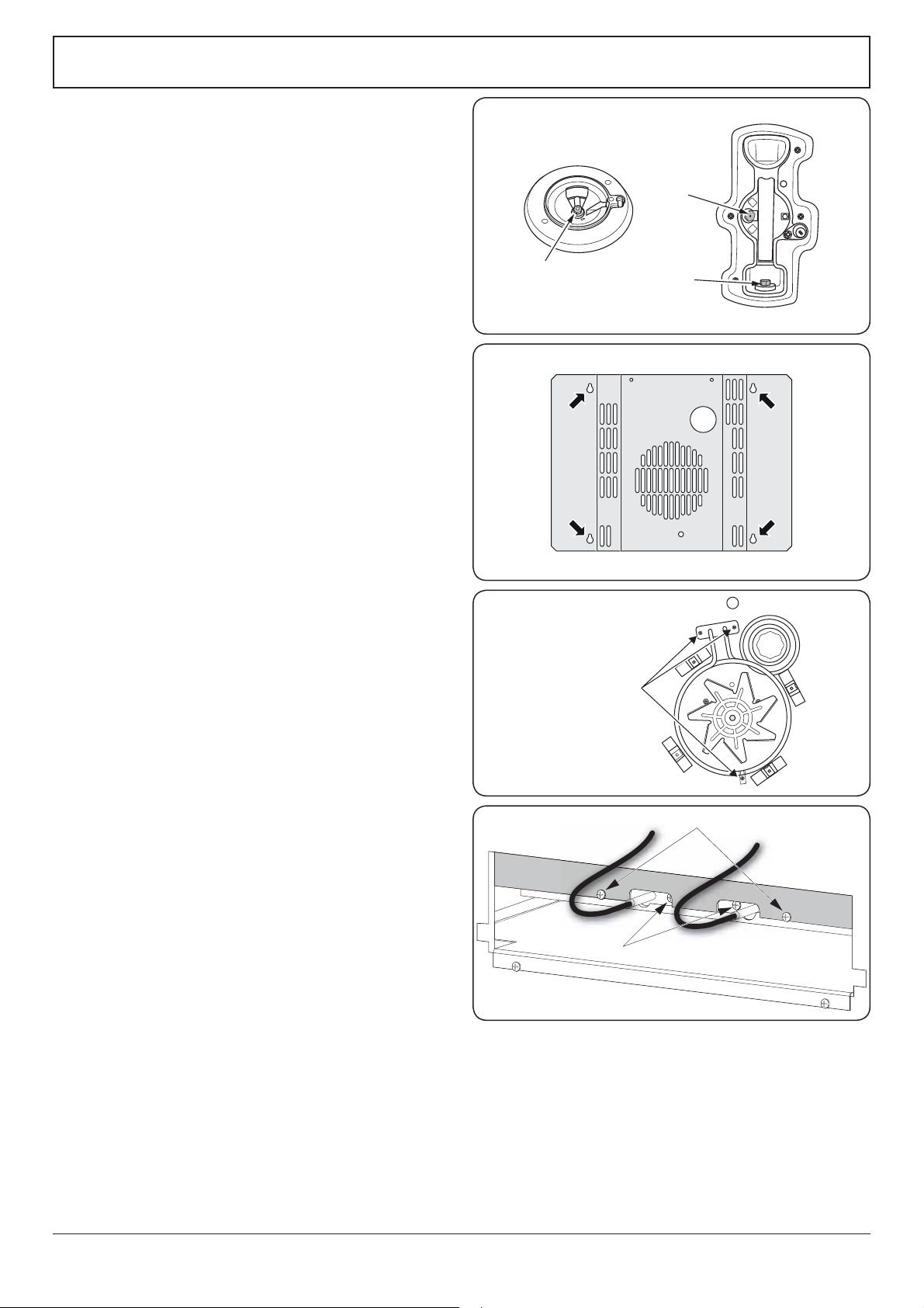
Main Oven Only
Open the main oven door. Remove the 4 screws and
washers securing the inner back to the back of the oven
(Fig. 9.3). Carefully lift away the inner back.
Reassemble in reverse order, making sure that you fully
tighten the 4 screws and washers.
4.2 To Change the Oven Fan
n
DISCONNECT FROM THE ELECTRICITY SUPPLY.
Pull the cooker forward to gain access to the rear.
Remove the screws securing the electric cover to the
back sheet and remove the cover. Disconnect the
3terminals connected to the fan, noting their position.
Remove the oven inner back (see 4.1). Hold the fan
blade and remove the centre nut (left-hand thread),
2 brass washers, fan blade and circlip. Unscrew the fan
retaining nuts and washers (3 o each) and lift the fan
away from the rear of the cooker.
Fit the new fan and reassemble in reverse order. Check
the operation of the oven.
4.3 To Replace a Fan Oven Element
n
DISCONNECT FROM THE ELECTRICITY SUPPLY.
Remove the oven inner back (see 4.1).
Remove the 2 screws from the top of the element and
the 1 from the bottom of the element (Fig. 9.4).
Carefully lift the element out, disconnecting the
terminals connected to the element (noting their
positions).
If it is not possible to disconnect the leads in this way,
pull the cooker forward to gain access to the rear,
remove the screws securing the electric cover to the
back sheet, remove the cover and disconnect the
terminals from the rear.
Fit the new element and reassemble in reverse order.
Check the operation of the oven.
4.4 To Replace the Main Oven Bottom and Top Elements
n
DISCONNECT FROM THE ELECTRICITY SUPPLY.
Bottom Element
Pull the cooker forward to access the cover boxes at
the rear of the unit. Remove the xings that secure the
cover and lift it clear.
Remove the 2 screws ‘A’ and allow the plate to drop
down (Fig. 9.6). Remove the 2 screws ‘B’, lift element
and remove through the slot in the range back
(Fig. 9.6). Undo the terminal connections, noting their
positions. Withdraw the element.
Replace the element and re-assemble parts in reverse
order.
Fig. 9.3
&MFNFOUmYJOHTDSFXT
ArtNo.321-0005 Fan oven element
Fig. 9.4
Fig. 9.5
Fig. 9.6
Standard burner
A – Injector, B – Internal injector, C – External injector
Loading ...
Loading ...
Loading ...