Operation, Installation & Maintenance Manual
THANK YOU FOR PURCHASING
THIS CENTRAL AIR CONDITIONER.
PLEASE READ AND UNDERSTAND
THIS MANUAL BEFORE USING THE
AIR CONDITIONER. KEEP THIS
MANUAL FOR FUTURE
REFERENCE.
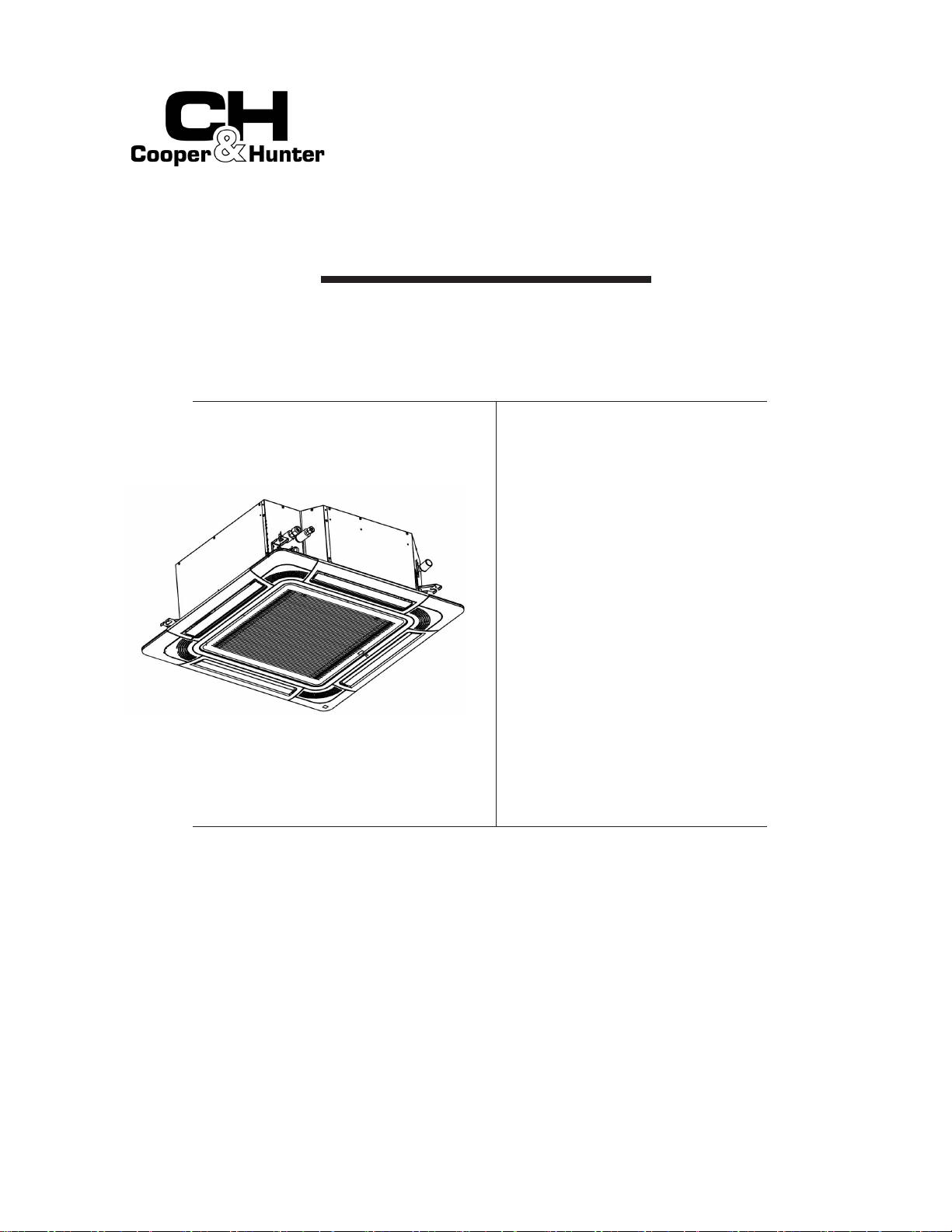
4-WAY CASSETTE TYPE
ORIGINAL INSTRUCTIONS
CHV-09SCC4W
CHV-12SCC4W
CHV-15SCC4W
CHV-19SCC4W
CHV-22SCC4W
CHV-24SCC4W
CHV-27SCC4W
CHV-30SCC4W
CHV-38SCC4W
CHV-48SCC4W
CHV-54SCC4W

Dear user:
Thank you for choosing and using our product. To better understand and use this product, please be sure to read
and observe the following related issues before use.
This manual should be considered as a permanent part of the air conditioning equipment. Please keep it
properly.
Our company pursues a policy of continuous improvement in design and performance of products. The right is
therefore reserved to change specifications without notice.
Our company shall not be held responsible for any occasional damage to the air conditioner that arises during
its operation in specific environment. This air conditioner is designed for standard air conditioning only. Do not
use it for other purposes such as drying cloth, refrigerating foods or for any other cooling or heating processes.
Please don't install the air conditioner in the following environments. Otherwise, fire, machine deformation or
failure may arise.
Places with spatter of oil (including machine oil).
Places with inflammable gases.
Places with sulfurated gases or silicon (e.g. hot spring, etc.).
Coastal areas with much salt or places exposed to strong
acids or bases that may cause corrosion to machine.
IMPORTANT NOTICE
Signal words (DANGER, WARNING and CAUTION) are used to indicate hazard seriousness. Definitions of
the hazard levels are provided below with respective signal words.
This heat pump air conditioner has been designed for the following temperatures. Be sure to operate the heat
pump air conditioner within this range.
Do not have the air outlet directly faced towards animals or plants, since this may bring about an adverse effect
thereon.
The installation and service engineering have to comply with local standards, laws and regulations.
As an "appliance inaccessible to the public", the installation height of indoor unit of the air conditioner shall be
at least 8.2ft.(2.5m).
This air conditioner can only be installed by dealers or professionals. The installation by user may lead to water
leakage, electric shock or fire.
In case of any question, please consult the dealer or the service center designated by our company.
For environmental protection, please don't dispose of the product casually. Our company can provide recycling
service based on relevant regulations, and provide replacement parts according to t tdd.
This temperature may vary with outdoor unit.
DB: Dry Bulb, WB: Wet Bulb
DANGER
: Immediate hazard that WILL result in severe personal injury or death.
: Hazards or unsafe practices that COULD result in severe personal injury or death.
: Hazards or unsafe practices which COULD result in minor personal injury or damage to
property damage.
: Useful information for operation and/or maintenance.
Refer
to the instruction manual for complete machine (outdoor unit) for information about the product
standards to which the indoor unit is subject.
Temperature
Cooling
Operation
Indoor
Maximum
9
o
F DB/73
o
F WB(32
o
C DB/23
o
C WB)
Minimum
o
F DB/59
o
F WB(21
o
C DB/15
o
C WB)
Outdoor 110
o
F DB (43
o
C DB) *
Heating
Operation
Indoor
Outdoor
80
o
F DB (27
o
C DB)
23
o
F DB (-5
o
C DB) *
59
o
F DB ( 15
o
C DB)
-4
o
F WB (-20
o
C WB) *
9
o
F WB (
o
C WB) *

Refrigerant R410A is non-flammable, non-toxic, and odorless, and may produce toxic gases when exposed to
open flame. Since this refrigerant gas is heavier than air, it may result in lack of oxygen, thereby leading to
breathing difficulties when the area near the ground is filled with this gas. If that's the case, please turn off the
main switch immediately, cut off the power supply, and open the doors and windows for ventilation. Put out any
open flame, and contact your service dealer. Performing leak detection and gas tightness test with oxygen,
acetylene or other flammable and toxic gases may cause explosion, so nitrogen is recommended for this test.
The standards for safe refrigerant leakage in construction and system operation are determined based on local
regulations or standards.
Use ELB with medium or higher sensing speed (ELB with an operating time of 0.1 seconds or less), or
electric shock or fire may arise.
For installation, the refrigerant piping must be firmly connected before the operation of compressor. For repair,
the refrigerant piping must be moved, handled and removed after the stop of compressor.
Please don't short-circuit the protective device (e.g., the pressure switch, etc.) during operation, since this
may cause fire or explosion.
Do not use any sprays such as insecticide, lacquer, hair spray or other flammable gases within approximately
one 3.3ft.(1m) from the system.
If the earth leakage breaker (ELB) is frequently activated, please stop the system and contact your local dealer
or customer services.
Make sure the ground wire is securely connected. The improper grounding of machine may lead to electrical
failure. Please don't connect the ground wire to gas pipes, tap water pipes, lightning rods or phone ground
wires.
Make sure there are no flammable materials around during brazing operation. Please wear leather gloves to
prevent frostbite when filling refrigerant.
Prevent rats or other small animals damaging the wiring and electrical components. Bitten unprotected parts
may cause a fire.
Firmly fix the connection wires. The external force of terminal may result in looseness of terminal that may
cause a fire.
Make sure the air conditioner is installed with enough strength of fixation; otherwise, the air conditioner may
fall or topple over, which may bring about machine damage or personal injury.
Please follow the installation instructions and related regulations and standards for electrical construction;
otherwise, electrical failure or fire may occur due to inadequate capacity or inconsistent specifications.
Never fail to use specified wiring and select correct wiring, since failure to do so may cause electrical failure or
fire.
Please make sure the outdoor unit is not covered with snow or ice before use.
Please don't perform installation works such as refrigerant piping connection, drain pipe connection, and
wiring connection. Violations may result in system leakage, electrical failure or fire. In the case of fire, please
turn off the power immediately; please don't touch electrical parts with the hands, or electric shock may arise.
Do not pour water into the indoor or outdoor unit. This machine is an electric product that may develop
serious electric failure when exposed to water.
Do not open the service cover of indoor or outdoor units without turning OFF the main power supply;
otherwise, this may bring about serious safety accident.
Do not touch or adjust safety devices inside the indoor or outdoor units. If they are touched or readjusted,
serious accident may arise.
DANGER
The A-weighted emission sound pressure level at workstations, where this exceeds 70 dB(A).
This appliance can be used by children aged from 8 years and above and persons with reduced physical,
sensory or mental capabilities or lack of experience and knowledge if they have been given supervision or
instruction concerning use of the appliance in a safe way and understand the hazards involved. Children shall not
play with the appliance
. Cleaning and user maintenance shall not be made by children without supervision.

CHECKING PRODUCT RECEIVED
Upon receipt of this product, check it for any shipping damage.
Claims for damage, either apparent or concealed, should be filed immediately with the shipping company.
Check the model number, electrical parameters (power supply, voltage, and frequency) and accessories to
determine if they are correct. Please contact your local dealer in case of problem.
Our company shall not be held responsible for any consequence arising from the modification to equipment
without our written consent.
Correct Disposal of this product
This marking indicates that this product should not be disposed with other
household wastes. To prevent possible harm to the environment or human
health from uncontrolled waste disposal, recycle it responsibly to promote the
sustainable reuse of material resources. To return your used device, please use
the return and collection systems or contact the retailer where the product was
purchased. They can take this product for environmental safe recycling.


1.Safety Precautions
Installation of Indoor Unit
4.1 Factory-Supplied Accessories
4.2 Initial Check
4.3 Installation
Refrigerant Piping Work
5.1 Piping Materials
5.2 Piping Connection
8.Test Run
9.Protection Control Devices
10.Field Operation
Electrical Wiring
7.1 General Check
7.2 Wiring
7.3 Field Wire Size for Power Source Line
2.
4.
5.
6.Drain Pipe
Tools & Instruments for Installation
Transportation & Handling
3.1 Transportation
3.2 Handling of Indoor Unit
3.
7.
10.1 Setting of DIP Switch
10.2 Setting of Fan Speed


Note: When in immediate contact with refrigerant, please use the installation tools and instruments dedicated to the new refrigerant.
Do not perform installation work, refrigerant piping
work, drain piping and electrical wiring connection
without referring to the installation manual.
Check that the ground wire is securely connected.
Connect a fuse of specified capacity.
Do not install the indoor unit, outdoor unit,
remote control switch and cable
within approximately 9.8ft.(3m) from strong
electromagnetic wave radiators such as
medical equipment.
1
2
3
4
5
6
7
8
9
10
11
12
13
14
15
16
17
18
19
20
No.
Tool
Handsaw
Screwdriver
Vacuum Pump
Refrigerant Gas Hose
Megohmmeter
Copper Pipe Bender
Water Pump
Pipe Cutter
Brazing Kit
Hexagon Wrench
Tool
Spanner
Charging Cylinder
Multi-purpose Measuring Instrument
Cutter for Wires
Gas Leak Detector
Leveller
Clamper for Solderless Terminals
Hoist (for Indoor Unit)
Ammeter
Voltage Meter
No.
Do not put any foreign material into the indoor unit
and check to ensure that none exists in the indoor
unit before the installation and test run. Otherwise, a
fire or failure, etc. may occur.
Be careful not to cause damage to insulation
materials of the unit surface when it's lifted.
Transport the product as close to the installation
location as practical before unpacking.
3.1 Transportation
Since the pressure of new refrigerant R410A is 1.4 times that of traditional refrigerant, its performance is
susceptible to impurities like moisture, scale and grease, etc. It's essential to remove the moisture, dust, other
refrigerants or refrigerant oils from the refrigeration system. Hence, the failure to use specified materials and
tools may result in explosion, personal injury, refrigerant leakage, electrical failure or fire.
Do not put any material on the product.
3.2 Instructions for Handling
Install the indoor unit as per national standard
Do not install the indoor unit in a flammable
environment since this may cause fire or an explosion.
4.1 Factory-Supplied Accessories
Check to ensure that the accessories are packed
with indoor unit.
Please refer to the packing list on the end page of
this manual for standard accessories.
If any of these accessories are not packed with the
unit, please contact your dealer.
Do not install the indoor unit outdoors. If installed
outdoors, an electric hazard or electric leakage will
occur.
1

4.2 Initial Check
To avoid any corrosive action to the heat
exchangers, do not install the indoor unit in
an acid or alkaline environment.
4.3 Installation
4.3.1 Opening of False Ceiling and Suspension Bolts
Install the indoor unit in a space for easy operation
and maintenance as shown in Fig. 4.1.
Provide a service access door near the unit
piping connection area on the ceiling.
Check to ensure that the ceiling is strong
enough to hang the indoor unit.
Check if the ceiling surface is flat for the air
panel installation.
(1) Select appropriate location and direction for installation
of indoor unit, and determine its location. Pay careful
attention to the space for the piping, wiring and
maintenance.
Fig. 4.1 Space around Indoor Unit
The indoor unit must be installed at an appropriate
location so that the indoor temperature can be evenly
distributed.
There should be no obstruction of air flow at the vent.
Select the installation location as follows:
(A) Minimum Space
(B) Down Slope
Pitch of Drain Pipe: 1/25~1/100
Do not install the indoor unit in a machinery shop
or kitchen where vapor from oil or its mist flows
to the indoor unit.
Once the oil deposits on the heat exchanger, it
may impair the performance of indoor unit and
cause damage to plastic parts therein.
Pay attention to the following points when the
indoor unit is installed in a hospital or other
facilities where there are electronic waves from
medical equipment, etc.
(A) Do not install the indoor unit where the
electromagnetic wave is directly radiated to the
electrical box, remote control cable or remote
control.
(B) Install the indoor unit and components as far as
practical or at least 9.8ft.(3m) from the
electromagnetic wave radiator.
(C) Install the remote control switch in an iron box.
Arrange the remote control cable in an iron
tube. Ground the iron box and iron tube.
(D) Install a noise filter when the power supply emits
harmful noises.
Fig. 4.2 Installation Location of Indoor Unit
Fig. 4.3 Opening of False Ceiling and Suspension
Bolts
(3) Ensure that the ceiling is horizontally level;
otherwise, proper drainage flow would be impossible.
(4
)
Strengthen the opening parts of the ceiling.
(5) Mount suspension bolts, as shown in the figure.
Drain Pipe
1/25~1/100 Down Slope
2
Piping Connection
Service Access
Door ≥ 2332.(mm)
Service Access
Door ≥ 2332.(450mm)
Piping Connection
Piping Connection
Service Access
Door ≥ 2332.(mm)
Distance from Wall Side
Service Space
Piping Connection
2232.(10~20 mm)
92.(260 mm)
22.(310 mm)
Indoor Unit Height in Ceiling
●
The figure on the right shows the sensing area of
motion detector when the motion detector in
panel is in service.
Motion detector
2.6ft.(0.8m) above the ground
Approx. 9.ft.(6m)
Approx. 28.9ft.(m)
a
8.2ft.(2.5m)
.ft.(m)
299()
Suspension Bolts
4 location of Suspension Bolts
299(760)
(Dimension of Suspension Bolts)
33(840
(Dimension of Indoor Unit)
860-910
(Dimension of Opening )
0
()
≥4.9ft.
(1.5m)
≥4.9ft.
(1.5m)
≥4.9ft.
(1.5m)
≥4.9ft.
(1.5m)
≥4.9ft.
(1.5m)
≥4.9ft.
(1.5m)
≥4.9ft.
(1.5m)
≥9.8ft.(3m)
≥4.9ft.
(1.5m)
≥4.9ft.
(1.5m)
≥2932.
(mm)
3.(mm)
3.(mm)
9.(mm)
9.(mm)
3938.(mm)
mmt
232(2)
232(2)
232(2)
232(2)
(Dimension of Suspension Bolts)
.(mm)
(mf)
3333(89)
33(8)
(mfdt)
≥4.9ft.
(1.5m)
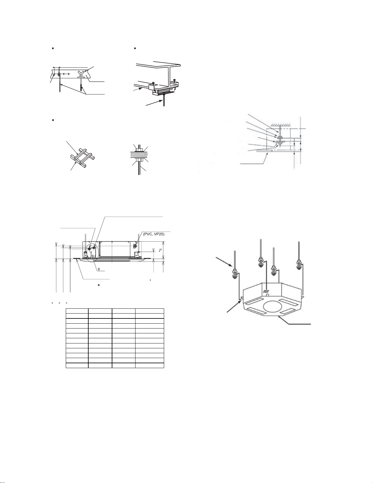
Fig. 4.4 Mounting the Suspension Bolts
4.3.2 Connection Points of Suspension Bolts and Pipes
4.3.3 Mounting the Indoor Unit
Mount the indoor unit as shown in Fig. 4.6.
Mount field-supplied parts
Suspension bolt 4-M10 or W3/8
Nut 8-M10 or W3/8
Washer 8-M10 or W3/8
(1) Mount nuts and washers to the suspension bolts.
Fig. 4. Mounting the Indoor Unit
For Concrete Slab
For Steel Beam
Suspension Bolt
(W3/8 or M10)
Fixing Point
Beam
Suspension Bolt
(W3/8 or M10)
For Wooden Beam
Suspension Wooden Rib
(223.(60mm) to
33.(90mm)
lumber)
Wooden Beam
(2) Lift the indoor unit by hoist, and do not
put any force on the water pan.
(3) Secure the indoor unit using the nuts and
washers.
Note: If a false ceiling has already been
installed, be sure to complete all piping and
wiring works inside the ceiling before
hooking-up the indoor unit.
Nut
Square Washer
Suspension Bolt
Nut
Square Washer
Suspension Bolt
Suspension Bracket
Water Pan
Fig. 4.6 Mounting Nuts and Washers
Suspension Bolt (Field Supplied)
Nut (Field Supplied)
*
Insulating Washer
(Accessory)
Bracket (for Fixing Indoor Unit)
Washer (Accessory)
Nut (Field Supplied)
Surface of Ceiling
Approx. 2(50)
Approx. 2(50)
*
Mount the washer with its insulating surface
facing down
Fig. 4.5 Mounting Suspension Bracket
3
4-21/64()
4-21/64(110)
1-3/16(30)
Drain Pipe
Surface of Ceiling
2932(150) (Gas Pipe)
3(167) (Liquid Pipe)
(1 (
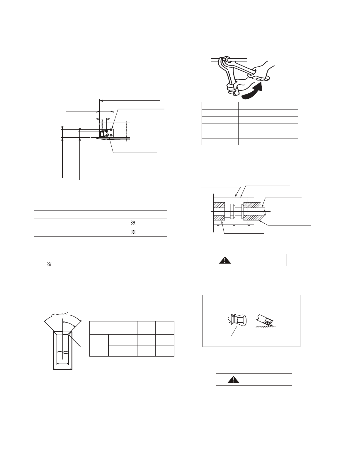
Confirm the distance between the bottom surface
of indoor unit and the surface of ceiling.
Pipe
Pipe
5-29/32~6-19/64in.(150~160mm)
Screw in
220~331lbs(100~150kg)
Concrete
in.(mm)
3(3)
unit(kBTU) a b c
09
1/2(12.7)
1/4(6.35)
10-15/64(260)
12
1/2(12.7)
1/4(6.35)
10-15/64(260)
15
1/2(12.7)
1/4(6.35)
10-15/64(260)
19
1/2(12.7)
1/4(6.35)
10-15/64(260)
22
1/2(12.7)
1/4(6.35)
10-15/64(260)
24 5/8(15.88) 3/8(9.53) 10-15/64(260)
27 5/8(15.88) 3/8(9.53) 12-13/64(310)
30 5/8(15.88) 3/8(9.53) 12-13/64(310)
38 5/8(15.88) 3/8(9.53) 12-13/64(310)
48 5/8(15.88) 3/8(9.53) 12-13/64(310)
54 5/8(15.88) 3/8(9.53) 12-13/64(310)
in.(mm)
in.(mm)

Use refrigerant R410A in the refrigerant cycle. Do not
charge oxygen, acetylene or other flammable and
poisonous gases into the refrigerant cycle when
performing a leakage test or an air-tight test. These
gases are extremely dangerous and can cause an
explosion. It is recommended nitrogen be used for
those tests.
4.3.4 Adjust the Distance between Indoor Unit
5.1 Piping Materials
(1) Prepare locally-supplied copper pipes.
(2) Select clean copper pipes. Make sure there is no
dust and moisture inside. Blow the inside of the
pipes with nitrogen or dry air, to remove any dust
or foreign matters before connecting pipes.
(3) Select copper pipes based on Fig. 5.2.
4. Mounting Indoor Unit
(2) Adjust the indoor unit to the correct position
(a) For suspended ceiling with panel installed
(b) For ceiling without panel
Installation Details for Air Panel
The details of installation work for air panel
shall be according to the Installation Manual.
Check to ensure the proper connection of
connectors between the indoor unit and air
panel.
Flange Surface
Indoor Unit
(Bottom View)
Ceiling
Indoor Unit
Surface of
Suspended
Ceiling
Suspension Bolt
Surface of Ceiling
Indoor Unit
Bolt (M6)
Pattern Board for Installation
(0~)
(0~)
21/64~1-3/8
(0~)
(0~)
using the factory-supplied inspection ruler
and Ceiling
Put the inspection ruler
below the indoor unit
Put the inspection ruler at
surface of suspended ceiling
Opening size of inspection ruler
Check the heights of suspended ceiling and
indoor unit at each corner
Check the size of each side
(1) The pattern board for installation is in the
packing carton. Please cut it off.
Please cover the machine with plastic cloth
to keep it clean during installation.
Check the level of water pan using a water
level to avoid incorrect installation of drain
discharge mechanism.
The drain pipe side must be approximately
5mm lower than other parts.
Tighten the nuts of the suspension brackets
after the adjustment is completed. Apply
LOCK-TIGHT paint to the bolts and nuts in
order to prevent them loosening. Otherwise,
abnormal noise or sounds may occur and the
indoor unit may fall down.
4
55/64(22)
Opening Size
Opening Size
21/64~1-3/8
21/64~1-3/8
21/64~1-3/8
in.(mm)
Unit Side
(Field-Supplied)
Insulating Pipe
(Field-Supplied)
Cord Clamp
(Factory-Supplied)
Insulating Pipe
(Field-Supplied)
Refrigeration Piping
Fig. 5.1 Pipe Connection Points
Fig. 5.2 Pipe Diameter
Since the nut cap connected at gas pipe is
designed exclusively for R410A, the piping flaring
connected for off-factory installation is adjusted as
compared with R22 and R407C. Please perform
the processing operation based on the dimensions
shown below: (See Fig. 5.3)
(2) As shown in Fig. 5.4, two spanners shall be used for
Insulating Pipe
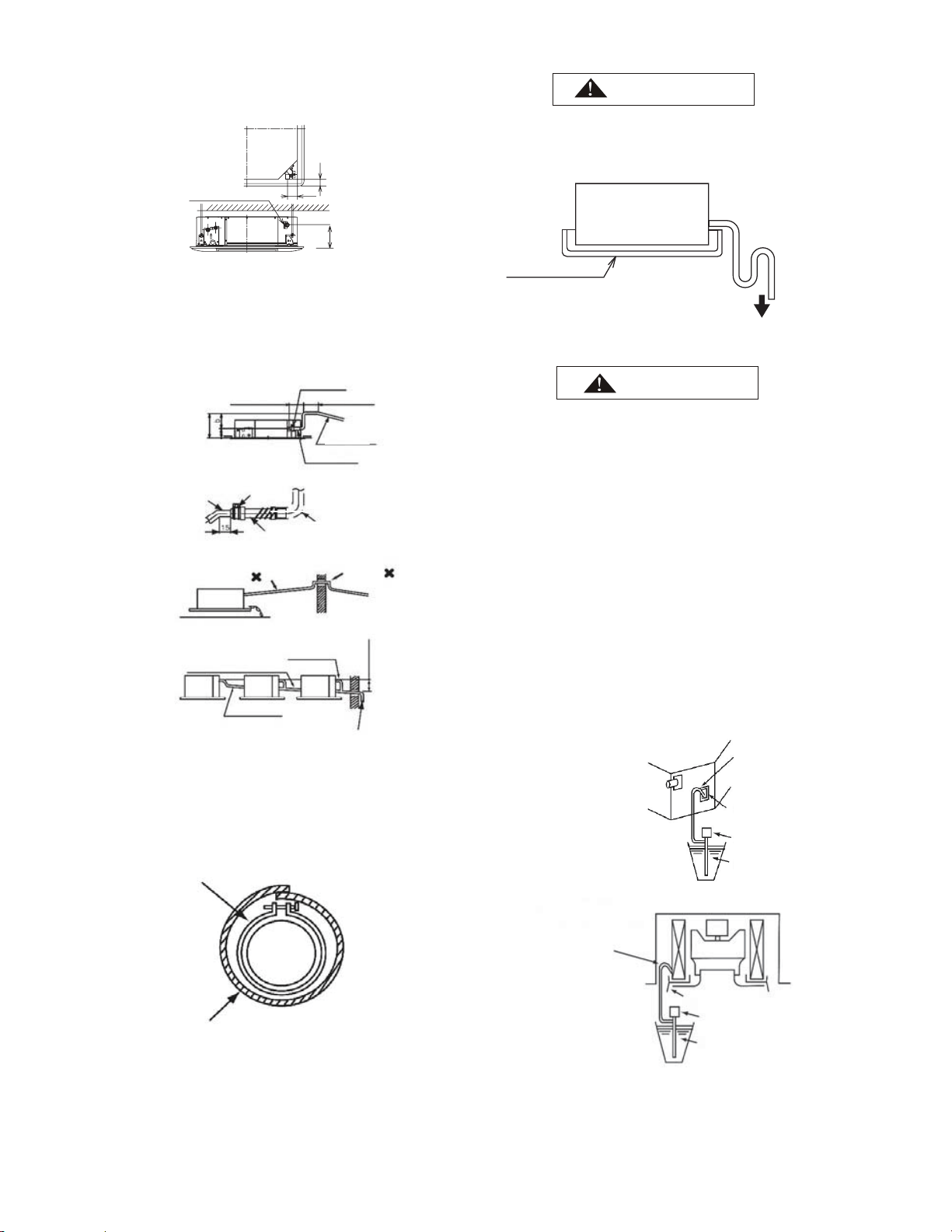
Cap the end of the pipe when the pipe is to
penetrate a hole.
Do not put pipes on the ground directly without a
cap or vinyl tape arranged at the end of the pipe.
Do not put pipes on the ground directly
Correct
Incorrect
Blocked with Tape or Plug
(4) Discharging and Charging Refrigerant
Follow the Installation & Maintenance Manual for
outdoor unit.
Excessive and inadequate refrigerant is a leading
cause of system anomaly.
Please inject the right amount of refrigerant.
Pipe Size.(mm)
TighteningTorque ft·(N.m)
10.3~13.3(14~)
29.5(40)
44.3(60)
48.7~56.8(63~77)
Outside Diameter of
Piping (a)
Outside
Diameter
of Flaring
(D)
R410A
21/32
(16.6)
25/32
(19.7)
Unit: in. (mm)
1/2
5/8
(Φ12.7)
(Φ15.88)
Fig. 5.3 Flaring
5.2 Piping Connection
Fig. 5.4 Nut tightening torque
(3) Insulate the refrigeration piping with field-
supplied insulating pipe upon completion of
refrigerant pipe connection. See Fig. 5.5.
Fig. 5.5 Insulation on Pipes
90
0
±2
0
45
0
R0.4~0.8
a
D
0
-0.4
±2
0
●
●
(1) The connection point and diameter of piping
are shown in Figs. 5.1 and 5.2.
Unit: in.(mm)
73.8(100)
5
Gas Pipe
Liquid Pipe
Capacity of indoor unit(kBtu/h)
1/2(Φ12.7)
5/8(Φ15.88)
1/4(Φ6.35)
3/8(Φ9.53)
09~22
24~54
R22、R407C
41/64
(16.2)
49/64
(19.4)
5-29/32(150) (Connected to
Gas Pipe)
6-37/64(167) (Connected to
Liquid Pipe)
33-5/64(0) ( )
6-19/64(160) (Liquid Pipe)
3-47/64(9) (Gas Pipe)
5/8(Φ15.88)
1/2(Φ12.7)
3/8(Φ9.53)
1/4(Φ6.35)
3/4(Φ19.05)
Unit: in.(mm)
Where the relative humidity of air inlet or
ambient air exceeds 80%, an auxiliary water pan
shall be fabricated at installation site and placed
under the indoor unit, as shown in Fig. 6.2.
Indoor Unit
Water Outlet
Condensate Pan
Field-Supplied
Fig. 6.2 Auxiliary Water Pan
a.Turn on the power.
b.
Fill the water pan with 2L or 2.5L of water.
c.
Check and ensure the water flows without
obstruction and no leakage exists. Pour 2L of
water if no water flows out of pipe end.
(1) The drain pipe installed shall slope down; otherwise,
the condensate may flow back and leak into the room
when the indoor unit is turned off.
(2) The drain pipe shall not be connected with sewage
pipe or other drain pipes.
(3) Where the main drain is connected to other indoor
units, each indoor unit must be higher than the main.
Select drain pipes in ample size depending on the
refrigerating capacity and quantity of indoor units.
(4) Check if water flows without obstruction following
the procedure shown below after the proper
connection of wires and drain pipes.
(1) The position of the drain pipe
connection is shown .
(2) Prepare a polyvinyl chloride pipe with a
32mm outer diameter.
(3) Fasten the tubing to the drain hose with the
adhesive agent and the factory-supplied
clamp.
The drain pipe must be performed
with a down-slope pitch of 1/25 to 1/100.
perform the drain piping work as shown in the figure above.
(4) Insulate the drain pipe after connecting the drain hose.
The total length a+b+c shall be ≤3.6ft.(1.1m).
In case of lifting the drain pipe at the outlet part,
Hose Clamp (Accessory)
Packing(Accessory)
●Inject water via air outlet.
Insert the end of hose between
heat exchanger and water pan.
Water Pan
Water Pump
Water (2L or 2.5L)
separating from other pipes.
Fig. 6.1 Drain Pipe
a (11-13/16(300) max.)
Hose Clamp
(Accessory)
c (1-31/32(50) max.)
3332(850)Max.
1/25 to 1/100
Down-Slope
Drain Hose (Accessory)
Drain Pipe
Connection
Hose Clamp
(Accessory)
Drain Hose
(Accessory)
Vinyl Chloride VP25
(Field Supplied)
Unit
Upward Slope
Rising Part
Drain Pipe
Connection
3-15/16(100) Min.
1/25 to 1/100Down-Slope
Common Drain Pipe
This drain pipe shall be
6
7-41/64(194)
Connected to Drain Pipe
●
Inject water via access opening.
Insert the end of hose between
heat exchanger and water pan.
Access Opening
Water Pump
Water (2L or 2.5L)
tin.(mm)
tin.(mm)
3-15/64(82)
2-11/64(55)

Turn OFF the main power switches to the indoor
unit and outdoor unit before electrical wiring or
periodical check, and wait for at least three
minutes.
Check to ensure the indoor and outdoor fans
have stopped before electrical wiring or
periodical check.
Protect the wires, drain pipes, electrical parts,
etc. from rats or other small animals. If not
protected, rats may gnaw at unprotected parts,
which may lead to a fire.
Avoid the contact of wires with the refrigerant
piping, sheet metal edges and electrical
components in unit. Otherwise, the wires may get
damaged or even cause a fire.
Use ELB with medium sensing rate (earth
leakage breaker with action time being equal to
0.1 seconds or less). The failure to do so may
result in electric shock or fire.
The wires must be firmly secured. External force
applied to terminals may cause a fire.
tfddtttf
ttm. At the indoor
unit side of air conditioner, power wiring can be
extended through a power distribution box. Be
sure to calculate the wiring capacity carefully,
since excessively low wiring capacity may
frequently cause fire.
Do not start the system before all check points
are thoroughly checked.
Wrap the wires with adhesive tape or other materials
and plug the wiring connection hole with seal
material to protect the product from any
condensate water or insects.
The electrical box entrance hole shall be
designed with wire clamp that must be tightened
to address tension requirements when penetrated
by wires.
Secure the remote controller wire in electrical box
with wire tie.
Tighten screws to the following torques.
CAUTION
7.2 Wiring
7.1 General Check
(1) Make sure that the field-selected electrical
components (main power switches, circuit
breakers, wires, conduit connectors and wire
terminals) comply with the National Electrical
Code.
(2) Check to ensure that the power supply voltage is
within ±10% of the rated voltage. The system
can’t be started in the case of excessively low
supply voltage.
(3) Check the power capacity.
(4) Ensure the ground wire is connected.
7
The electrical wiring connection for indoor unit is
shown in Fig. 7.1.
(1) Connect transmission wiring to the PBC
in electrical box through the connection hole
on electrical box.
(2) Connect the power and earth wires to
the terminals in the electrical box.
(3) Connect the wires between the indoor unit
and the outdoor unit to the terminals in
electrical box.
B
08/230
M4: 0.7(1.0)~1(1.3)
M5: 1.5(2.0)~1.8(2.4)
M6: 3(4.0)~3.7(5.0)
M8: 6.6(9.0)~8.1(11.0)
M10: 13.3(18.0)~17(23.0)
L2
L1
tft(m)

Fig. 7.1 Electrical Wiring Connection for Indoor Unit
7.3 df
8
●
CAUTION
Model (kBtu/h)
Hz Volts
Voltage
range
MCA MOP kW FLA
CHV-38~54SCC4W 2.15 15 0.13 0.65
Wiring size and
length must
comply with local
codes.
Max.253V
Min.187V
AWG18*1
(0.82mm
2
)
0.06 0.26
Units Power supply
Power supply
wiring size
Communication
Cable Size
Fan motor
CHV-09~30SCC4W
60
208/230V
1.19 15
Note:
MCA: Min. Circuit Amps (A)
MOP: Max. Overcurrent Protective Device (A)
kW: Fan Motor Rated Output (kW)
FLA: Full Load Amps (A)
Connecting Hole for
Power Supply Wiring
Connecting Hole for
Communication Cables and
Wire Controller Cables
7/8 in.(22.2mm)
Conduit Hole
(1) Use a shielded cable for the transmitting circuit and connect it to ground.
(2)Field wiring shall be in conformity to local laws and regulations, and all wiring operations
mtfmdfdf.
(3)Once the power cord is damaged, the dealer or the professionals from designated
maintenance department must be contacted in a timely manner for repair and replacement.
Indoor Unit
Capacity of Indoor Unitt
Capacity of Fuse on Indoor Unit Control
Circuit
Freeze Protection
Temperature
Cut-out
Cut-in
0~
Test run should be performed according to the
Installation & Maintenance Manual.
Do no operate the system until all the check points
are cleared.
(A) Check to ensure the electrical resistance between
terminal and ground is more than 1 MΩ. If this is
not the case, do not operate the system until the
electrical leakage is found and repaired.
(B) Check to ensure the stop valves of outdoor unit are
fully opened, and then start the system.
(C) Check to ensure the switch on main power source
has been ON for more than 4 hours to
warm the compressor by heater.
Pay attention to the following items while the system
is running.
(A) Do not touch any of the parts by hand at the
discharge gas side, since the temperatures of
compressor chamber and the pipes at the
discharge side are higher than 194°F(90°C).
(B) DO NOT PUSH THE BUTTON OF THE AC
CONTACTOR. It will cause a serious
accident.
9
°F(°C)
°F(°C)
58(14)
5
32(0)

10.1 Setting of D Switches
(1) DIP switch must be set with power sources of the
indoor and outdoor units in OFF state. Otherwise,
the settings are invalid.
(2) The DIP switches are located as shown in the
figure below.
(3) 6 dip switches are arranged on the PCB of indoor
unit, and must be set based on the following
instructions before test run. The system shall not
be started before the completion of dip switch
setup.
(a) (DSW6): All indoor
units must be numbered in sequence based on
the diagram below. Outdoor units must be
numbered from "0".
(b) Refrigeration system cycle No. (RSW2 &
DSW5) is required to be set. All are set
to OFF before shipment.
(c) Safety reset (DSW7)
Factory settings
Once strong current is
accidentally connected to
Terminals 1 and 2 of TB2, the
PCB fuse will be blown. In such
a case, it's essential to correct
the wiring and then to set switch
No. 1 to ON position.
Note:
Symbol " " indicates the location of DIP switch.
The position indicated in the diagram is in the
factory-set state.
The power supply shall be turned off before the
setup of DIP switch. Otherwise, the settings will be
invalid.
10.2 Setting of Fan Speed
The air volume can be changed by
performing external static pressure setup
("C5") on wired controller. Please refer to the
wired controller Installation & Maintenance
Manual.
Height of Ceiling
8.9ft.(2.7m)
8.9~9.8ft.()
Setting of Wire
Controller
9.8~11.5ft.(3.0~3.5m)
0~(t)
Setting
Method
DSW6 (Setting 0~63)
Ex.) Set
ON
OFF
Note: 8421 coding method
DSW6
ON
OFF
No.isON
Setting
Method
2
Ex.) Set system No
DSW5 (Setting 0~63)
ON
OFF
Note: 8421 coding method
10
1
2 3
1
2 3 4 5 6
1
2 3 4 5 6
10.5ft.(m)
10.5~11.8ft.
(3.26)
11.8~13.8ft.
(3.6~m)
~(t)
DSW
ON
OFF
No.isON
1
2 3 4 5 6


Details
Remarks
1 Set
1 pc
pc
pcs
pc
1 pc
6 pcs
2 pcs
1 pc
1 pc
1 pc
Indoor Unit:
Operation Installation & Maintenance Manual:
:
:
Pipe Clamp:
1 pc
08.20 V01