
NEC FE Series
LED Wall Bundle
Fine Pitch LED Video Display Indoor
USER GUIDE
For models:
LED-FE012i2-110
LED-FE019i2-110
LED-FE015i2-137
LED-FE019i2-165
LED-FE012i2-220
LED-FE025i2-220
LED-FE038i2-220
LED-FE009i2
LED-FE031i2
LED-FE012i2-E
LED-FE015i2-E
LED-FE019i2-E
2021-12-09

2
TABLE OF CONTENTS
1
ABOUT THIS USER GUIDE ......................................................................................... 8
1.1
Safety Symbols Used in this Manual..................................................................... 8
1.2
Service & Support in Europe ............................................................................... 8
2
SAFETY AND COMPLIANCE GUIDELINES ..................................................................... 9
2.1
Qualification of Personnel ................................................................................... 9
2.2
Personal Protection ............................................................................................ 9
2.3
General Safety Guidelines ................................................................................ 10
Ambient Temperature ................................................................................... 11
2.3.1
Risk of Fire .................................................................................................. 11
2.3.2
2.4
Safety for Electricity and Power Supply .............................................................. 11
2.5
Declaration of Conformity ................................................................................. 13
3
ABOUT THIS PRODUCT ........................................................................................... 14
3.1
Scope of Delivery ............................................................................................ 14
3.2
List of Parts .................................................................................................... 14
3.3
Framesets for Bundles ..................................................................................... 16
Frameset for LED-FE012i2-110 and LED-FE019i2-110 (4×4 Modules) ................. 16
3.3.1
Frameset for LED-FE015i2-137 (5×5 Modules) ................................................. 17
3.3.2
Frameset for LED-FE019i2-165 (6×6 Modules) ................................................. 17
3.3.3
Frameset for LED-FE012i2-220 and LED-FE025i2-220, 3.3.4
LED-FE038i2-220 (8×8 Modules) ................................................................... 18
3.4
Specification ................................................................................................... 19
3.5
LED Wall Components ...................................................................................... 23
Module ........................................................................................................ 23
3.5.1
Cabinet ....................................................................................................... 24
3.5.2
3.5.2.1 Corner Alignment Pins ............................................................................ 25
3.5.2.2 Screw Connection for Cabinets ................................................................. 25
3.5.2.3 Grip Handles ......................................................................................... 26
3.5.2.4 Cabinet Hanger Pins ............................................................................... 27
3.5.2.5 Power Supply Socket .............................................................................. 28
Pixel Card .................................................................................................... 29
3.5.3
Hub Board ................................................................................................... 31
3.5.4
Power Supply ............................................................................................... 32
3.5.5
Signal Lights ................................................................................................ 33
3.5.6
Power Bar ................................................................................................... 33
3.5.7
3.6
Ventilation Requirements .................................................................................. 34
Heat Dissipation ........................................................................................... 35
3.6.1
Cooling ....................................................................................................... 35
3.6.2
4
ACCESSORIES ....................................................................................................... 36
4.1
Power Supply and Connecting Cables ................................................................. 36
Power Supply for Power Bar ........................................................................... 36
4.1.1
Signal Cable ................................................................................................ 36
4.1.2
4.2
Adjustment plate ............................................................................................. 36
5
PREPARE FOR USE ................................................................................................. 37

3
5.1
Cabinet Packaging ........................................................................................... 37
5.2
Pixel Cards Packaging ...................................................................................... 38
5.3
Installation Setup – Wall Mounting .................................................................... 39
6
ASSEMBLE COMPONENTS ....................................................................................... 40
6.1
Install Mounting bars for Wall Mounting .............................................................. 40
Prepare the Wall Surface ............................................................................... 40
6.1.1
Draw and Mark the Anchor Positions on Wall .................................................... 41
6.1.2
Drill the Positions ......................................................................................... 42
6.1.3
Attach the Mounting bars .............................................................................. 43
6.1.4
6.2
Install Power Bar onto Mounting bars ................................................................. 44
Check the Evenness...................................................................................... 44
6.2.1
Bring Power Bar into Position ......................................................................... 44
6.2.2
Attach Power Bar to Mounting bars ................................................................. 44
6.2.3
6.3
Install Cabinets ............................................................................................... 45
Install Cabinet Hanger Pins on the Backside .................................................... 45
6.3.1
Install Cabinets for Bottom-Row on Power Bar ................................................. 46
6.3.2
Secure Cabinet to Power Bar ......................................................................... 47
6.3.3
Install Further Cabinet Rows .......................................................................... 48
6.3.4
Align Cabinets .............................................................................................. 48
6.3.5
6.4
Connect Power and Data Cables ........................................................................ 49
Connect Data Cables .................................................................................... 49
6.4.1
Connect Power Cables to the Power Bar .......................................................... 50
6.4.2
Check the Power Supply and Data Connection of the Modules ............................ 50
6.4.3
6.5
Install Overframes and Power bar cover ............................................................. 50
6.6
Install Pixel Cards ........................................................................................... 53
7
GETTING STARTED ................................................................................................. 55
7.1
Info on the Connection Setup ........................................................................... 55
7.2
Install Controller Software NovaLCT ................................................................... 55
7.3
Configure the Screen in NovaLCT (Loading scr-Files) ........................................... 56
7.4
Update the Calibration Data after Installing All Pixel Cards ................................... 60
8
SOFTWARE NOVALCT ............................................................................................. 64
8.1
Function Overview ........................................................................................... 64
8.2
Advanced User Login ....................................................................................... 67
8.3
Monitoring ...................................................................................................... 68
Function Overview ........................................................................................ 68
8.3.1
Start Monitoring Function .............................................................................. 68
8.3.2
Receiving Card and Power supplies ................................................................. 69
8.3.3
Sending Card ............................................................................................... 71
8.3.4
Temperature ................................................................................................ 72
8.3.5
9
CLEANING ............................................................................................................. 74
10
MAINTENANCE....................................................................................................... 75
10.1
Routine Maintenance ....................................................................................... 75
10.2
Regular Cleaning ............................................................................................. 75
10.3
Power System Maintenance .............................................................................. 76
10.4
Maintenance Tools ........................................................................................... 76
10.5
Front Service .................................................................................................. 77
Change the Pixel Cards .............................................................................. 77
10.5.1

4
Remove the Hub Board .............................................................................. 78
10.5.2
Change the Receiving Card ......................................................................... 79
10.5.3
Change the Power Supply System ............................................................... 79
10.5.4
11
SPARE PARTS ........................................................................................................ 81
12
TROUBLESHOOTING ............................................................................................... 83
13
DISPOSAL ............................................................................................................. 84
13.1
Within the European Union ............................................................................... 84
13.2
Outside the European Union ............................................................................. 84
14
COPYRIGHT AND DISCLAIMER ................................................................................. 85
14.1
Copyright ....................................................................................................... 85
14.2
Disclaimer ...................................................................................................... 85
15
APPENDIX ............................................................................................................. 86
15.1
Cable Plans..................................................................................................... 86
LED-FE012i2-110, LED-FE019i2-110: Data Connections ................................. 86
15.1.1
LED-FE012i2-110, LED-FE019i2-110: Power Connections ............................... 86
15.1.2
LED-FE015i2-137: Data Connections ........................................................... 87
15.1.3
LED-FE015i2-137: Power Connections ......................................................... 87
15.1.4
LED-FE019i2-165: Data Connections ........................................................... 88
15.1.5
LED-FE019i2-165: Power Connections ......................................................... 88
15.1.6
LED-FE025i2-220, LED-FE038i2-220: Data Connections ................................. 89
15.1.7
LED-FE025i2-220, LED-FE038i2-220: Power Connections ............................... 90
15.1.8
LED-FE025i2-220, LED-FE038i2-220: Power Connections ............................... 90
15.1.9
LED-FE012i2-220: Data Connections ........................................................... 91
15.1.10
LED-FE012i2-220: Power Connections ......................................................... 92
15.1.11
LED-FE012i2-220: Power Connections ......................................................... 92
15.1.12
15.2
Backside hole cabinet ...................................................................................... 93
15.3
Cable Plans - LED-FE009i2 ............................................................................... 96

5
LIST OF FIGURES
Figure 1: Frameset for LED-FE012i2-110 and LED-FE019i2-110 (4×4 Modules) ................... 16
Figure 2: Frameset for LED-FE015i2-137 (5×5 Modules) .................................................. 17
Figure 3: Frameset for LED-FE019i2-165 (6×6 Modules) .................................................. 17
Figure 4: Frameset for LED-FE012i2-220 and LED-FE025i2-220,
LED-FE038i2-220 (8×8 Modules) ..................................................................... 18
Figure 5: LED Wall Components .................................................................................... 23
Figure 6: Type A Module – Front View ............................................................................ 23
Figure 7: Module – Back Side ........................................................................................ 23
Figure 8: Type B Module – Open .................................................................................... 23
Figure 9: Type A Module – Open .................................................................................... 23
Figure 10: Type A Cabinet – Front ................................................................................. 24
Figure 11: Type A and Type B Cabinet ............................................................................ 24
Figure 12: Corner Alignment Pins .................................................................................. 25
Figure 13: Screw Connections for Cabinets: Screws and Counter plates ............................. 25
Figure 14: Grip Handle in Open and Closed Positions........................................................ 26
Figure 15: Grip Handles in Use ...................................................................................... 26
Figure 16: Cabinet Hanger Pin....................................................................................... 27
Figure 17: Installing Cabinet Hanger Pins ....................................................................... 27
Figure 18: Cabinet Hanger Pin Connectors ...................................................................... 27
Figure 19: Power Supply Sockets – Top and Bottom ......................................................... 28
Figure 20: Connected Sockets ....................................................................................... 28
Figure 21: Sockets Wired to PDU behind Hub Board ......................................................... 28
Figure 22: Pixel Card – Back ......................................................................................... 29
Figure 23: Pixel Card – Front ........................................................................................ 29
Figure 24: Pixel Card Interfaces on Hub Board and in Cabinet ........................................... 29
Figure 25: LED Chip and Usage of the Black Masks .......................................................... 30
Figure 26: Hub Board – Front ........................................................................................ 31
Figure 27: Hub Board – Back ........................................................................................ 31
Figure 28: Behind Hub Board –Power Supply with Wired PDU with PDU Shielding ................ 32
Figure 29: Pin Connection from PDU to PSU .................................................................... 32
Figure 30: Signal Lights on the Back of the Module .......................................................... 33
Figure 31: Signal Light Interface Connected to Hub Board ................................................ 33
Figure 32: Power Bar with Cable Exit Point ..................................................................... 33
Figure 33: Ventilation Space for Buried Installation .......................................................... 34
Figure 34: Ventilation Space for On-Wall Installation ........................................................ 35
Figure 35: Adjustment plate ......................................................................................... 36
Figure 36: Package Order of Module Box ........................................................................ 37
Figure 37: Package Order of Pixel Card Box .................................................................... 38
Figure 38: Positions for Anchor Points: 4×4 Frameset ...................................................... 41
Figure 39: Positions for Anchor Points: 5×5 Frameset ...................................................... 41
Figure 40: Positions for Anchor Points: 6×6 Frameset ...................................................... 41
Figure 41: Positions for Anchor Points: 8×8 Frameset ...................................................... 42
Figure 42: Wall Mounting: Attachment of Mounting bars (5×5 Frameset) ............................ 43
Figure 43: Using Alignment Bar with Spirit Level ............................................................. 43
Figure 44: Wall Mounting: Attachment of Power Bar (5×5 Frameset) ................................. 44
Figure 45: Wall Mounting: Attachment of Power Bar (Detail) ............................................. 44
Figure 46: Wall Mounting: Installation Order of Cabinets (4×4 Frameset) ........................... 45
Figure 47: Installing the Cabinet Hanger Pins .................................................................. 45
Figure 48: Installing the First Cabinet ............................................................................ 46
Figure 49: Installing Additional Cabinets – First Row ........................................................ 46
Figure 50: Locking Two Modules .................................................................................... 46
Figure 51: Cabinet Screw Connections: Counter plates (H), Allen Screw anchors (I) ............ 47
Figure 52: Vertical Alignment of Cabinets ....................................................................... 47
Figure 53: Fastening of First Row to Power Bar ................................................................ 47
Figure 54: Locking Two Modules .................................................................................... 48

6
Figure 55: Adjustment plates ........................................................................................ 48
Figure 56: Connections in Power Bar .............................................................................. 49
Figure 57: Connecting Two Cabinets .............................................................................. 49
Figure 58: Installing Corner frame bottom (left, right) ..................................................... 51
Figure 59: Corner frame top (left, right) ......................................................................... 51
Figure 60: Installing Overframe (top) ............................................................................. 51
Figure 61: Installing Overframe (left, right) .................................................................... 51
Figure 62: Fastening the Overframe (left, right) .............................................................. 52
Figure 63: Installing Power Bar Cover Plate .................................................................... 52
Figure 64: Service Tool ................................................................................................. 53
Figure 65: Pixel Card ................................................................................................... 53
Figure 66: Pixel Card Positions in a Cabinet .................................................................... 53
Figure 67: Installing the Pixel Cards ............................................................................... 54
Figure 68: Level Screws ............................................................................................... 54
Figure 69: Advanced User Login .................................................................................... 56
Figure 70: Entering Password ........................................................................................ 56
Figure 71: Interface after Successful Login ..................................................................... 56
Figure 72: Pop-Up Configurating the Screen Connection ................................................... 57
Figure 73: Start Screen Configuration – Register Sending Card (Default View) .................... 57
Figure 74: Start Screen – Screen Connection (Default View) before Configuration ............... 58
Figure 75: Save Configuration ....................................................................................... 58
Figure 76: Screen Settings for 4×4 Controller ................................................................. 59
Figure 77: Screen Settings for 5×5 Controller (left) and 6×6 Controller (right) ................... 59
Figure 78: Screen Settings for 8×8 Controller ................................................................. 59
Figure 79: Start Screen – Starting Calibration ................................................................. 60
Figure 80: Start Screen for Screen Calibration ................................................................ 60
Figure 81: Screen Calibration – Register Manage Coefficients ............................................ 61
Figure 82: Starting Screen Module Flash ........................................................................ 61
Figure 83: Flash Module after loading Module Calibration Data .......................................... 62
Figure 84: Flash Module after saving Module Calibration Data ........................................... 62
Figure 85: Calibration is disabled ................................................................................... 63
Figure 86: Calibration is enabled ................................................................................... 63
Figure 87: Start Screen Software NovaLCT ..................................................................... 64
Figure 88: Advanced User Login .................................................................................... 67
Figure 89: Entering Password ........................................................................................ 67
Figure 90: Interface after successful Login ...................................................................... 67
Figure 91: Starting the Monitoring function ..................................................................... 68
Figure 92: Start Screen Monitoring ................................................................................ 69
Figure 93: Starting the Monitoring Function .................................................................... 69
Figure 94: Start Screen Monitoring Receiving Cards and Power Supplies ............................. 70
Figure 95: Starting the Monitoring Function .................................................................... 71
Figure 96: Start Screen Monitoring Receiving Cards and Power Supplies ............................. 71
Figure 97: Start Screen Monitoring Sending Card ............................................................ 72
Figure 98: Starting the Monitoring Function .................................................................... 72
Figure 99: Start Screen Monitoring Receiving Cards and Power Supplies ............................. 73
Figure 100: Start Screen Monitoring Temperature ............................................................ 73
Figure 101: Pixel Card Service Tool ................................................................................ 76
Figure 102: Mask Roller ................................................................................................ 76
Figure 103: Pixel Card .................................................................................................. 77
Figure 104: Foam Forms for Pixel Cards ......................................................................... 78
Figure 105: Cabinet without Pixel Cards ......................................................................... 78
Figure 106: Screws on Hub Board .................................................................................. 78
Figure 107: Removal of Hub Board ................................................................................ 78
Figure 108: Replacing the Receiving Card ....................................................................... 79
Figure 109: Behind Hub Board –Power Supply and PDU with PDU Shielding ........................ 79
Figure 110: Removing Shielding & PDU .......................................................................... 80

7
LIST OF TABLES
Table 1: Materials and Parts Delivered for Each Bundle ..................................................... 14
Table 2: FE Series Bundles ............................................................................................ 16
Table 3: Product Specification for Modules ...................................................................... 19
Table 4: Compatible Signal Cable (Video Distributor) ....................................................... 36
Table 5: Dimensions and Weight for LED Wall 4×4, 5×5, 6×6, 8×8 .................................... 39
Table 6: Mounting bar – Installation requirements ........................................................... 40
Table 7: Number and Position for Anchor Points ............................................................... 42
Table 8: Power Bar Installation Requirements .................................................................. 44
Table 9: Cabinet Installation Requirements ..................................................................... 45
Table 10: Cable Connection Requirements ...................................................................... 49
Table 11: Overframe and Power bar cover Installation Requirements .................................. 50
Table 12: Pixel Card Installation Requirements ................................................................ 53
Table 13: Main Menus and Functions .............................................................................. 64
Table 14: Monitoring – Main Functions ............................................................................ 68
Table 15: Troubleshooting Solutions ............................................................................... 83
Table 16: Signal Light Codes ......................................................................................... 83
8
1
ABOUT THIS USER GUIDE
Dear customer,
Thank you for choosing one of Sharp NEC DISPLAY SOLUTIONS' fine pitch direct view LED display
systems.
In this NEC FE Series User Manual, you will be supplied with detailed information about your
display and how to install, maintain and service it.
We hope your experience with our product meets or exceeds your expectations. Please contact us
if you have any questions.
1.1
Safety Symbols Used in this Manual
Safety instructions emphasize potential hazards for personal injury or property damage. This
manual uses the following safety notices to indicate the severity of a potential hazard:
WARNING!
A warning for a potentially hazardous situation that can result in death, personal
injury, or property damage if not adhered to.
Caution!
A recommendation for a potentially hazardous situation that may result in
personal injury or property damage if not adhered to.
Notice
A recommendation for a potentially hazardous situation that may result in property damage if
not adhered to.
1.2
Service & Support in Europe
In case of questions feel free to contact us at the following address:
Sharp NEC Display Solutions Europe GmbH
Landshuter Allee 12–14
80637 Munich – Germany
Phone: +49 89 99 699 607
Fax: +49 89 99 699 500
E-Mail:
LED-support@nec-displays.com
For the latest information please see
https://www.sharpnecdisplays.eu
Data is subject to change without notice.
9
2
SAFETY AND COMPLIANCE GUIDELINES
Read the instruction manuals carefully and follow the given instructions and safety
information thoroughly.
The operating safety of the system is only ensured through its proper use.
Only operate the system with supplied accessories and tools.
2.1
Qualification of Personnel
Only authorized and qualified technical personnel can perform the installation. Before the
installation, the installation technician must be convinced of the completeness of the scope of
supply including the required accessories. The technician may only use the prescribed network
cables, please see the cabling in this manual.
There must be a security officer who is responsible for the security at diverse tasks during the
installation.
Only personal qualified by Sharp NEC DISPLAY SOLUTIONS and/or respectively authorized
personal may carry out repairs, service and maintenance work on the system. A case of service
occurs as soon as one component is damaged in any way, is not fully functional any more.
Only trained personnel, such as electricians or NEC personnel, may connect the internal power
supply to mains power supply.
2.2
Personal Protection
WARNING!
Electric shock hazards.
Follow the relevant legal electric requirements of the country, where the system
will be mounted, installed and operated, as well as the existing regulations of the
operator, such as work, operating and safety regulations.
WARNING!
Suspended loads can cause severe head injuries.
Wear safety helmets when working with suspended loads.
Caution!
Risk of crushing and product damage due to heavy weight of the
product.
When assembling heavy objects, take great care to avoid
crushing hands or limbs.
Treat the cabinets with great care while lifting, placing or
transporting them to avoid injuries and damages at the cases or
LED pixel cards.
10
2.3
General Safety Guidelines
WARNING!
Risk of electric shock or fire due to high-voltage components.
Do not expose this unit to rain or moisture.
Do not submerge this unit partially, or completely in water, or liquids.
Do not use this unit's polarized plug with an extension cord receptacle or other
outlets unless the prongs can be fully inserted.
Do not open the cabinet because of the high-voltage components inside. There
are no user-serviceable parts are inside.
Only qualified service personnel are allowed to service and open the unit.
Caution!
Risk of electric shock.
If not in use, fully disengage the power to the unit by disconnecting the power
cord from the AC outlet.
Do not use damaged cables. Check cables regularly. Replace damaged cables
immediately, they are not user-serviceable.
Caution!
Risk of fire and product damage by aggressive substances.
Keep the system away from aggressive substances, inflammable
gases and vapors.
Caution!
Risk of fire, injuries and product damage.
Keep the system away from flammable material.
Never block the air ventilation spaces around the LED Wall. Keep them free at
all times.
Only use the supplied cables, which are fit for the system and its components.
Caution!
Risk of crushing and product damage due to heavy weight of the product.
The cabinets are top-heavy. Never leave them standing freely. Always use the
mounting arrangement.
Caution!
Risk of product damage due to dusty environment.
Do not install or operate the system in a dusty environment.
Caution!
Risk of product damage by moisture or water.
Do not clean the system with water. Do not wipe the LED Pixel Cards with a damp
cloth.
11
Attention!
The installation should be performed only after you are thoroughly familiar with all of the proper
installation instructions and safety checks. This manual contains fundamental information that
should be observed in connection with the installation, start-up, operation and maintenance of
the LED video display. Neglect or not following these instructions will increase the risk of hazards
and injury to the user.
Before work on the system, the power must be disconnected, and the system must be checked for
absence of power and secured against further connection of power.
Clean the unit only with materials or chemicals that are inert, nonabrasive, noncorrosive and
non-marking. Consult the manufacturer for further advice should any doubts exist regarding any
cleaning procedure.
Ambient Temperature 2.3.1
The ambient temperature of the FE Series is maximum +40°C and minimum -20°C.
To avoid damage of the LED wall by over-heating, do not exceed the ambient temperature.
Risk of Fire 2.3.2
Keep flammable materials away from the installation. During operation a lot of energy is
transferred into heat. The installation should be placed so that the amount of air flow required for
safe operation of the equipment is not compromised.
Proper ventilation must be provided. Never block the air ventilation holes. Keep them free at all
times.
To protect the power cable against overload maximum 10 cabinets shall be wired in a row at
100 V AC or 20 modules at 240 V AC. The total load must not exceed 16 A per cable.
To avoid risk of fire due to overheating of the cables, only use the supplied cables that are meant
for the system and its components. Damaged cables must be replaced by new cables. The cables
are not user serviceable.
2.4
Safety for Electricity and Power Supply
The electrical systems and their components are not to be opened. The parts inside modules,
which are not user-serviceable, hold high voltages, including when these components are not
in-use for a long time. Accessing these components may lead to serious injury, or property
damage.
Only authorized and qualified personnel may open the system and its components! All
repairs to the system may only be carried out by Sharp NEC DISPLAY SOLUTIONS and/or by
respectively authorized and qualified technical personnel.
Power cables and connectors are especially designed to be used indoor according to protection
class IP20. Only use the supplied cables and plugs. The usage of other manufacturers can cause
property damage.
This equipment is designed to be used in the condition of the power cord connected to earth. If
the power cord is not connected to the earth, it may cause electric shock. Make sure the power
cord is earthed properly.
WARNING!
Risk of electric shock and property damage.
Ensure the system is properly grounded.
12
Caution!
Risk of overload of the power cable.
To protect the power cable against overload maximum 10 cabinets shall be wired
in a row at 100 V AC or 20 modules at 240 V AC. The total load must not exceed
16 A per cable.
The limit values specified in the technical data must never be exceeded.
Only operate the system with supplied accessories (cables, power distribution, assist grip,
transport carts). However, a power cord to supply power is not included (see 3.1 Scope of
Delivery).
Do not operate or touch the system with wet hands.
Use the provided transition ramps (cable channels). Protect the cable against kinks and sharp
edges.
Notice
Use a TN-S power distribution system with a separate neutral and grounding conductor. Due to
voltage differences in the neutral conductor, large ground current loops can be avoided
therewith.
The complete electrical system should be protected by an appropriately rated disconnect switch,
circuit breakers, over voltage protector and Ground Fault Current Interrupters.
The power system needs to be installed according to the local electrical installation codes. For
Europe, installations have to be conform to DIN-EN 60364 – the standard for electrical
installation of buildings, (and related harmonized Norms). In Germany, the VDE 0100 should be
followed and adhered to.
13
2.5
Declaration of Conformity
CE
FCC
RoHS
AEEE Yönetmeliğine Uygundur
Electromagnetic Compatibility
Directive (EMC) 2014/30/EU
Low Voltage Directive 2014/35/EU
ETL
CE Information
WARNING!
This equipment is compliant with Class A of CISPR 32.
In a residential environment this equipment may cause radio interference.
FCC Information (for USA only)
WARNING!
The Federal Communications Commission does not allow any modification or changes to the
unit EXCEPT those specified by NEC Display Solutions of America, Inc. in this manual. Failure
to comply with this government regulation could void your right to operate this equipment.
This equipment has been tested and found to comply with the limits for a class A digital device,
pursuant to Part 15 of the FCC Rules. These limits are designed to provide reasonable
protection against harmful interference when the equipment is operated in a commercial
environment. This equipment generates, uses, and can radiate radio frequency energy and, if
not installed and used in accordance with the instruction manual, may cause harmful
interference to radio communications. Operation of this equipment in a residential area is
likely to cause harmful interference in which case the user will be required to correct the
interference at his own expense.
Supplier's Declaration of Conformity (for USA only)
This device complies with Part 15 of FCC Rules. Operation is subject to the following two
conditions.
(1) This device may not cause harmful interference, and (2) this device must accept any
interference received, including interference that may cause undesired operation.
U.S. Responsible Party:
NEC Display Solutions of America, Inc.
Address:
3250 Lacey Rd, Ste 500
Downers Grove, IL 60515
Telephone Number:
630-467-3000
Type of Product
LED MODULE
Equipment Classification:
Class A Peripheral
Model Number:
LED-FE012i2 LED-FE015i2 LED-FE019i2
LED-FE025i2 LED-FE031i2 LED-FE038i2
LED-FE009i2
If necessary, the user should contact the dealer or an experienced radio/television technician for
additional suggestions. The user may find the following booklet, prepared by the Federal
Communications Commission, helpful: "How to Identify and Resolve Radio-TV Interference
Problems." This booklet is available from the U.S. Government Printing Office, Washington, D.C.,
20402, Stock No. 004-000-0034.
14
3
ABOUT THIS PRODUCT
The LED Wall is a high definition LED display product in 16:9 ratio with a high contrast ratio and
refresh rate.
The LED Wall consists of single LED modules, which are interconnected and centrally controlled.
The quantity of the modules depends on the size of your LED Wall.
3.1
Scope of Delivery
FE Series Bundle
(LED-FE012i2-110, LED-FE019i2-110, LED-FE015i2-137, LED-FE019i2-165,
LED-FE012i2-220, LED-FE025i2-220, LED-FE038i2-220, LED-FE012i2-E, LED-FE015i2-E,
LED-FE019i2-E)
User Guide
NovaLCT manual: Download the current version at
http://www.novastar.tech/download/download-software/
NovaStar Controller MCTRL660 PRO / NovaStar Controller MCTRL4K
Spare Parts Set
White ESD gloves
Internal power cables
Internal data cables
External data cable: LED Wall to NovaStar Controller, 20 m (FTP Cat5e)
USB flash drive with NovaLCT software, User guide, service data (for Receiving cards),
RCFGX-File (for Receiving cards)
3.2
List of Parts
Table 1: Materials and Parts Delivered for Each Bundle
Pos
Item
Specification
Qty
4×4
Qty
5×5
Qty
6×6
Qty
8×8
Photo
1
Pixel card
pitch 1.2, 1.5, 1.9, 3.8
152×171×10 mm
128
200
288
512
Pixel card
pitch 2.5
152×342×10 mm
–
–
–
256
2
Cabinet Type A
(all rows except top row)
608×342×39 mm
12
20
30
56
Cabinet Type B
(only top row)
608×342×39 mm
4
5
6
8
15
Pos
Item
Specification
Qty
4×4
Qty
5×5
Qty
6×6
Qty
8×8
Photo
3
Cabinet hanger pin
Head diameter 15 mm,
thickness 5 mm, M8
external dental pattern,
axis length 17 mm,
stainless steel color
16
24
36
96
4
Power bar cover plate
1
1
1
2
5
Power bar screw
(M8×20)
Hexagon socket head
screw
8
10
12
24
6
Power bar
1
1
1
2
Bottom frame connecting
part
–
–
–
1
7
Screw for corner frame
bottom
(M6×12)
Hexagon socket head
screw
2
2
2
2
8 / 9
Corner frame bottom
(left, right)
2
2
2
2
10
Overframe (left, right)
2
2
2
2
11
Mounting bar
3
4
5
6
12 /
13
Corner frame top (left,
right)
2
2
2
2
14
Overframe (top)
1
1
1
2
15/
16
Screw for overframe
(M8×16)
Hexagon socket head
screw
10
12
12
14
17
Screw for cabinet (to
Power bar)
(M8×16)
Hexagon socket head
screw
8
10
12
16
Adjustment plate
10
12
14
18
Screw for connecting
cabinets
(M8×25)
Hexagon socket head
screw
48
80
120
224
LAN cable between LED
controller and module
12
20
30
56
16
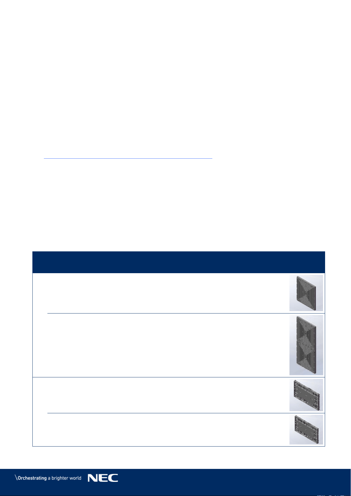
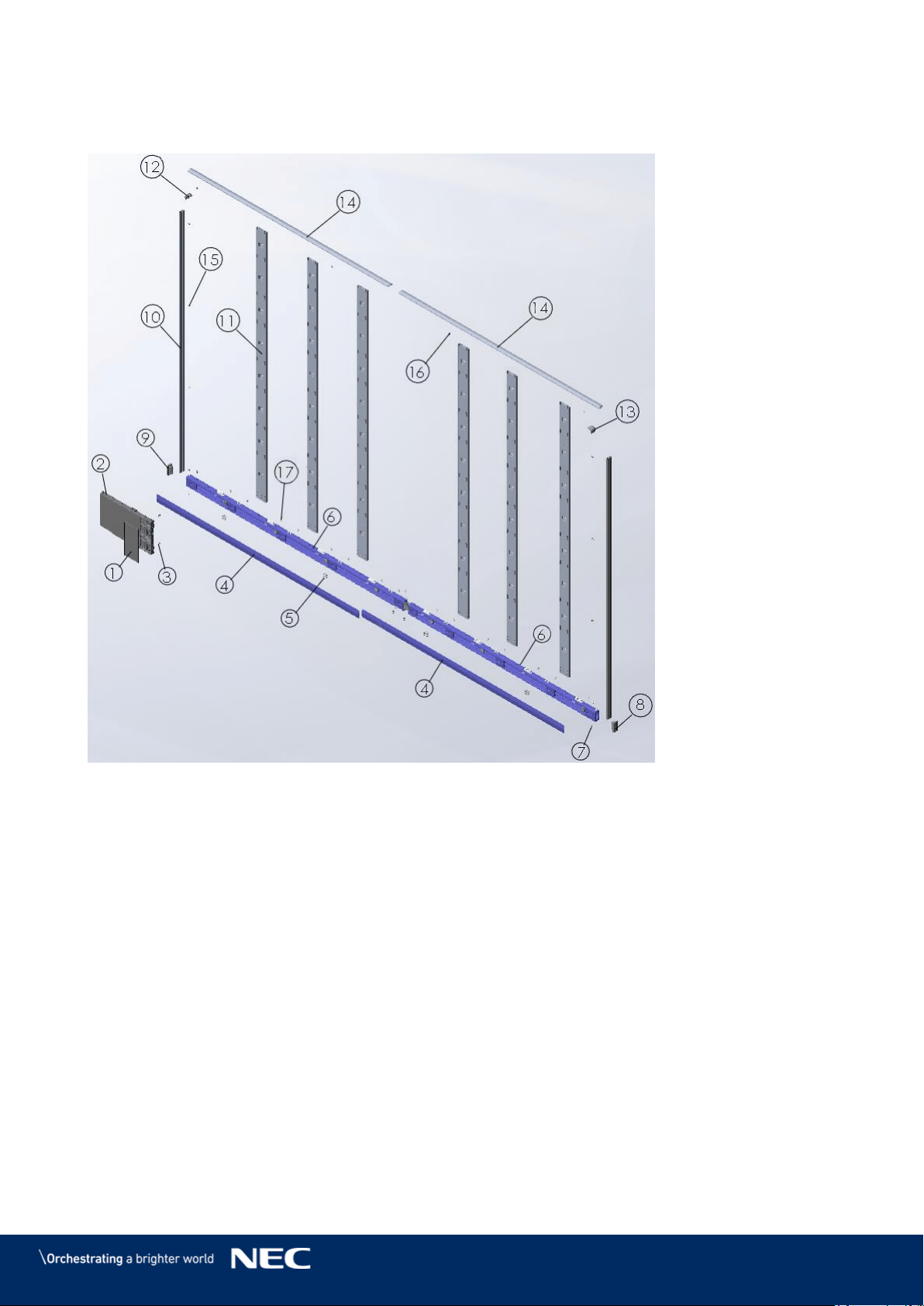
3.3
Framesets for Bundles
This chapter contains an overview for the setup of the wall frame for either 4×4, 5×5, 6×6 or 8×8
modules. Table 2 gives relevant information for each bundle size.
Table 2: FE Series Bundles
4 × 4 Modules
5 × 5 Modules
6 × 6 Modules
8 × 8 Modules
Bundle models
LED-FE012i2-110
LED-FE019i2-110
LED-FE015i2-137
LED-FE019i2-165
LED-FE012i2-220
LED-FE025i2-220
LED-FE038i2-220
Display size
(inch/cm)
110 / 279
137 / 348
165 / 419
220 / 559
Dimensions incl.
frame (W × H)
2472×1488 mm
3080×1830 mm
3688×2172 mm
4904×2856 mm
Weight
182 kg
279 kg
391 kg
659 kg
See section 3.2 List of Parts for complete list of parts, names and quantities. The positions given
in the following illustration refer to the List of Parts.
Frameset for LED-FE012i2-110 and LED-FE019i2-110 (4×4 Modules) 3.3.1
Figure 1: Frameset for LED-FE012i2-110 and LED-FE019i2-110 (4×4 Modules)
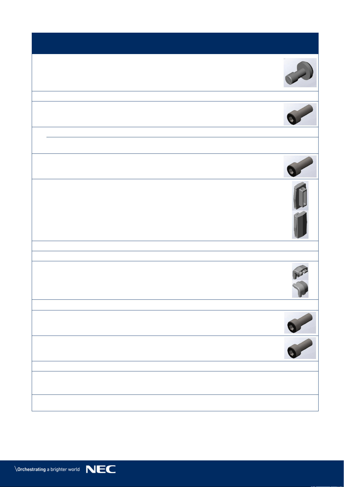
17
Frameset for LED-FE015i2-137 (5×5 Modules) 3.3.2
Figure 2: Frameset for LED-FE015i2-137 (5×5 Modules)
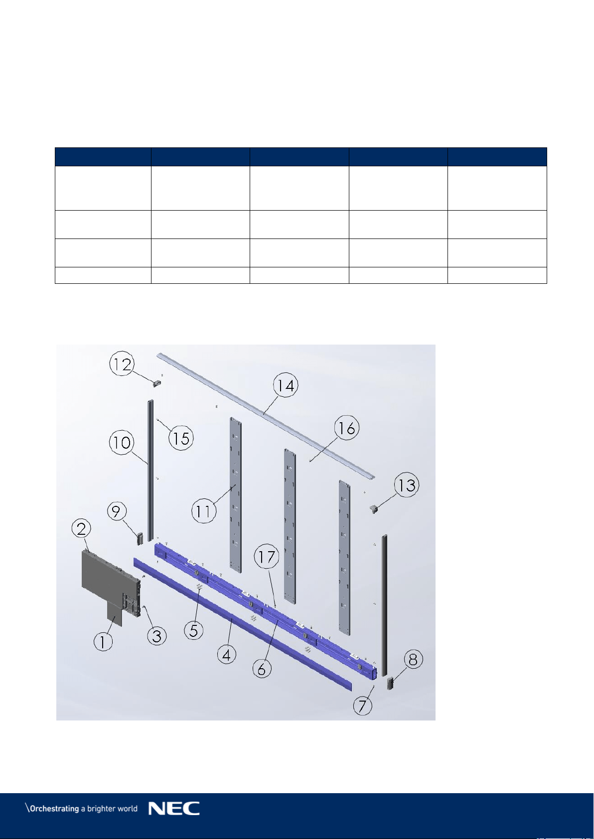
Frameset for LED-FE019i2-165 (6×6 Modules) 3.3.3
Figure 3: Frameset for LED-FE019i2-165 (6×6 Modules)
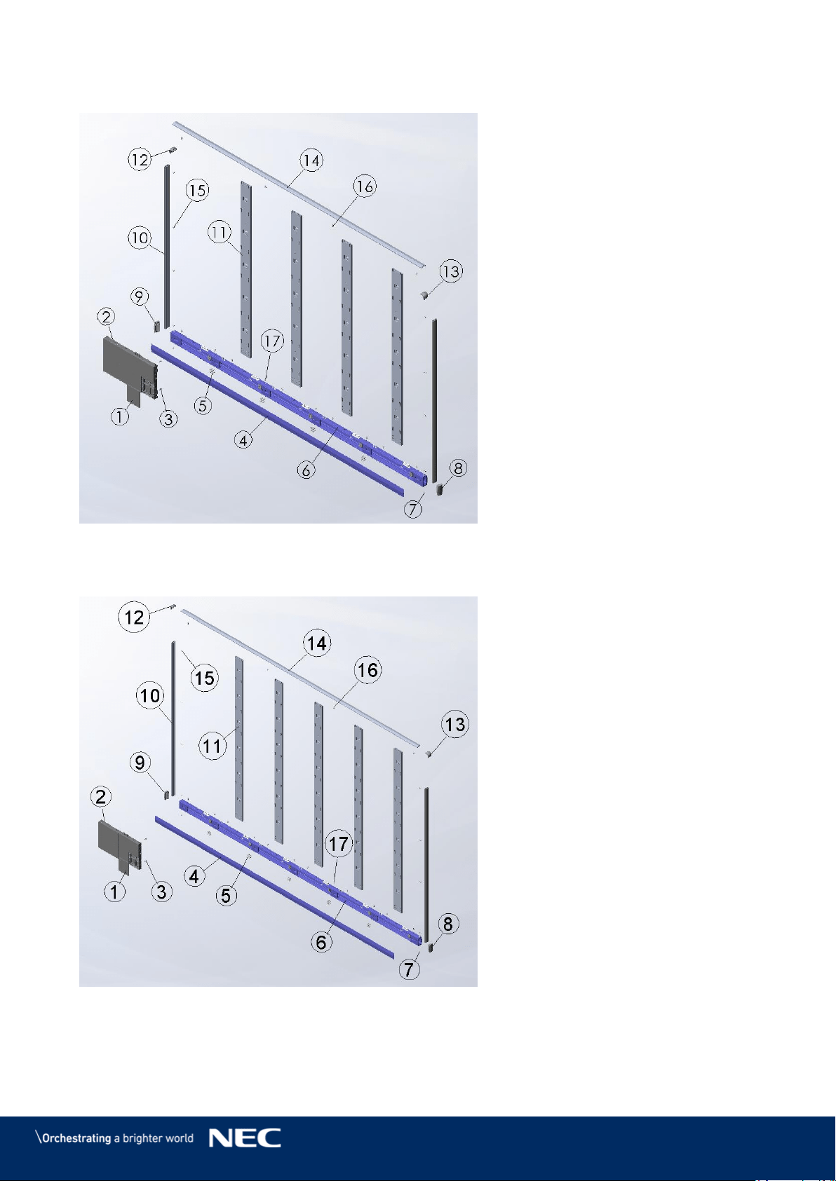
18
Frameset for LED-FE012i2-220 and LED-FE025i2-220, LED-FE038i2-220 (8×8 3.3.4
Modules)
Figure 4: Frameset for LED-FE012i2-220 and LED-FE025i2-220, LED-FE038i2-220 (8×8
Modules)
19
3.4
Specification
Table 3: Product Specification for Modules
Module model
LED-FE012i2
LED-FE015i2
LED-FE019i2
LED & Pixel Card
LED configuration
3in1 SMD
Pixel pitch
1.266 mm
1.583 mm
1.90 mm
Pixels (W × H)
120 × 135
96 × 108
80 × 90
Pixel card size
152 × 171 ×10 mm
Module
Pixel card configuration
4 × 2
Resolution (W x H)
480 × 270
384 × 216
320 × 180
Module area
0.21 m²
Module size (W × H × D)
608 × 342 × 49 mm
Net weight
8.8 kg
Power
AC 100 V to AC 240 V, 50 Hz / 60 Hz
Type of protection
Front IP20 / Rear IP20
Service availability
Front service
Displays
Power max. | average
600 W/m²,
125 W/module |
315 W/m²,
66 W/module
600 W/m², 125 W/module |
280 W/m², 57 W/module
Viewing
angle
HOR.(L/R)
80° / 80°
VER.(U/L)
80° / 80°
Brightness
700 cd/m²
Brightness tolerance
±10%
Contrast ratio
4000:1
Operating temperature
-20 °C to +40 °C
Operating humidity
10% to 80% relative humidity, non-condensing
Strage temperature
-20 °C to +45 °C
Strage humidity
10% to 85 % relative humidity, non-condensing
LED Lifetime
(50% brightness)
100,000 hours
Color processing
16 bit
Refresh rate
up to 3840 Hz
Frame rate
50/60 Hz
Brightness level
manually and automatically 256 levels (8 bit)
Color temperature
3000K to 9500K (default:6500K)

20
Module model
LED-FE025i2
LED-FE031i2
LED-FE038i2
LED & Pixel Card
LED configuration
3in1 SMD
Pixel pitch
2.533 mm
3.167 mm
3.800 mm
Pixels (W × H)
60 × 135
48 × 54
40 × 45
Pixel card size
152 × 342 ×10 mm
152 × 171 ×10 mm
Module
Pixel card configuration
4 × 1
4 × 2
Resolution (W x H)
240 × 135
192 × 108
160 × 90
Module area
0.21 m²
Module size (W × H × D)
608 × 342 × 49 mm
Net weight
8.8 kg
Power
AC 100 V to AC 240 V, 50 Hz / 60 Hz
Type of protection
Front IP20 / Rear IP20
Service availability
Front service
Displays
Power max. | average
580 W/m², 120 W/module | 230 W/m², 47 W/module
Viewing
angle
HOR.(L/R)
80° / 80°
VER.(U/L)
70° / 70°
Brightness
1000 cd/m²
Brightness tolerance
±10%
Contrast ratio
5000:1
Operating temperature
-20 °C to +40 °C
Operating humidity
10% to 80% relative humidity, non-condensing
Strage temperature
-20 °C to +45 °C
Strage humidity
10% to 85 % relative humidity, non-condensing
LED Lifetime
(50% brightness)
100,000 hours
Color processing
16 bit
Refresh rate
up to 3840 Hz
Frame rate
50/60 Hz
Brightness level
manually and automatically 256 levels (8 bit)
Color temperature
3000K to 9500K (default:6500K)
21
Module model
LED-FE009i2
LED & Pixel Card
LED configuration
4in1 SMD
Pixel pitch
0.95 mm
Pixels (W × H)
160 × 180
Pixel card size
152 × 171 ×10 mm
Module
Pixel card configuration
4 × 2
Resolution (W x H)
640 × 360
Module area
0.21 m²
Module size (W × H × D)
608 × 342 × 49 mm
Net weight
8.8 kg
Power
AC 100 V to AC 240 V,
50 Hz / 60 Hz
Type of protection
Front IP20 / Rear IP20
Service availability
Front service
Displays
Power max. | average
720 W/m²,
150 W/module |
380 W/m²,
80 W/module
Viewing
angle
HOR.(L/R)
70° / 70°
VER.(U/L)
70° / 70°
Brightness
600 cd/m²
Brightness tolerance
±10%
Contrast ratio
5000:1
Operating temperature
-20 °C to +40 °C
Operating humidity
10% to 80% relative
humidity,
non-condensing
Strage temperature
-20 °C to +45 °C
Strage humidity
10% to 85 % relative
humidity,
non-condensing
LED Lifetime
(50% brightness)
100,000 hours
Color processing
16 bit
Refresh rate
up to 3840 Hz
Frame rate
50/60 Hz
Brightness level
manually and
automatically 256 levels
(8 bit)
Color temperature
3000K to 9500K
(default:6500K)
22
Module model
LED-FE012i2-E
LED-FE015i2-E
LED-FE019i2-E
LED & Pixel Card
LED configuration
3in1 SMD
Pixel pitch
1.266 mm
1.583 mm
1.90 mm
Pixels (W × H)
120 × 135
96 × 108
80 × 90
Pixel card size
152 × 171 ×10 mm
Module
Pixel card configuration
4 × 2
Resolution (W x H)
480 × 270
384 × 216
320 × 180
Module area
0.21 m²
Module size (W × H × D)
608 × 342 × 49 mm
Net weight
8.8 kg
Power
AC 100 V to AC 240 V, 50 Hz / 60 Hz
Type of protection
Front IP20 / Rear IP20
Service availability
Front service
Displays
Power max. | average
600 W/m²,
125 W/module |
315 W/m²,
66 W/module
600 W/m², 125 W/module |
280 W/m², 57 W/module
Viewing
angle
HOR.(L/R)
80° / 80°
VER.(U/L)
80° / 80°
Brightness
600 cd/m²
Brightness tolerance
±10%
Contrast ratio
4000:1
Operating temperature
-20 °C to +40 °C
Operating humidity
10% to 80% relative humidity, non-condensing
Strage temperature
-20 °C to +45 °C
Strage humidity
10% to 85 % relative humidity, non-condensing
LED Lifetime
(50% brightness)
100,000 hours
Color processing
16 bit
Refresh rate
up to 3840 Hz
Frame rate
50/60 Hz
Brightness level
manually and automatically 256 levels (8 bit)
Color temperature
3000K to 9500K (default:6500K)
23
3.5
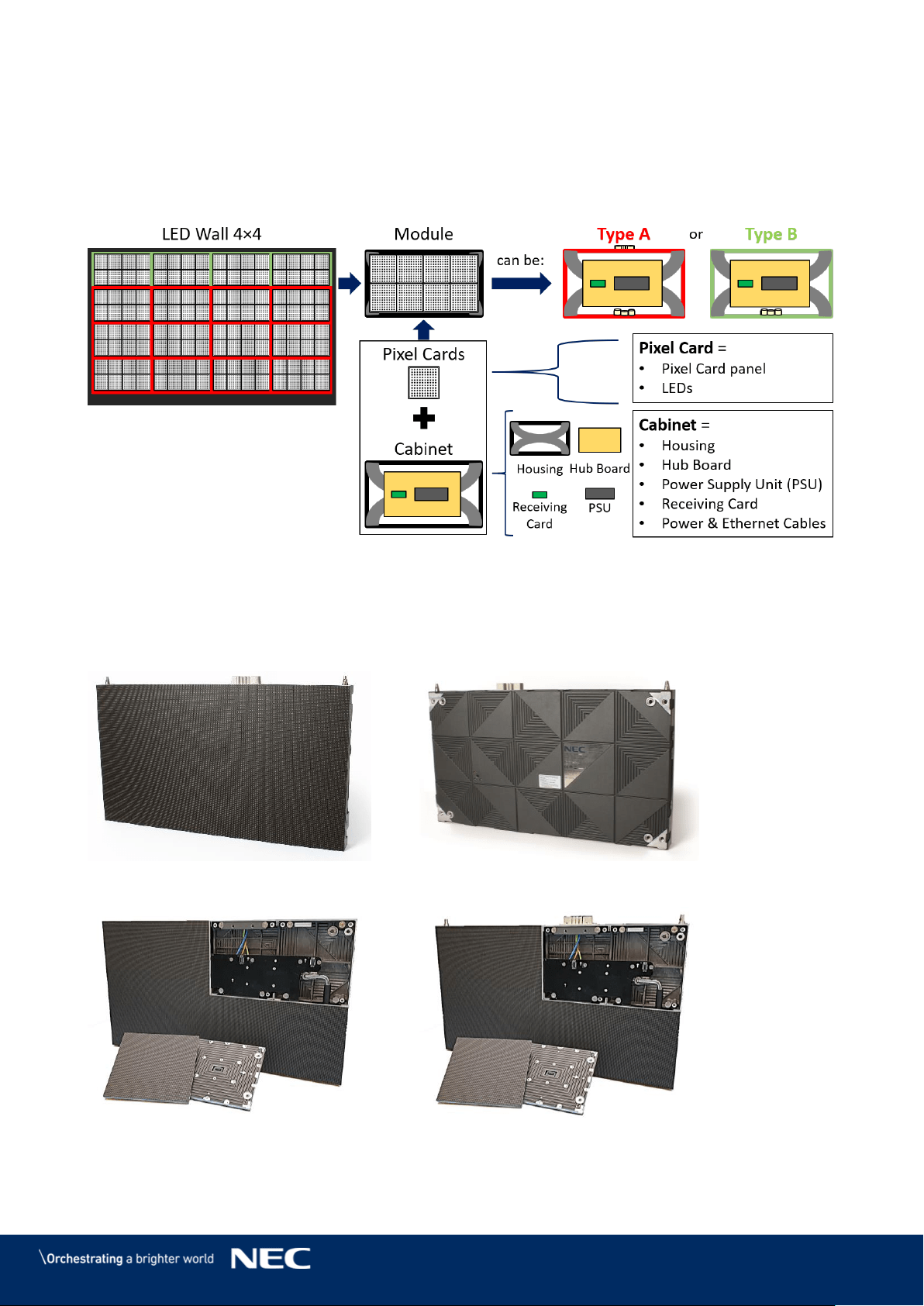
LED Wall Components
An LED Wall has the following components
Modules = Cabinet + Pixel cards
Frame structure (3.3 Framesets for Bundles)
Power bar (3.5.7 Power Bar)
Figure 5: LED Wall Components
Module 3.5.1
The module consists of eight Pixel cards and a cabinet. For information on Type A and B
modules/cabinets, see 3.5.2 Cabinet.
Figure 6: Type A Module – Front View
Figure 7: Module – Back Side
Figure 8: Type B Module – Open
Figure 9: Type A Module – Open
24
Cabinet 3.5.2
Each cabinet has a combination of structural and technological functionalities that constitute a
robust, stable, protective, and safe LED Wall. Additionally, the LED Wall is easy to build, maintain
and service through the cabinet system.
Figure 10: Type A Cabinet – Front
Type A Cabinets have two connectors for power (Power supply socket), one on the top and one
at bottom of the case (see Figure 11).
Type B Cabinets have only one connector for power (Power supply socket) on the bottom of the
case. This allows for the Overframe (top) to be placed directly on top of the housing for perfect
closure of the frame.
Backside hole Cabinets exist.
Please see the 15.2 Backside hole cabinet.
Figure 11: Type A and Type B Cabinet
A
B
25
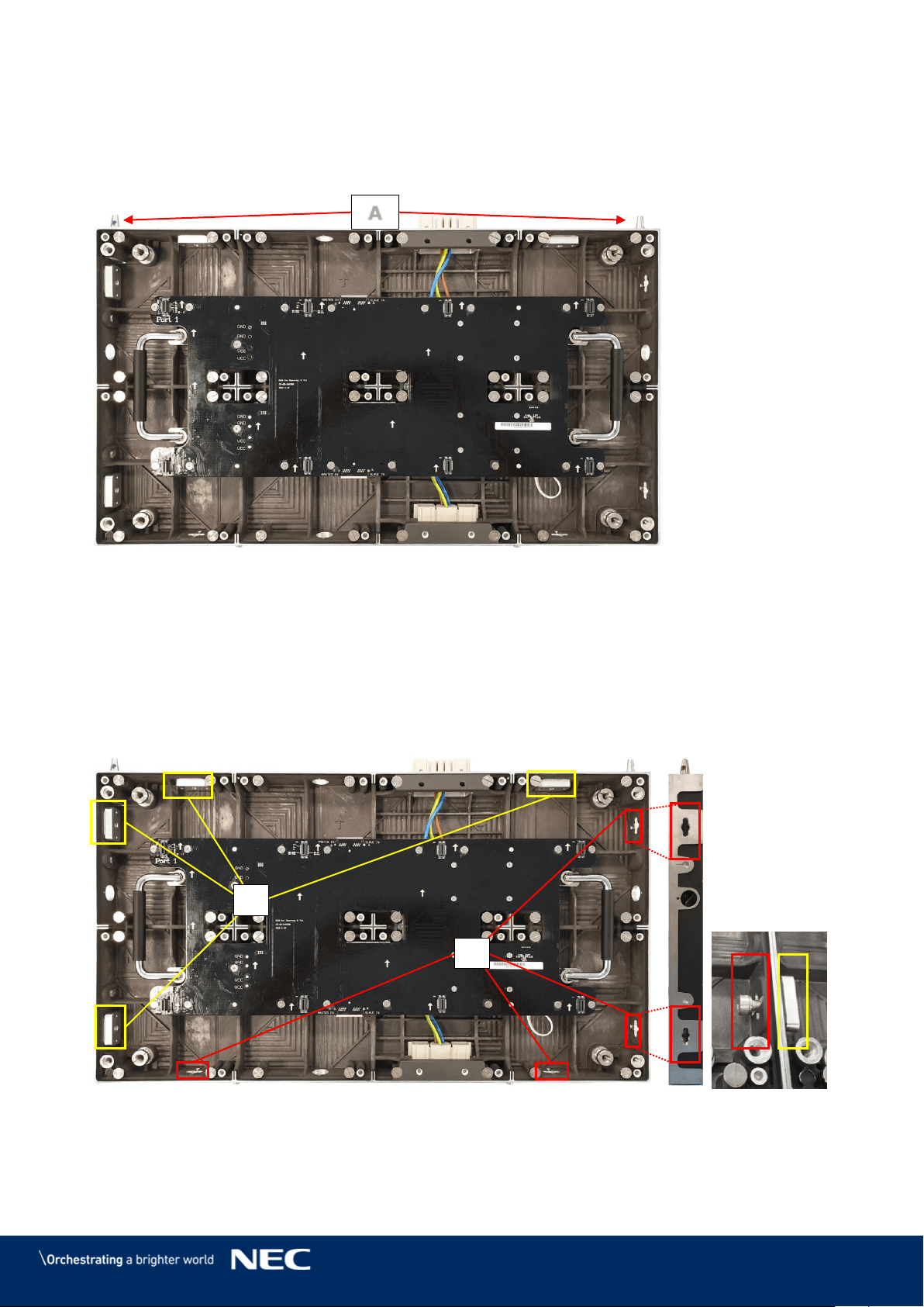
3.5.2.1
Corner Alignment Pins
At the top of each FE Series cabinet are two special corner locating pins (Figure 12, A) – with a
diagonal inside the corner pin. This design allows the cabinets to be securely stacked upon each
other for up to 15 layers – reaching at total height of 5 meters.
Figure 12: Corner Alignment Pins
3.5.2.2
Screw Connection for Cabinets
The Screw connections between the cabinets guarantee quick installation and easy maintenance.
Each cabinet has two sets of Screw connections:
two sets of Allen screw anchors – right and bottom (B)
two sets of Counter plates – left and top (C)
This design allows modules to interconnect tightly in order to create a seamless LED Wall display.
Figure 13: Screw Connections for Cabinets: Screws and Counter plates
Section 6.3.2 explains how to interlock two cabinets.
A
C
B
26
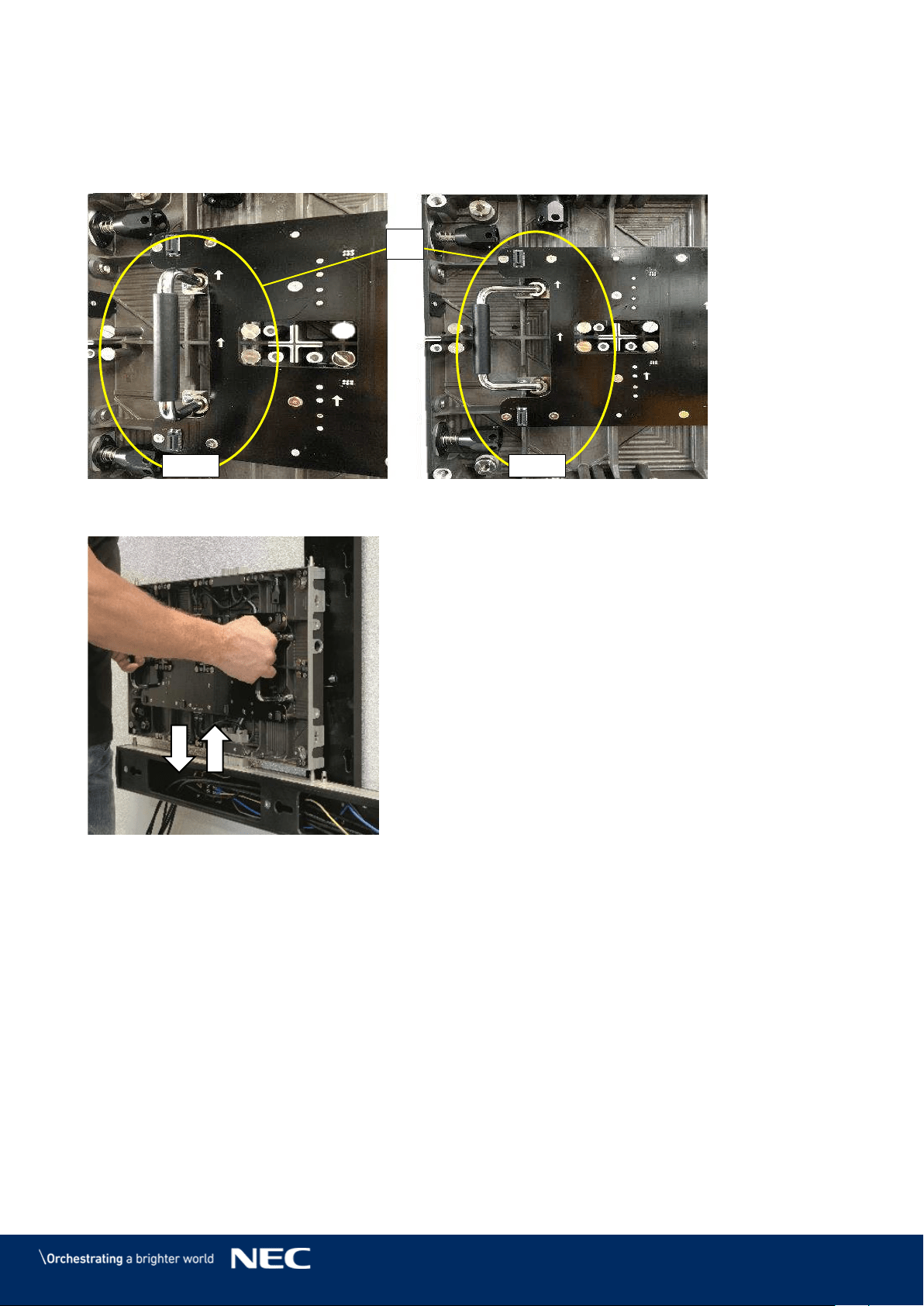
3.5.2.3
Grip Handles
The grip handles (Figure 14) are bolted into the cabinet, middle-center, left and right from the hub
board. These provide for easy handling during installation and maintenance in the open-position,
and conveniently collapse into the cabinet when not in use (Figure 14, Figure 15).
Figure 14: Grip Handle in Open and Closed Positions
Figure 15: Grip Handles in Use
Open
Closed
D
27
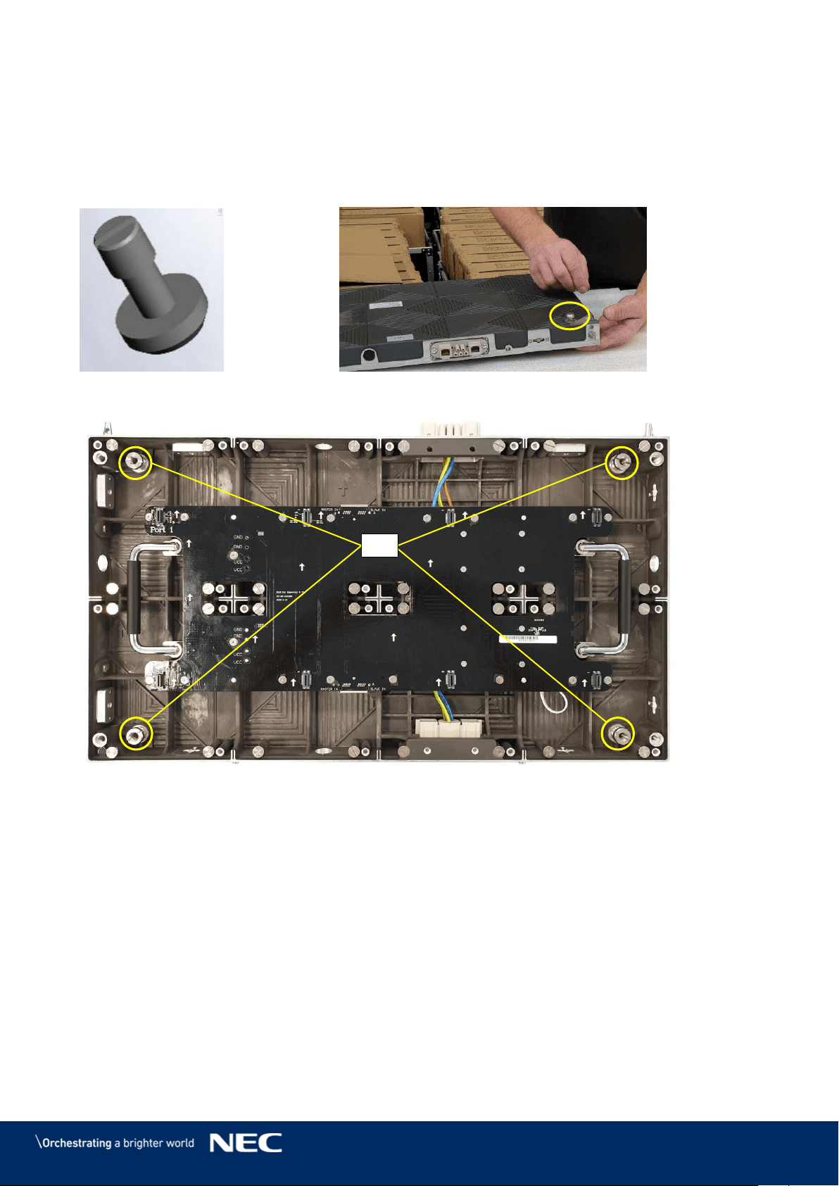
3.5.2.4
Cabinet Hanger Pins
Cabinet hanger pins (Figure 16) are attached on the back of the cabinet (Figure 17) and secured
on the inside of the cabinet (Figure 18, H).
If used as fixed installation, optional matched connectors can be adopted to connect the Corner
alignment pin and support frame.
Figure 16: Cabinet Hanger Pin
Figure 17: Installing Cabinet Hanger Pins
Figure 18: Cabinet Hanger Pin Connectors
H
28
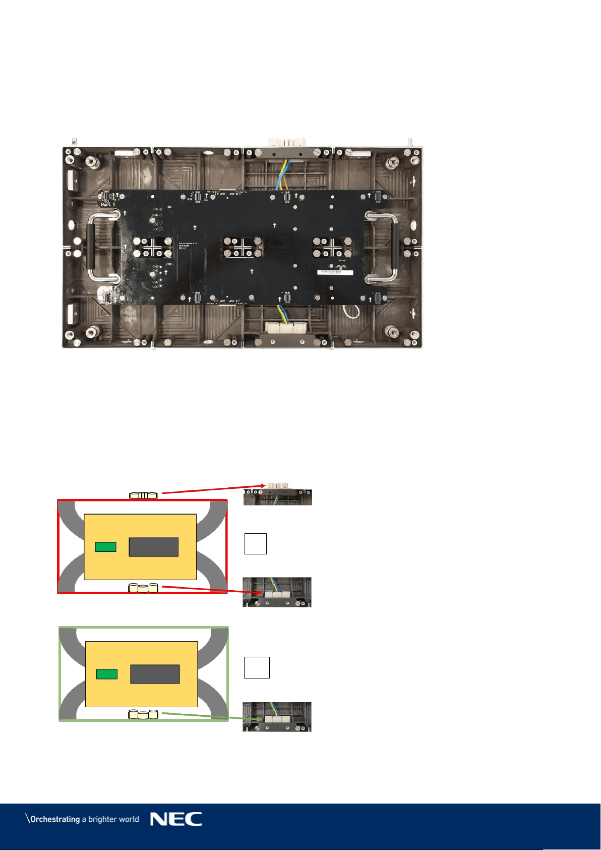
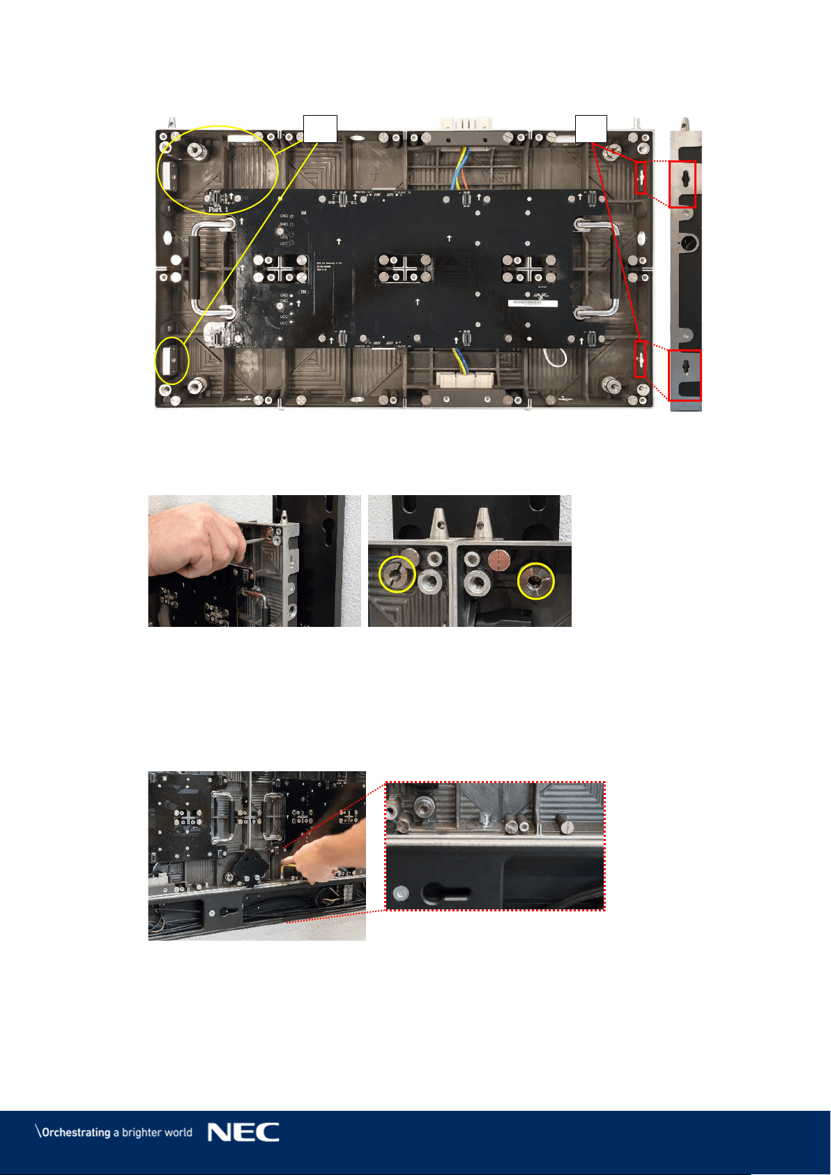
3.5.2.5
Power Supply Socket
The Power supply sockets (Figure 19, A) distribute the power for each column of modules in the
LED Wall. The sockets are male and female adapters at the top and bottom surfaces of the cabinet.
The sockets interconnect two cabinets of a column (Figure 20). The socket is connected to the
Power distribution unit (PDU) (wiring, C).
The sockets wire to the PDU (Figure 21, D) and ground (E) on the cabinet. The PDU, in turn,
connects to the Power supply unit (F) via the hub board's power supply connector (see also Figure
27, D, p. 31).
Figure 19: Power Supply Sockets – Top and Bottom
Figure 20: Connected Sockets
Figure 21: Sockets Wired to PDU behind Hub Board
A
B
C
F
E
D
29
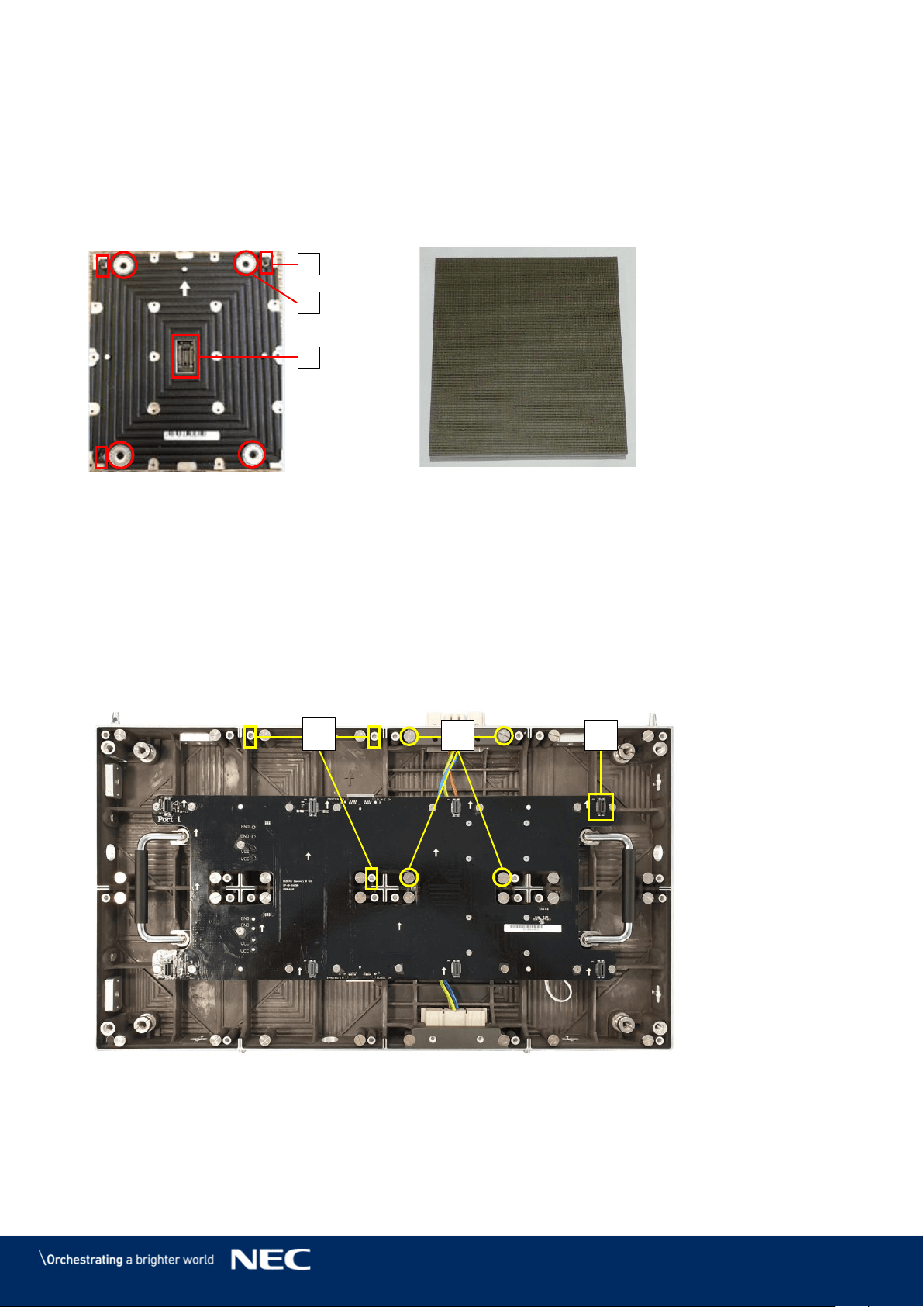
Pixel Card 3.5.3
The Pixel cards display segments of the picture on the front. On the back, the Pixel card has three
components, which keep the Pixel card in position on the cabinet:
3 corner click-pins (A)
4 magnets (B)
1 Pixel card connector (C)
Figure 22: Pixel Card – Back
Figure 23: Pixel Card – Front
Connections on the Hub board and the Cabinet
For installation and operation, the Pixel card needs no cable connections to the Hub board or
Cabinet. Three types of interfaces help to secure Pixel cards within the cabinet.
Click-pin interfaces (D): counter-part to the corner click-pins on Pixel card; ensure the right
position of the Pixel card on the cabinet.
Level screws (E): counter-part to the magnets on the Pixel card; enable to adjust possible
protrusion of the Pixel card to smoothen the surface of the LED Wall.
Pixel card network interface (F): counter-part to Pixel card connector; for data
transmission and power supply to the Pixel card.
Figure 24: Pixel Card Interfaces on Hub Board and in Cabinet
A
B
C
E
D
F
30
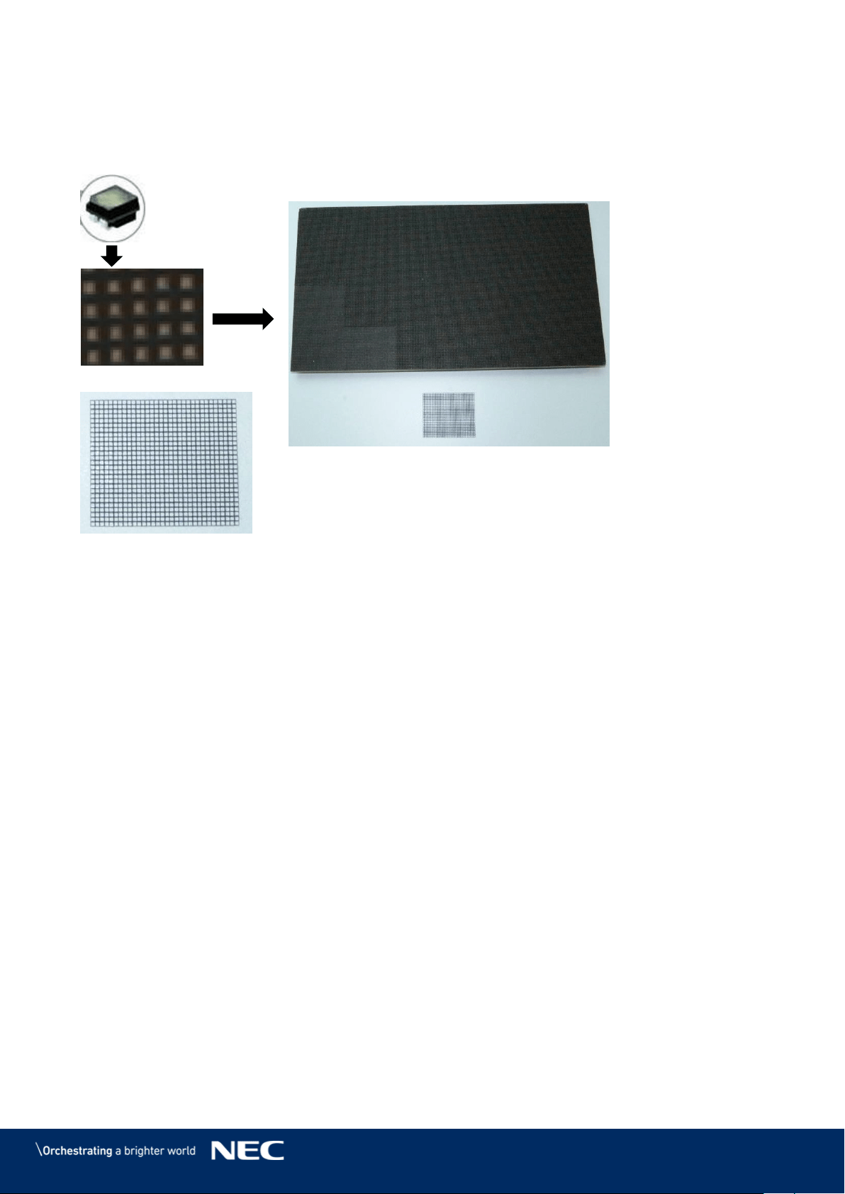
Black Masks
The Black masks cover and protect the electronic surface between the LEDs of the Pixel card PCB.
In combination with our high-end LED-chips (A), the mask (B) is necessary to get the best
black-values, which result in a high contrast ratio of the screen.
Figure 25: LED Chip and Usage of the Black Masks
A
B
31
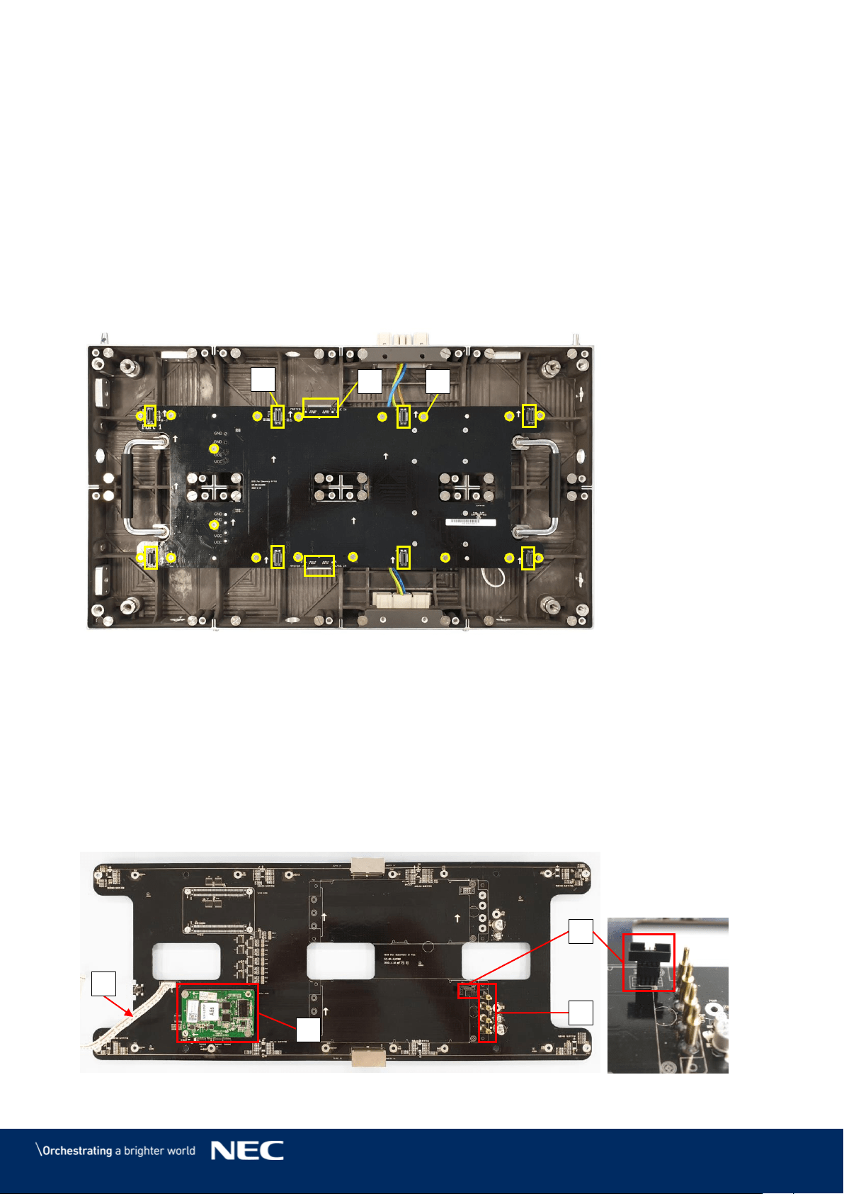
Hub Board 3.5.4
The Hub board distributes the signals, data and power to other hardware components in the
cabinet, such as Receiving card, power supply and Pixel cards. Each Hub board has a Power
supply unit (PSU) and a Receiving card.
Hub Board Interfaces
The Hub board has several interfaces to distribute power and data. The Hub Board front (Figure
26) has the following interfaces:
8 Pixel card network interfaces (A): For data transmission and power supply to Pixel cards.
2× 2Ethernet ports (B): For data transmission from Hub board to Hub board. (Only the left
Ethernet port transmits data. The right Ethernet port has no function.)
16 screw connections to cabinet (C): To secure the Hub board in the cabinet.
Figure 26: Hub Board – Front
The backside of the Hub board has several interfaces for data and power distribution (Figure
27):
4 pin connectors to Power supply unit (D): Distribute the power from PSU to the Hub board,
e.g. for the Pixel cards or Receiving card.
1 Power-good-connector (E): Sends status of power supply to monitoring software.
Be careful when re-assembling the module, the connectors bend easily.
1 Receiving card (F): Receives data and signal input via the Ethernet cable from the external
controller. They process the signals and forward them to the Pixel cards.
1 Signal light cable (G): Forwards the status input of the module to the Signal lights on the
back of the module.
Figure 27: Hub Board – Back
A
B
C
F
G
D
E
32
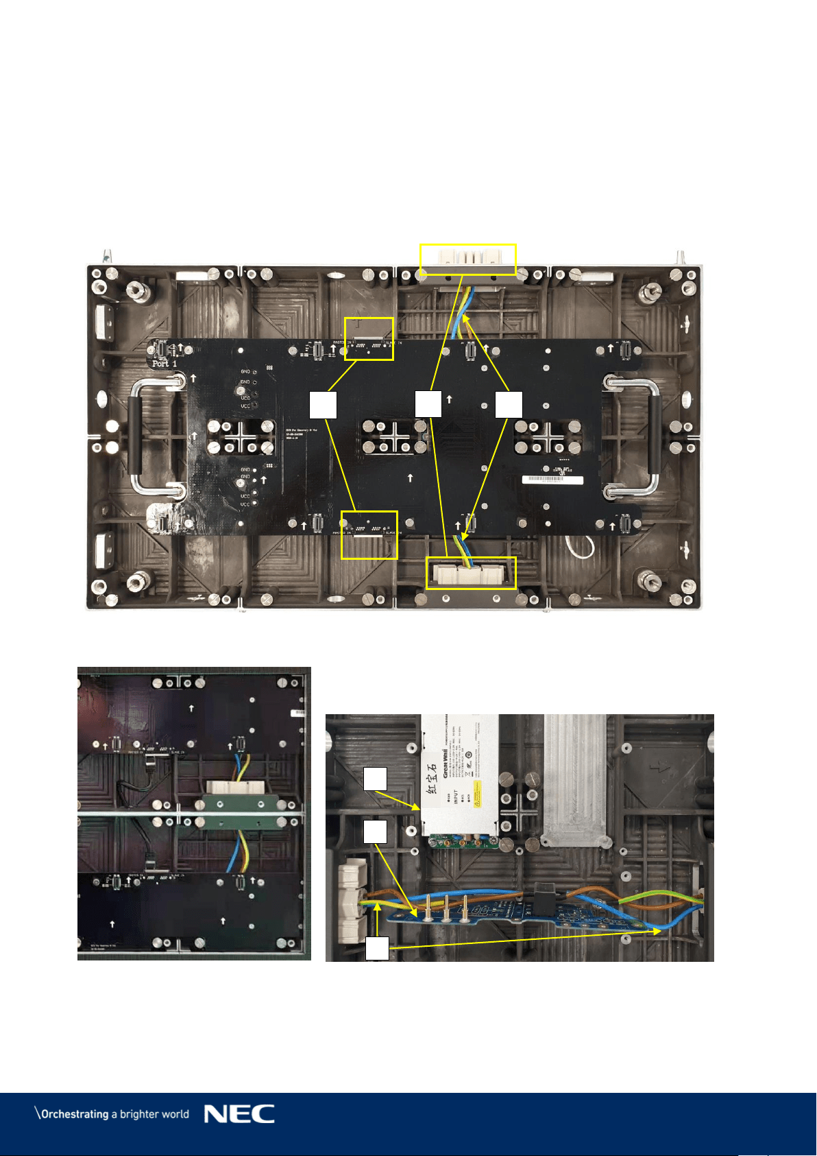
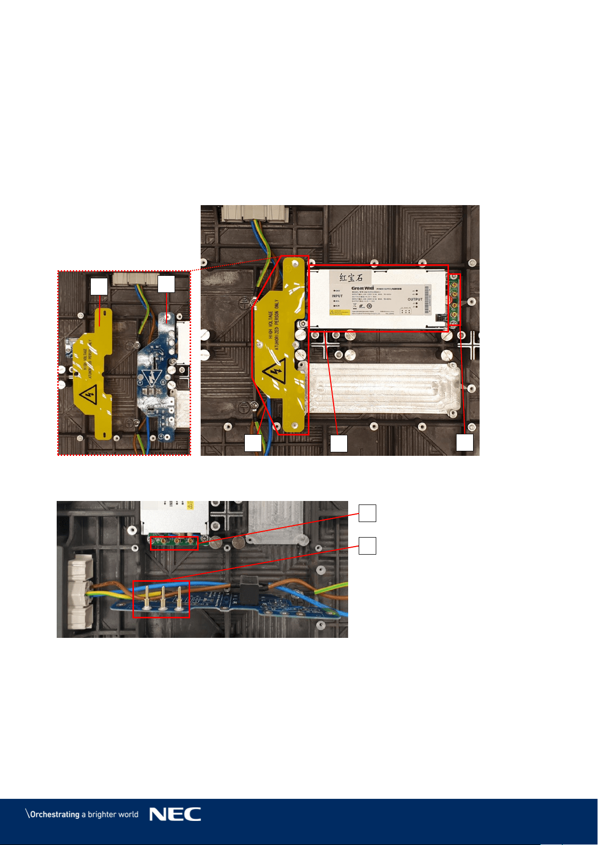
Power Supply 3.5.5
In each module, one Power supply unit (PSU) connects through a Power distribution unit (PDU) to
the power input.
The following components contribute to the power supply of a module:
1 Power supply unit (PSU) (A)
1 Power distribution unit (PDU) (B1) with PDU shielding (B2): The PDU shielding protects the
high voltage components from being touched by accident. Do not remove while power is
connected!
1 Power supply interface to Hub board (C): Counter-part to the Hub board's four pin connector
to supply the Hub board with power.
Figure 28: Behind Hub Board –Power Supply with Wired PDU with PDU Shielding
The PDU connects to the PSU via three pin connectors (D) for each PSU interface (E).
Figure 29: Pin Connection from PDU to PSU
B2
B1
B
A
C
E
D
33
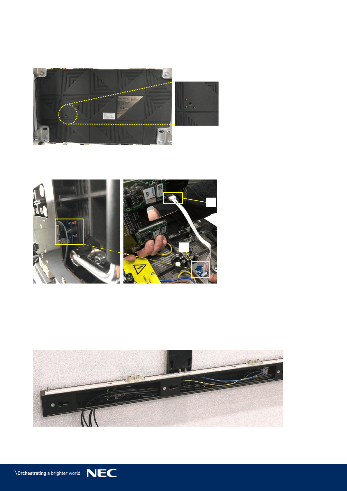
Signal Lights 3.5.6
The Signal lights are on the back of the module (Figure 30). They indicate the status of the
module. The three lights are red, green and blue.
Figure 30: Signal Lights on the Back of the Module
The Signal lights are fixed on a PCB (A) to the inner backside of the cabinet and connected to the
Hub board with the Signal light cable (B).
Figure 31: Signal Light Interface Connected to Hub Board
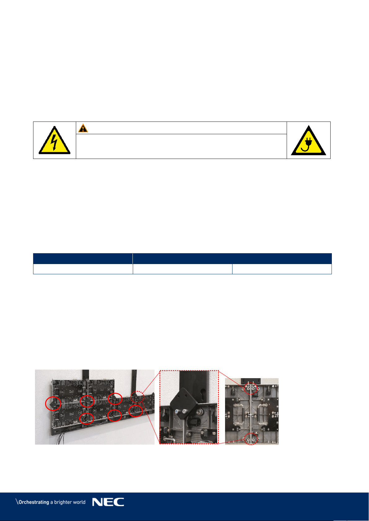
Power Bar 3.5.7
The Power bar is the LED Wall component for the distribution of data and power. It is located at the
bottom of the LED Wall and connects to each row of modules via the Network and power supply
socket. The Power bar also serves as cable conduit: The cables for power supply and data
transmission run inside the Power bar from Hub boards and the terminals to the exit points on the
back of the Power bar.
Figure 32: Power Bar with Cable Exit Point
A
B
34
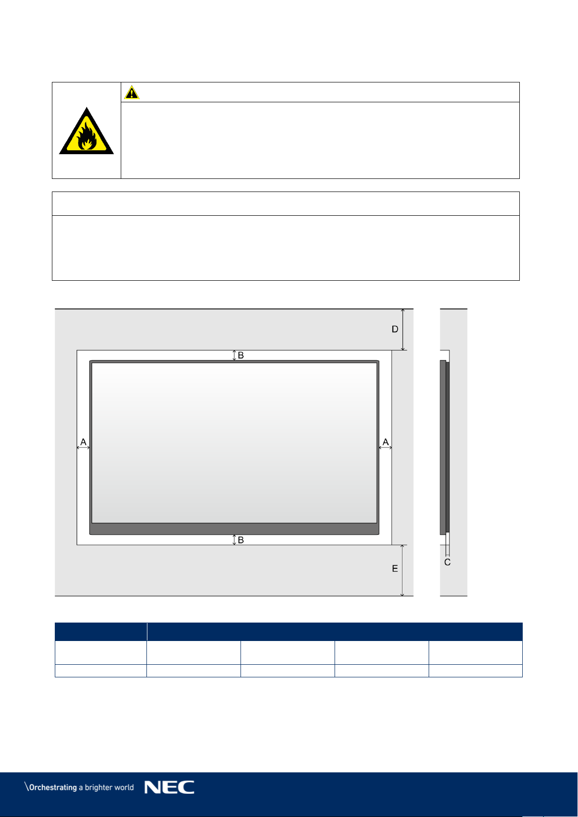
3.6
Ventilation Requirements
Caution!
Risk of fire, injuries and product damage due to overheating of the system.
Ensure proper ventilation and air flow around the system.
Never block the ventilation spaces around the LED Wall. Keep them free at all
times.
Never install the system air-tight into an alcove. Always leave the required
minimum ventilation space.
Notice
The values under D and E in the table below (see Figure 33) are reference values. Make sure the
room is well ventilated so that hot air generated by the product does not accumulate. Also, make
sure the room temperature is within the range of the environment temperature specification.
If you have questions, please contact NEC DISPLAY SOLUTIONS, see 1.2 Service & Support in
Europe.
Minimum Ventilation Spaces for Buried Installation (in Wall Alcove)
Figure 33: Ventilation Space for Buried Installation
A
B
C
D
E
min distance to
sides
min. distance to
top and bottom
Distance between
wall and system
min. distance to
ceiling
min. distance to
floor
60 mm
60 mm
30 mm
500 mm
700 mm
35
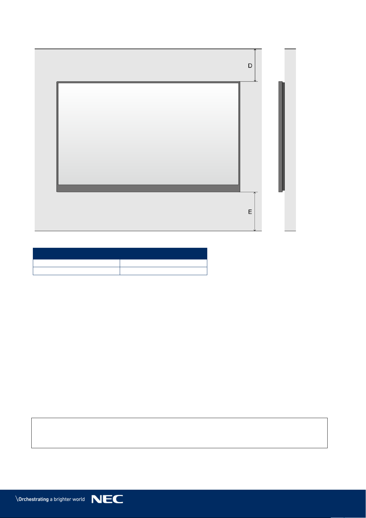
Minimum Ventilation Spaces for On-Wall Installation
Figure 34: Ventilation Space for On-Wall Installation
D
E
min. distance to ceiling
min. distance to floor
500 mm
700 mm
Heat Dissipation
3.6.1
The FE Series is provided with a highly efficient LED chip to reach low power consumption, less
heat production and a long working life.
The modules are designed fan-free which ensures a super quiet operation. The whole housing of
the module is designed as heat sink.
Cooling 3.6.2
The required ventilation depends on each particular project. Depending on the structural design
and environmental temperature it may be necessary to add an external cooling.
To integrate the ideal, energy-efficient air conditioner for the LED display, you have to determine
the capacity or size you need. This is important for two reasons: An undersized unit will not cool
adequately the LED display in extremely hot weather. An oversized air conditioner can also
adversely affect your comfort. The unit may switch on and off too often, without running long
enough to dehumidify the LED display properly or cool the space uniformly. And it will consume
more energy than necessary.
Info
The ideal environment temperature for the LED display is 10 – 25 °C.
36
4
ACCESSORIES
4.1
Power Supply and Connecting Cables
Power Supply for Power Bar 4.1.1
Internal: The internal electricity wiring is connected to a terminal in the Power bar.
External: A power cord to supply power is not included. Provide a sufficient connection to mains.
For more information, see 15.1 Cable Plans.
Warning!
Only trained personnel, such as electricians or NEC personnel, may
connect the internal power supply to mains power supply.
Signal Cable
4.1.2
Internal: The modules are connected via the delivered CAT cables between the Hub boards,
which also forwards the signal to the next modules.
External: FE Series to NovaStar Controller: The FE Series comes with signal cables (FTP
Cat5e) to connect data output of the NovaStar Controller to the Ethernet port on the first Hub
board of each column. For more information, see 15.1 Cable Plans.
External: NovaStar Controller to PC: Signal cables to connect the NovaStar Controller and a
PC are included. Refer to Table 4 to choose the correct signal cable for that task.
Table 4: Compatible Signal Cable (Video Distributor)
DVI single link
HDMI
3G-SDI
Cable included in delivery
Cable included in delivery
Cable not included in delivery
4.2
Adjustment plate
When installing cabinets, the horizontal and vertical alignment for the whole LED wall is important
so that the image surface is even – without image distortions or light aberrations.
During installation, the Adjustment plates help to align the cabinets across a given row and with
the neighboring rows. The Adjustment plates line up the connecting edges and surfaces of the
cabinets. They are used at each junction point.
After the installation of the cabinets is finished, remove the Adjustment plates. Otherwise, the
Pixel cards do not fit on the cabinet.
Figure 35: Adjustment plate
37
5
PREPARE FOR USE
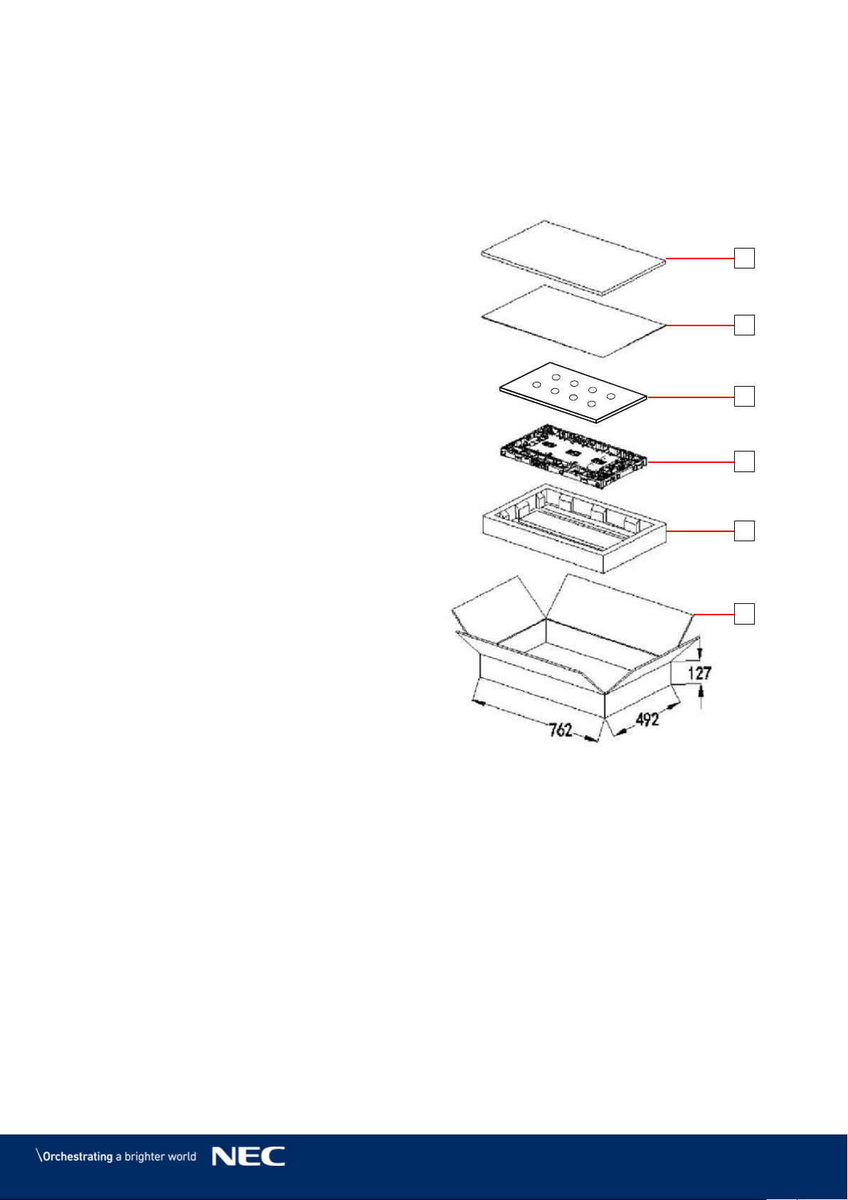
5.1
Cabinet Packaging
One cabinet box contains the following:
Foam cover (1)
PE bag (2)
Cabinet (3)
Foam container (4)
Cardboard box (5)
Figure 36: Package Order of Module Box
1
2
1
3
4
5
38
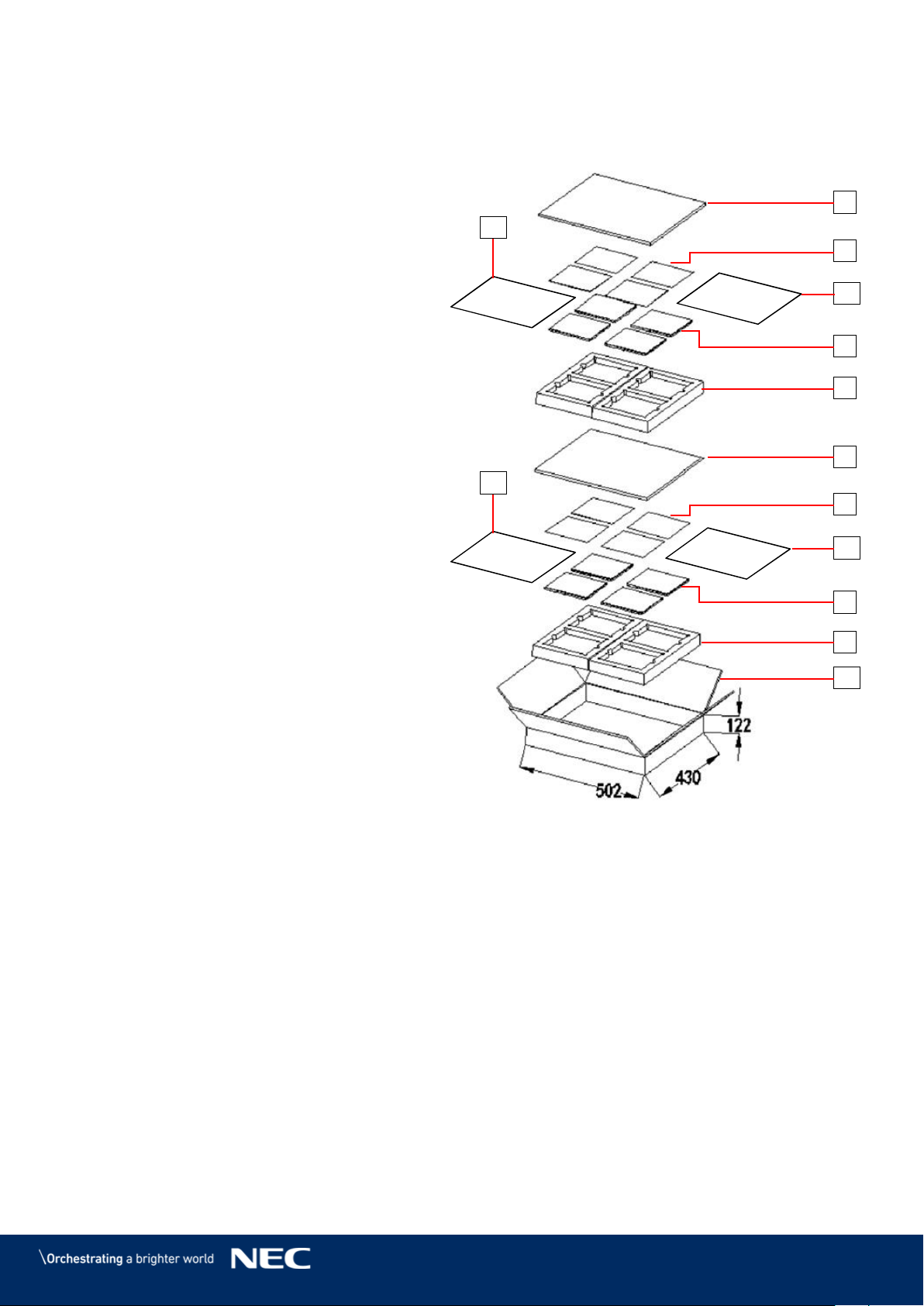
5.2
Pixel Cards Packaging
One Pixel card box contains the following:
Foam cover (6)
Antistatic bag (7)
Pixel card (8)
Foam container (9)
Cardboard box (10)
PE bag (11)
Figure 37: Package Order of Pixel Card Box
6
11
11
9
6
7
11
8
9
11
10
7
8
39
5.3
Installation Setup – Wall Mounting
For the limited space for installation, you may either cut a same size space as the LED display on
the wall, then install the LED display in this space or fix the support structure directly onto the wall.
It requires solid walls. Observe the ventilation requirements, see 3.6 Ventilation Requirements.
All additional fixation components and tools must be determined by a detailed static calculation to
ensure a safe and high-performance LED system. Front maintenance will be very convenient.
See section 6.1 for detailed instructions on wall mounting.
Caution!
Risk of personal injury and product damage by unsuitable wall mounting
equipment.
Before starting the installation:
Ensure that the installation site is suitable for the cable routing plan. If
necessary, mark important points of the plan on the wall used for the
installation.
Regarding the installation site: Analyze the wall used for the installation and
the weight of the complete LED Wall (see Table 5). Choose installation
equipment, e.g. tools, screws and dowels, that are suitable for the wall
conditions and the weight of the LED Wall.
Stability hazard:
The device may fall, causing serious personal injury or death. To prevent injury,
this device must be securely attached to the floor/wall in accordance with the
installation instructions.
Table 5: Dimensions and Weight for LED Wall 4×4, 5×5, 6×6, 8×8
4 × 4 LED Wall
5 × 5 LED Wall
6 × 6 LED Wall
8 × 8 LED Wall
Dimensions incl.
frame (W × H)
2472×1488 mm
3080×1830 mm
3688×2172 mm
4904×2856 mm
Weight
182 kg
279 kg
391 kg
659 kg
40
6
ASSEMBLE COMPONENTS
Notice
Read the safety guidelines, which are included in the delivery. Follow them strictly to ensure
safety and a high-performance LED system!
6.1
Install Mounting bars for Wall Mounting
This section is a guide to the mounting of the Mounting bar and describes the following in more
detail:
Prepare the support structure according to the installation site requirements.
Prepare the wall for installation.
Then fix the structure on its designated place according to the static requirements.
Table 6: Mounting bar – Installation requirements
No. of People
2
Tools
Ladder/ elevated working platform
Tools for mounting (e.g. hammer,
screwdriver, Allen key, jaw spanner)
Drilling equipment (e.g. drilling machine
and fitting attachment/head)
depending on mounting surface,
wall material/condition
Mounting material (screws, dowels etc.)
depending on
overall weight of chosen screen
system
mounting surface, wall
material/condition
Measurement tools (e.g. rule, spirit level)
Alignment bar
Included in delivery, flat black bar
Equipment
See for 3.3 Framesets for Bundles specifications related to:
Frameset for LED-FE012i2-110 and LED-FE019i2-110 (4×4 Modules)
Frameset for LED-FE015i2-137 (5×5 Modules)
Frameset for LED-FE019i2-165 (6×6 Modules)
Frameset for LED-FE012i2-220 and LED-FE025i2-220, LED-FE038i2-220
(8×8 Modules)
Prepare the Wall Surface 6.1.1
Remove debris and clean the wall surface.
Measure the dimensions for the bundle according to wall frame specifications for the target
frameset: 4×4, 5×5, 6×6, 8×8.
Notice
Ensure proper ventilation of the LED Wall. For more information, see 3.6 Ventilation
Requirements.
Consider the cable plans, see 15.1 Cable Plans and ensure the cables can be placed properly.
41
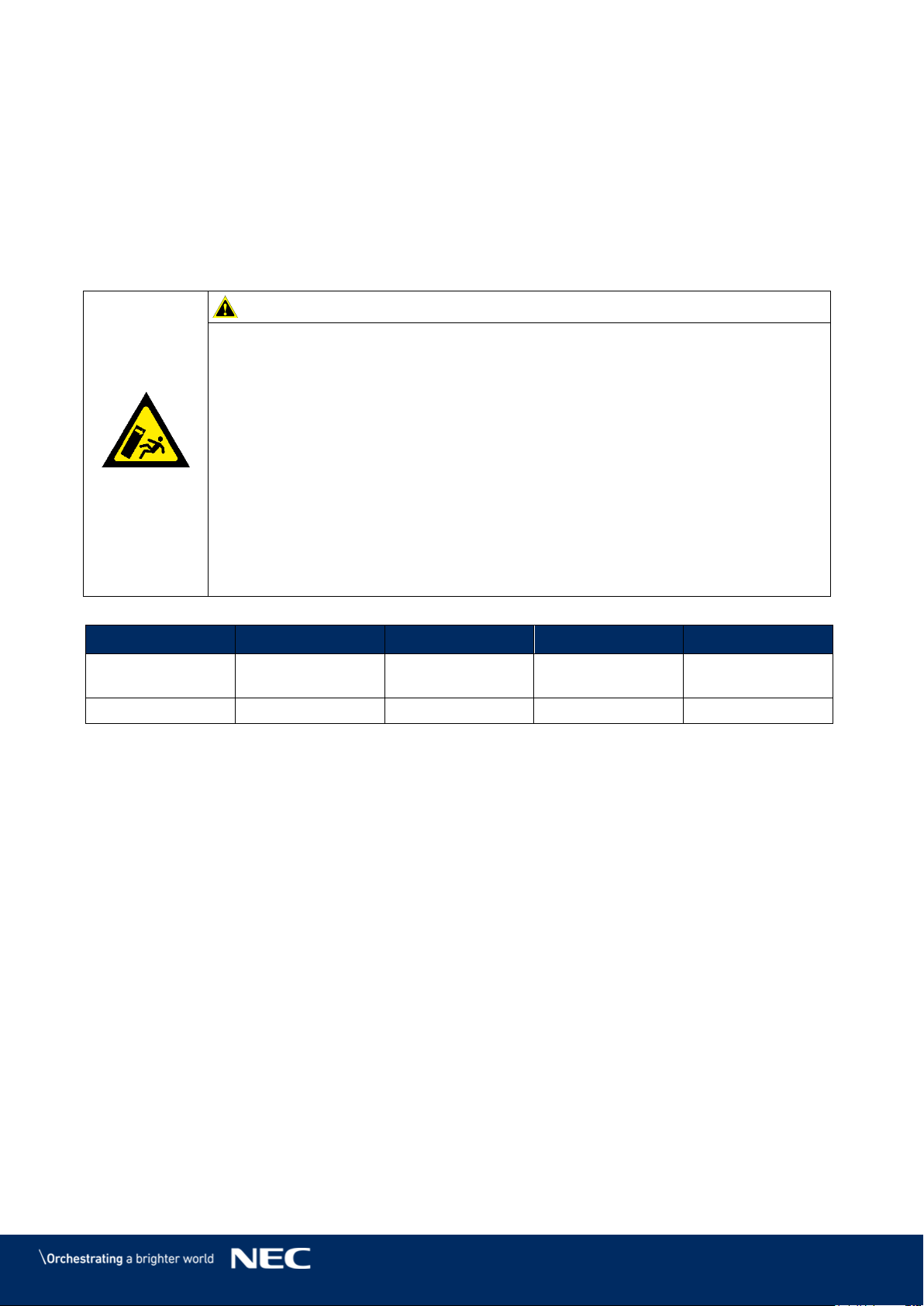
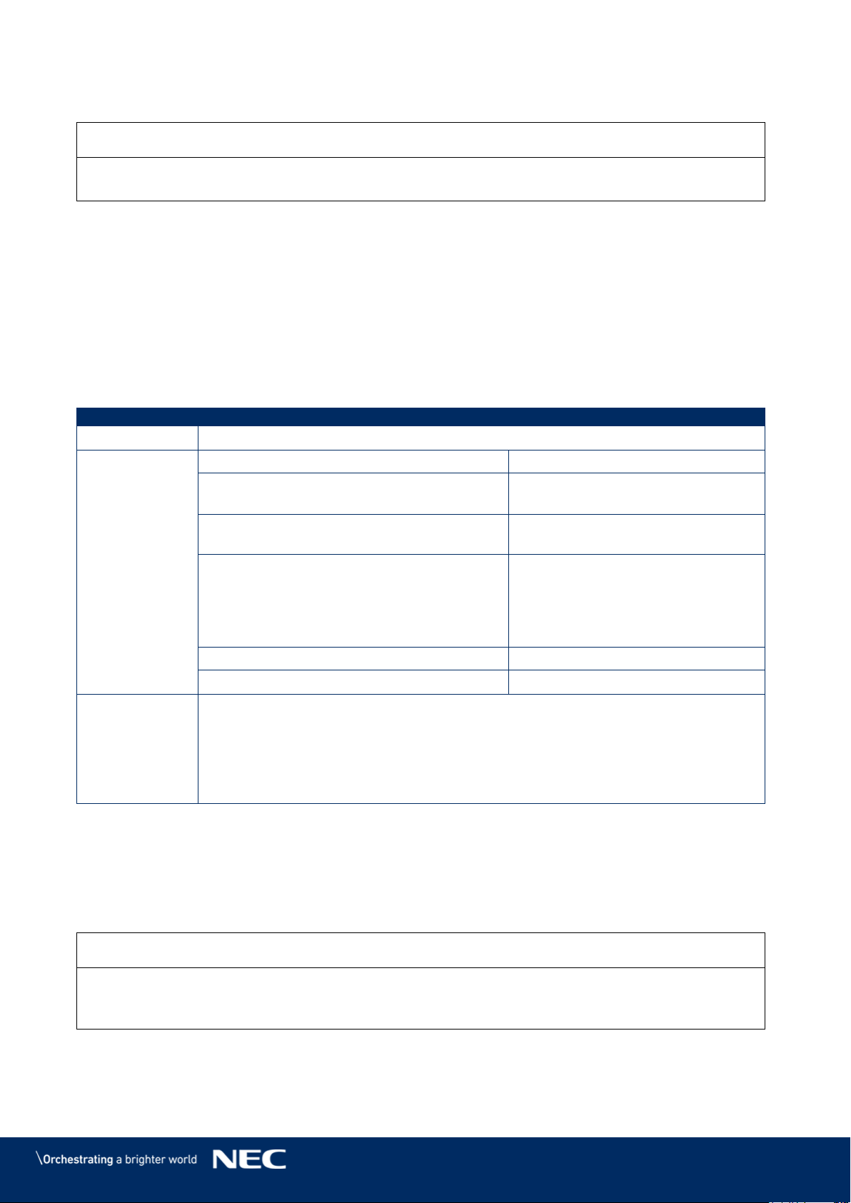
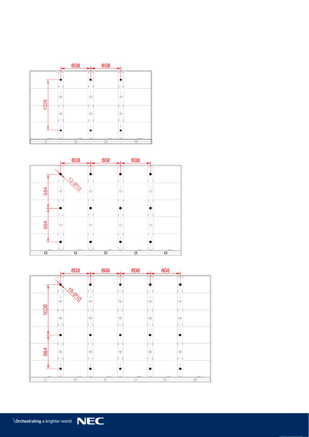
Draw and Mark the Anchor Positions on Wall 6.1.2
Start from the middle and mark the positions for the anchor points to drill out. (See markings
in figures below or the dimensions in Table 7.)
Use the spirit level to check the vertical alignment of the marks before drilling.
Figure 38: Positions for Anchor Points: 4×4 Frameset
Figure 39: Positions for Anchor Points: 5×5 Frameset
Figure 40: Positions for Anchor Points: 6×6 Frameset
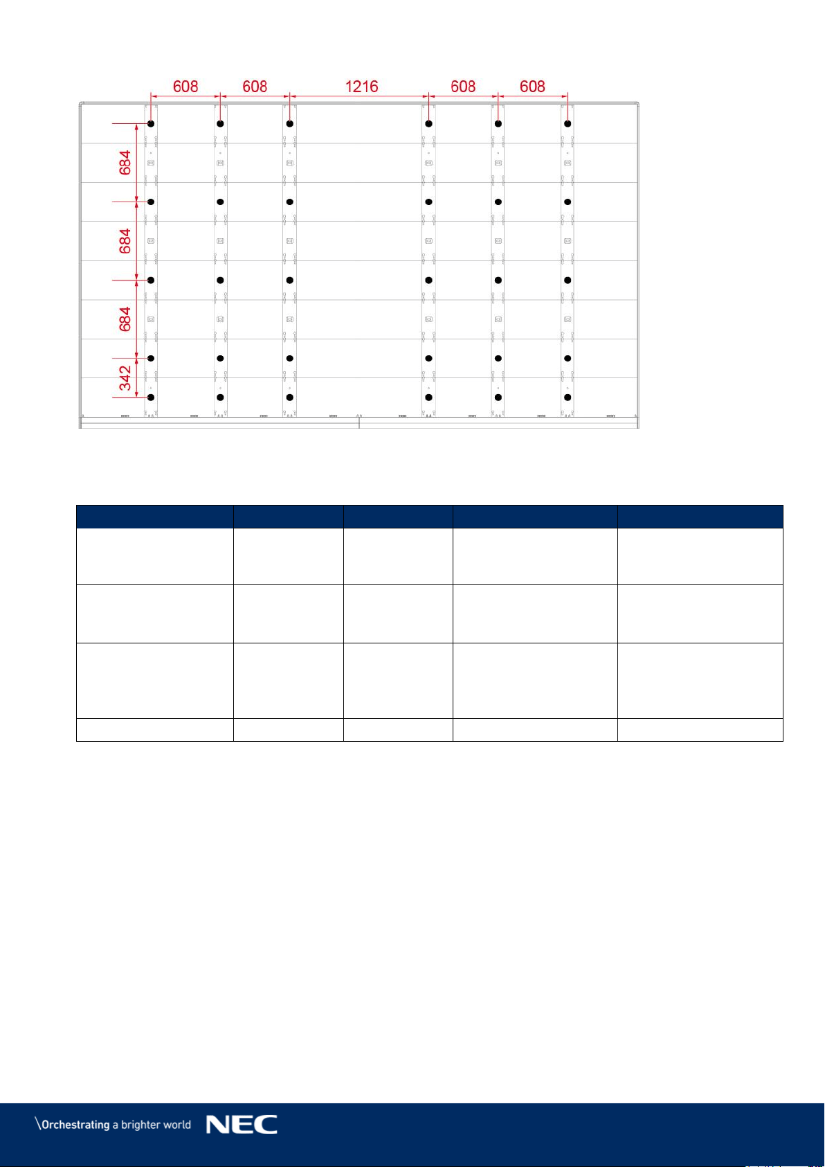
42
Figure 41: Positions for Anchor Points: 8×8 Frameset
Table 7: Number and Position for Anchor Points
Frameset:
4×4
5×5
6×6
8×8
Anchor Points
Horizontally ×
Vertically
3 × 2
4 × 3
5 × 3
6 x 5
Distance
Horizontally
608 mm
608 mm
608 mm
Distance center:1216
mm
Others: 608 equally
Distance Vertically
1026 mm
684 mm
equally
Distance top row –
middle row: 1026 mm
Distance middle row –
bottom row: 684 mm
Distance Bottom row:
342 mm, others 684
mm equally
Anchor size
Ø10 mm
Ø10 mm
Ø10 mm
Ø10 mm
Drill the Positions 6.1.3
Use required drilling equipment to drill on marked positions.
If necessary, use screw anchors / raw plugs.
Remove any debris and wipe away drill shaving and dust particles.
43
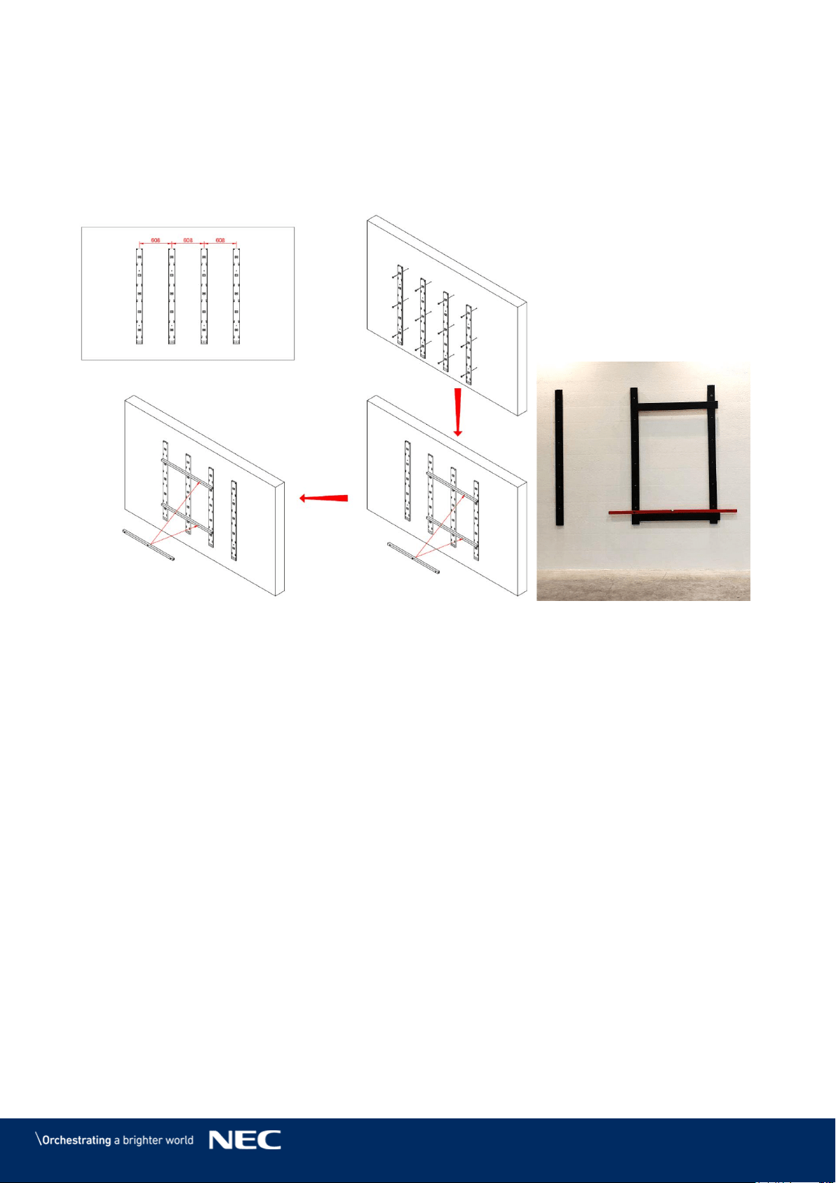
Attach the Mounting bars 6.1.4
Attach each vertical Mounting bar onto the grid on the wall. Step 1)
Check the distance of the frame elements using the Alignment bar. Step 2)
Use the spirit level together with the Alignment bar to check the evenness (Figure 42 Step 3)
and Figure 43). If necessary, adjust the positions accordingly.
Figure 42: Wall Mounting: Attachment of Mounting bars
(5×5 Frameset)
Figure 43: Using Alignment Bar
with Spirit Level
44
6.2
Install Power Bar onto Mounting bars
This section is a guide to mounting the Power bar onto the Mounting bars and describes the
following in more detail:
Prepare the Mounting bars so they are level.
Position the Power bar on the Mounting bars.
Then fix the Power bar onto the Mounting bars.
Table 8: Power Bar Installation Requirements
No. of People
2
Prerequisites
Mounting bar securely installed
Power bar/LED Wall not connected to mains
Tools
Alignment bar
Spirit level
Screwdriver
Equipment
Power bar
Check the Evenness 6.2.1
Use the Alignment bar and spirit level in combination to check the evenness between Step 1)
the vertical Mounting bars.
If necessary, adjust top and bottom supports accordingly. Step 2)
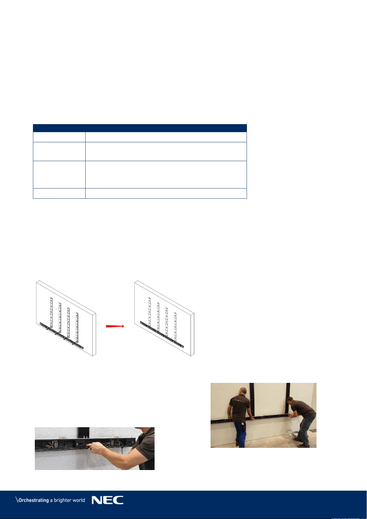
Bring Power Bar into Position 6.2.2
Bring the Power bar into position to align interface to anchoring point. Step 3)
Align the locating pin of the Power bar to the Mounting bar interface. Step 4)
Figure 44: Wall Mounting: Attachment of Power Bar (5×5 Frameset)
Attach Power Bar to Mounting bars 6.2.3
Use M6×12 Screws (4 per Mounting bar) to
Step 5)
attach Power bar onto the Mounting bars.
Check that the Power bar is level. If
Step 6)
necessary, adjust accordingly.
Tighten the screws.
Step 7)
Figure 45: Wall Mounting: Attachment of Power Bar (Detail)
45
6.3
Install Cabinets
This section is a guide to mounting the cabinets onto the Mounting bar and describes the following
in more detail:
Prepare the cabinets for installation.
Install the first row of cabinets
Fix the first row of cabinets to the Power bar.
Install further cabinets.
Align all cabinets of the LED Wall to achieve an even surface.
Table 9: Cabinet Installation Requirements
No. of People
2
Prerequisites
Frameset securely installed
Power bar securely installed
Tools
Screwdriver
Allen key
Equipment
Cabinets
Cabinet hanger pins
Adjustment plate
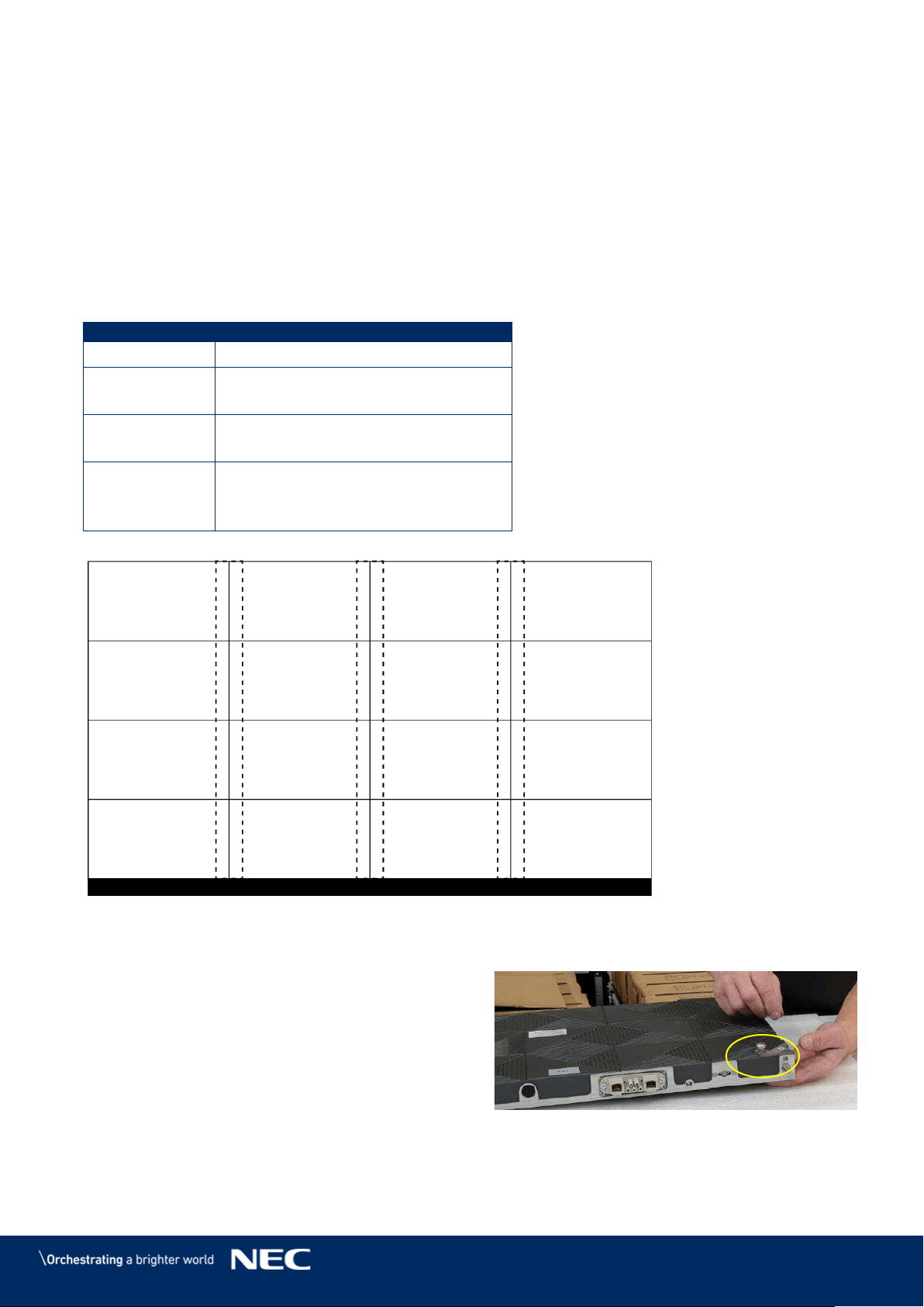
Figure 46: Wall Mounting: Installation Order of Cabinets (4×4 Frameset)
Install Cabinet Hanger Pins on the Backside 6.3.1
On the workbench, place cabinet front-side down
on a protected surface.
Install Cabinet hanger pins (2×) on top
Step 1)
left- and right-hand corners.
Secure the Cabinet hanger pins firmly.
Step 2)
Figure 47: Installing the Cabinet Hanger Pins
1
2
3
4
5
6
7
8
9
10
11
12
13
14
15
16
46
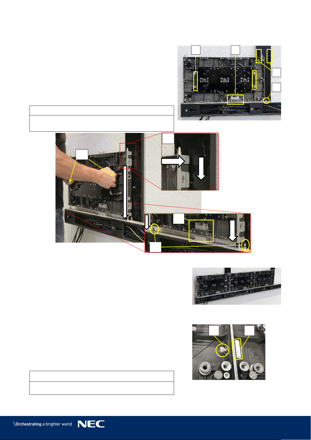
Install Cabinets for Bottom-Row on Power Bar 6.3.2
Use the grip handles on the cabinet (Figure
Step 1)
48, A) to bring it into position at left corner on
the Power bar.
Align together the Cabinet hanger pins with
Step 2)
the Mounting bar sockets (B) and the Corner
alignment pins on the Power bar (C).
Lower the cabinet onto the Power supply
socket (D), gently pressing it until it sits
firmly.
Notice
Place the cabinet carefully and straight on top of the
Power supply socket.
Figure 48: Installing the First Cabinet
Install further cabinets until the first row is
Step 3)
complete.
Figure 49: Installing Additional
Cabinets – First Row
Connect each cabinet to its adjacent cabinets with
Step 4)
the Screw connections.
Place a delivered Allen screw (E) in the screw
a)
connection anchor.
Only finger-tighten the screw to the Counter
b)
plate (F) in the other cabinet.
Figure 50: Locking Two Modules
Notice
Do not tighten the Screw connection too much.
Otherwise the cabinets cannot be aligned later on.
C
A
B
D
A
C
B
D
E
F
47
Figure 51: Cabinet Screw Connections: Counter plates (H), Allen Screw anchors (I)
Adjust the vertical alignment of the cabinets using the screw in the top corner of the
Step 5)
cabinet.
Figure 52: Vertical Alignment of Cabinets
Secure Cabinet to Power Bar 6.3.3
Connect the cabinets of the first row to the Power bar. For this, screw a M8×16 screw Step 1)
in the opening for the Screw connection at the bottom of the cabinets
Screw the cabinets of the first row onto the Power bar with M8×16 screws. Step 2)
Figure 53: Fastening of First Row to Power Bar
I
H
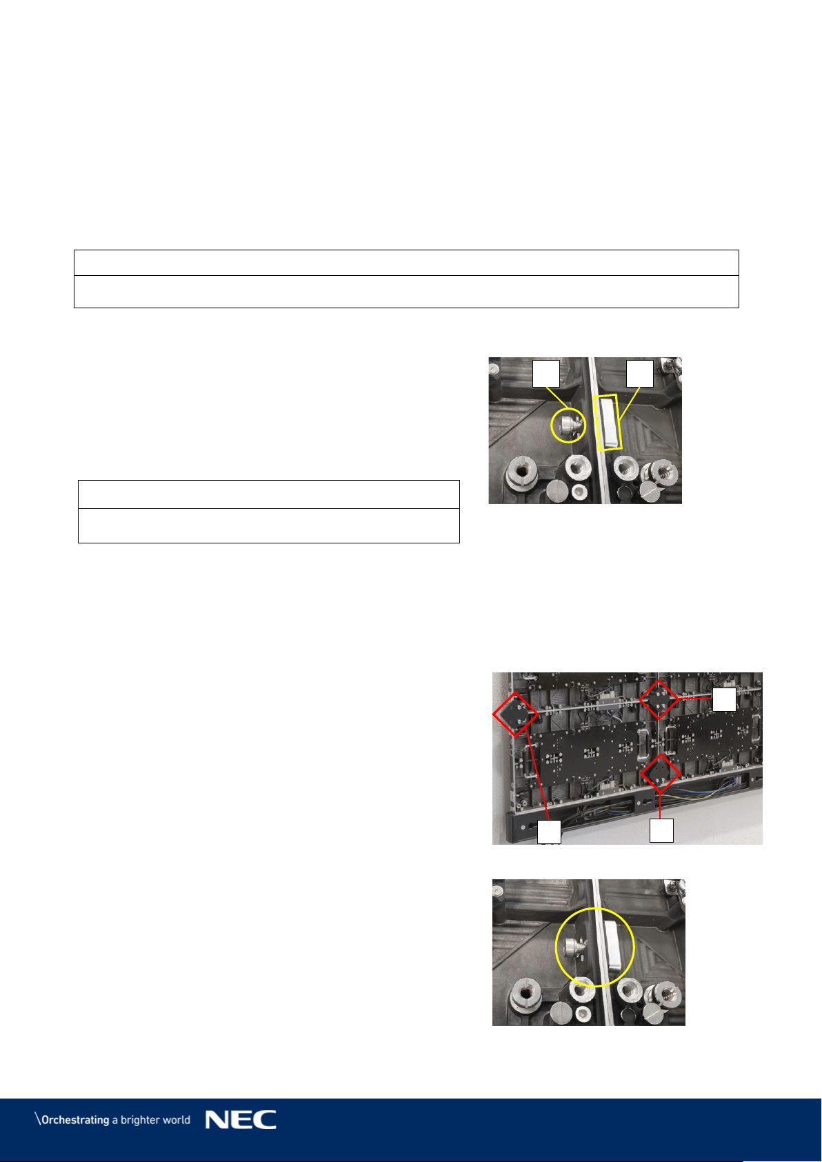
48
Install Further Cabinet Rows 6.3.4
Install the Cabinet hanger pins (see 6.3.1). Step 1)
Use the grip handles on the cabinet (Figure 48 in chapter 6.3.2, A) to bring it into Step 2)
position at left corner on the first cabinet row.
Align together the Cabinet hanger pins with the Mounting bar sockets (Figure 48, B) Step 3)
and the Corner alignment pins on the cabinet below (Figure 48, C).
Lower the cabinet onto the Power supply socket (Figure 48, D), gently pressing it until
it sits firmly.
Notice
Place the cabinet carefully and straight on top of the Power supply socket.
Install further cabinets until a row is complete. Step 4)
Connect each cabinet to its adjacent cabinets
Step 5)
with the Screw connections.
Place a delivered Allen screw (E) in the
a)
screw connection anchor.
Only finger-tighten the screw to the
b)
Counter plate (F) in the other cabinet.
Figure 54: Locking Two Modules
Notice
Do not tighten the Screw connection too much.
Otherwise the cabinets cannot be aligned later on.
For the top row, use type B cabinets only.
Step 6)
Proceed as described above.
Align Cabinets 6.3.5
After all rows of cabinets are installed, the cabinets have to be aligned with the Adjustment
plates.
For each cabinet junction, attach one
Step 1)
Adjustment plate (A) with four screws, one on
each cabinet.
Attach Adjustment plates also on the sides of
Step 2)
the LED Wall (B) and at the bottom over the
Power bar (C).
Figure 55: Adjustment plates
After each cabinet junction has a Adjustment
Step 3)
plate, tighten all Screw connections hand tight.
By tightening the Screw connections properly,
the cabinets keep their aligned position.
Remove all Adjustment plates.
Step 4)
A
C
B
E
F
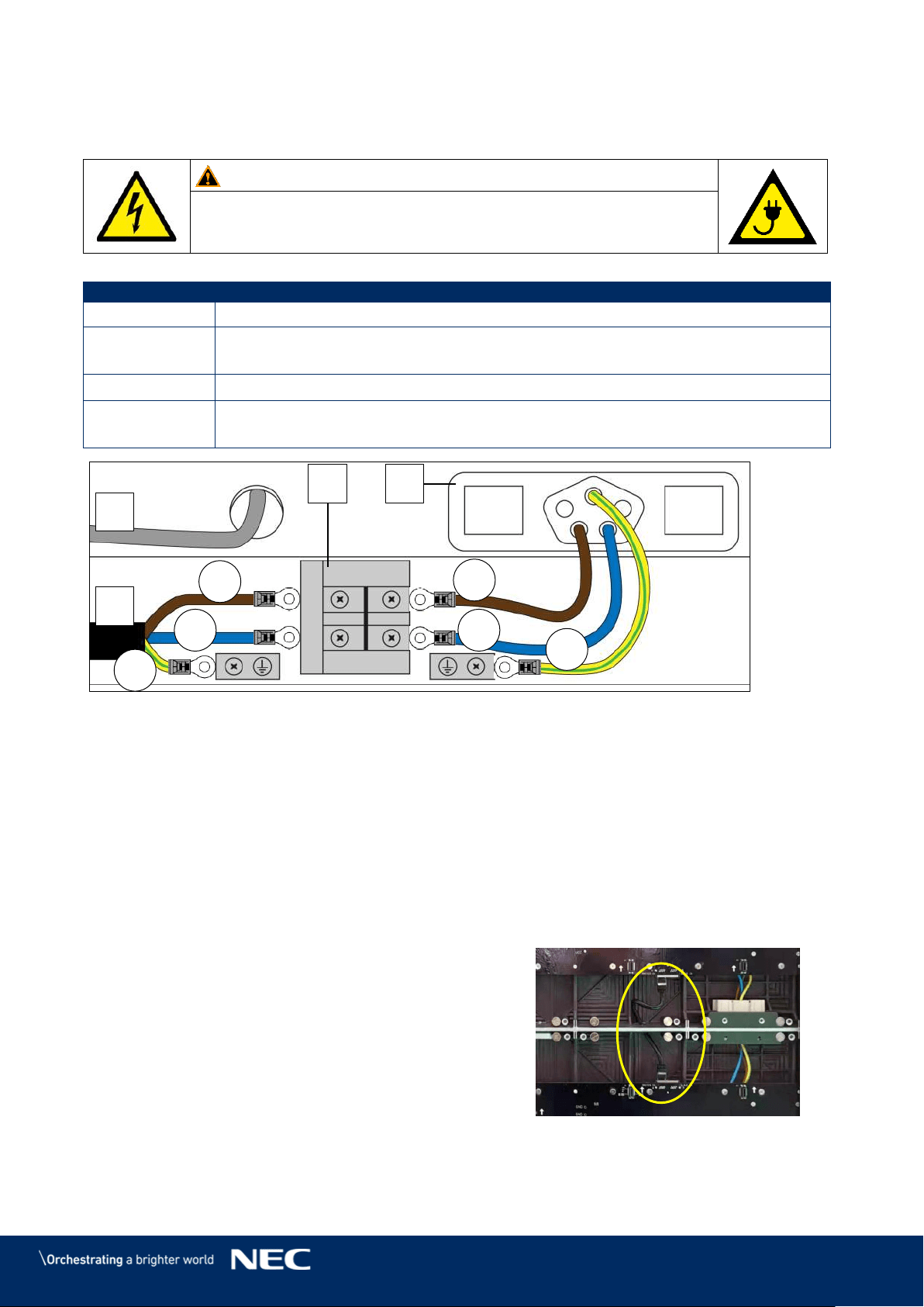
49
6.4
Connect Power and Data Cables
This section is a guide to power in the Power bar and the data connection to the Hub boards
Warning!
Only trained personnel, such as electricians or NEC personnel, may
connect the internal power supply to mains power supply.
Table 10: Cable Connection Requirements
No. of People
1
Prerequisites
Cabinets securely installed
Mains power not connected
Tools
Screwdriver
Equipment
External power cable (not included in delivery)
Data cables from LED Wall to NovaStar Controller (Cat cable, FTP Cat5e)
Figure 56: Connections in Power Bar
A
External power input
C
Power supply socket in Power bar
B
Terminal in Power bar
D
Data cable
Connect Data Cables 6.4.1
Prepare the data connection according to the cabling plans, see 15.1 Cable Plans.
Step 1)
Each column of cabinets needs one data input cable from the video controller.
Run the data cable (see Figure 56, D) from the video controller through the Power bar
Step 2)
to the first Hub board of a column.
Push the cable through the hole in the Power bar.
Connect the data input to the left Ethernet ports on the Hub board.
Step 3)
From the first Hub board, connect the short
Step 4)
CAT cable to the next Hub board in the
cabinet above.
Push the cable through the hole in the
cabinet.
Repeat this procedure for the rest of the
Step 5)
cabinets and cabinet rows.
Figure 57: Connecting Two Cabinets
C
B
A
D
L
PE
PE
N
N
L
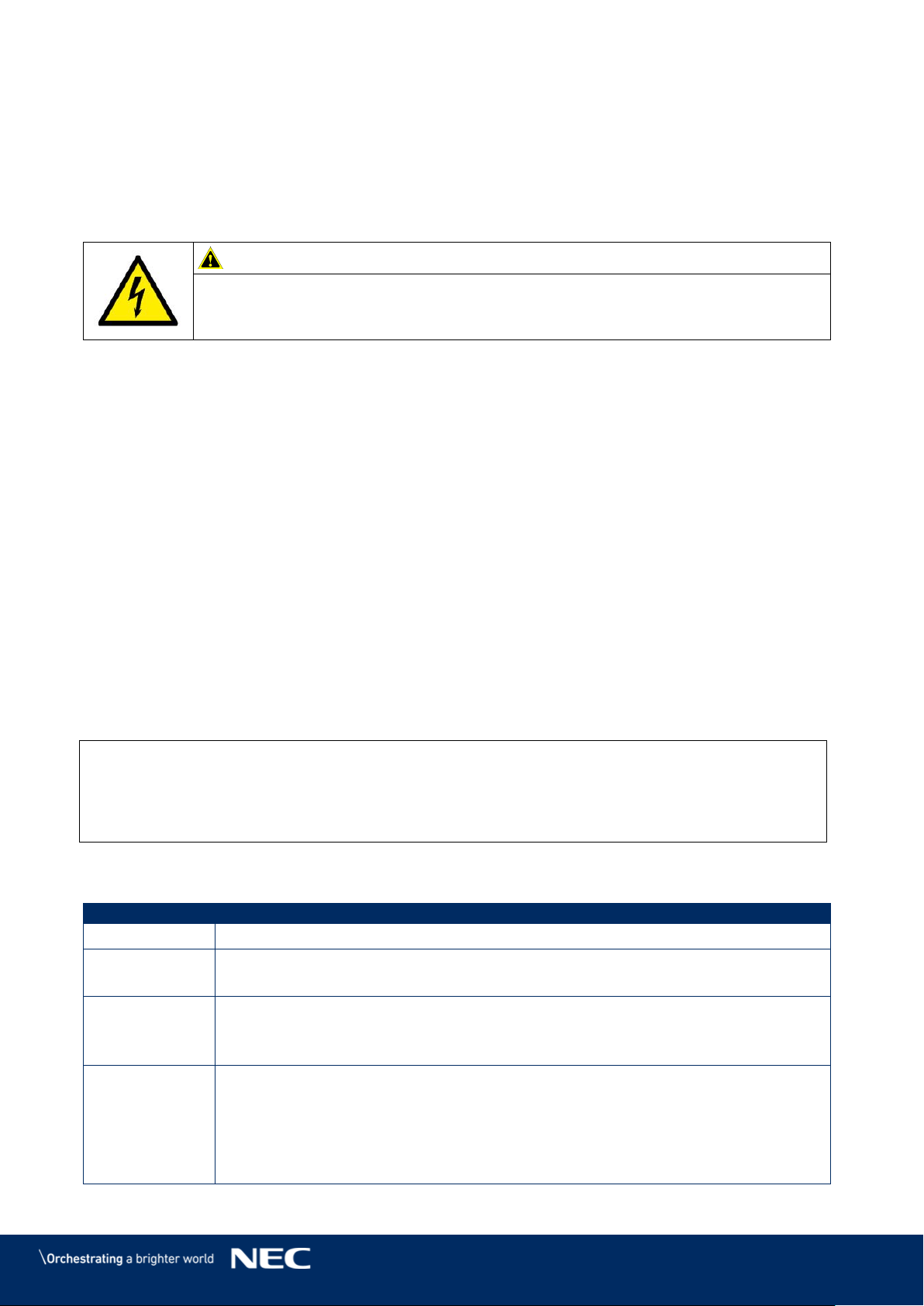
50
Connect Power Cables to the Power Bar 6.4.2
Prepare the power connection according to the cabling plans, see 15.1 Cable Plans. Step 1)
Each column of cabinets is wired to one terminal in the Power bar.
Connect the conductors of the external power cables (L, N, PE) to the terminals in the Step 2)
Power bar. See also Figure 56.
Connect each conductor (L, N, PE) to its appropriate terminal (L, N, PE). The coloring
and the positions may differ from Figure 56.
Caution!
Risk of electric shock and product damage.
Ensure the Power bar and the whole LED Wall are properly grounded before
putting it into use.
Check the Power Supply and Data Connection of the Modules 6.4.3
With the NovaLCT software, you can check whether the power supplies of each module work
properly and whether the data transmission between the cabinets works properly.
Install the Software, see 7.2 Install Controller Software NovaLCT. Step 1)
Load the screen files, see 7.3 Configure the Screen in NovaLCT. Step 2)
Connect the LED Wall to mains or turn it on. Step 3)
Follow 8.3 Monitoring, section 8.3.2 to 8.3.3. Step 4)
If you find an error, check the wiring and the connection of the Power supply sockets.
Separate the LED Wall from mains power to continue safely with the installation. Step 5)
6.5
Install Overframes and Power bar cover
The Overframes protect the LED Wall from any dust or other particles that could come in through
the holes on the sides and the top.
Inside the Overframes are slot nuts. The Overframes are attached to the LED Wall via screws,
which go through the Screw connection anchors into the slot nuts.
Info
It is easier to install the Overframes first and later the Pixel cards. However, if the Pixel cards
are already installed, only a few Pixel cards need to be taken out to install the Overframes. The
pictures also show the procedure with installed Pixel cards.
This section is a guide through the assembly of the frame and its installation on the LED Wall.
Table 11: Overframe and Power bar cover Installation Requirements
No. of People
2
Prerequisites
Cabinets
Enough space in front of LED Wall to assemble frame
Tools
Screwdriver
Allen key
Service tool
Equipment
Frame covers:
Corner frame bottom (left, right)
Overframe (left, right) (LED Wall)
Overframe (top)
Corner frame top (left, right)
Power bar cover
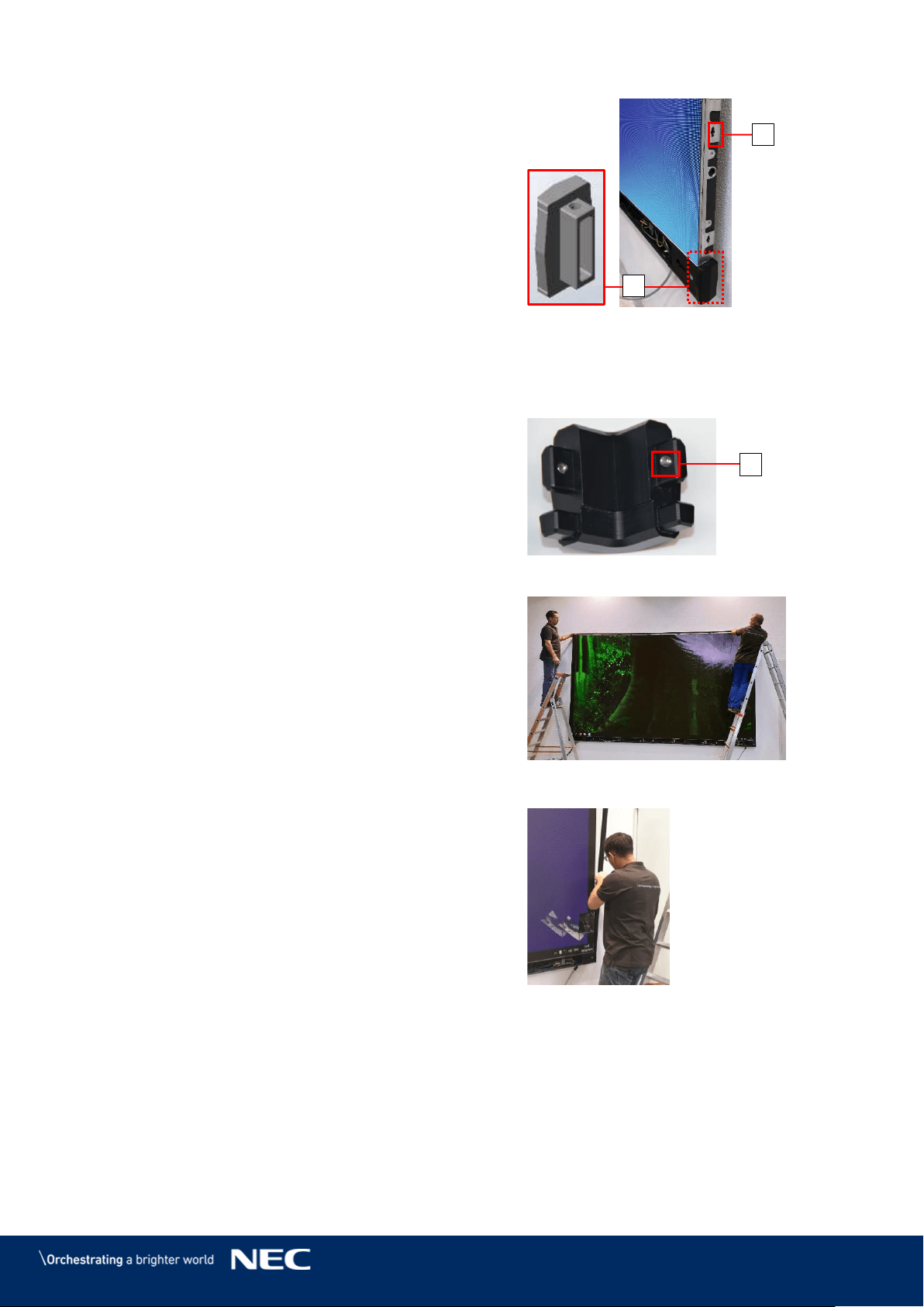
51
Attach the Corner frame bottom (left, right)
Step 1)
(A) to the Power bar on both sides.
If the Pixel cards are already installed:
Step 2)
Place the Overframes (left, right) next to the
edge of the LED Wall.
With the Service tool (Figure 101, p. 76),
remove those Pixel cards that cover the
Screw connection anchors (B) that connect
to the Overframes (left, right).
You need to have access to the Screw
connection anchors (B) from the inside of
the cabinet.
Figure 58: Installing Corner frame
bottom (left, right)
Before mounting the Overframes on the LED Wall, assemble the frame on the ground
Step 3)
in front of the LED Wall.
Attach the Corner frame top (left, right) to
Step 4)
the Overframe (top) with the pre-installed
screw (D).
Attach the Overframes (left, right) to the
Step 5)
Overframe (top) and links with the
pre-installed screw (D)
Figure 59: Corner frame top (left, right)
With two people, carefully lift the
Step 6)
Overframes and place it onto the LED Wall.
Figure 60: Installing Overframe (top)
Align the slot nuts in the Overframes with the
Step 7)
Screw connection anchors.
Ensure there is no gap between the
Overframes (left, right) and the Corner frame
bottom (left, right).
Figure 61: Installing Overframe (left,
right)
A
B
D
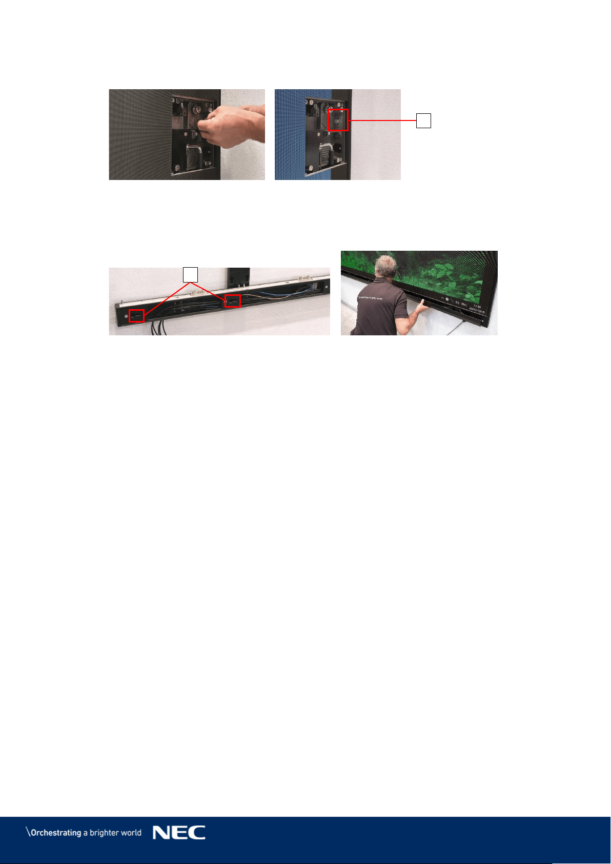
52
Attach the Overframes (left, right) to the LED Wall by screwing the M8×16 screws (C)
Step 8)
through the Screw connection anchors into the slot nuts.
Figure 62: Fastening the Overframe (left, right)
Slide the hooks on Power bar cover plate into the vertical key holes (E) on the Power
Step 9)
bar.
Push the Power bar cover plate firmly to the right so it stays in place.
Figure 63: Installing Power Bar Cover Plate
C
E
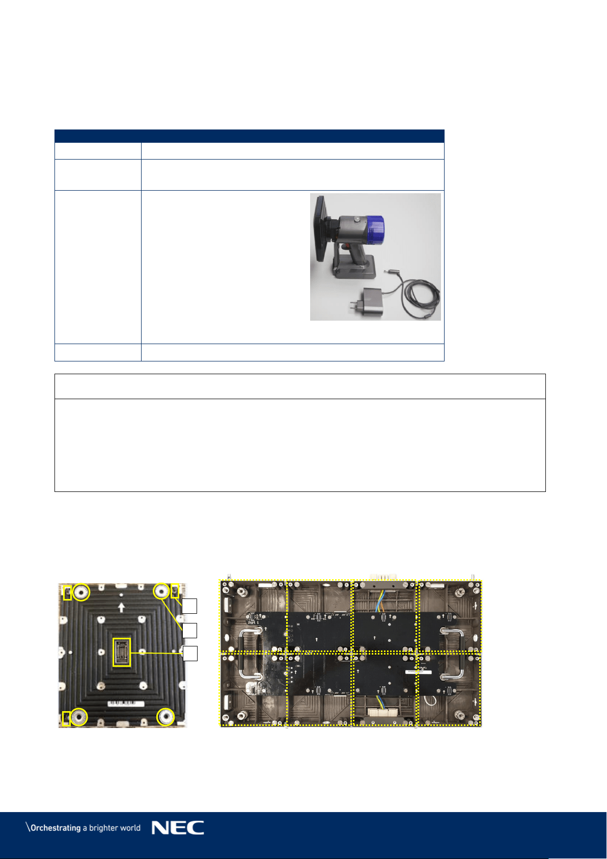
53
6.6
Install Pixel Cards
This section is a guide to the installation of the Pixel cards.
Table 12: Pixel Card Installation Requirements
No. of People
1
Prerequisites
Cabinets installed, levelled, locked and connected
Check to ensure Power supply & Ethernet are connected
Tools
ESD gloves
Service tool
Figure 64: Service Tool
Equipment
Pixel cards
Notice
Use the included white ESD gloves when handling Pixel cards to prevent static electricity from
the human body and contamination due to finger oils, perspiration salts, flaking skin, and/or
other forms of human excretory secretions.
The LED modules and their electrical components are sensitive to biological agents and exposure
to such risks degradation of materials and performance.
Eliminate any static electricity from your body before touching the Pixel cards by touching an
aluminum sash, a door knob, or some other metal object.
Pixel cards use a combination of magnets (Figure 65, B), corner click-pins (A) and the Pixel card
connector (C) to attach to the cabinets.
No cable connections are required to install Pixel cards.
Install the Pixel cards in the locations indicated in Figure 66. Follow the steps below.
Figure 65: Pixel Card
Figure 66: Pixel Card Positions in a Cabinet
A
B
C
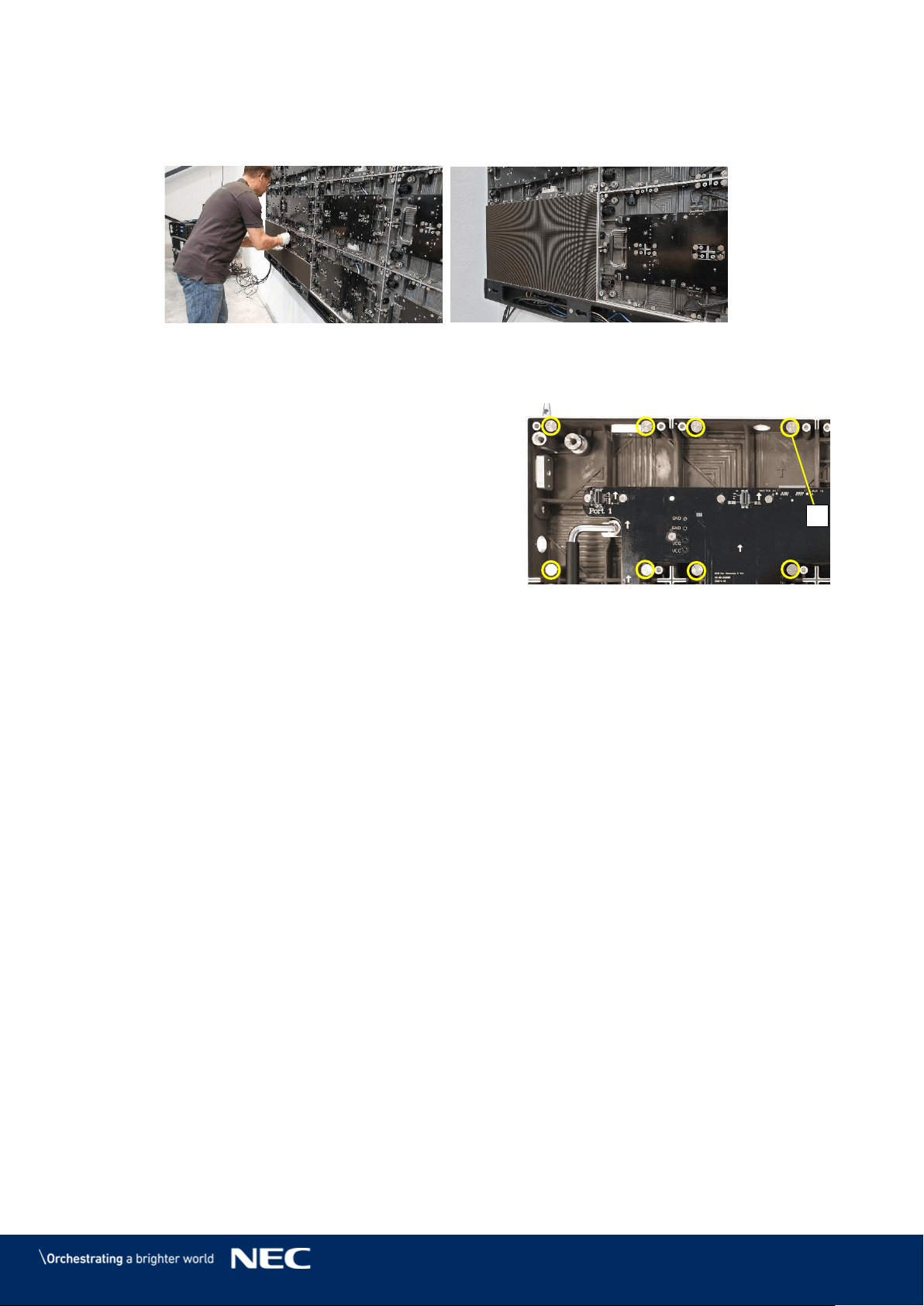
54
Remove the Adjustment plates. Step 1)
Install the Pixel cards. Step 2)
Mount 4 × 2 Pixel cards onto each cabinet. Start with the bottom row, then top row.
Figure 67: Installing the Pixel Cards
Ensure that the surface of the LED Wall is even. Step 3)
If a Pixel card sticks out, minimize the
Step 4)
protrusion with the level screws (A) in the
cabinet.
Remove the Pixel card with the Service
a)
tool (Figure 101, p. 76).
Adjust the level screws in the cabinet.
b)
Re-install the Pixel card and check if it is
c)
level to the other Pixel cards.
Figure 68: Level Screws
The LED Wall is completely installed.
A
55
7
GETTING STARTED
After mounting the LED Wall, check all cable connections and ensure they are connected
according to 15.1 Cable Plans. The cable plans also include the connection between a computer
and the NovaStar Controller.
7.1
Info on the Connection Setup
Warning!
Only trained personnel, such as electricians or NEC personnel, may
connect the internal power supply to mains power supply.
Power input for the LED Wall is provided by connecting the Power bar to the electric power system
of the building. Ensure there is a possibility to switch the power for the LED Wall on and off.
Data input is provided by connecting the Power bar to a NovaStar Controller. The NovaStar
Controller is connected to a content computer, which provides the content data, and to a service
computer, which provides data about how the content is displayed on the screen.
Notice
The NovaStar Controller is no product of NEC DISPLAY SOLUTIONS.
For detailed information on the NovaStar Controller, see the respective manual for
NovaStar Controller MCTRL660 PRO. Download the current version at:
https://www.novastar.tech/download/download-controller/
7.2
Install Controller Software NovaLCT
To configure and check the functions of the controller, you need to install the software NovaLCT.
The software installation package is delivered via USB flash drive.
The software allows you to perform screen configuration, brightness adjustment, calibration,
display control, monitoring, etc. To install the software, follow the steps below:
Connect the delivered USB flash drive to your computer. Step 1)
Open the USB flash drive. Step 2)
Navigate to the executable installation file NovaLCT.exe. Step 3)
Click the NovaLCT.exe file to start the installation of the software. Step 4)
Follow the instructions of the installation wizard to complete the software installation. If Step 5)
the firewall prompt appears, allow the installation.
Notice
Deactivate the antivirus software during the installation.
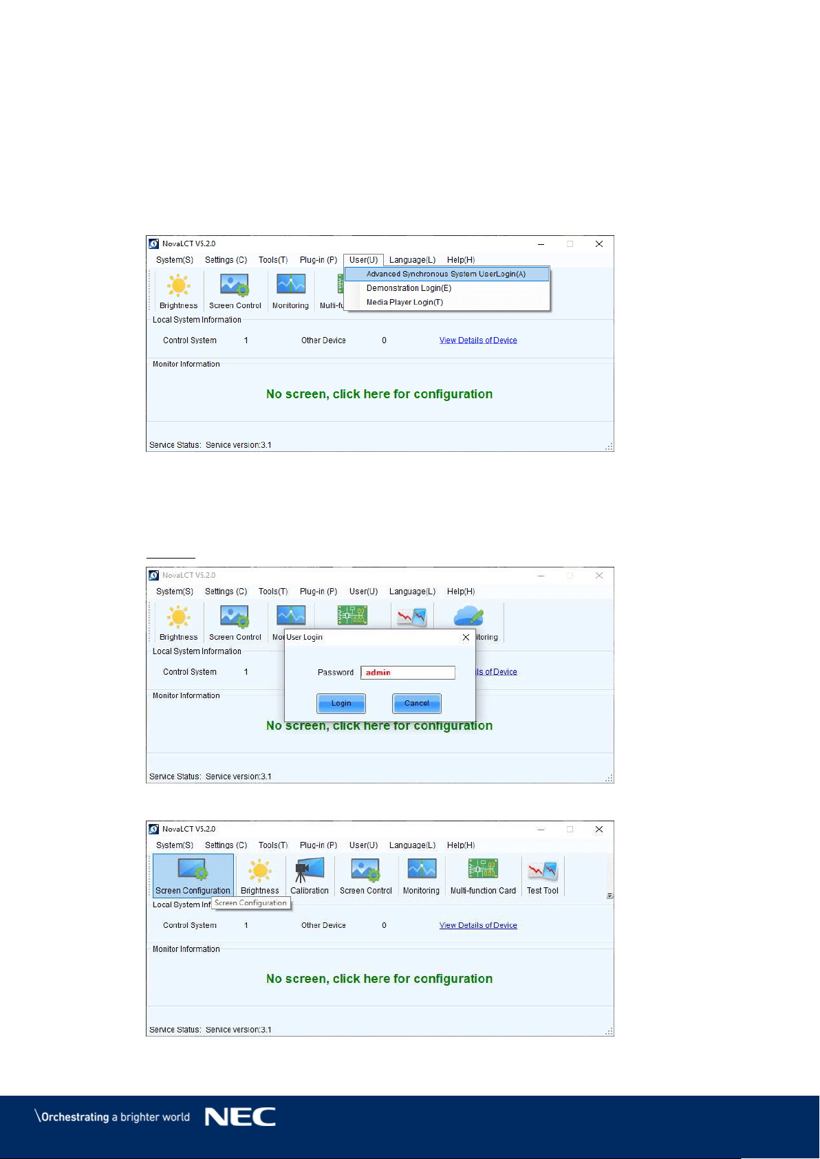
56
7.3
Configure the Screen in NovaLCT (Loading scr-Files)
The software installation package includes a defined Configuration setup. Before you finish the
installation of the LED Wall, you have to configure the Sending cards, the Receiving cards and the
Calibration Settings.
Start the software NovaLCT. Step 1)
Click the User(U) register and select Advanced Synchronous System User Step 2)
Login(A) (see Figure 69).
Figure 69: Advanced User Login
Enter the password into the Password field. The default password is admin. Step 3)
Click the Login button to confirm the entry (see Figure 70). The start screen refreshes
automatically.
Result: If the login is successful, the interface below will appear (see Figure 71).
Figure 70: Entering Password
Figure 71: Interface after Successful Login
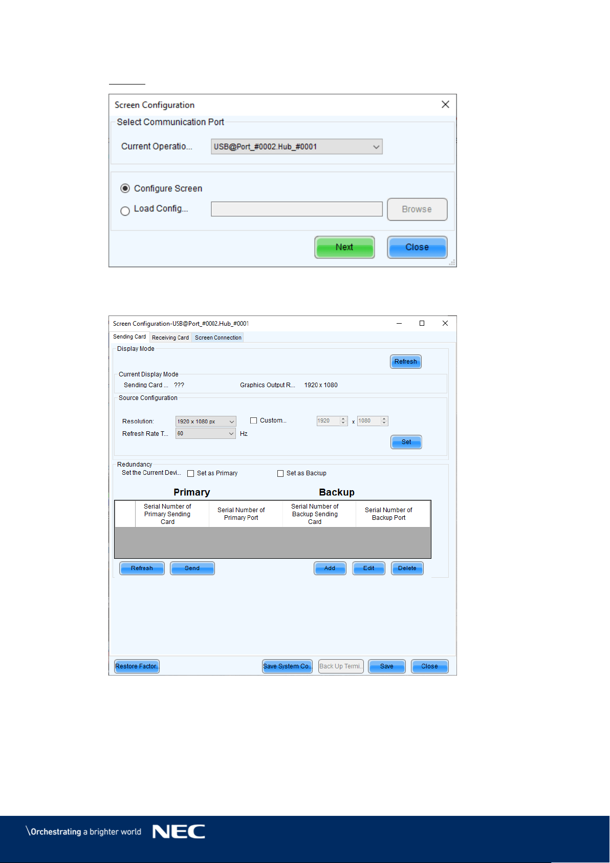
57
Click the Screen Configuration menu button. Step 4)
Result: Screen Configuration opens. The pop-up opens (see Figure 72):
Figure 72: Pop-Up Configurating the Screen Connection
Click the Next button. The screen refreshes (see Figure 73). Step 5)
Figure 73: Start Screen Configuration – Register Sending Card (Default View)
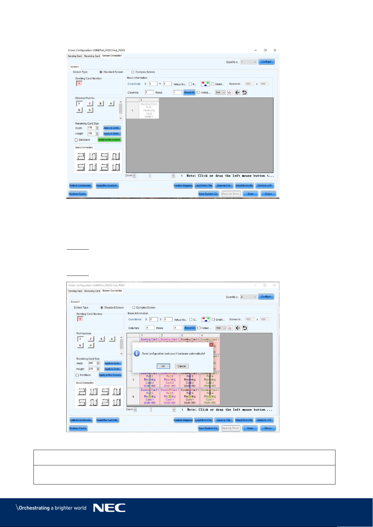
58
Switch from Sending Card tab to Screen Connection tab (see Figure 74). Step 6)
Figure 74: Start Screen – Screen Connection (Default View) before Configuration
Click the Load from file button (see Figure 74). Step 7)
Select the scr-file from the delivered USB flash drive and click Open button, confirm Step 8)
the loading message with OK button.
Result: The scr-file will be loaded.
Click the Send to HW button to save the configuration. Confirm the upcoming pop-up Step 9)
message with OK.
Result: The scr-file will be saved. After restart, the configuration is available.
Figure 75: Save Configuration
Notice
If you do not save the configuration, the system will start with the default settings.
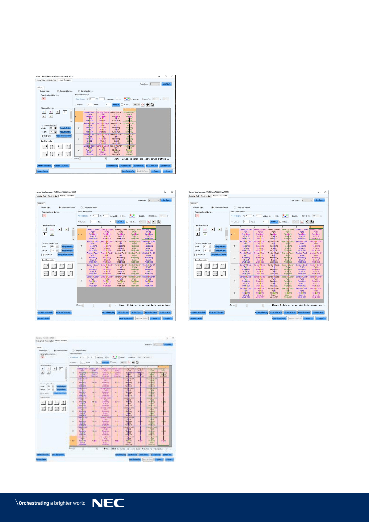
59
Screen Setup is finished. See the settings for each bundle below (see Figure 76 and
Figure 77).
Close the software by clicking X button or the Close button.
Step 10)
Settings for bundles 4×4, 5×5 and 6×6
Figure 76: Screen Settings for 4×4 Controller
Figure 77: Screen Settings for 5×5 Controller (left) and 6×6 Controller (right)
Figure 78: Screen Settings for 8×8 Controller
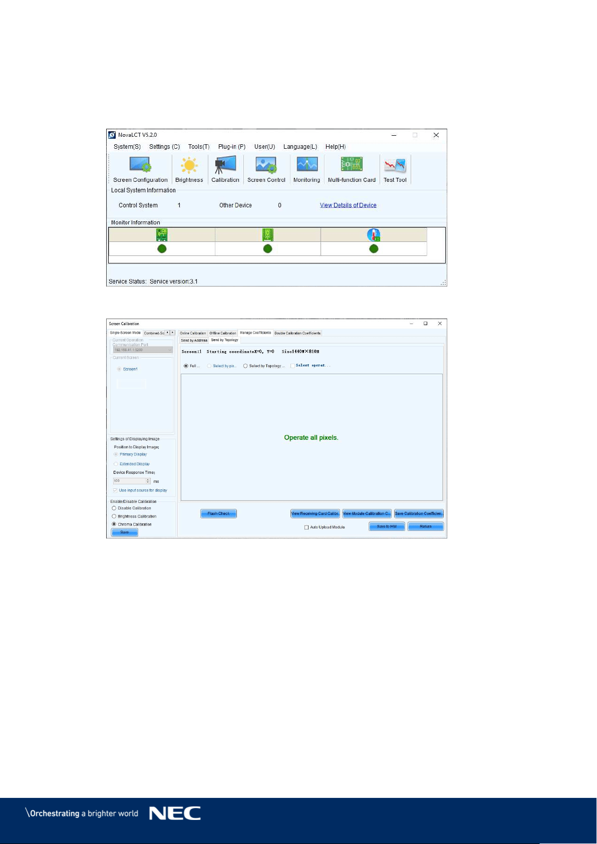
60
7.4
Update the Calibration Data after Installing All Pixel Cards
Login as Advanced User.
Step 1)
Click the Calibration button. The screen refreshes automatically (see Figure 79 and Step 2)
Figure 80).
Figure 79: Start Screen – Starting Calibration
Figure 80: Start Screen for Screen Calibration
Select the Screen1 radio button. Step 3)
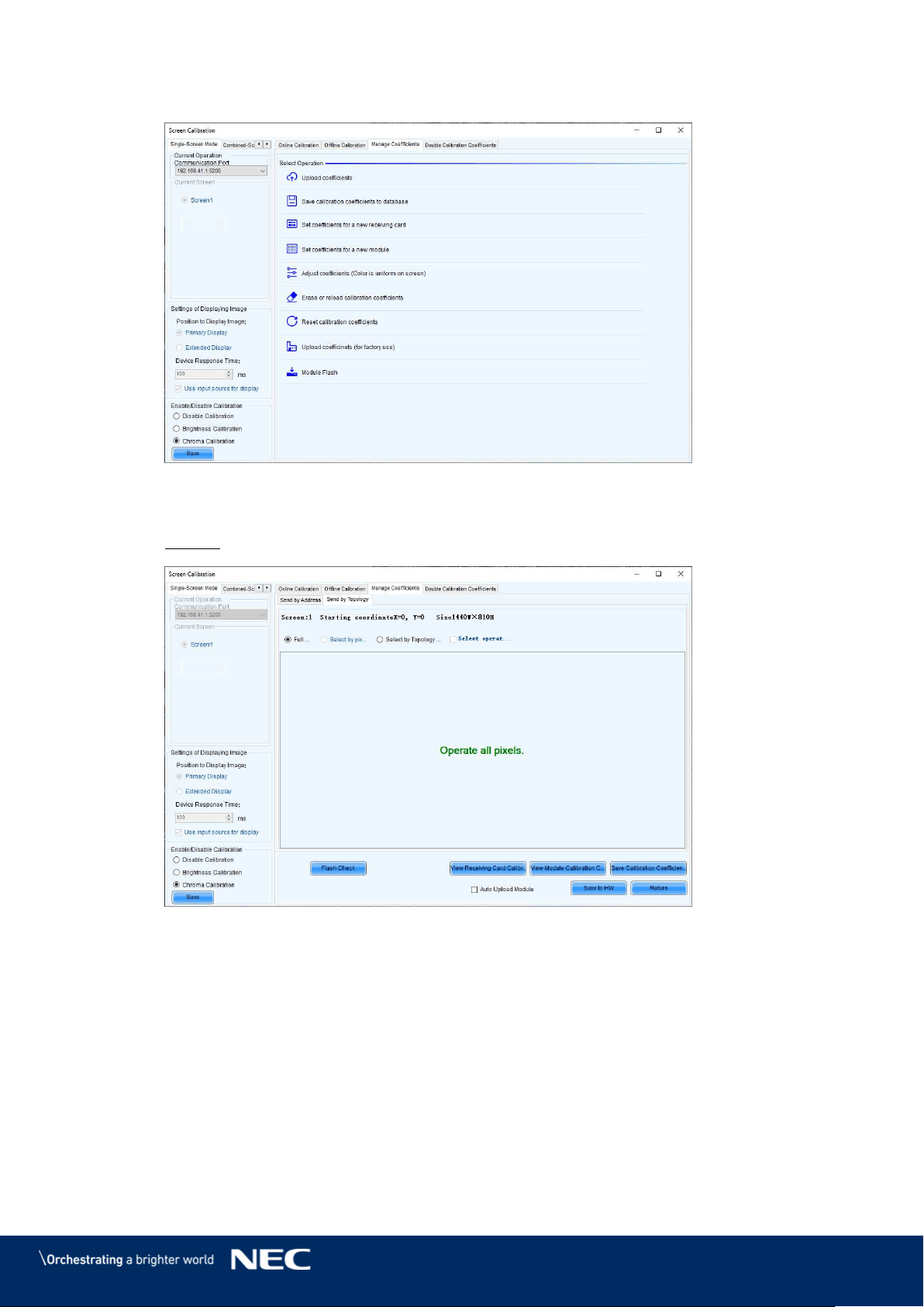
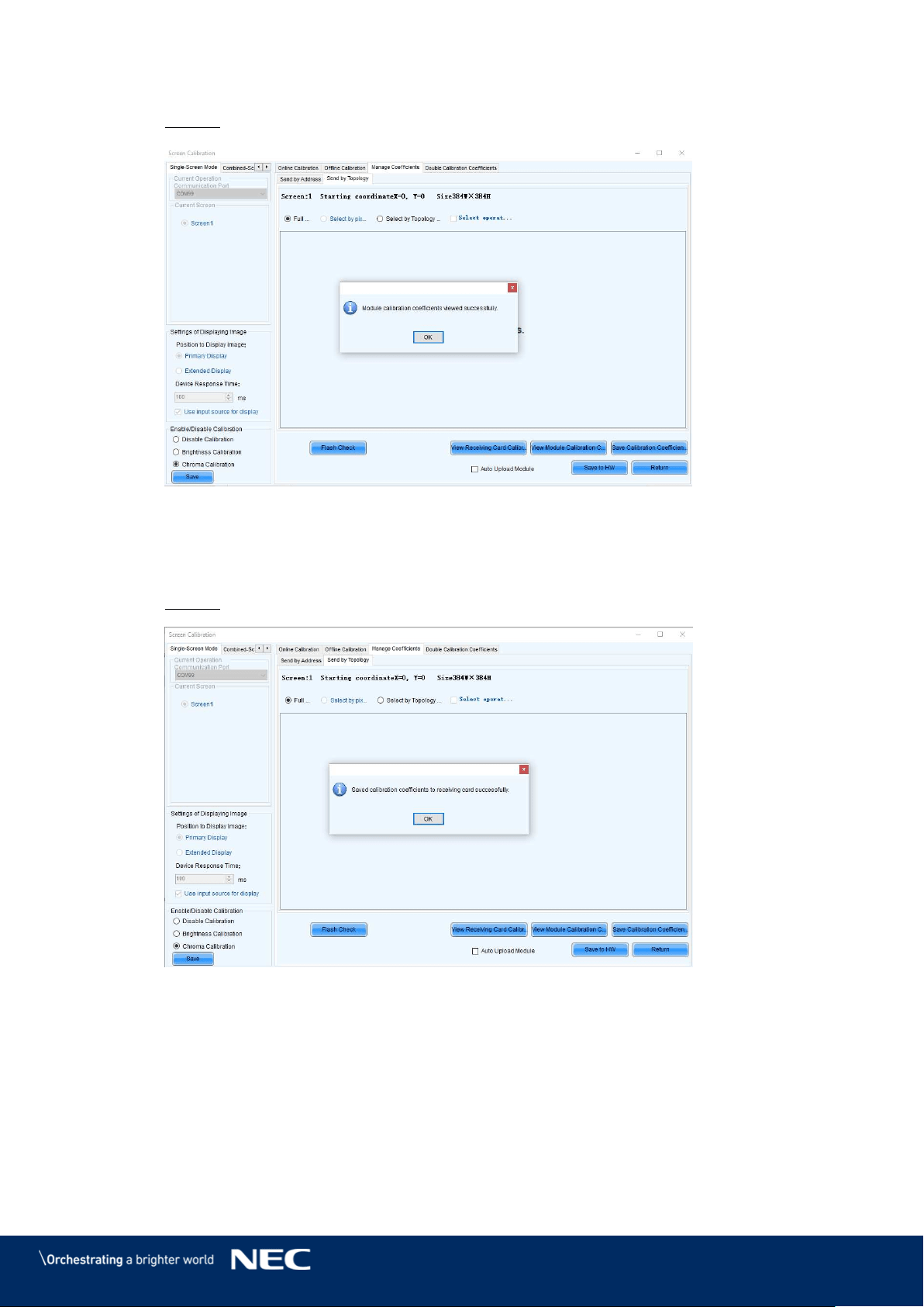
62
Click the View Module Calibration Coefficients button. Step 6)
Result: Pop-up message opens (see Figure 83).
Figure 83: Flash Module after loading Module Calibration Data
Click Save Calibration Coefficients to Receiving Card. Step 7)
The pop-up message, that the data has been successfully stored to the Receiving cards,
will appear (see Figure 84).
Result: The screen with the exchanged Pixel cards should look calibrated now.
Figure 84: Flash Module after saving Module Calibration Data
Click on Save to HW button and go back to main window by clicking X button. Step 8)
Repeat all steps for Screen 2. Click on the Return button to be able to select Screen 2 Step 9)
and re-open Module Flash
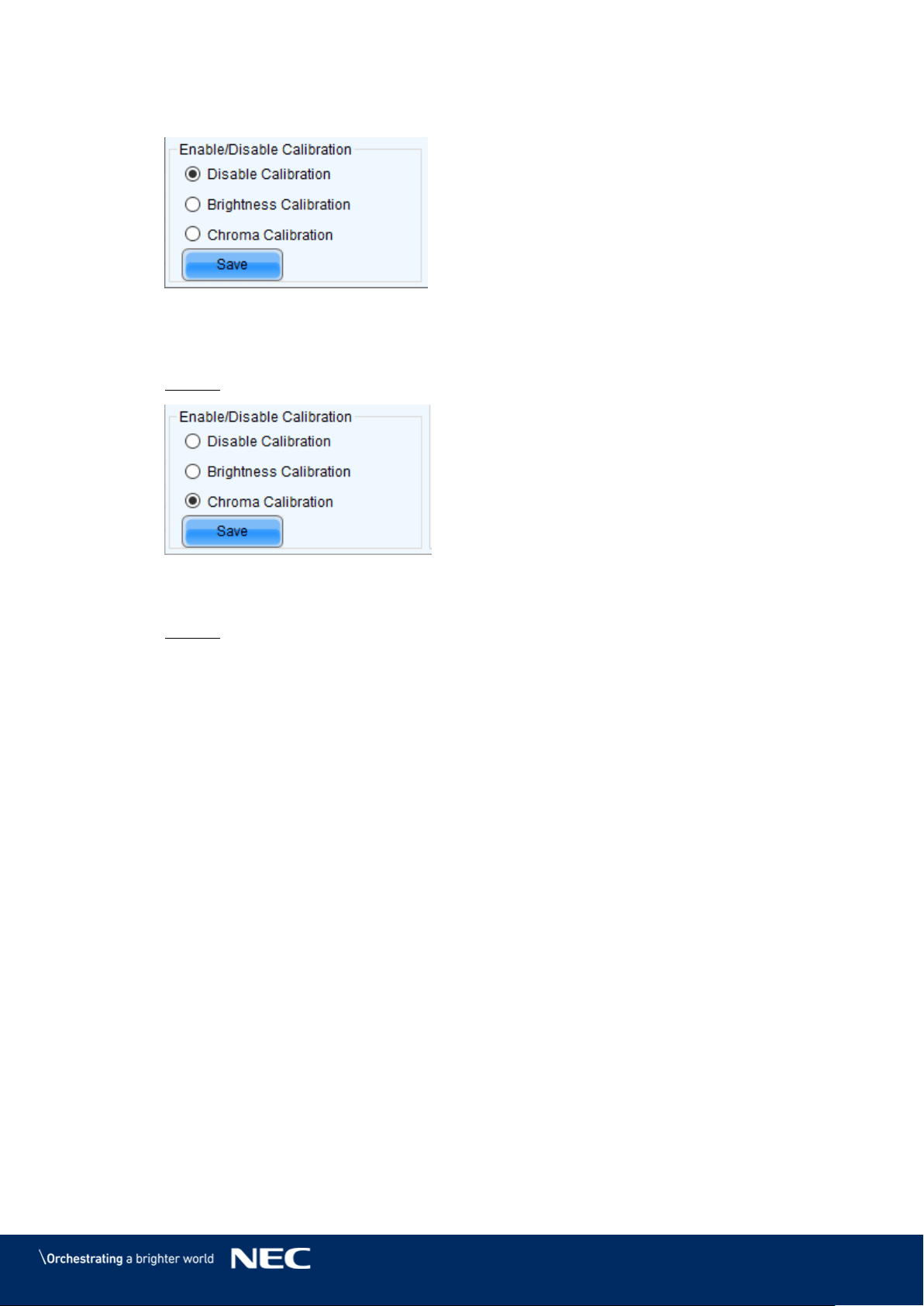
63
Check the calibration-state in the bottom left corner of Screen Calibration window: Step 10)
Enable/Disable Calibration (see Figure 85).
Figure 85: Calibration is disabled
If calibration-setting Disable Calibration is chosen, switch to Chroma Calibration to Step 11)
enable calibration and click on the Save button (see Figure 86).
Result: While switching you will already see calibration effect.
Figure 86: Calibration is enabled
Close Screen Calibration windows by clicking on the X. Step 12)
Result: The Screen Calibration has been finished for both screens.
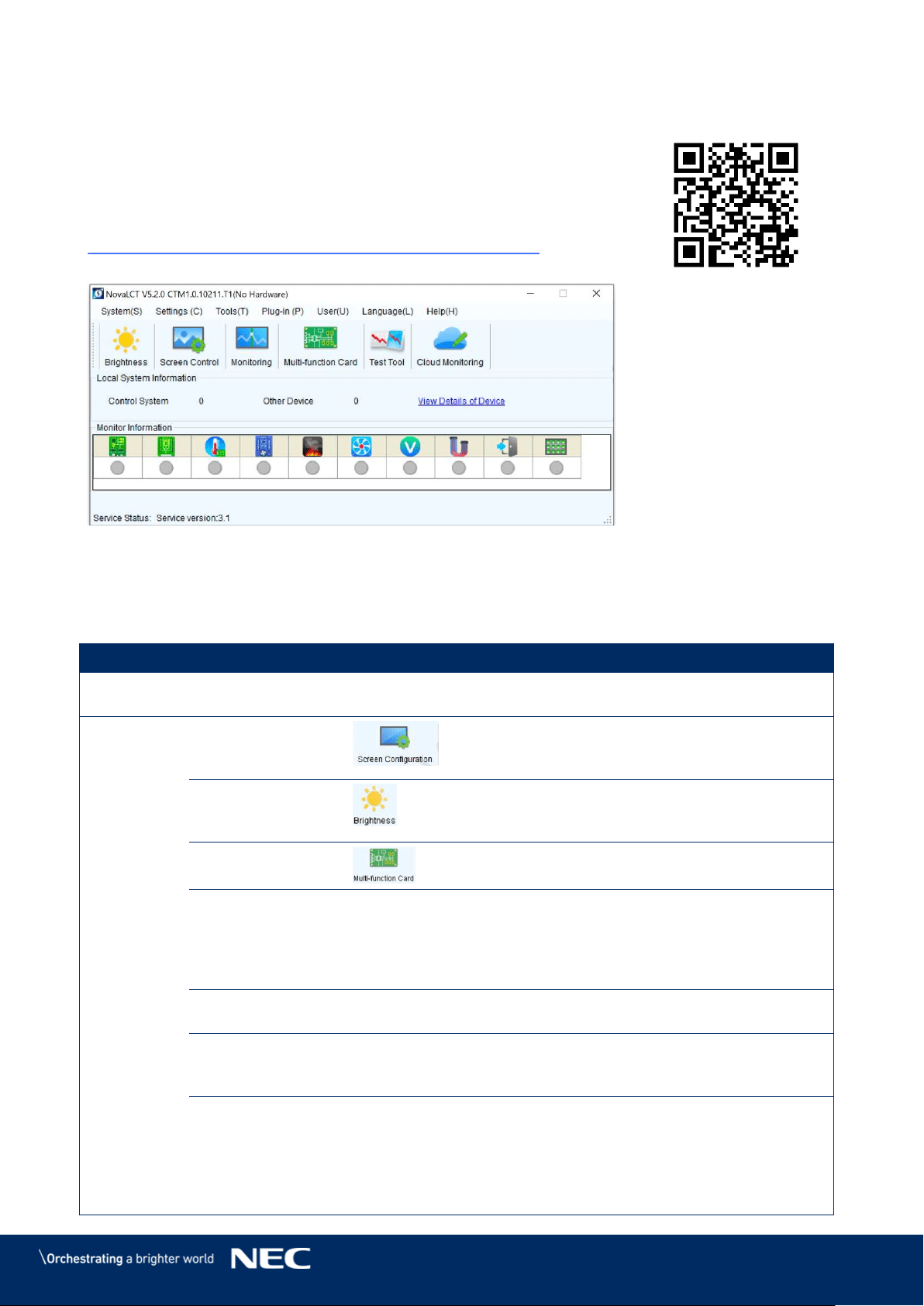
64
8
SOFTWARE NOVALCT
Control, configuration and calibration of the LED Wall is managed by
NovaLCT Software.
For detailed information, see the respective manual for NovaLCT Software.
Download the current version at:
https://www.novastar.tech/download/download-software/
Figure 87: Start Screen Software NovaLCT
8.1
Function Overview
Table 13: Main Menus and Functions
Menu
Description
System
Reconnect
Reconnect the NovaLCT to the synchronous
system.
Settings
Screen
Configuration
(Advanced User)
Configure the LED screens.
Brightness
Adjust the brightness of the LED display. There
are two ways for brightness adjustment,
automatic brightness and manual brightness.
Multi-function
Card
Open the page for Multi-function card
configuration.
Multiple-screen
Management
Open the page for combined display
configuration. The management of brightness
control and monitoring of multiple LED displays
is easier when these LED displays are combined
together.
Hardware
Information
Check the information on the current control
system for the LED display.
Restore Screen
Configure the settings for the restore screen,
booting screen and no signal screen (including a
disconnected network cable and no DVI signal).
Advanced Color
Configuration
(Advanced User)
Allows to configure the settings for:
Color temperature table
Factory setting (current gain, RGB
brightness).
Configuration color space (original color
space, target color space).
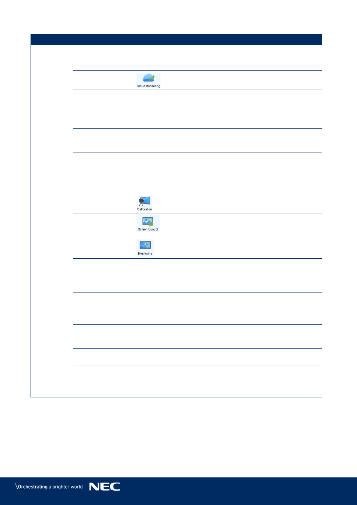
65
Menu
Description
Adjust Screen
Effect
(Advanced User)
Enable/Disable 18-bit mode and ClearView
mode.
Cloud Monitoring
Register the display screen to NovaCare.
Module Flash
View correction coefficients of the Receiving
card and module.
Save correction coefficients in the Receiving
card and module.
Test whether Flash is normal.
Receiving Card
Relay
(Advanced User)
Set parameters for the Receiving card relay.
Reset the time of the Receiving card.
Configure
Information
Management
Import/Export all the configuration files.
The Main Window
Starting Position
Set the initial coordinates.
Tools
Calibration
Calibrate the screen and manage the calibration
coefficients.
Screen Control
Perform the screen control functions which
include "Black Out", "Freeze" and "Normal".
Besides, self-test options are also provided.
Monitoring
View the monitoring results or set the
monitoring parameters.
LED Error
Detection
Detect LED errors after the screen has been
properly configured.
Multi-batch
Adjustment
Adjust the brightness of the display according
to the batches of cabinet.
Controller
Cabinet
Configuration File
Import
Add/Delete configuration files.
Modify file name.
Save the configuration file in hardware.
Quickly Adjust
Dark or Bright
Lines
Adjust or restore dark or bright lines caused by
cabinet splicing.
Video Control
Adjust the input setting, output setting and
stitching management of the video processor.
Module ID Setting
(Advanced User)
Perform module ID configuration to make
module management easier. Some modules do
not support ID configuration, please contact
NovaStar's technicians for details.
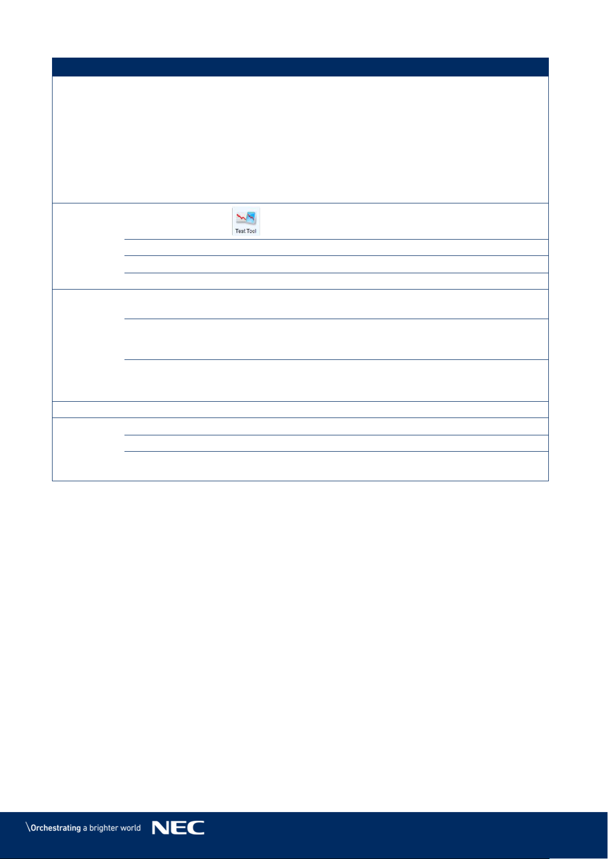
66
Menu
Description
More
Includes "Reset Run Time", "Brighter Pixel
Correction" and "Bite Error Detection".
"Reset Run Time": Reset the run time
displayed on the LCD of each cabinet.
"Brighter Pixel Correction": Correct the
brightness so the calibrated screen is equally
bright.
"Bite Error Detection": Detect the data packet
loss during communication between
Receiving cards.
Plugins
Test Tool
Open all test tools (test content) for LED
displays testing.
Calculator
Open the Microsoft Windows calculator.
External Program
Add an external program.
DHCP Service
Obtain the IP address assigned by the server.
User
Advanced User
Login
Log in the synchronous system with the
password "admin".
Enter
Demonstration
mode
Experience the related functions of the
synchronous system. No hardware connection
is required. Use the password "admin".
Connect
Asynchronous
Terminal
Log in the multimedia player.
Language
-
Support multiple user interface languages.
Help
User Documents
View software-related user documents.
Update log
View software update logs.
About
View software version, company name and
other information.
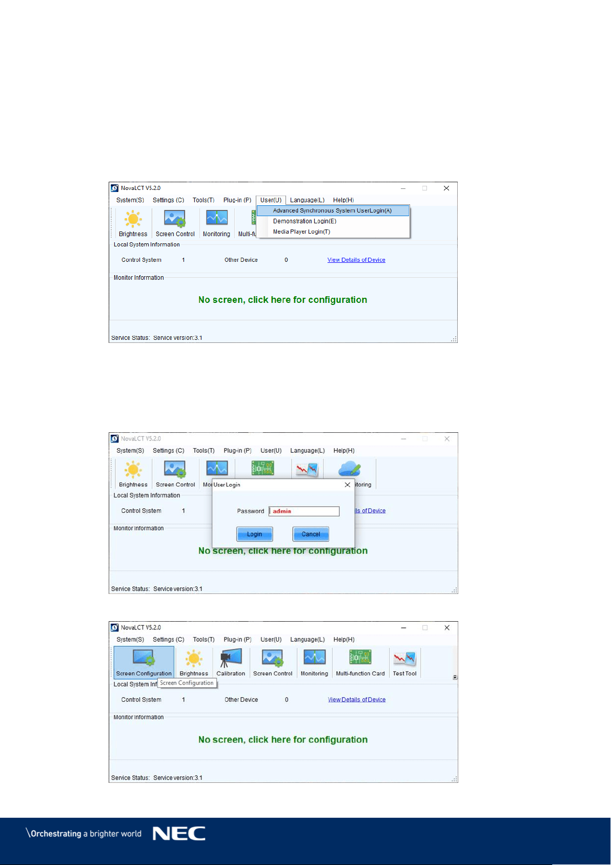
67
8.2
Advanced User Login
Asynchronous users need to log in to NovaLCT as Advanced Users to configure screens as
required.
Start the software NovaLCT. Step 1)
Click the User(U) menu and select Advanced Synchronous System User Login(A) Step 2)
(see Figure 88).
Figure 88: Advanced User Login
Enter the password into the Password field. The default password is admin. Step 3)
Click the Login button to confirm the entry (see Figure 89). Step 4)
If the Login is successful, the interface below will appear (see Figure 90).
The start screen refreshes automatically.
Figure 89: Entering Password
Figure 90: Interface after successful Login
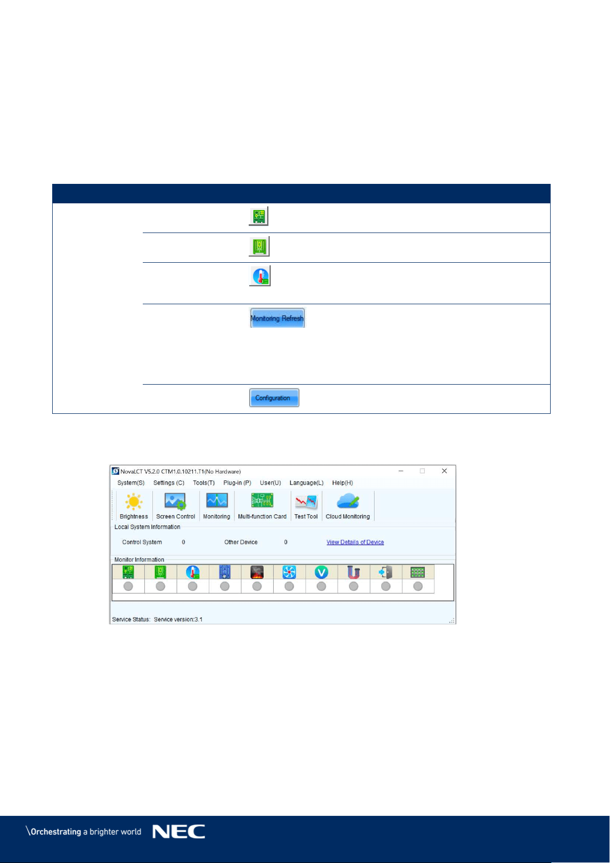
68
8.3
Monitoring
NovaLCT supports monitoring the status of Sending cards (NovaStar Controller), Receiving cards
and Monitoring cards, as well as temperature, humidity, smoke, fan, power supply, ribbon cable,
cabinet door and smart module. NovaLCT is applicable to both ordinary screen and combined
screen.
Function Overview 8.3.1
Table 14: Monitoring – Main Functions
Menu
Description
Start screen
Sending Card
Check the connection of the Sending cards.
Receiving Card
Check the wiring of the Receiving card and
the Power supplies.
Temperature
Check the temperature of each module and
the Operating status of each individual
Power supply solution.
Monitoring
Refresh
Update the monitored data.
Modify refresh period and re-read times
when reading the status "failed" at the
refresh period interface, where in the period
is the period of refreshing the monitoring
data.
Configuration
Edit the contents to be monitored and set
rules for alarm.
Start Monitoring Function 8.3.2
Click the Monitoring button to open the monitoring interface (see Figure 91). Step 1)
Figure 91: Starting the Monitoring function
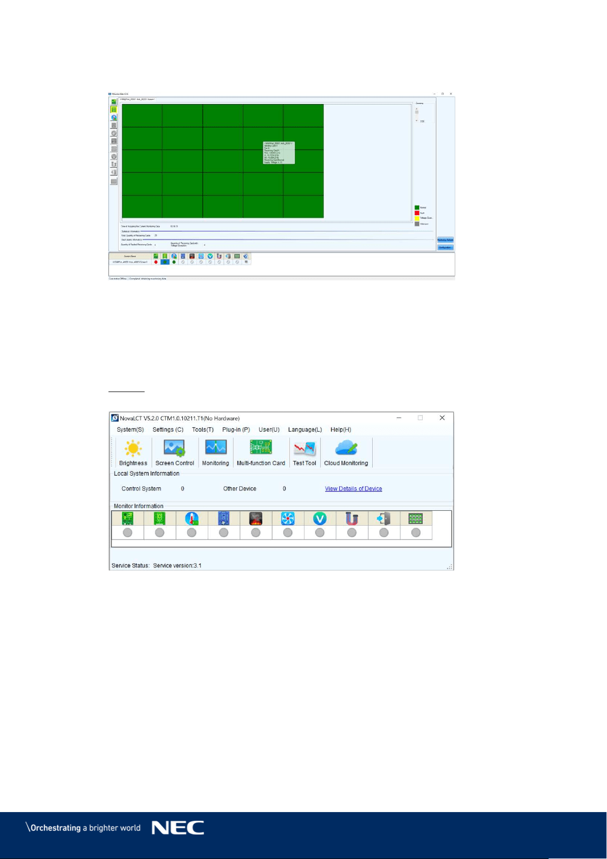
69
The Monitoring interface will open. By default, the Monitoring view for the Receiving Step 1)
cards is opened (see Figure 92).
Figure 92: Start Screen Monitoring
Receiving Card and Power supplies 8.3.3
The Monitoring view of the Receiving card and the Power supplies offers checking the wiring.
Errors will be shown in colored surfaces. The color codes are defined in the interface itself.
Click the Monitoring button to open the monitoring interface (see Figure 93). Step 1)
Result: The Monitoring interface will open. By default, the Monitoring view for the
Receiving cards is opened (see Figure 94).
Figure 93: Starting the Monitoring Function
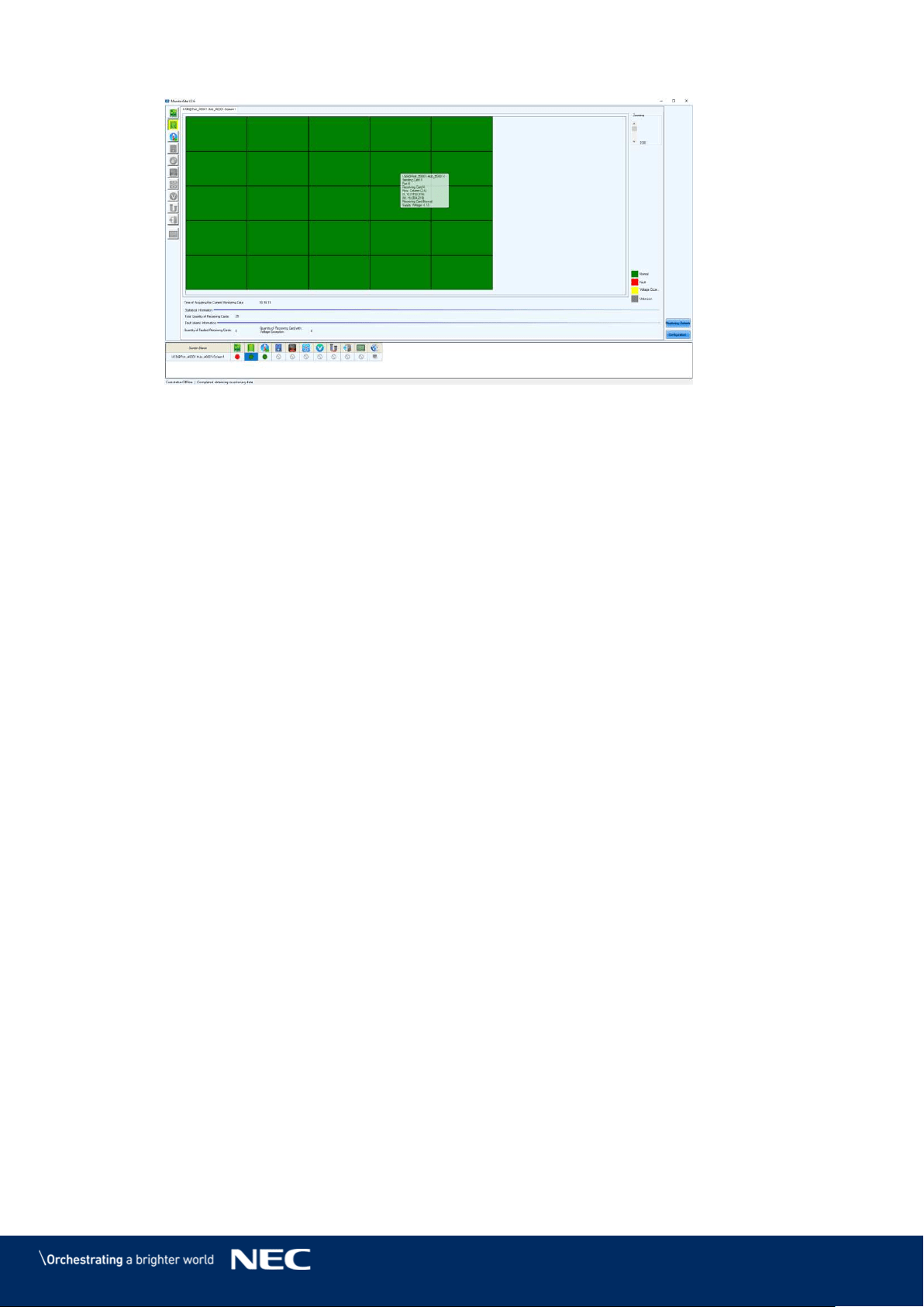
70
Figure 94: Start Screen Monitoring Receiving Cards and Power Supplies
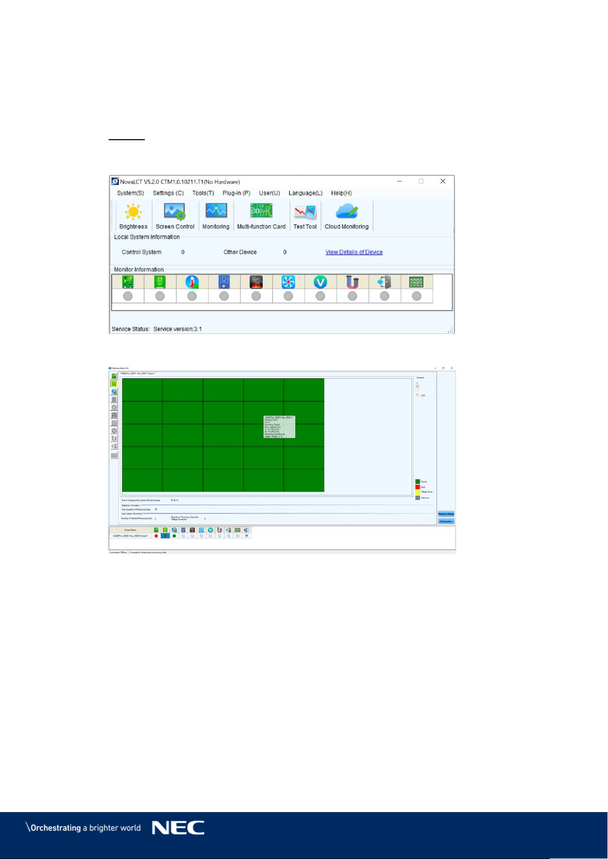
71
Sending Card 8.3.4
The Monitoring view of the Sending card offers checking the connection of the Sending cards.
Errors will be shown in colored surfaces. The color codes are defined in the interface itself.
Click the Monitoring button to open the Monitoring interface (see Figure 95). Step 1)
Result: The Monitoring interface will open. By default, the Monitoring view for the
Receiving cards is opened (see Figure 96).
Figure 95: Starting the Monitoring Function
Figure 96: Start Screen Monitoring Receiving Cards and Power Supplies
Click Sending Card button to switch to the Monitoring view for the Sending card (see Step 2)
Figure 97).
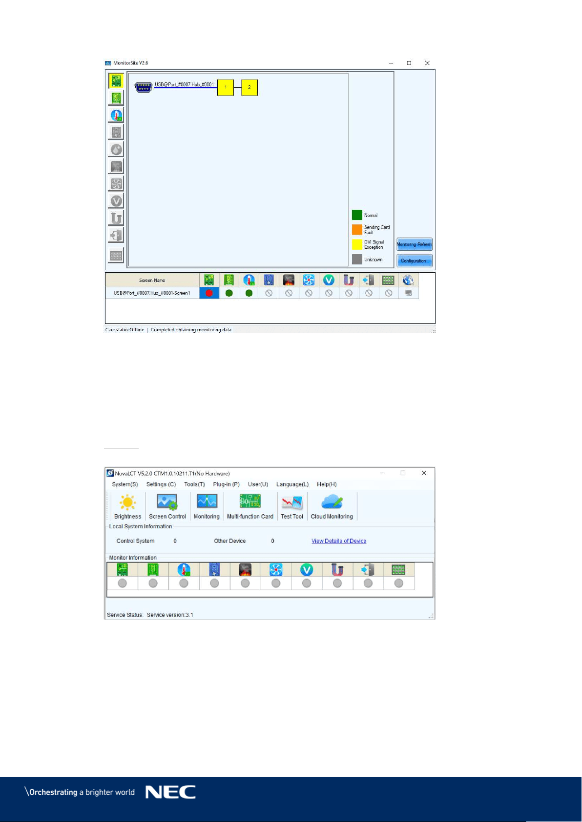
72
Figure 97: Start Screen Monitoring Sending Card
Temperature 8.3.5
The Monitoring view Temperature offers checking the temperature of each module and the
Operating status of each individual power supply solution. Errors will be shown in colored surfaces.
The color codes are defined in the interface itself.
Click the Monitoring button to open the monitoring interface (see Figure 98). Step 1)
Result: The Monitoring interface will open. By default, the Monitoring view for the
Receiving cards is opened (see Figure 99).
Figure 98: Starting the Monitoring Function
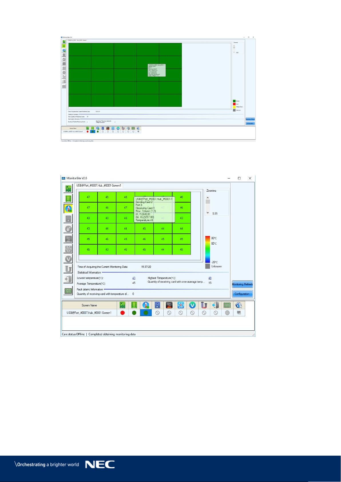
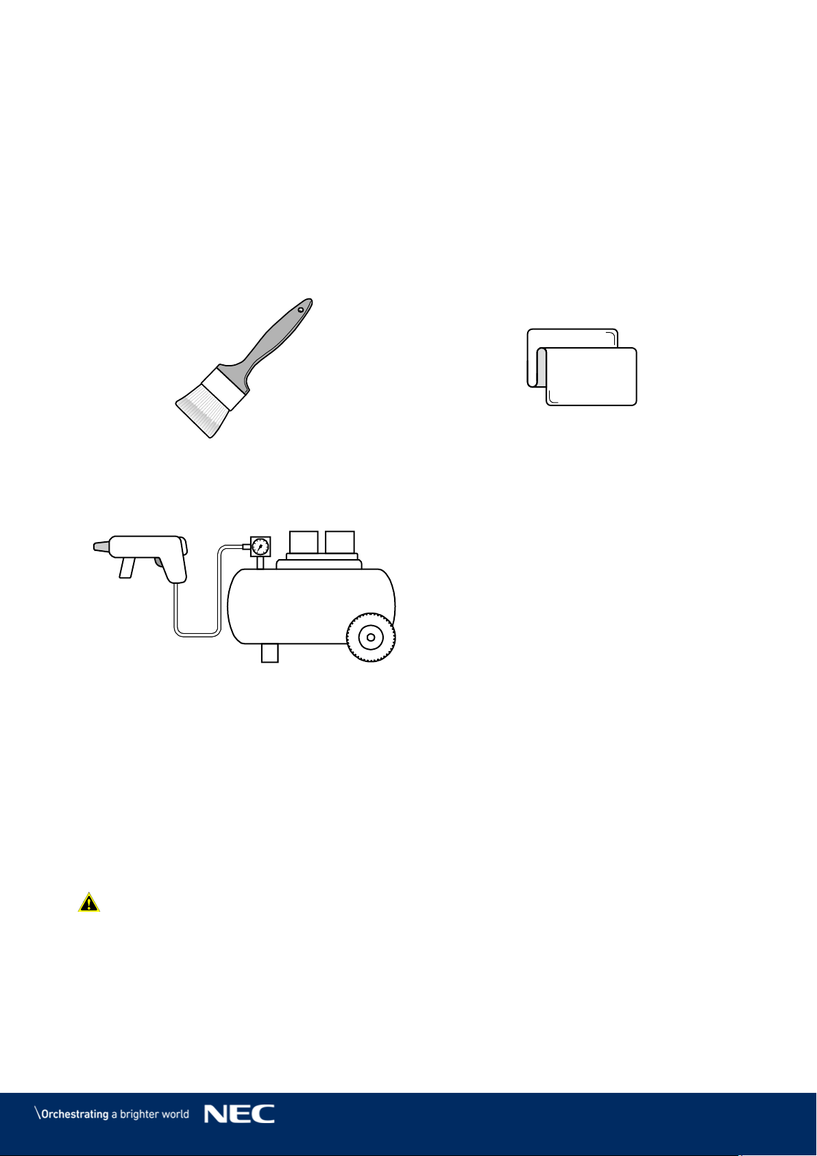
74
9
CLEANING
The screen brightness may decrease if dust or another foreign material is adhering to the surface
of the pixel card.
The magnet used to install the pixel cards also attracts magnetic metal particles, such as iron
powder.
Therefore, magnetic metal particles may adhere to areas near the magnet of the pixel card and
the brightness homogeneity of the screen may decrease.
Cleaning should be performed regularly depending on the installation environment.
Required tools (example)
Soft brush
(animal hair brush to prevent static electricity)
Soft cloth
(that does not generate static electricity)
Air blower (compressor)
1.
Cleaning method
Turn the LED displays off. a)
Use the soft brush to remove any dirt on the LED lamps and the masks. If these parts are b)
very dirty, use the air blower to remove the dirt.
Use the soft cloth to remove the dirt on the screen surface. c)
Repeat the steps (b) and (c) to remove all the dirt. d)
Caution!
- Do not use water or any other liquid.
- Do not use a stiff brush.
- Pay attention not to damage the LED lamps when using the soft brush, the air blower, or the
soft cloth.
75
10
MAINTENANCE
10.1
Routine Maintenance
Caution!
Risk of electric shock.
Always disconnect the FE Series LED Wall from the power outlet before
performing any maintenance work.
Regular use
After you put the LED Wall into use, use it 25–30 h and 5-times a month so the LED Wall stays dry
and delivers a stable performance.
Daily
Check the LED Wall visually for physical damages.
10.2
Regular Cleaning
Caution!
Risk of product damage by moisture or water.
Do not clean the system with water. Do not wipe the LED Pixel cards with a damp
cloth.
Notice
Clean the components of the LED Wall very carefully to avoid damaging the surfaces. Do not
alter the cleaning procedure, otherwise pixels or Pixel cards can be permanently damaged.
Under normal conditions the recommended cleaning interval of the LED display is every six
months.
Before cleaning:
Disconnect the LED Wall from mains power.
Lock electric power supply against re-closure.
If the cabinets are still warm from their latest usage, wait with cleaning until they are
completely cooled down.
Cleaning:
Use a dry, anti-static brush to sweep from right to left, means only horizontally.
Blow-dry only the front of the cabinets with compressed air and only from a large distance.
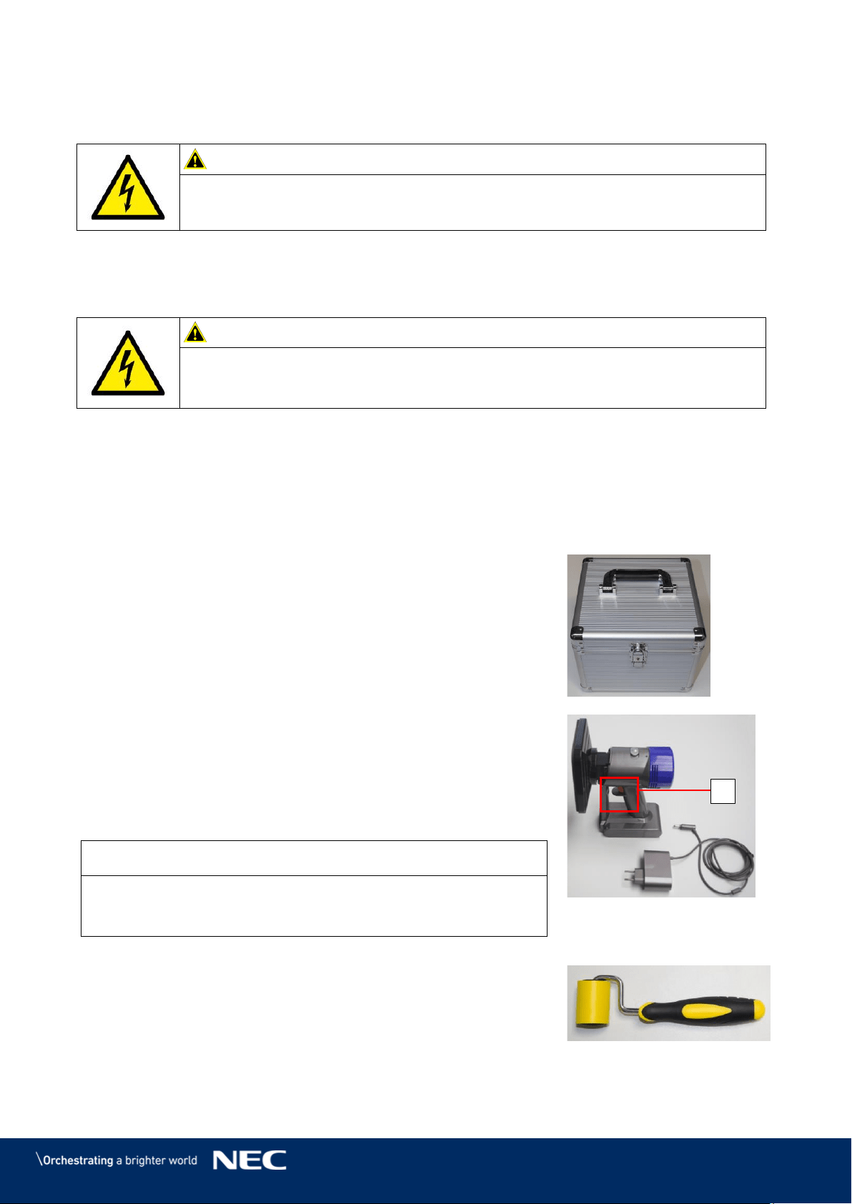
76
10.3
Power System Maintenance
Caution!
Risk of electric shock.
Do not use the LED Video Display if you detect any faults in the power supply.
Daily
Check all cables visually for physical damages.
Every six months
Caution!
Risk of electric shock.
Only qualified personnel with an electrician certificate are allowed to perform
maintenance work.
Clean the interior of the power distribution cabinet and fasten screw connections.
10.4
Maintenance Tools
To guarantee a smooth and easy maintenance, use the following special tools provided in the
delivery package:
Pixel Card Service Tool with Charger:
Use the Service tool to remove the Pixel cards in a safe and easy
way.
The Service tool comes with a battery and charger for wireless
usage.
Ensure the Service tool is charged properly before using it.
Usage:
Set the air pressure regulator on the Service tool to Max.
Push the Service tool on a Pixel card and hold the red button (A).
The Service tool creates a vacuum that will suck out the Pixel
card.
When it holds the Pixel Card, pull the Service tool horizontally
from the LED wall towards you.
Notice
Always put one hand below the removed Pixel card to prevent it
from falling down in case the Service tool's battery dies or it
releases the Pixel card too early.
Figure 101: Pixel Card
Service Tool
Mask Roller:
This roller is used to smooth the edges of the masks on the display.
Figure 102: Mask Roller
A
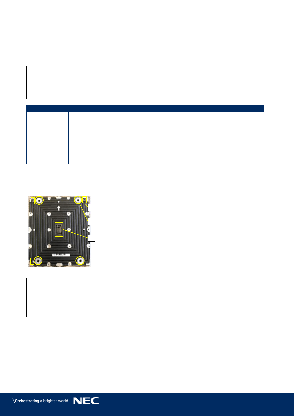
77
10.5
Front Service
The following instruction will guide through the exchange of all replaceable parts.
All replacements require the removal of the Pixel cards first. Replacement of power supply and
Receiving cards require additionally the removal of the hub board.
Notice
It is essential to wear a glove at least at the hand that might touch the front of the LED cabinet,
because the LEDs are very sensitive to the greasy film on the skin, and ensure ESD protection.
Ensure the Service tool is charged properly before using it.
No. of People
2
Prerequisites
LED Wall is disconnected from mains power
Tools
Screwdriver PH1
Service tool
White ESD gloves
Foam packing material and anti-static plastic bag for the Pixel cards
Heat conducting paste (for servicing the power supply)
Change the Pixel Cards 10.5.1
The Front service takes only 10 seconds to exchange a pixel module. This convenience is due to
the unique magnet interfaces (A), corner click-pins (B) and Pixel card connector (C).
Figure 103: Pixel Card
Notice
During the removal process, put your free hand below the Pixel card removal position, ready to
catch it.
By this, you can prevent the Pixel card from falling down in case the tool's battery dies or it
releases the Pixel card too early.
Set the air pressure regulator on the Service tool to Max. Step 1)
Place Service tool centered on the Pixel card. Step 2)
Push the Service tool on a Pixel card and keep the red button pressed so the Service Step 3)
tool holds the Pixel card firmly.
Carefully pull the Service tool with the Pixel card horizontally and steady out of the LED Step 4)
Wall.
A
B
C
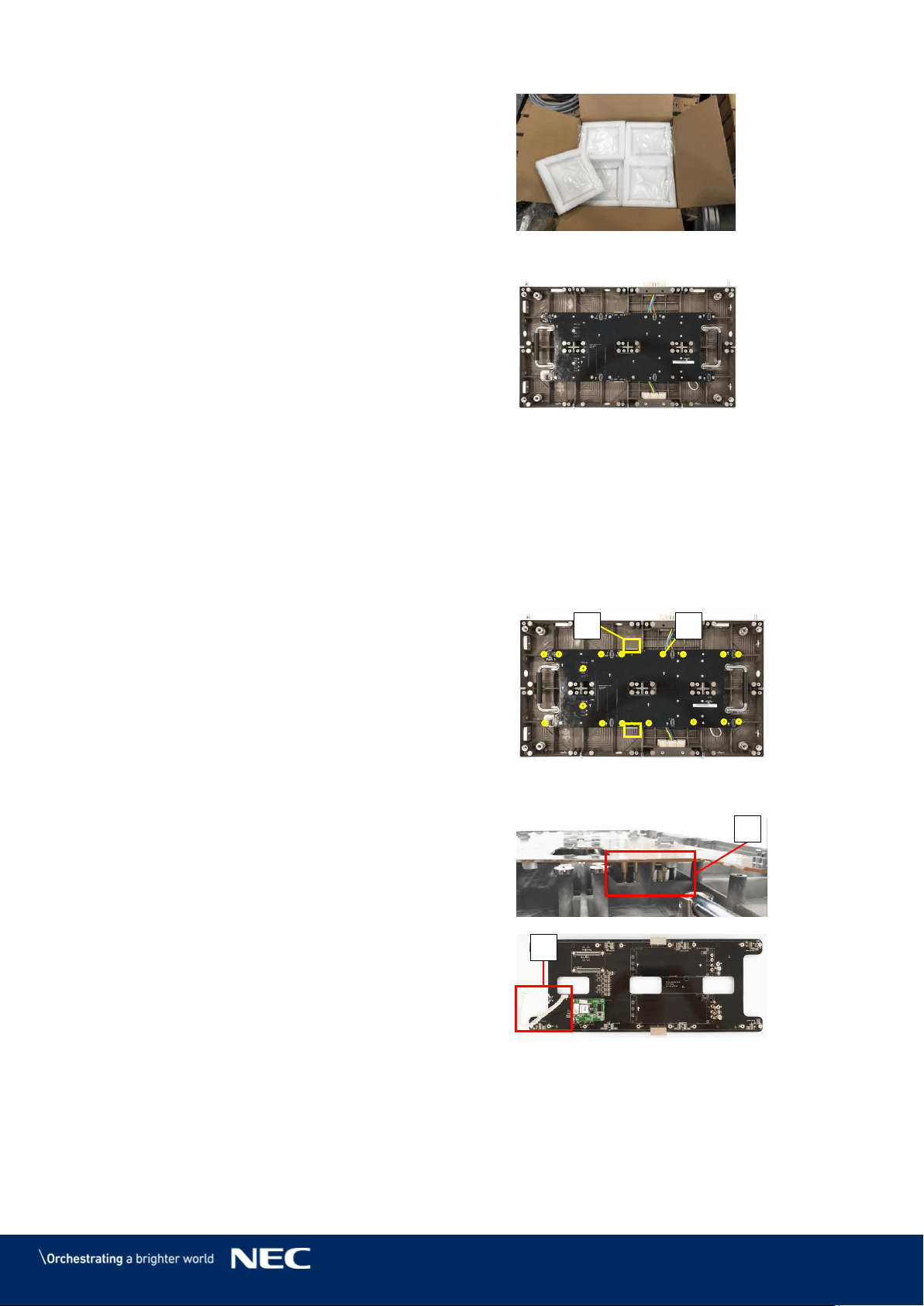
78
Put the removed Pixel card into its foam
Step 5)
form.
Figure 104: Foam Forms for Pixel Cards
After removing all Pixel cards, the cabinet looks like
shown in Figure 105.
Install new Pixel cards
Take the Pixel cards out of the spare part
Step 6)
package.
Place the Pixel card carefully by hand or
Step 7)
Service Tool to the screen.
Load the calibration data on the new Pixel
Step 8)
card (see 7.4 Update the Calibration Data
after Installing All Pixel Cards).
Figure 105: Cabinet without Pixel Cards
Remove the Hub Board 10.5.2
For servicing the Hub board, you need to remove the Pixel cards first (see 10.5.1).
Disconnect the Ethernet connections (A)
Step 1)
from the Hub board.
Remove the 16 screws (B), which connect
Step 2)
the Hub board to the cabinet.
Figure 106: Screws on Hub Board
Pull the Hub board straight off the cabinet.
Step 3)
Be careful not to damage the Power supply
interface (C) on the Hub board and the PSU.
Disconnect the Signal light cable (D) from
Step 4)
the cabinet.
Now you can access the power supply in the
Step 5)
cabinet and the Receiving card on the Hub
board.
Re-install the Hub board in reverse order.
Step 6)
Take great care not to bent any connectors.
Figure 107: Removal of Hub Board
A
B
C
D
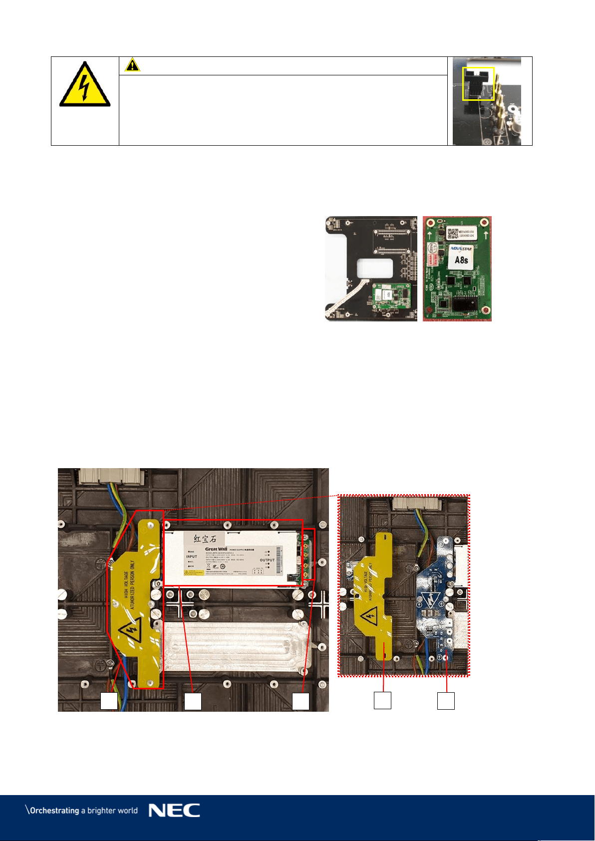
79
Caution!
Risk of damaging the Hub board.
When reinstalling the Hub board, do not bent the two
Power-good-connectors.
With bent connectors, the whole module cannot work properly.
Change the Receiving Card
10.5.3
For servicing the Receiving card, you first need to remove the Pixel cards (see 10.5.1) and the
Hub board (see 10.5.2).
Pull the Receiving card straight off the Hub
Step 1)
board. Be careful not to damage their
connectors.
Replace the Receiving card.
Step 2)
To replace the Receiving card, follow the
Step 3)
instructions in reverse order.
Figure 108: Replacing the Receiving Card
Change the Power Supply System
10.5.4
For servicing the power supply, you first need to remove the Pixel cards (see 10.5.1) and the Hub
board (see 10.5.2). Now the power supply in the cabinet is accessible.
The following components contribute to the power supply of a module:
1 Power supply unit (PSU) (A)
1 Power distribution unit (PDU) (B1) with PDU shielding (B2)
1 Power supply interfaces to Hub board (C)
Figure 109: Behind Hub Board –Power Supply and PDU with PDU Shielding
B
B2
B1
A
C
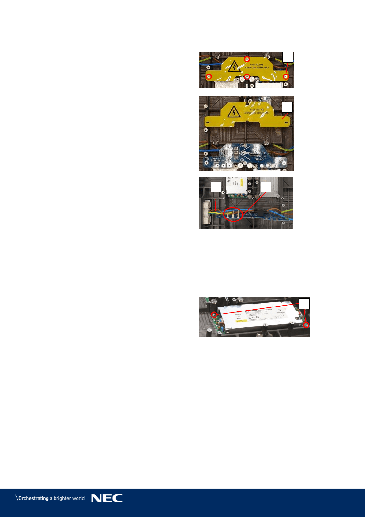
80
Replace the Power Distribution Unit
Loosen the four screws (D).
Step 1)
Remove the PDU shielding (B2).
Step 2)
Pull the PDU straight and carefully. Be
Step 3)
careful not to damage the connectors to
the PSU or the wiring (E).
Disconnect the cables from the PDU's
Step 4)
terminal (F).
Figure 110: Removing Shielding & PDU
Replace the PDU.
Step 5)
To reinstall the replaced PDU, follow the steps in reverse order.
Step 6)
Replace the Power Supply Unit
To replace the PSU, remove the Power distribution unit (PDU) first. See above for instructions.
Remove the two screws (G).
Step 1)
Take the PSU carefully off.
Step 2)
Place the PSU upside down so the heat-conducting paste shows upwards and no other
Step 3)
parts become dirty from it.
Before replacing the PSU, distribute some heat-conducting paste on the bottom.
Step 4)
Carefully place the new PSU in its dedicated spot.
Step 5)
Screw in the two screws (G).
Step 6)
D
B2
E
F
G
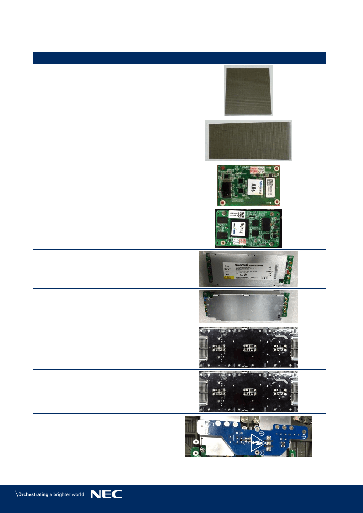
81
11
SPARE PARTS
Part Name
Pixel Card
Pixel Card (For 2.5 mm only)
Receiving card A8S
Receiving card A10S Plus(For 0.9 mm only)
Power supply
Power supply (For 0.9 mm only)
Data hub
Data hub (For 0.9 mm only)
AC terminal Hub
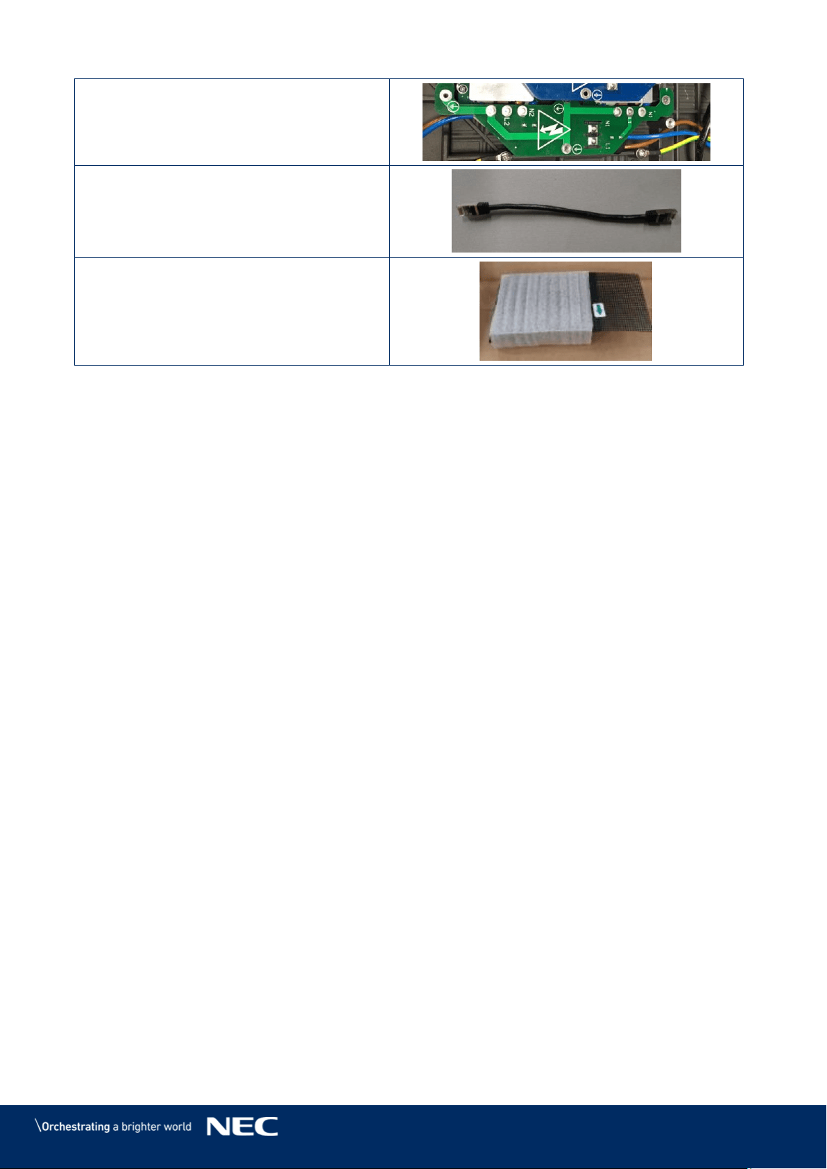
82
AC terminal Hub (For 0.9 mm only)
CAT cable
Mask (For 1.5/1.9/2.5/3.8 mm only)
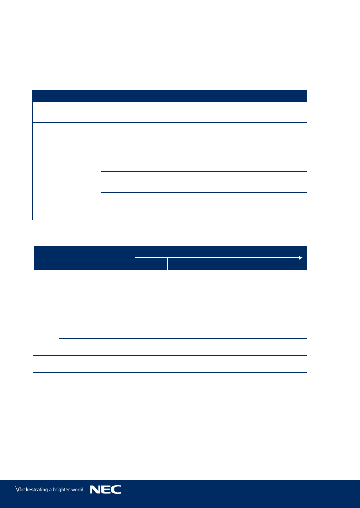
83
12
TROUBLESHOOTING
Table 15 summarizes the most common problems you could encounter with the appliance.
If you are unable to solve the problem with the information below, contact the NEC DISPLAY
SOLUTIONS service team: LED-support@nec-displays.com
Table 15: Troubleshooting Solutions
Problem
Solution
No power
Check if electric power is switched on.
Check if screen is connected properly to the electric power system.
No picture
Adjust the contrast and brightness settings.
Check if the screen saver is activated.
No signal input
Check the green LED of the Receiving card is flickering regularly or
not (fast flickering means no signal).
1. Check if the cable connector assembly is stable.
2. Check whether the cable is short-circuited.
3. Check the power of the Receiving card.
In case the above three points do not fix the problem, please
exchange the Receiving card.
Module not working
Use a multimeter to test the module. The voltage should be 4.2 V.
Table 16: Signal Light Codes
Light
Meaning
Signal Interval [in sec]
1
2
3
4
5
6
7
8
9
green
Power supply on
Power supply off
red
Data connection ok
Data connection bad
[1 ms]
[1 ms]
[1 ms]
Signal on Controller
lost
blue
not relevant
84
13
DISPOSAL
13.1
Within the European Union
WEEE Mark (European Directive 2012/19/EU and amendments)
Disposing of your used product: In the European Union
EU-wide legislation as implemented in each Member State requires that
used electrical and electronic products carrying the mark (see on the left)
must be disposed of separately from normal household waste. This
includes monitors and electrical accessories, such as signal cables or
power cords. When you dispose of such products, please follow the
guidance of your local authority or ask the shop where you purchased the
product, or if applicable, follow applicable legislation or agreement you
may have. The mark on electrical and electronic products my only apply
to the current European Member States.
13.2
Outside the European Union
If you wish to dispose of used electrical and electronic products outside the European Union,
please contact your local authority and ask for the correct method of disposal.

85
14
COPYRIGHT AND DISCLAIMER
14.1
Copyright
This document is © Sharp NEC DISPLAY SOLUTIONS, all rights reserved.
NEC is a registered trademark of NEC Corporation.
All product and company names are property of their respective owners. Use of them does not
imply any affiliation with or endorsement by them.
NovaStar and NovaLCT is a registered trademark of NovaStar Tech Co., Ltd.
The terms HDMI and HDMI High-Definition Multimedia Interface, and the HDMI Logo are
trademarks or registered trademarks of HDMI Licensing Administrator, Inc. in the United States
and other countries.
14.2
Disclaimer
All instructions and specifications in this manual are based on information available at the time of
publishing for the features and safety guidelines of the described products.
Technical specifications, measurements, weights and properties are not guaranteed.
The manufacturer reserves the right to make product alterations within legal provisions as well as
changes to improve product quality.
Sharp NEC DISPLAY SOLUTIONS shall not be liable for personal injury or damage to materials
caused by failure to observe this warning and safety information of this manual. Furthermore,
Sharp NEC DISPLAY SOLUTIONS cannot be held responsible for damage or injury, caused by
incorrect, inadequate or unsafe use, maintenance or installation of the entire system. The liability
as well as the effects of the same will become void if other than genuine parts are used.
LOCAL REGULATIONS
This product and assembly variants that are shown in these instructions for assembly
and use may be subject to local regulations, guidelines and norms.
The product use bears the responsibility for compliance to and with such regulations.
Subject to local regulations, we reserve the right not to supply all products
illustrated here.
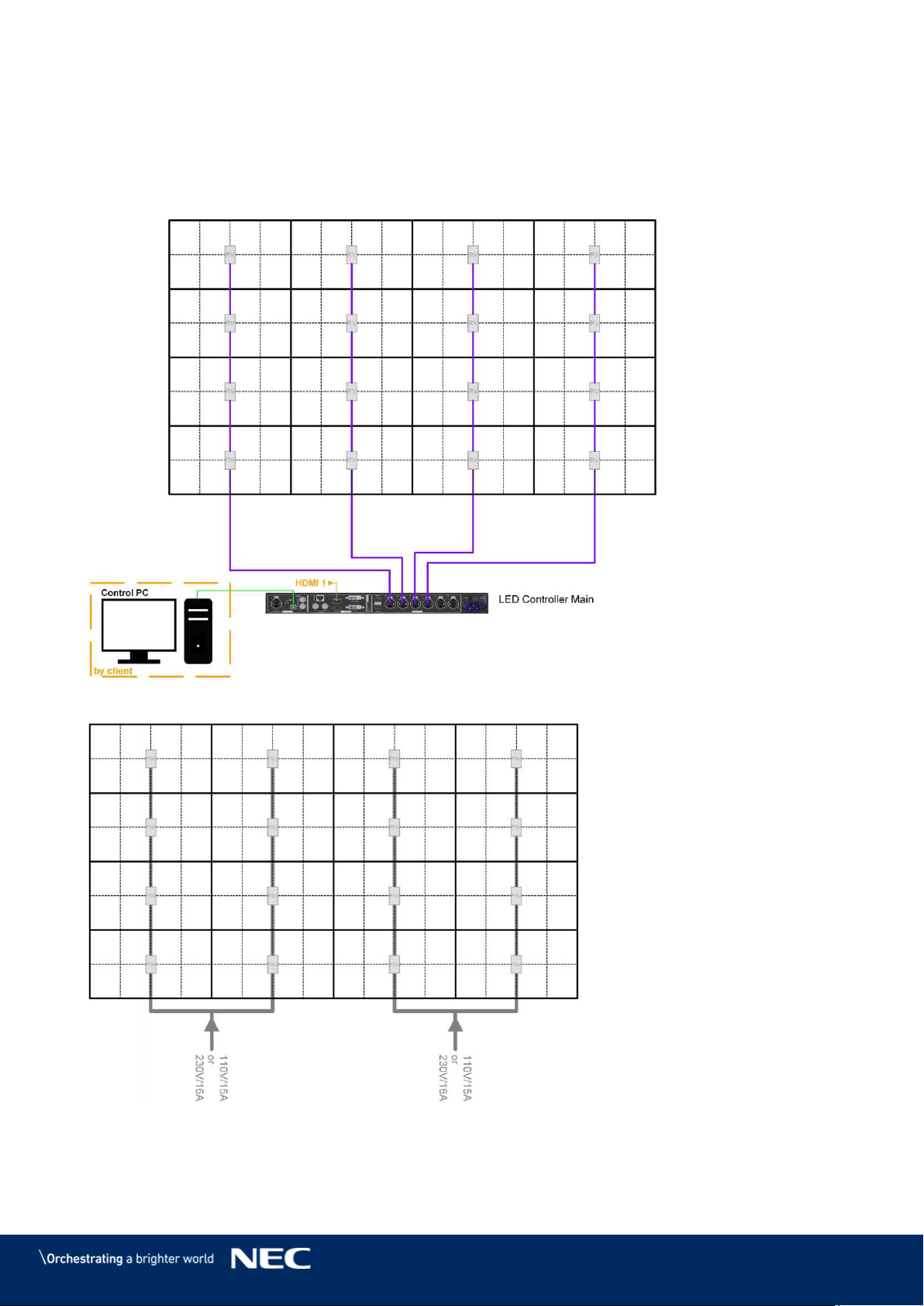
86
15
APPENDIX
15.1
Cable Plans
LED-FE012i2-110, LED-FE019i2-110: Data Connections 15.1.1
LED-FE012i2-110, LED-FE019i2-110: Power Connections 15.1.2
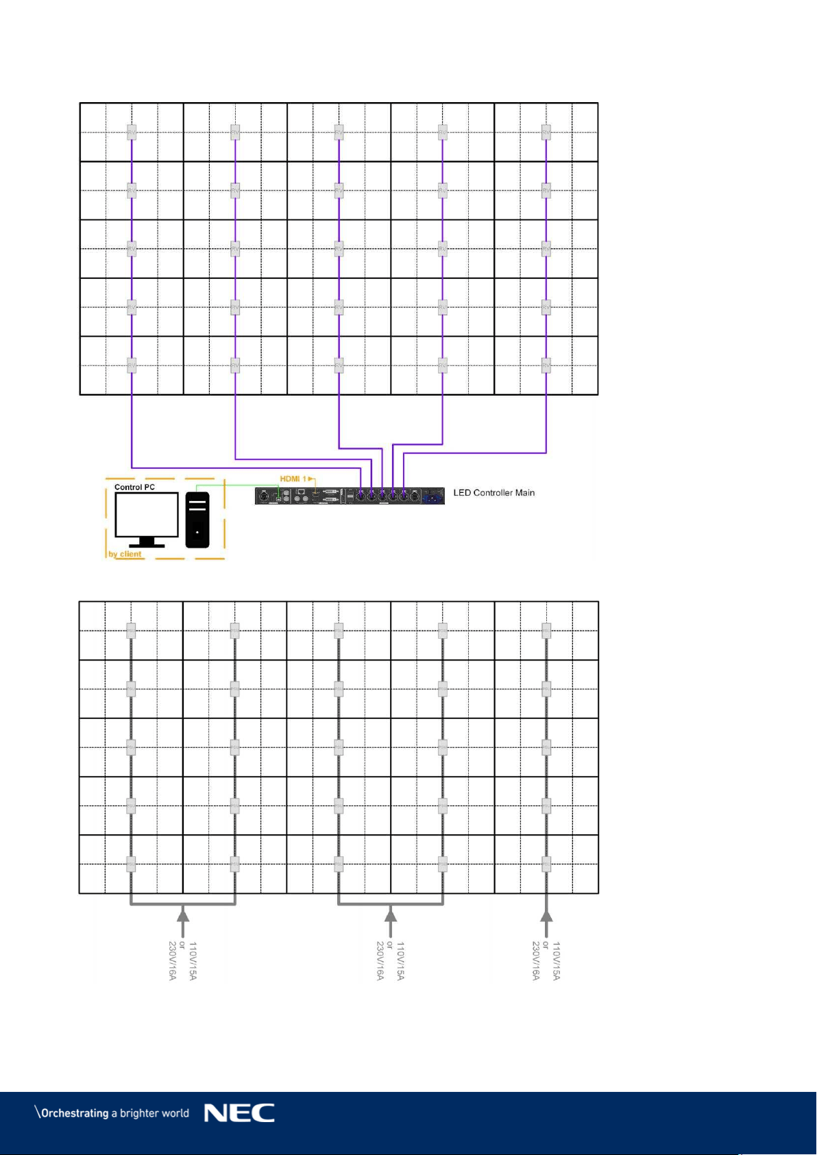
87
LED-FE015i2-137: Data Connections 15.1.3
LED-FE015i2-137: Power Connections 15.1.4
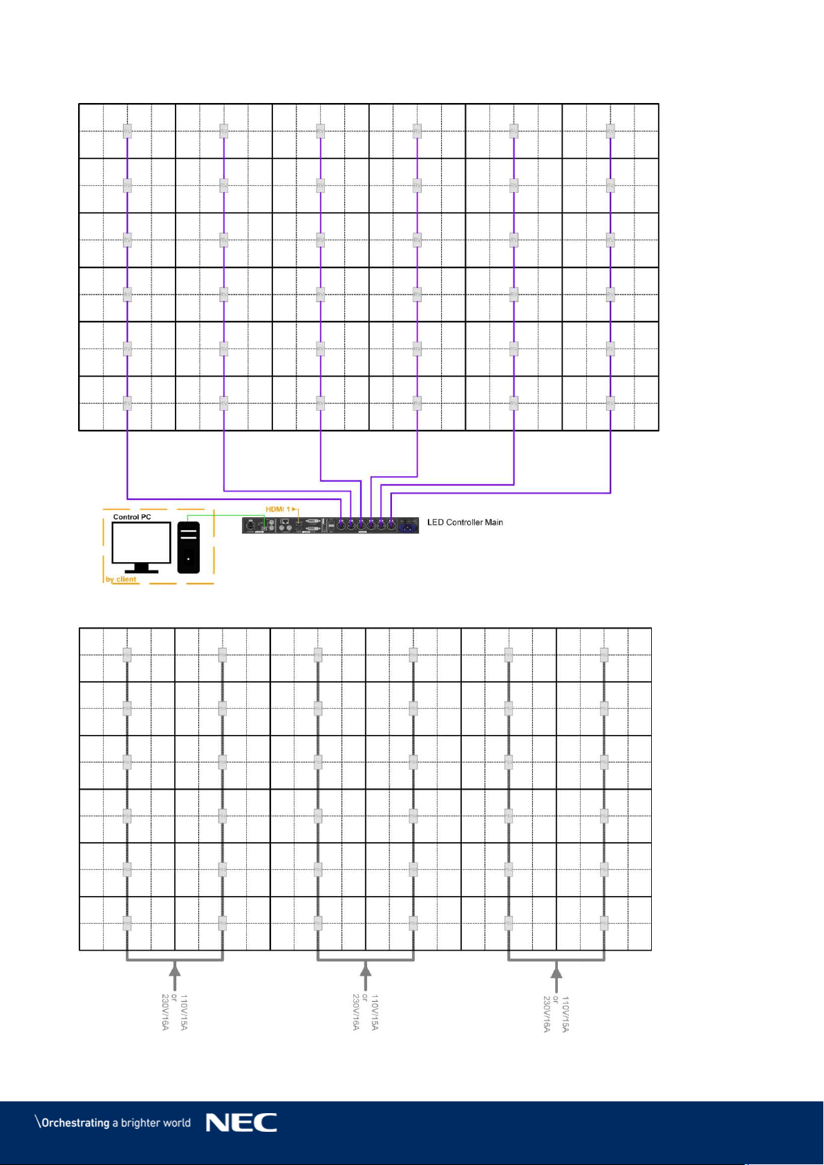
88
LED-FE019i2-165: Data Connections 15.1.5
LED-FE019i2-165: Power Connections 15.1.6
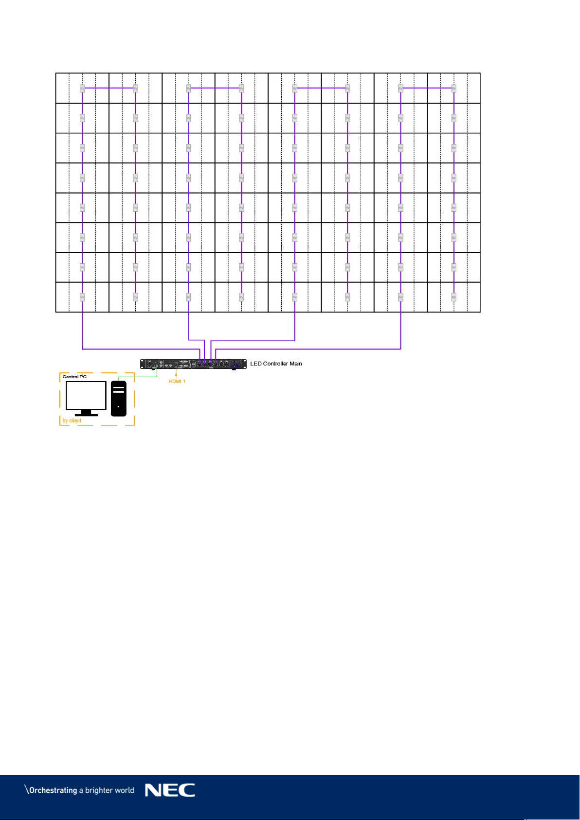
89
LED-FE025i2-220, LED-FE038i2-220: Data Connections 15.1.7
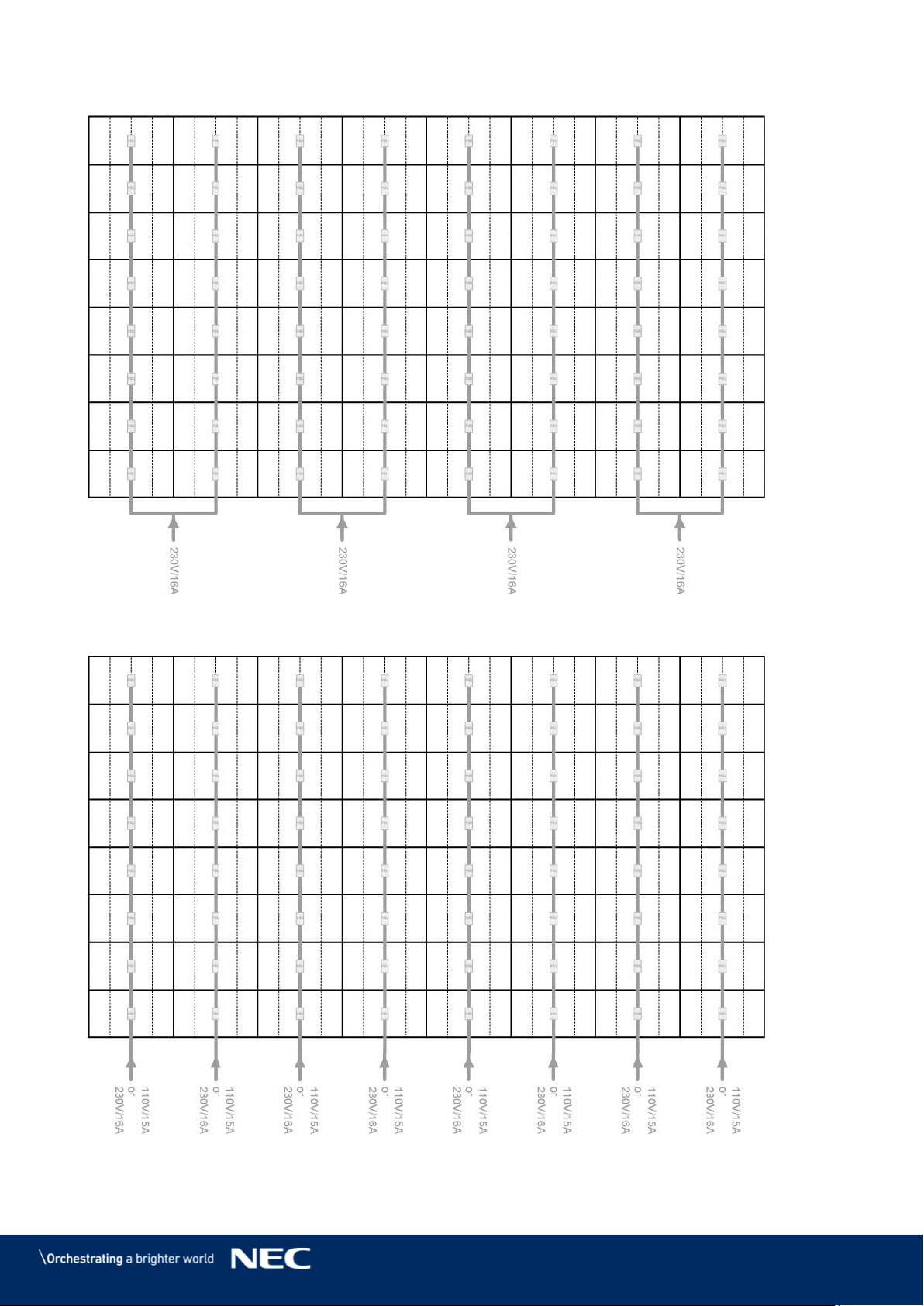
90
LED-FE025i2-220, LED-FE038i2-220: Power Connections 15.1.8
LED-FE025i2-220, LED-FE038i2-220: Power Connections 15.1.9
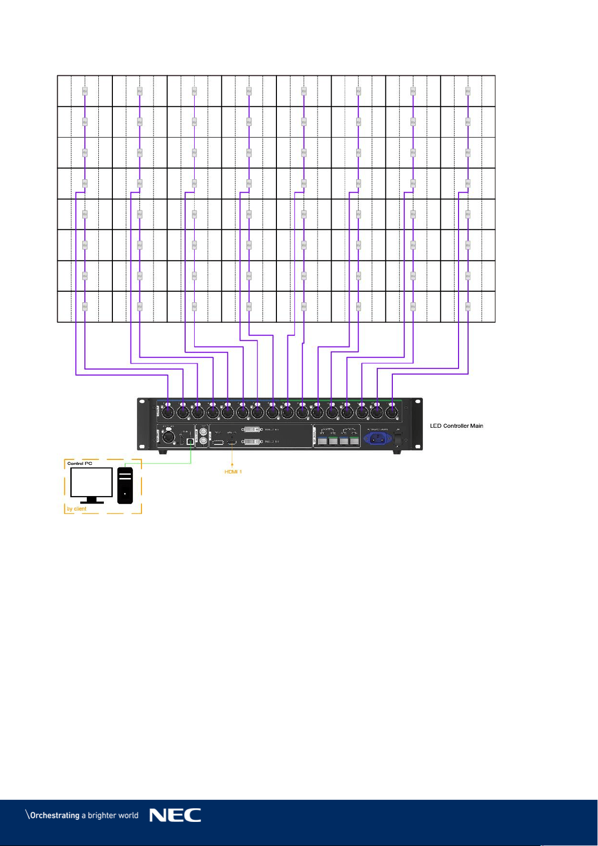
91
LED-FE012i2-220: Data Connections 15.1.10
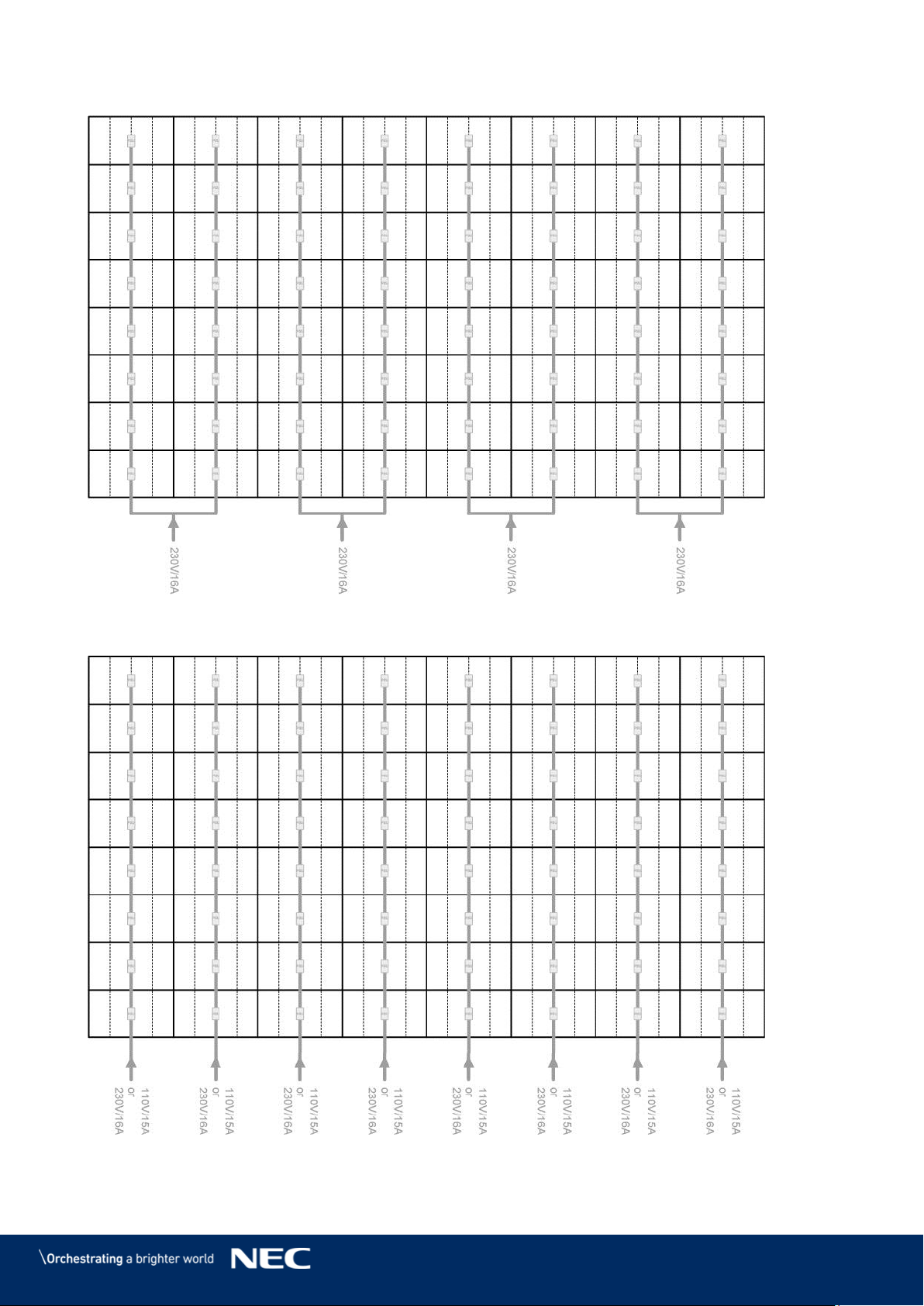
92
LED-FE012i2-220: Power Connections 15.1.11
LED-FE012i2-220: Power Connections 15.1.12
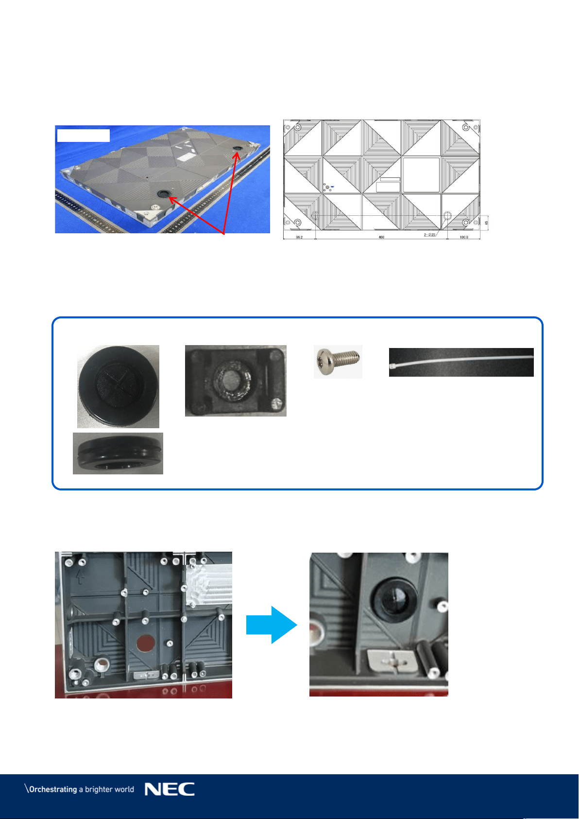
93
15.2
Backside hole cabinet
LED-FA-FE series can choose “backside hole cabinet”
Backside hole cabinet
Connect Power cable & LAN cable to use the following components.
Option parts : LED-FAFE2-BHCK
Connection method
Attach the feed sleeve to the cabinet. Step 1)
Backside hole
Back view
* Backside hole size : Φ25 mm
Cable feed sleeve
Cable fastening buckle
Screw(M3 x 8)
Cable fastening tie lap
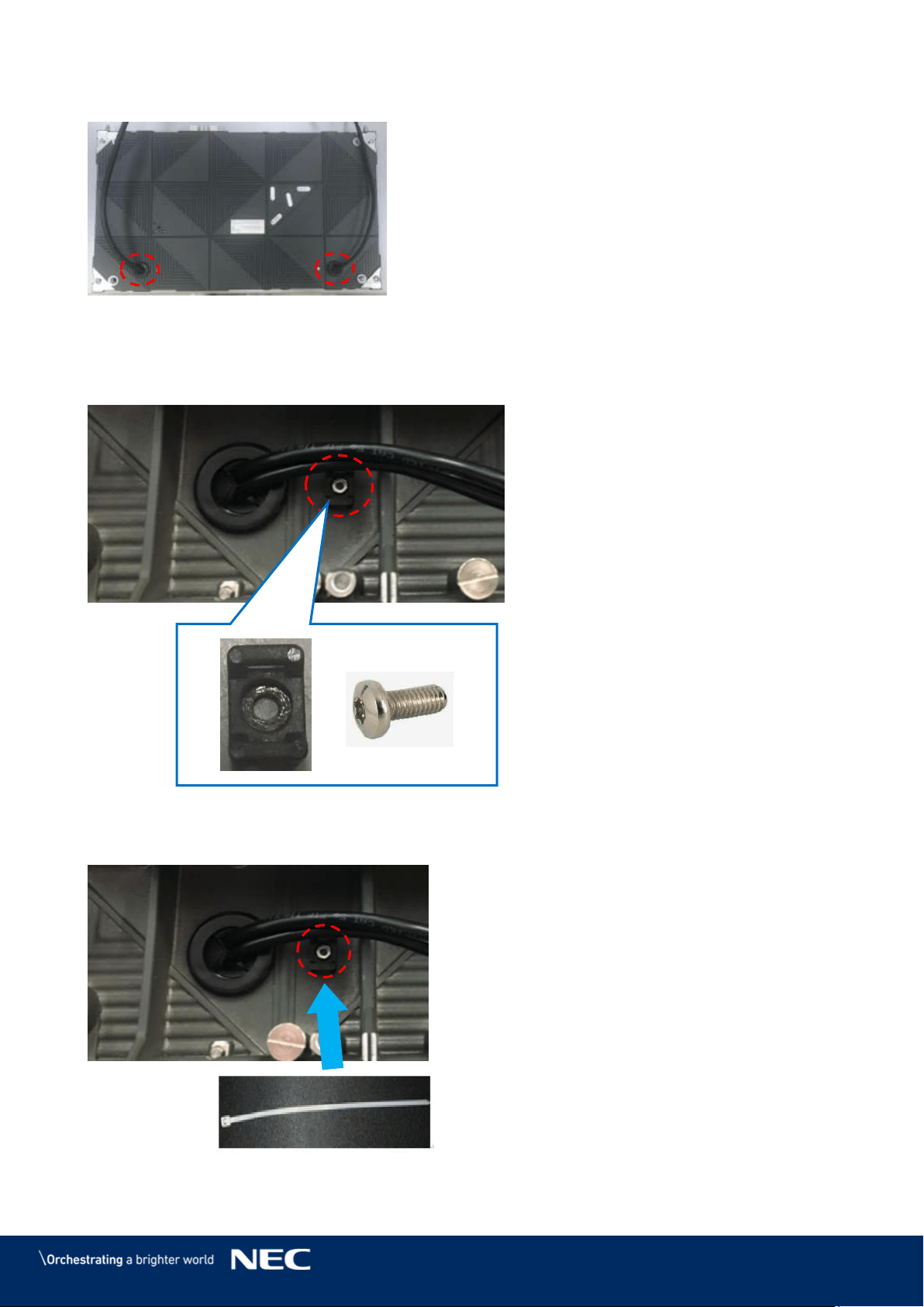
94
Insert the cables Step 2)
Attach the buckle by screw. Step 3)
Through the fastening tie lap Step 4)
Power cable
LAN cable
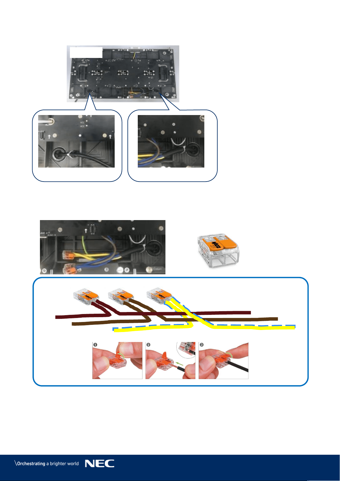
95
Fix the cable to use fastening tie lap Step 5)
Connect the Power cable (inside & outside) like bellows. Step 6)
WAGO (221) is just example to connect the cable. Please arrange on your side.
Front view
Power cable
LAN cable
WAGO 221
Inside power cable
From outside power cable
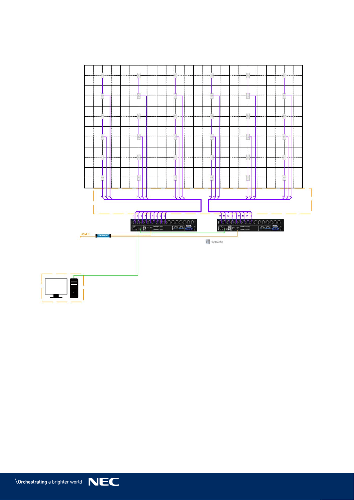
96
15.3
Cable Plans - LED-FE009i2
FE009i2-165" 6x6 0,95mm 3840 x 2160
by client
LED Controller Main 1
LED Controller Main 2
by client
shielded CAT6a
max. length 60m
RJ45 connectors
on both sides
Control PC
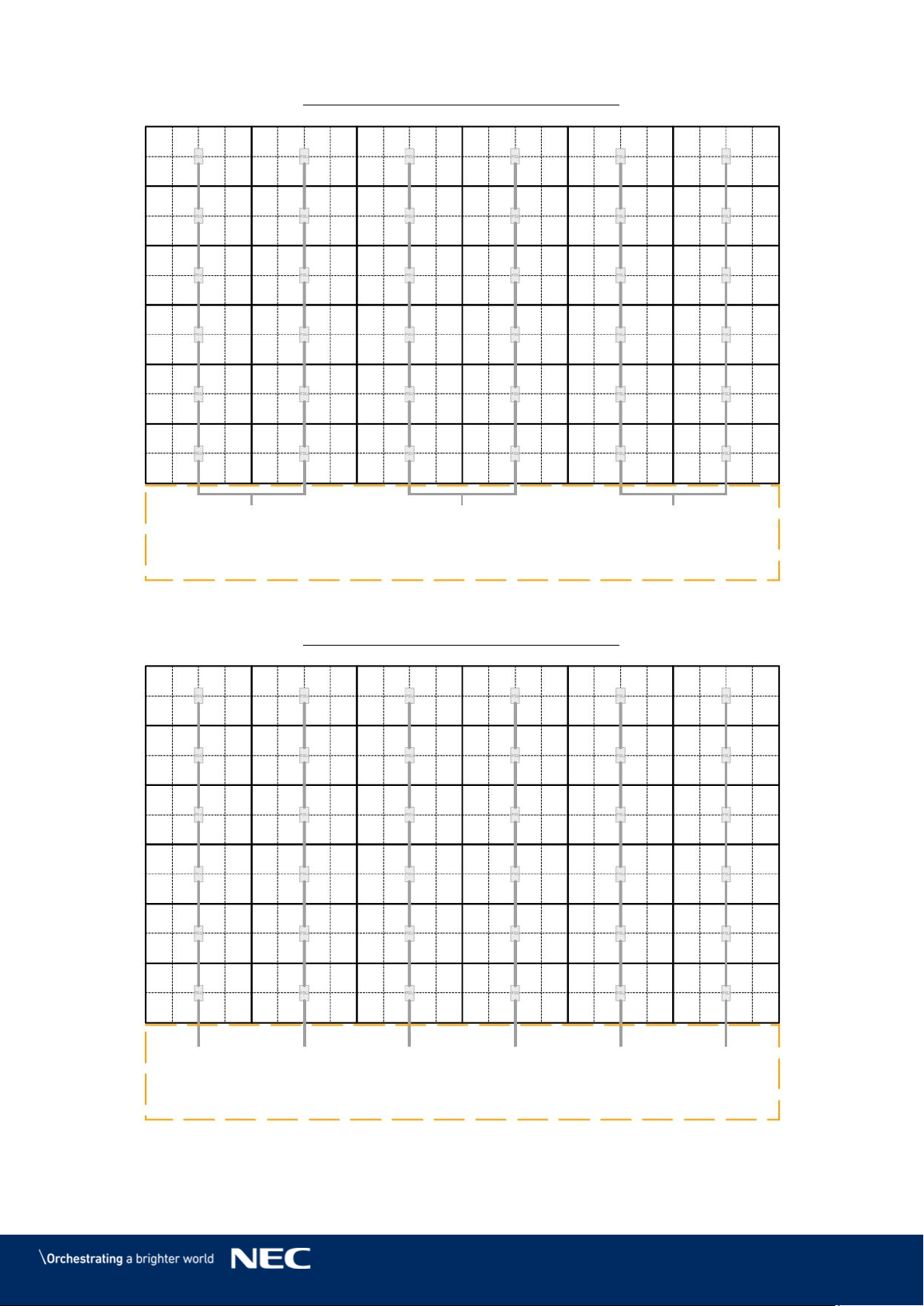
97
FE009i2-165" 6x6 0,95mm 3840 x 2160
FE009i2-165" 6x6 0,95mm 3840 x 2160
200V - 240V
Max. 16A
200V - 240V
Max. 16A
200V - 240V
Max. 16A
100V - 120V
Max. 16A
100V - 120V
Max. 16A
100V - 120V
Max. 16A
100V - 120V
Max. 16A
100V - 120V
Max. 16A
100V - 120V
Max. 16A
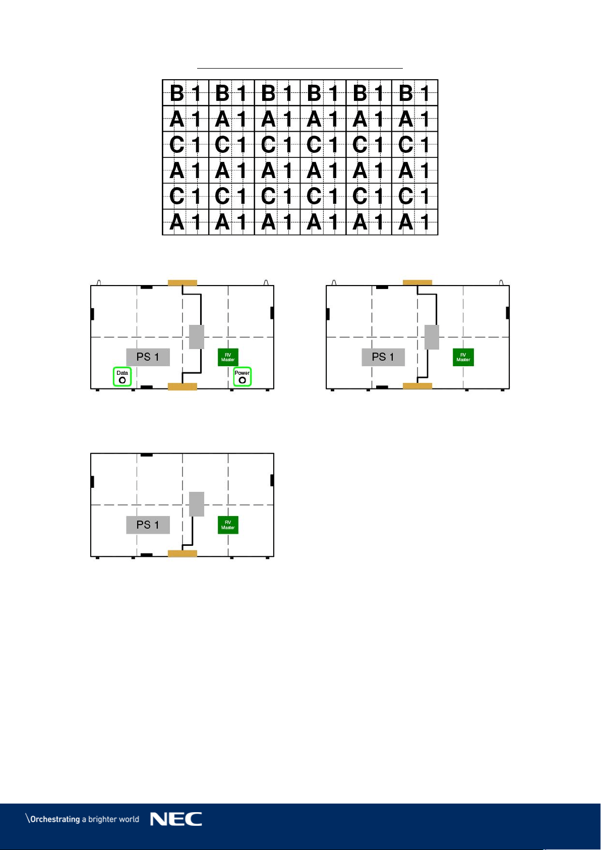
98
FE009i2-165" 6x6 0,95mm 3840 x 2160
terminal
block
terminal
block
terminal
block
A1
(Backside hole cabinet)
C1
(Type A)
B1
(Type B)