Instructions
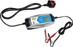
Intelligent Battery Charger
6V/12V 4A
Suitable for 12V Lead Acid, Gel,
Calcium, AGM and EFB batteries between 10-120Ah

2
Intelligent Battery Charger
IMPORTANT SAFETY INSTRUCTIONS
Please save these instructions. This manual contains important safety and operating instructions. Read all instructions and
follow them with each use of this product.
1. SAVE THESE INSTRUCTIONS. This manual contains important safety and operating instructions. You may need to refer to
these instructions at a later date.
2. CAUTION. To reduce risk of injury, charge lead-acid wet cell, gel or AGM automotive type rechargeable batteries. Other types
of batteries may burst causing personal injury and property damage.
3. Do not expose charger to rain or snow.
4. Use of an attachment not recommended or sold by the battery charger manufacturer may result in a risk of fire, electric shock,
or injury to persons.
5. To reduce risk of damage to electric plug and cord, pull by plug rather than cord when disconnecting charger.
6. Make sure cord is located so that it will not be stepped on, tripped over, or otherwise subjected to damage or stress.
7. An extension cord should not be used unless absolutely necessary. Use of improper extension cord could result in a risk of fire
and electric shock. If an extension cord must be used, make sure:
a. The pins on the plug of the extension cord are the same number, size and shape as those of the plug on the charger;
b. That extension cord is properly wired and in good electrical condition;
c. If the length of the extension cord is less than 15 meter, use a 0.75mm2 cord, If 30 metre - 1mm2, 60 meter -1.5mm2.
8. Do not operate charger with damaged cord or plug, replace the cord or plug immediately.
9. Do not operate charger if it has received a sharp blow, been dropped, or otherwise damaged in any way; take it to a qualified
serviceman.
10. Do not disassemble charger; take it to a qualified serviceman when service or repair is required. Incorrect reassembly may
result in a risk of electric shock or fire.
11. To reduce risk of electric shock, unplug charger form outlet before attempting any maintenance or cleaning. Turning off
controls will not reduce this risk.
12. WARNING - RISK OF EXPLOSIVE GASES
a. WORKING IN VICINITY OF A LEAD-ACID BATTERY IS DANGEROUS. BATTERIES GENERATE EXPLOSIVE GASES DURING
NORMAL BATTERY OPERATION. FOR THIS REASON IT IS OF UTMOST IMPORTANCE TO READ THIS MANUAL AND FOLLOW
THE INSTRUCTIONS EXACTLY EACH TIME BEFORE USING CHARGER.
b. To reduce risk of battery explosion, follow these instructions and those published by battery manufacturer and manufacturer
of any equipment you intend to use in vicinity of battery. Review cautionary marking on these products and on engine.
PERSONAL SAFETY PRECAUTIONS
1. Someone should be within range of your voice or close enough to come to your aid when you work near a lead-acid battery.
2. Have plenty of fresh water and soap nearby in case battery acid contacts skin, clothing, or eyes.
3. Wear complete eye protection, and clothing protection. Avoid touching eyes while working near battery.
4. If battery acid contacts skin or clothing, wash immediately with soap and water. If acid enter eye, immediately flood eye with
running cold water for at least 10 minutes and get medical attention immediately.
5. NEVER smoke or allow a spark or flame in vicinity of battery or engine.
6 Be extra cautious to reduce risk of dropping a metal tool onto battery. It might spark or short circuit battery or other electrical
part that may cause explosion.
7. Remove personal metal items such as rings, bracelets, necklaces, and watches when working with a lead-acid battery. A lead-
acid battery can produce a short circuit current high enough to weld a ring or the like to metal, causing a severe burn.
8. Use the charger for charging Lead acid, Gel, Calcium, AGM and EFB batteries. It is not intended to supply power to a low-
voltage electrical system other than in a starter motor application. Do not use battery charger for charging dry-cell batteries
that are commonly used with home appliances. These batteries may burst and cause injury to persons and damage to
property.
9. NEVER charge a frozen battery.
3
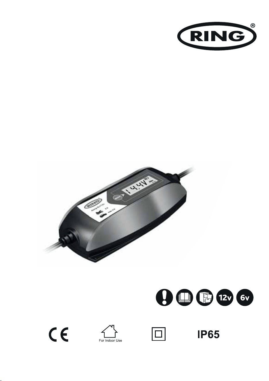
CONTROL PANEL
1. The icon will indicate 2A Charge Rate, which is used for charging the small capacity batteries used in motorcycle, ATV,
snowmobile, personal watercraft, garden tractor and golf car.
2. The icon will indicate 4A Charge Rate, which is used for faster charging of small-to-large capacity automotive, marine, deep
cycle and farm tractor batteries.
3. The icon will appear when selecting the mode of charging in cold state, which means the max charging voltage is 0.2V than
usual.
4. “6V” will appear when selecting the charge for the 6V batteries.
5. “12V” will appear when selecting the charge for the 12V batteries.
6. The icon will indicate the charging process.
7. The numbers or characters will indicate the battery voltage or the error code.
MODE SELECTION BUTTON
Press the Mode Selection Button to select one of the 6 charging modes.
Mode 1: 6V 2A (Icon
1
+
4
will appear)
Mode 2: 6V 2A in the cold state (Icon
1
+
3
+
4
will appear)
Mode 3: 12V 2A (Icon
1
+
5
will appear)
Mode 4: 12V 2A in the cold state (Icon
1
+
3
+
5
will appear)
Mode 5: 12V 4A (Icon
2
+
5
will appear)
Mode 6: 12V 4A in the cold state (Icon
2
+
3
+
5
will appear)
POWER INDICATOR LED
Indicates that the charger is powered on.
REVERSE POLARITY INDICATOR LED
Indicates that the battery clamps are incorrectly connected.

4
FOLLOW THESE STEPS WHEN BATTERY IS INSTALLED IN VEHICLE. A SPARK NEAR BATTERY MAY CAUSE BATTERY
EXPLOSION. TO REDUCE RISK OF A SPARK NEAR BATTERY:
a. Position AC and DC cords to reduce risk of damage by bonnet, door, or moving engine part.
b. Stay clear of fan blades, belts, pulleys, and other parts that can cause injury to persons.
c. Check polarity of battery posts. POSITIVE (POS, P, +) battery post usually has larger diameter than NEGATIVE (NEG, N, -) post.
d. Determine which post of battery is grounded (connected) to the chassis. If negative post is grounded to chassis (as in most
vehicles), see item “e”. If positive post is grounded to the chassis, see item “f”.
e. For negative-grounded vehicle, connect POSITIVE (RED) clamp from battery charger to POSITIVE (POS, P, +) ungrounded post
of battery.
Connect NEGATIVE (BLACK) clamp to vehicle chassis or engine block away from battery. Do not connect clamp to carburettor,
fuel lines, or sheet metal body parts. Connect to a heavy gauge metal part of the frame or engine block.
f. For positive-grounded vehicle, connect NEGATIVE (BLACK) clamp from battery charger to NEGATIVE (NEG, N, -) ungrounded
post of battery. Connect POSITIVE (RED) clamp to vehicle chassis or engine block away from battery. Do not connect clamp to
carburettor, fuel lines, or sheet-metal body parts. Connect to a heavy gauge metal part of the frame or engine block.
OPERATING INSTRUCTIONS
PREPARING TO CHARGE
a. If necessary to remove battery from vehicle to charge, always remove the grounded terminal from battery first. Make sure all
accessories in the vehicle are off, so as not to cause an arc.
b. Be sure area around battery is well ventilated while battery is being charged.
c. Clean battery terminals. Be careful to keep corrosion from coming in contact with eyes.
d. Study all the battery manufacturer’s specific precautions such as removing or not removing cell caps while charging and
recommended rates of charge.
CHARGER LOCATION
a. Locate charger as far away from battery as output cables permit.
b. Never place charger directly above battery being charged; gases from battery will corrode and damage charger.
c. Never allow battery acid to drip on charger when reading gravity or filling battery,
d. Do not operate charger in a closed-in area, or restrict ventilation in any way.
e. Do not set a battery on top of charger.
DC CONNECTION PRECAUTIONS
a. Connect and disconnect DC output clamps only after setting any charger switches to off position and removing ac cord from
electric outlet. Never allow clamps to touch each other.
b. Attach clamps to the battery posts and twist or rock back and forth several times to make a good connection. This tends to keep
the clamps from slipping off terminals and helps to reduce risk of sparking.

5
g. When disconnecting charger, disconnect AC cord, remove clamp from vehicle chassis, and then remove clamp from battery
terminal.
h. See operating instructions for length of charge information.
FOLLOW THESE STEPS WHEN BATTERY IS OUTSIDE VEHICLE. A SPARK NEAR THE BATTERY MAY CAUSE BATTERY
EXPLOSION. TO REDUCE RISK OF A SPARK NEAR BATTERY:
a. Connect POSITIVE (RED) charger clamp to POSITIVE (POS, P, +) post of battery.
b. Position yourself and free end of cable as far away from battery as possible - then connect NEGATIVE (BLACK) charger
clamp to free end of cable.
c. Do not face battery when making final connection.
d. When disconnecting charger, always do so in reverse sequence of connecting procedure and break the first connection
while as far away from battery as practical.
e. A marine (boat) battery must be removed and charged on shore. To charge it on board requires equipment specially
designed for marine use.
AC POWER CORD CONNECTION INSTRUCTIONS
The plug must be plugged into an outlet that is properly installed in accordance with all local codes and ordinances.
DANGER. Never alter AC cord or plug provided - if it will not fit outlet, have proper outlet installed by a qualified electrician.
Improper connection can result in a risk of an electric shock.
LENGTH OF CHARGE
The following instruction will allow you to determine how long it will take to bring a specific battery to full charge.
a. Test the battery for state of charger with a hydrometer or electronic percent-of-charge tester.
b. Determine the size of the battery in Amp-Hour or Reserve Capacity. If the ratings are not printed on the battery, contact
your local battery dealer for this information. These are the only ratings that can be used to determine length to charging
time.
c. Use the battery rating, the charge level of the battery, and amp setting to be used on the charger in the formula provided
below.
Amp Hour Rating of Battery × Percent of Charged Needed × 1.3 = Hours to Charge
Amp Setting Selected On Charger
NOTE: The length of charge times are approximate and varies from the battery to battery. Always follow the battery
manufacturer’s specific charging instructions.
6
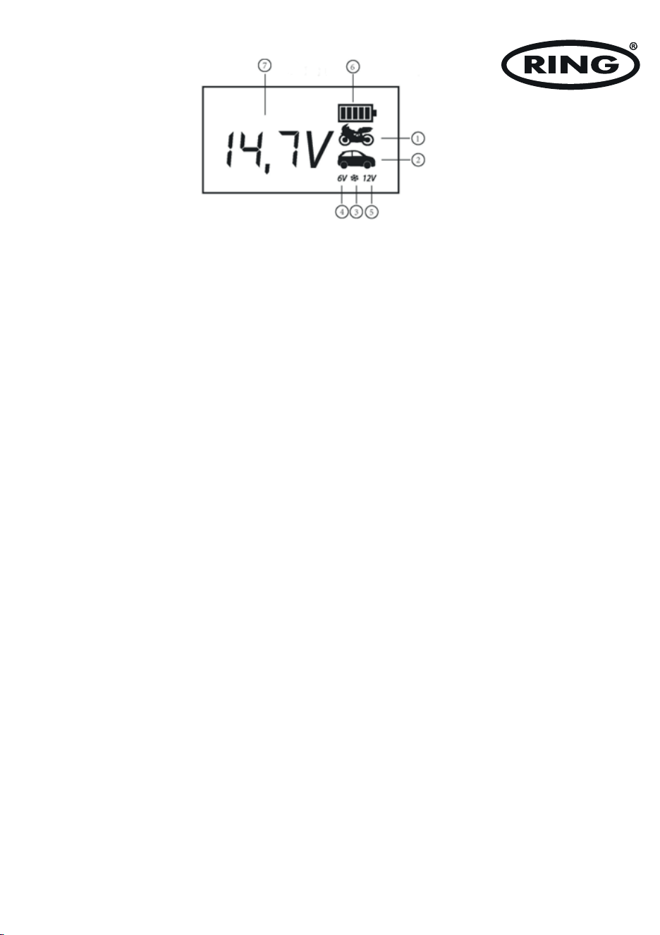
AUTOMATIC CHARGE STAGE
Stage 1 - Diagnosis: Analyse if the battery can accept a charge or not, and then prevent charging from proceeding on the a
defective battery;
Stage 2 - Desulphation: The charger can rescue most drained batteries with voltages up to a Min 1.5±0.5V
Stage 3 - Pre-charge: If the battery voltage is less than 12V, charge it at the smaller current, which will protect the battery better;
Stage 4 - Soft start: Charge the battery to the maximum current gradually and never suddenly.
Stage 5 - CC1/CC2/CC3 (Constant Current): The charger automatically adjusts the current according to the battery status in
constant current, which benefits the battery for a long life;
Stage 6- CV (Constant Voltage): The battery is charged to nearly full, and will top off at 14.6V DC;
Stage 7 - Resting: The charger will cut off with full charged statement, and achieves the high energy efficiency;
Stage 8 - Recondition: When it is fully charged and low to 12.8V within 2min, the charger will judge automatically.
Stage 9 - Restoring: The charger monitors a fully charged battery automatically. If the battery falls below 12.8V DC, the charger
will restart from stage 4 to stage 7.
CHARGING
NOTE: Before using the charger, please review all safety and connection directions. Failure to do so can damage battery
and cause serious injury or death.
· Connect the charger to battery per the operating instructions.
· Connect the charger to AC outlet.
· Select the appropriate charging mode for your batteries.
· If the charger does not detect a properly connected battery, the Reverse Polarity Indicator LED will light or the Error Code will
appear on LCD display until such a battery is detected. Charging will not begin while the Reverse Polarity Indicator LED is on or
the error code disappears. When the charging begins, the charging process Icon on LCD display will appear.
· When charging is completed, unplug the charger from the AC outlet first and then disconnect the batteries with charger.

7
ADDITIONAL FEATURES
a. REVERSE POLARITY PROTECTION
The REVERSE POLARITY INDICATOR LED will light and the power will not be sent to output cables if a reverse connection is
detected.
b. SHORT CIRCUIT PROTECTION
This protection is triggered if the charger detects less than 0.5V across the clamps, and no power will be sent to output cables.
Refer to Error Code of “Er1” in the section of TROUBLESHOOTING ERROR CODES.
c. OVER-VOLTAGE PROTECTION
When the charger is set to charge in a different voltage than the detected voltage of the battery, this protection will be engaged.
Refer to Error Code of “Er1” in the section of TROUBLESHOOTING ERROR CODES.
d. BATTERY DIAGNOSTICS FUNCTION
The charger continuously monitors battery condition and may report certain charging failures as fault codes. Refer to Error Code
of “Er1” and “Er2” in the section of TROUBLESHOOTING ERROR CODES. Conditions that cause the errors include: if the battery
voltage does not rise appropriately during the charging process (indicating a shorted cell) or if the maximum charge time has been
exceeded, etc.
e. BATTERY RECONDITIONING FUNCTION
If a battery is discharged deeply, it could become sulphated and unable to accept a charge. Reconditioning Function may help
reverse the effects of sulphation and restore a batteries ability to accept a charge. If the charger detects a sulphated battery,
it will automatically activate Battery Reconditioning Function. If successful, normal recharging will resume after the battery is
desulphated. If unsuccessful at desulphating the battery, refer to Error Code of “Er2” in the section of TROUBLESHOOTING ERROR
CODES.
f. OVERHEAT PROTECTION
The charger is designed to decrease the charging current and even shut itself off if overheating is detected. Once the charger cools
down, it will resume charging automatically. Refer to Error Code of “Er3” in the section of TROUBLESHOOTING ERROR CODES.
g. MODE-SETTING MEMORY FUNCTION
The microprocessor inside the charger has mode-setting memory function, which means the charger can directly enter into the
mode the users set last time. This function can erase the users’ worry about forgetting the setting for their owner batteries and
shorten the setting time for the users’ convenience.
The housing of the charger is water resistant (IP 65). The first digit – ”6” means protection of humans against the access to
dangerous parts by means of a wire – dust-proof protection.
The second digit ”5” means the protection against the stream of water (12,5 l/min) poured on the housing from any direction. IP
65 apply to housing only, not clamps and AC power lead.

Ring Automotive Limited, Gelderd Road, Leeds LS12 6NA ENGLAND
Tel: +44 (0)113 213 2000 Fax: +44 (0)113 231 0266
Email: [email protected]
Website: www.ringautomotive.com
L493
RECYCLING
This marking indicates that this product should not be disposed with
other household wastes throughout the 2012/19/EU. To prevent possible
harm to the environment or human health from uncontrolled waste
disposal, recycle it responsibly to promote the sustainable reuse of
material resources. To return your used device, please use the return
and collection systems or contact the retailer where the product was
purchased. They can take this product for environmental safe recycling.
MAINTENANCE INSTRUCTIONS
This charger requires minimal maintenance. As with any appliance or tool, a few common sense rules will prolong the life of the
battery charger.
ALWAYS BE SURE THE CHARGER IS UNPLUGGED BEFORE PERFORMING ANY MAINTENANCE OR CLEANING.
1. Store in a clean, dry place
2. Coil up the cords when not in use.
3. Clean the case and cords with a slightly damp cloth.
4. Clean any corrosion from the clamps with a solution of water and baking soda.
5. Examine the cords periodically for cracking or other damage and have them replaced if necessary.
6. WARNING: All other service should be done by qualified personnel only.
TECHNICAL DATA
Model RSC404
Input 220 - 240V AC 50Hz
Output 6V DC 2A 12V DC 2/4A
Error code Condition Possible Cause Solution
Er1
The battery voltage is less than 0.5V
before charging.
The battery is defective. Replace the battery.
The charge does not begin.
The battery clamps are disconnected
with the battery. The battery clamps
are connected to each other.
Connect the battery firmly and
correctly.
The battery voltage is not matched
with the selected mode.
Confirm that battery voltage is
matched with the mode.
Er2
The battery voltage is 0.5V - 1.5V
before charging.
The battery is defective. Replace the battery.
The battery voltage is less than 11V
after 4 minutes of charging. The bat-
tery is not full charged after 24-hour
charge.
The battery is defective. Replace the battery.
A load may be connected to the
battery.
Disconnect the load and attempt to
charge again.
The charge current is too low. Select a higher charge rate.
The battery voltage is less than 12V
in 2 minutes after full charged.
The battery is sulphated beyond
reconditioning.
Replace the battery.
Er3
The temperature of the charger is
too high.
High ambient temperature.
Ensure adequate ventilation. The
charger will resume charging after
cooling.
TROUBLESHOOTING ERROR CODES