Loading ...
Loading ...
Loading ...
10■English
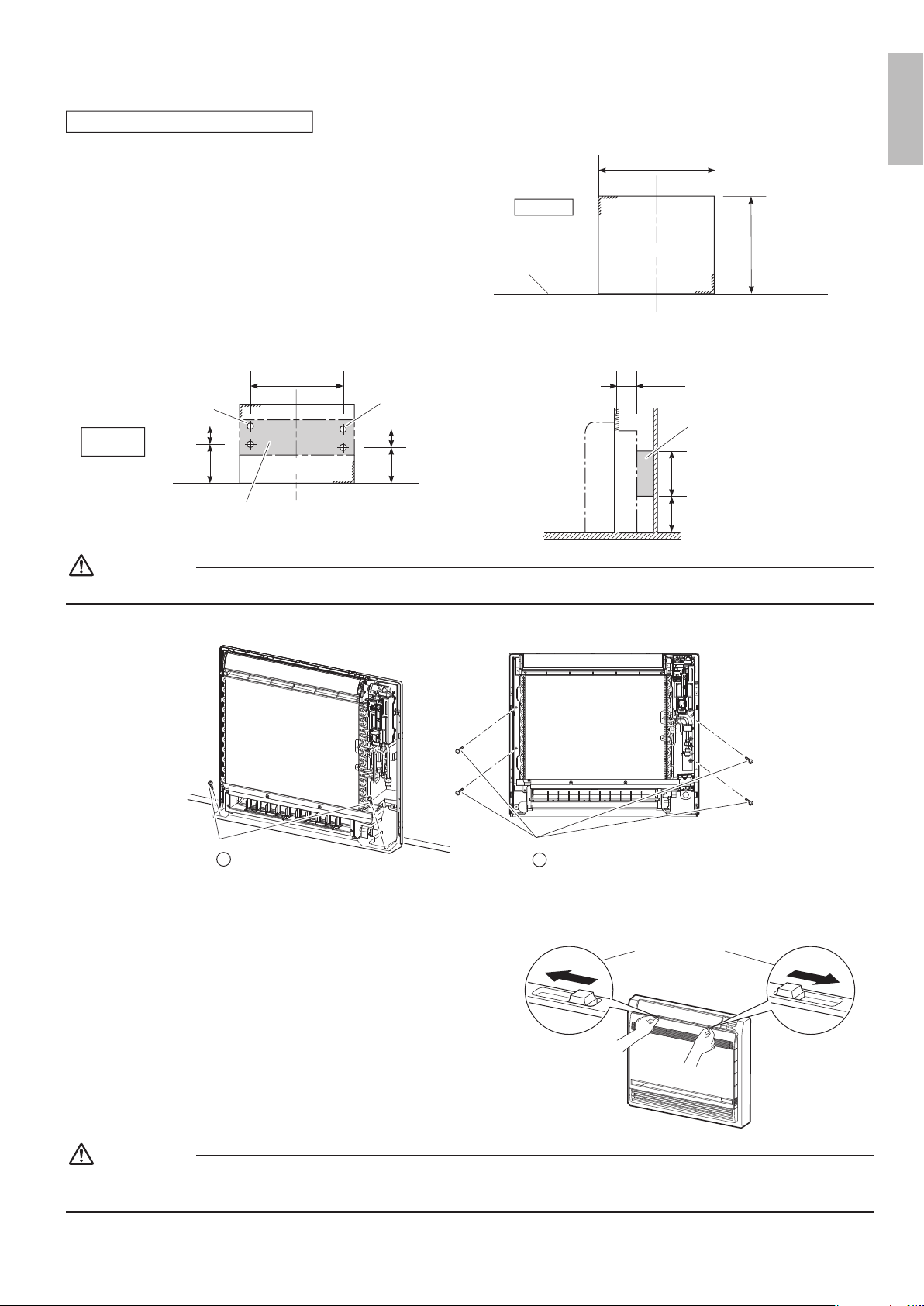
Half concealed installation
1) The size of a wall opening space shown in the illustration on
the right.
26-3/8 – 27-3/16
(670-690)
23-1/16 – 23-7/16
(585 – 595)
unit: inch (mm)
Open size
Opening space
Floor
2) The rear of the unit can be xed with screws at the points shown in the illustration as below. Be sure to install the propping
object in accordance with the depth of the inner wall.
Fixing point
on the back
Propping object
(field supply)
5-1/2 (140)
9-1/16 (230)
25-3/8 (644)
Screw hole
Screw hole
Opening hole
5-7/8 (150)
9-13/16 (250)
3-3/4 (95)
Propping object
(field supply)
9-13/16 (250)
7-7/8 (200)
unit: inch (mm)
CAUTION
The propping object for installing the main unit must be used, or there will be a gap between the unit and the wall.
3) Secure the indoor unit using 6 screws. (2 screws for oor and 4 screws for rear wall)
2 screws
Indoor unit fixing screws
3/16” × 1” (M4 × 25mm)
H
4 screws
Indoor unit fixing screws
3/16” × 1” (M4 × 25mm)
H
4) Once refrigerant piping and drain piping connections are complete, ll in the gap of the through hole with putty.
Any gaps will result in the accumulation of condensation on the refrigerant pipe and drain pipe, as well as allowing
the intrusion of insects and dirt.
5) Attach the left, right and upper casings in their original positions
using 7 screws.
6) Attach the front grill in its original position using 4 screws.
7) Attach the front panel in its original position.
• Attach the string to the right, inner-side of the front grille.
• Close the front panel and slide until the 2 stoppers click outside.
Slide the stoppers
CAUTION
• Use drain pan edge for horizontal projection of the indoor unit.
• Install the indoor unit ush against wall.
English
01_EN_3P379970-7B.indd 10 11/12/2015 13:29:55
Loading ...
Loading ...
Loading ...