Loading ...
Loading ...
Loading ...
Surface Cooking (continued)
Ceramic Glass Cooktop (somemodels)(continued)
Models with Electronic Surface Element Controls (ESEC)
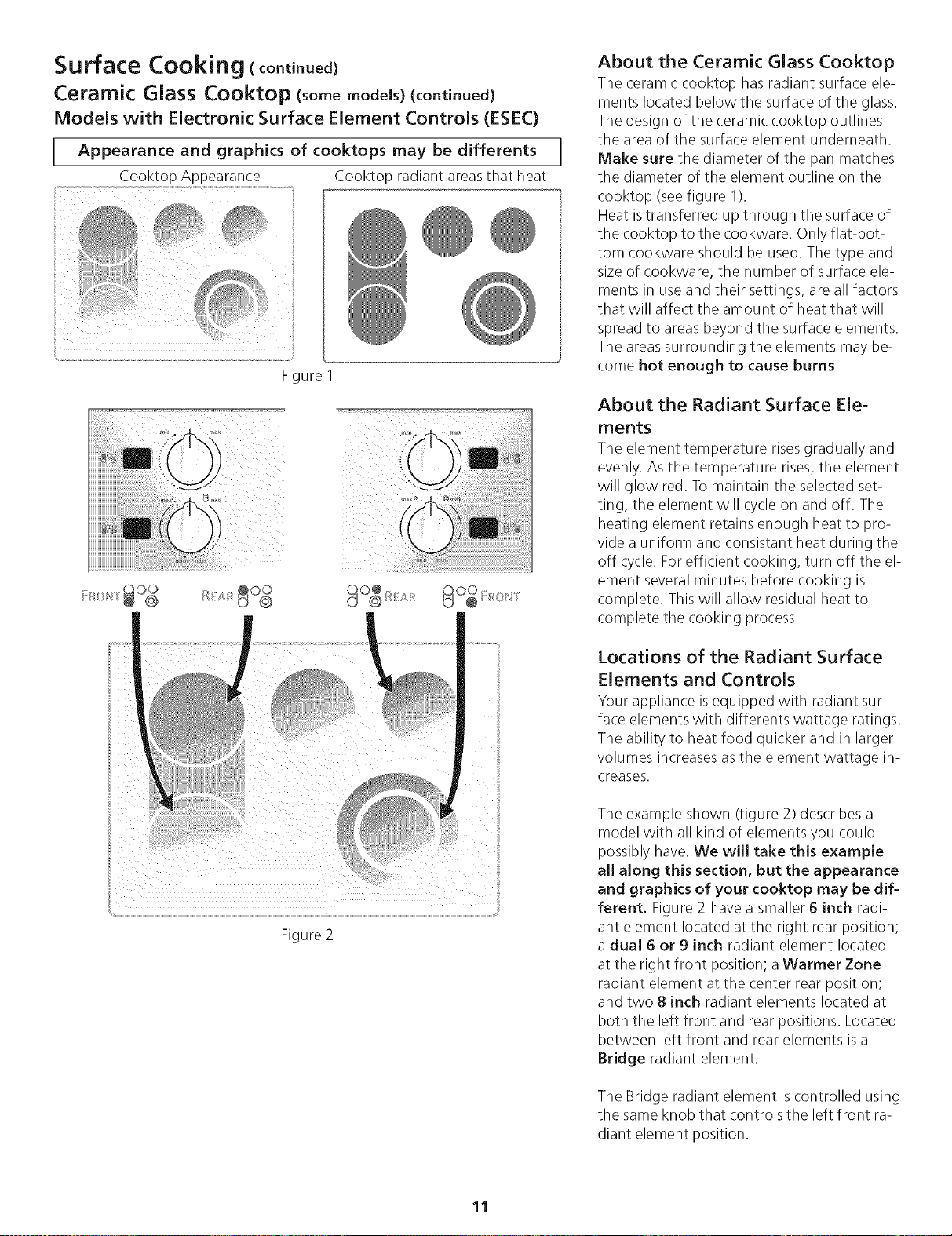
Appearance and graphics of cooktops be differents
may
Cooktop Appearance Cooktop radiant areasthat heat
ii ii_
Figure
g O_ [ I{) s;'/
ii
Figure 2
About the Ceramic Glass Cooktop
The ceramic cooktop has radiant surface ele-
ments located below the surface of the glass.
The design of the ceramic cooktop outlines
the area of the surface element underneath.
Make sure the diameter of the pan matches
the diameter of the element outline on the
cooktop (seefigure I).
Heat istransferred up through the surface of
the cooktop to the cookware. Only flat-bot-
tom cookware should be used. The type and
size of cookware, the number of surface ele-
ments in useand their settings, are all factors
that will affect the amount of heat that will
spread to areas beyond the surface elements.
The areassurrounding the elements may be-
come hot enough to cause burns.
About the Radiant Surface Ele-
ments
The element temperature risesgradually and
evenly. As the temperature rises,the element
will glow red. To maintain the selected set-
ting, the element will cycle on and off. The
heating element retains enough heat to pro-
vide a uniform and consistant heat during the
off cycle. Forefficient cooking, turn off the el-
ement several minutes before cooking is
complete. This will allow residual heat to
complete the cooking process.
Locations of the Radiant Surface
Elements and Controls
Your appliance isequipped with radiant sur-
face elements with differents wattage ratings.
The ability to heat food quicker and in larger
volumes increasesasthe element wattage in-
creases.
The example shown (figure 2) describes a
model with all kind of elements you could
possibly have, We will take this example
all along this section, but the appearance
and graphics of your cooktop may be dif-
ferent. Figure 2 have a smaller 6 inch radi-
ant element located at the right rear position;
a dual 6 or 9 inch radiant element located
at the right front position; a Warmer Zone
radiant element at the center rear position;
and two 8 inch radiant elements located at
both the left front and rear positions. Located
between left front and rear elements isa
Bridge radiant element.
The Bridge radiant element is controlled using
the same knob that controls the left front ra-
diant element position.
11
Loading ...
Loading ...
Loading ...