Loading ...
2
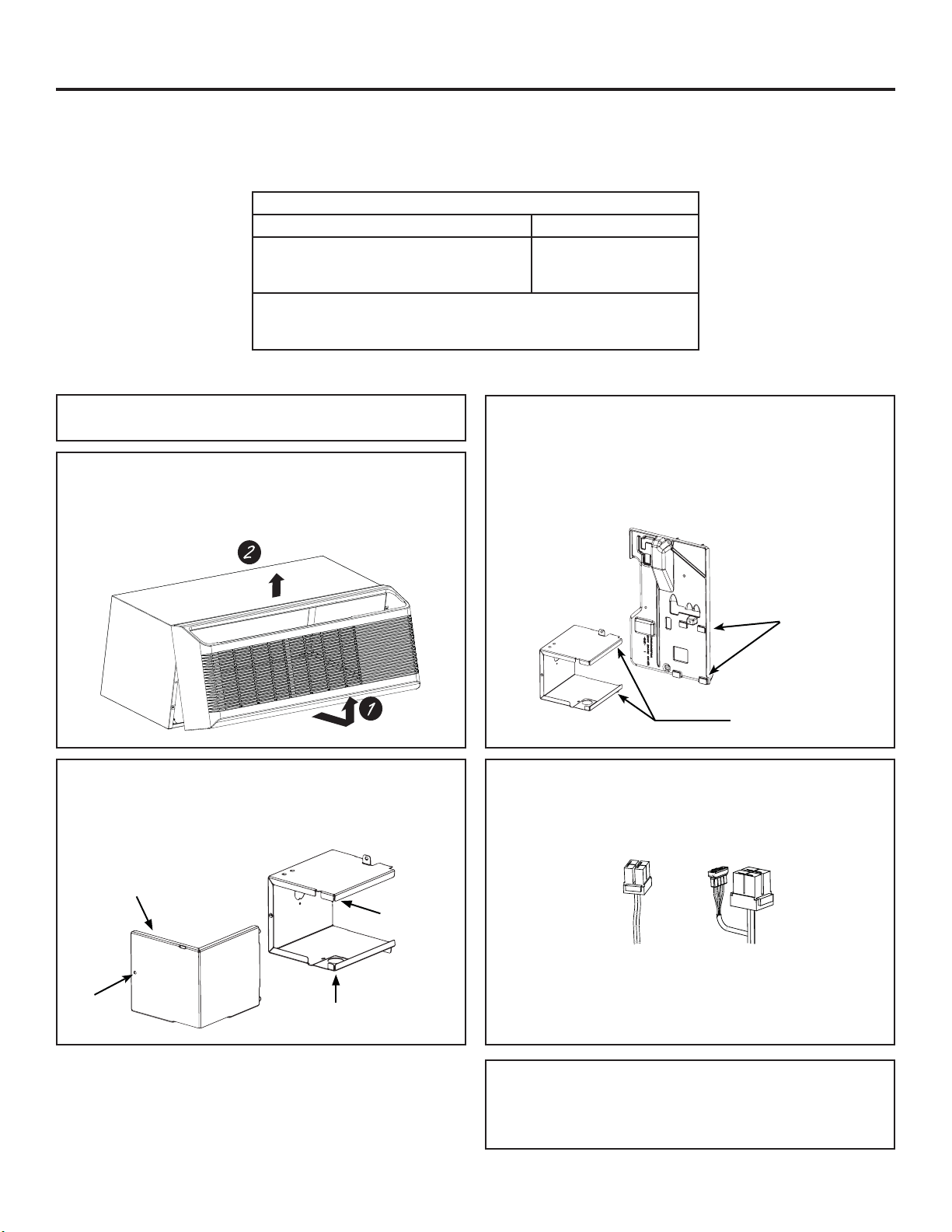
ZONELINE SERIES – DIRECT ELECTRICAL CONNECTION
4. CONNECT THE CORDSET
Plug the connectors, provided in the Direct Connect Kit,
fully into place in the corresponding mating connectors.
Be sure the locking tabs at the sides are engaged.
Installation Instructions
Power supply kit - Appearance may vary
15A 20A and 30A
NOTE: RAK315D and RAK515D will only have
one power connector.
1. REMOVE ROOM FRONT
Remove the room cabinet by pulling it out at the bottom to
release it (1); then lift it up to clear the rail along the unit
top (2)
For a direct connect kit installation with a flex cable,
proceed to step 5A.
For a direct connect kit installation with a sub-base and
chaseway, skip ahead to step 5B.
2. REMOVE JUNCTION BOX COVER
Remove the junction box cover by removing the screw
holding it to the assembly.
3. INSTALL JUNCTION BOX
(230/208V units)
Install the junction box by engaging the left tabs of
the junction box with the slots on the control housing,
align the screw hole at the top and drive the screw until
secure.
It is the responsibility of the installer to ensure the connection of components is done in accordance with the NEC,
local codes, ordinances and regulations.
Direct connection to branch circuit wiring inside the junction box must be made by connecting as follows.
Recommended branch circuit wire sizes*
Nameplate maximum circuit breaker size AWG wire size**
15A
20A
30A
14
12
10
AWG—American Wire Gauge
* Single circuit breaker from main box
** Based on copper wire, single-insulated conductor at 60°C
For GE Zoneline AZ45 & AZ65 Series Units
This kit must be used in conjunction with a GE
RAK4002D junction box kit. Order this kit separately.
Junction box
Junction box
cover
Knock out
Screw
Tabs on
Junction
Box
Slots on
Control
Housing
Loading ...
Loading ...
Loading ...