p/n: 614-40206
Revision 01
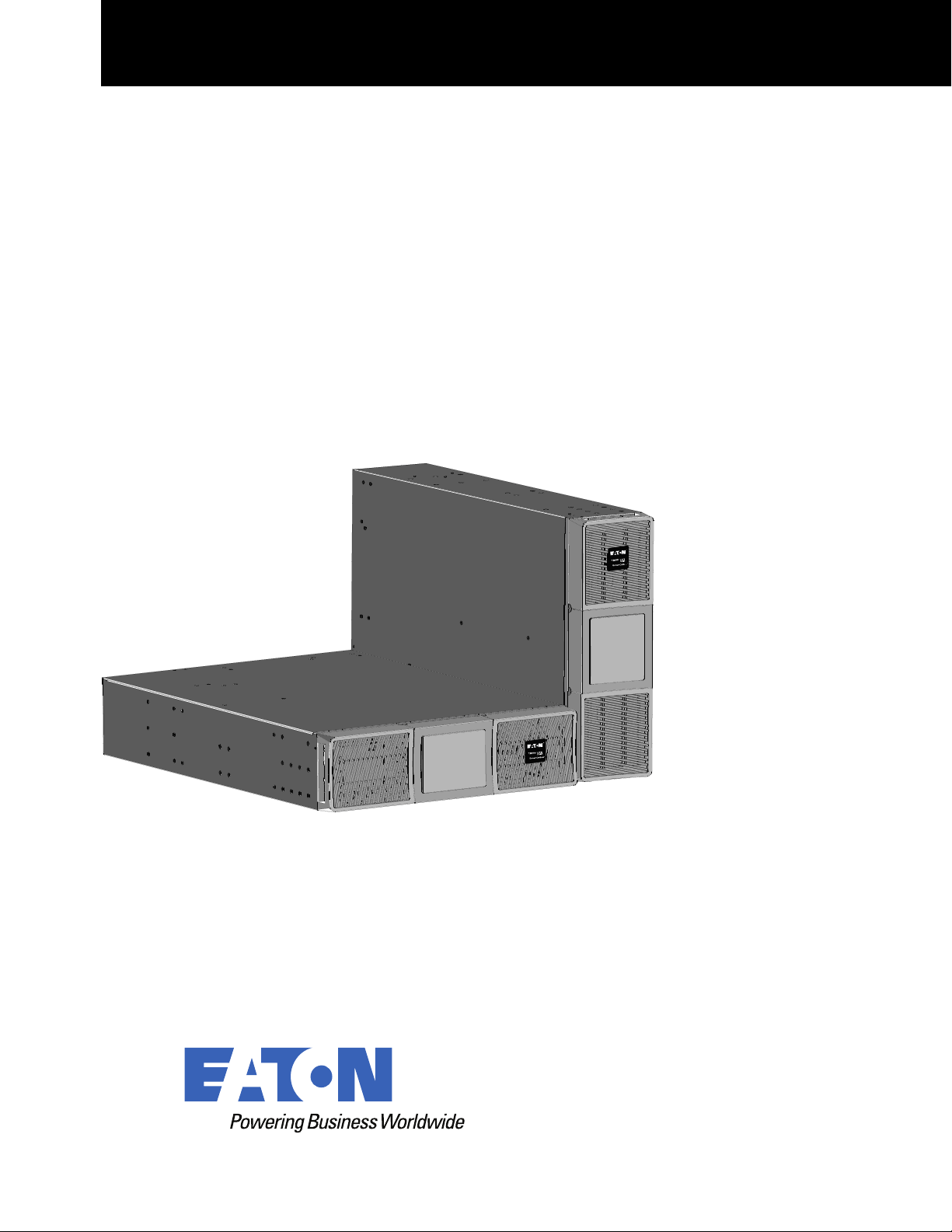
SUTFMR
Transformer Advanced User’s Guide
Eaton Tripp Lite SmartOnline Series

©Copyright 2023 Eaton, Raleigh, NC, USA. All rights reserved. No part of this document may be reproduced in any way without the
express written approval of Eaton.
SSaaffeettyy IInnssttrruuccttiioonnss
SAVE THESE INSTRUCTIONS. This manual contains important instructions that should be
followed during installation and maintenance of the Tripp Lite 5KVA transformer module.
This equipment has been tested and found to comply with the limits for a Class A digital device,
pursuant to Part 15 of the FCC Rules. These limits are designed to provide reasonable protection
against harmful interference when the equipment is operated in a commercial environment. This
equipment generates, uses, and can radiate radio frequency energy and, if not installed and used in
accordance with the instruction manual, may cause harmful interference to radio communications.
Operation of this equipment in a residential area is likely to cause harmful interference in which case
the user will be required to correct the interference at his own expense.
This is a Class A-transformer Product. In a domestic environment, this product may cause radio
interference, in which case, the user may be required to take additional measures.
Suppliers Declaration of Conformity
Unique Identifier: EATON, SUTFMR
Responsible Party:
EATON
10000 Woodward Ave
Woodridge, IL 60517 USA
773–869–1111
tripplite.eaton.com
SSppeecciiaall SSyymmbboollss
The following are examples of symbols used on the product to alert you to important information:
RISK OF ELECTRIC SHOCK - Observe the warning associated with the risk of electric shock
symbol.
CAUTION: REFER TO OPERATOR'S MANUAL - Refer to your operator's manual for
additional information, such as important operating and maintenance instructions.
This symbol indicates that you should not discard the transformer or the transformer batteries
in the trash. This product contains sealed, lead-acid batteries and must be disposed of
properly. Contact your local recycling/reuse or hazardous waste center for more information.
This symbol indicates that you should not discard waste electrical or electronic equipment
(WEEE) in the trash. For proper disposal, contact your local recycling/reuse or hazardous
waste center.

SSaaffeettyy ooff PPeerrssoonnss
The transformer contains LETHAL VOLTAGES. All repairs and service should be performed by
AUTHORIZED SERVICE PERSONNEL ONLY. There are NO USER-SERVICEABLE PARTS inside the
transformer.
PPrroodduucctt SSaaffeettyy
• Changes or modifications not expressly approved by the party responsible for compliance can
void the user’s authority to operate the equipment.
• To connect the transformer, follow the instructions and operations described this manual in the
indicated order.
• Check that the indications on the rating plate correspond to your AC-powered system and to the
actual electrical consumption of all the equipment to be connected to the system.
• For PLUGGABLE EQUIPMENT, the socket-outlet shall be installed near the equipment and shall
be easily accessible.
• Never install the system near liquids or in an excessively damp environment. This equipment
should only be used in a dry, indoor environment.
• This unit is intended for installation in a controlled environment (temperature-controlled, indoor
area free of conductive contaminants). Avoid installing the transformer in locations with standing
or running water or excessive humidity.
• Ensure that the system is free of any contaminants, that the surrounding area is free of debris,
and that there are no foreign substances within the system.
• In the event of an emergency, disconnect the power cord from the AC power supply to properly
disable the transformer.
• Avoid covering the unit's cooling vents to reduce the risk of overheating the transformer.
• Do not allow any liquids to enter the transformer. Do not place beverages or any other liquid-
containing vessels on or near the unit.
• Never expose the system to direct sunlight or to a heat source.
• Store the system in a dry place before installing, if storage is required.
• Do not attach non-computer-related items, such as medical equipment, life-support equipment,
microwave ovens, or vacuum cleaners, to a transformer.
• Unplug the transformer prior to cleaning, and do not use liquid or spray detergent.
• Avoid exposing the transformer to direct sunlight or installing the unit near heat-emitting
appliances such as space heaters or furnaces.
• The system is not for use in a computer room AS DEFINED IN the standard for the Protection of
Information Technology Equipment, ANSI/NFPA 75 (US installations only).
• The system must be properly grounded at all times.
• The admissible storage temperature range is -25°C to +55°C without batteries, 0°‹C to 40°C with
batteries.
SSppeecciiaall PPrreeccaauuttiioonnss
• The unit is heavy: wear safety shoes and preferentially use a vacuum lifter for handling
operations.
• All handling operations will require at least two people (unpacking, lifting, installation in the rack
system).


Eaton Tripp Lite SmartOnline Series User Guide 614-40206—Rev 01 v
TTaabbllee ooff CCoonntteennttss
11 IInnttrroodduuccttiioonn....................................................................................................................................................................................................................................................................................................11
1.1 Introduction............................................................................................................................................... 1
1.2 Environmental Protection .............................................................................................................................1
22 PPrreesseennttaattiioonn ..................................................................................................................................................................................................................................................................................................33
2.1 Standard Installations ..................................................................................................................................3
2.2 Rear Panel ................................................................................................................................................4
33 IInnssttaallllaattiioonn ......................................................................................................................................................................................................................................................................................................55
3.1 Inspecting the Equipment............................................................................................................................. 5
3.2 Unpacking the Cabinet.................................................................................................................................5
3.3 Checking the Accessory Kit ..........................................................................................................................6
3.4 Tower Installation ....................................................................................................................................... 6
3.5 Rack Installation .........................................................................................................................................7
44 EElleeccttrriiccaall IInnssttaallllaattiioonn...................................................................................................................................................................................................................................................................... 1111
4.1 Transformer Electrical Connections .............................................................................................................. 11
55 SSeerrvviiccee aanndd SSuuppppoorrtt ........................................................................................................................................................................................................................................................................ 1155
5.1 Service and Support .................................................................................................................................. 15
66 SSppeecciiffiiccaattiioonnss.......................................................................................................................................................................................................................................................................................... 1177
6.1 Model Specifications ................................................................................................................................. 17


Eaton Tripp Lite SmartOnline Series User Guide 614-40206—Rev 01 1
CChhaapptteerr 11 IInnttrroodduuccttiioonn
11..11 IInnttrroodduuccttiioonn
Thank you for selecting an Eaton Tripp Lite SmartOnline Series product to protect your electrical equipment.
The Eaton Tripp Lite SmartOnline Series step-down transformer has been designed with the utmost care.
We recommend that you take the time to read this manual to take full advantage of the many features of your
SmartOnline Series Transformer.
Before installing your system, please read the booklet presenting the safety instructions. Then follow the
indications in this manual.
To discover the entire range of products and the options available for the Eaton Tripp Lite SmartOnline Series
product line visit tripplite.eaton.com or contact your Eaton Tripp Lite SmartOnline Series representative.
11..22 EEnnvviirroonnmmeennttaall PPrrootteeccttiioonn
Eaton has implemented an environmental-protection policy.
Products are developed according to an eco-design approach.
Substances
This product does not contain CFCs, HCFCs, or asbestos.
Packing
To improve waste treatment and facilitate recycling, separate the various packing components.
• The cardboard we use is comprised of over 50% recycled cardboard.
• Sacks and bags are made of polyethylene.
• Packing materials are recyclable and bear the appropriate identification symbol
01
PET
Table 1. Packing Material Symbols
Materials Abbreviations Number in the symbols
Polyethylene terephthalate PET
01
High-density polyethylene HDPE 02
Polyvinyl chloride PVC
03
Low-density polyethylene LDPE 04
Polypropylene PP 05
Polystyrene PS
06
Follow all local regulations for the disposal of packing materials.
End of Life
Eaton will process products at the end of their service life in compliance with local regulations. Eaton works
with companies in charge of collecting and eliminating our products at the end of their service life.

2 Eaton Tripp Lite SmartOnline Series User Guide 614-40206—Rev 01
Product
The product is made mainly of recyclable materials.
Dismantling and destruction must comply with all local regulations concerning waste. At the end of its service
life, the product must be transported to a processing center for electrical and electronic waste.
Benefits
The Eaton Tripp Lite Series Step Down Transformer is designed to operate as an accessory with the
SmartOnline SU5000RT /SU6000RT uninterruptible power systems (UPSs).
• Backed by worldwide agency approvals.
• Can be installed in a rack or tower configuration.
• Voltage selection for 208 VAC or 240 VAC input.
• The main outlet options on the transformer module include (18) 5-20R
• The transformer module is 3U in height and has a three foot input L6–30 line cord.
Environmental Protection

Eaton Tripp Lite SmartOnline Series User Guide 614-40206—Rev 01 3
CChhaapptteerr 22 PPrreesseennttaattiioonn
22..11 SSttaannddaarrdd IInnssttaallllaattiioonnss
Figure 1. UPS Dimensions
D
W
H
D
H
W
Table 2. Weights and Dimensions
Description Weights
(lb/kg)
Dimensions (inch/mm)
D x W x H
SUTFMR 95 / 48 24.5 x 17.3 x 5.1 / 622 x 440 x 130

4 Eaton Tripp Lite SmartOnline Series User Guide 614-40206—Rev 01
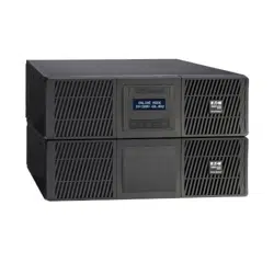
22..22 RReeaarr PPaanneell
Figure 2. SUTFMR
(9)
5-20R
SUTFMR L2 Receptacle Group
208V: When the input voltage is 208V, the total output current maximum for the L2 receptacle group is 22.1A.
240V: When the input voltage is 240V, the total output current maximum for the L2 receptacle group is 22.5A.
(9)
5-20R
SUTFMR L1 Receptacle Group
208V: When the input voltage is 208V, the total output current maximum for the L1 receptacle group is 22.1A.
240V: When the input voltage is 240V, the total output current maximum for the L1 receptacle group is 22.5A.
L6-30 input line cord
L6-30 input line cord
Main circuit breaker
Main circuit breaker
Circuit breaker 120V 20A
Circuit breaker 120V 20A
Rear Panel

Eaton Tripp Lite SmartOnline Series User Guide 614-40206—Rev 01 5
CChhaapptteerr 33 IInnssttaallllaattiioonn
33..11 IInnssppeeccttiinngg tthhee EEqquuiippmmeenntt
If any equipment has been damaged during shipment, keep the shipping cartons and packing materials for the
carrier or place of purchase, and file a claim for shipping damage. If you discover damage after accepting the
equipemnt, file a claim for concealed damage.
To file a claim for shipping damage or concealed damage:
1. File with the carrier within 15 days of receipt of the equipment;
2. Send a copy of the damage claim to a Eaton service representative within 15 days.
33..22 UUnnppaacckkiinngg tthhee CCaabbiinneett
Unpacking the cabinet in a low-temperature environment may cause condensation to occur in and on the
cabinet. Do not install the cabinet until the inside and outside of the cabinet are absolutely dry (risk of electric
shock).
The cabinet is heavy. Follow special precautions provided and on the carton.
Unpack the equipment and remove all of the packing materials and shipping carton.
NOTE Do not lift the transformer from the front panel.
Discard or recycle the packaging responsibly, or store it for future use. Place the cabinet in a protected area
with adequate airflow that is free of humidity, flammable gas, and corrosive elements.
Packing materials must be disposed of in compliance with all local regulations concerning waste. Recycling
symbols are printed on the packing materials to facilitate sorting.

6 Eaton Tripp Lite SmartOnline Series User Guide 614-40206—Rev 01
33..33 CChheecckkiinngg tthhee AAcccceessssoorryy KKiitt
Verify that the following additional items are included with the Transformer:
Figure 3. SUTFMR
Rackmount mounting brackets
Rack kit for 19-inch enclosures
Quick start
Safety instructions
Stabilizer bracket
1
2
3
4
5
1
3
2
5
4
NOTE If you ordered other UPS accessories, refer to their specific user manuals to check the
packing contents.
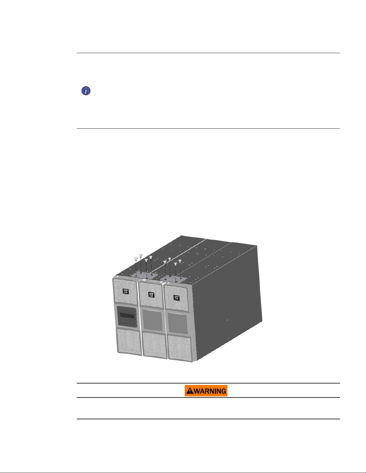
33..44 TToowweerr IInnssttaallllaattiioonn
DO NOT install the transformer in a hermetically-closed environment without any exchange of air.
The transformer is heavy. A minimum of two people are required to lift the cabinet.
Checking the Accessory Kit
Eaton Tripp Lite SmartOnline Series User Guide 614-40206—Rev 01 7
NOTE 1 The order of a tower installation, from left to right, is the SmartOnline Transformer,
SmartOnline EBM (If applicable), and the SmartOnline 5000 / 6000 UPS.
NOTE 2 Eaton recommends a minimum of 150 mm (5.9") of free space behind the UPS rear
panel.
NOTE 3 Joining brackets are required to stabilize the upright cabinets in installations with two or
more cabinets. A joining bracket is provided in the transformer accessory box in the
shipping carton.
NOTE 4 If you are adding a cabinet to an existing tower configuration, only add a single joining
bracket between the transformer and the next cabinet in the configuration.
To set up a tower configuration:
1. Do this only if the UPS is already installed and operating: Shut down the UPS before installing the
SmartOnline Transformer. Refer to shutdown instructions in the appropriate SmartOnline UPS user's
guide for your system configuration.
2. Position the cabinet upright. Turn the Eaton logo to align with the top of the cabinet. Ensure additional
cabinets are upright.
3. Group the cabinets in the correct order.
4. Locate the joining bracket in the rail kit box.
5. Align each joining bracket with the adjacent cabinet screw holes and secure with the supplied screws.
Figure 4. Joining Brackets
33..55 RRaacckk IInnssttaallllaattiioonn
Shut down the UPS before installing transformer. Refer to the shutdown instructions in the appropriate
SmartOnline UPS User's Guide for your system configuration.
Rack Installation

8 Eaton Tripp Lite SmartOnline Series User Guide 614-40206—Rev 01
Follow these steps to mount the SmartOnline Transformer on the rails.
1
1
2
3
3
4
4
NOTE If you have other accessories, the order of a rack-mount installation, from top to bottom,
is the SmartOnline UPS, SmartOnline EBM, and the SmartOnline Transformer. Refer to
the UPS or EBM documentation to check the rack-mounted installation procedure for
those products.
Rack Installation


Eaton Tripp Lite SmartOnline Series User Guide 614-40206—Rev 01 11
CChhaapptteerr 44 EElleeccttrriiccaall IInnssttaallllaattiioonn
44..11 TTrraannssffoorrmmeerr EElleeccttrriiccaall CCoonnnneeccttiioonnss
Risk of electrical shock. Only qualified service personnel (such as a licensed electrician) shall perform the
electrical installation.
Do not make unauthorized changes to the SmartOnline Transformer Module. This may damage your
equipment and void your warranty.
For pluggable equipment, the socket-outlet shall be installed near the equipment and easily accessible.
The SmartOnline transformer module requires a 30A circuit with short circuit and overcurrent protection.
For SmartOnline transformer configurations, the AC input from the transformer connects to the UPS, then the
UPS connects to the mains.
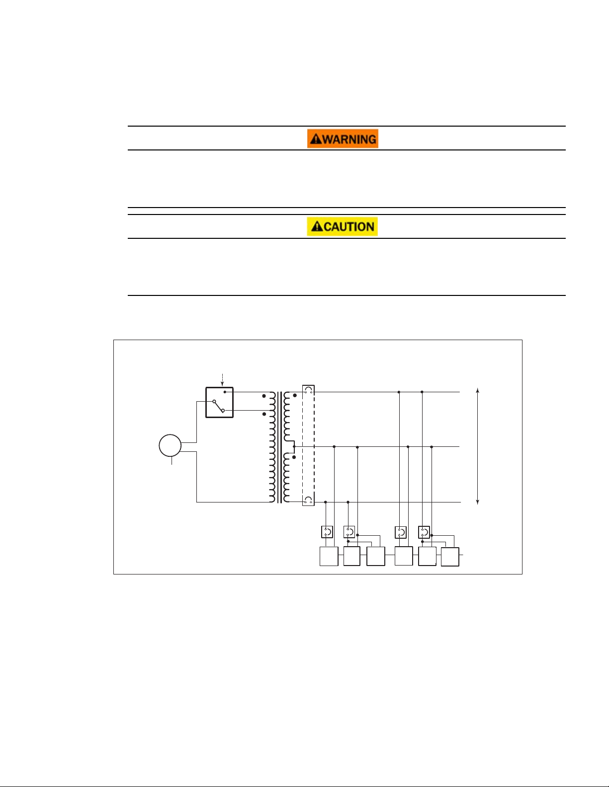
Figure 6. SmartOnline Transformer Block Diagram
30A CB
Voltage selection
(To UPS
output)
Transformer
AC input
Transformer
AC input
L1
L2
N
120
120
5-20R
(x3)
20A CB
20A CB
20A CB
20A CB
L1
L2
G
G
5-20R
(x3)
5-20R
(x3)
5-20R
(x3)
L6-30P
30A
5-20R
(x3)
5-20R
(x3)
1. Verify that the transformer output circuit breaker is in the OFF position.
2. On the transformer front cover, unsnap and remove the square center cover.

12 Eaton Tripp Lite SmartOnline Series User Guide 614-40206—Rev 01
Figure 7. Remove Center Cover
Remove screws
3. Remove and retain the two left-side Phillips-head screws that secure the front cover.
4. Open the front cover from the left side.
Figure 8. Open Left Cover
208V
2
4
0
V
5. Turn the voltage select switch to the proper voltage setting. See Table 3.
NOTE All high-voltage outlets on the back of the transformer use the UPS output voltage. All
low-voltage receptacles use the transformer, and the voltage switch determines the
voltage.
NOTE When the transformer voltage selection switch is set to the 240V position with 240V
input, the output voltage is 240/120V. When the voltage selection is set to 208V, with
208V input, the output voltage is 240/120V.
Transformer Electrical Connections

Eaton Tripp Lite SmartOnline Series User Guide 614-40206—Rev 01 13
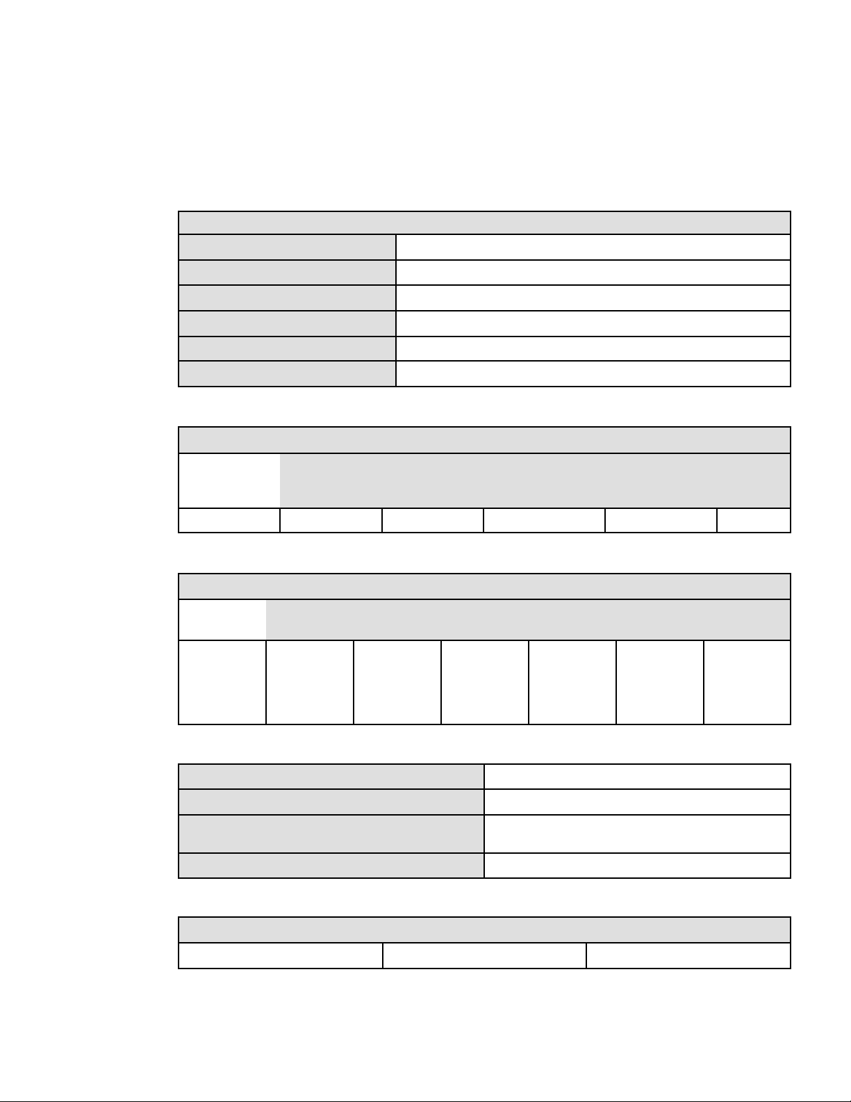
Table 3. SmartOnline Transformer I/O Output Voltage
Input voltage SmartOnline transformer output voltage
(from UPS)
208V Switch position 240V Switch position
5–20R 5–20R
200 115 100
208 120 104
220 127 110
230 133 115
240 138 120
250 144 125
6. Close the front cover and secure it with the two phillips-head.
7. Replace the square center cover.
8. Plug the transformer into one of the L6–30 receptacles on the back of the UPS. See
Figure 9 and Figure 10
.
NOTE Refer to the UPS User's Guide for additional installation and system configuration
information.
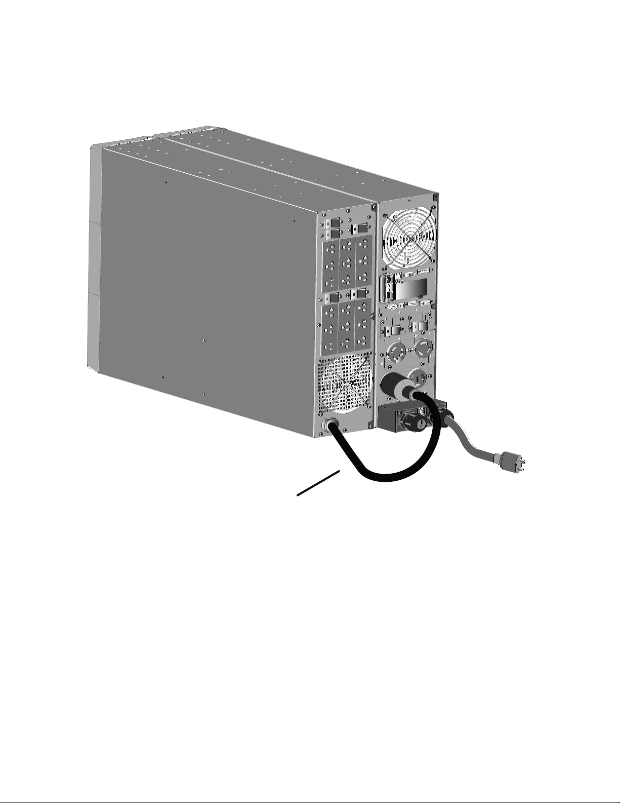
Figure 9. Rack-mounted Transformer Electrical Connection
Transformer connected
to UPS output
Transformer Electrical Connections

Eaton Tripp Lite SmartOnline Series User Guide 614-40206—Rev 01 15
CChhaapptteerr 55 SSeerrvviiccee aanndd SSuuppppoorrtt
55..11 SSeerrvviiccee aanndd SSuuppppoorrtt
If you have any questions or problems with the UPS, call your Local Distributor or Eaton Support at one of
the following telephone numbers and ask for a UPS technical representative.
United States:
1–800–356–5737
Canada:
1–800–461–9166 ext 260
All other countries: Call your local service representative
Please have the following information ready when you call Eaton Support:
• Model number
• Serial number
• Version number (if available)
• Date of failure or problem
• Symptoms of failure or problem
• Customer return address and contact information
If repair is required, you will be given a Returned Material Authorization (RMA) number. This number must
appear on the outside of the package and on the Bill Of Lading (if applicable). Use the original packaging or
request packaging from Eaton Support or your local distributor. Units damaged in shipment as a result of
improper packaging are not covered under warranty. A replacement or repair unit will be shipped, and freight
prepaid for all units within the warranty period.
NOTE For critical applications, immediate replacement may be available. Call Eaton Support
for the dealer or distributor nearest you.

Eaton Tripp Lite SmartOnline Series User Guide 614-40206—Rev 01 17
CChhaapptteerr 66 SSppeecciiffiiccaattiioonnss
66..11 MMooddeell SSppeecciiffiiccaattiioonnss
Table 4. Mechanical and Environmental
SUTFMR
Operating temperature 0°C to 40°C (32°F to 104°F)
Storage temperature -22°C to 55°C (-7°F to 131°F)
Relative humidity 0–95% noncondensing
Altitude
10% derating over 1000m (The altitude shall not exceed 3000m.)
Dimensions (W x D x H)
24.5 x 17.3 x 5.1 / 622 x 440 x 130
Weight
48 kg (95 lb)
Table 5. Input Specifications
Input ( Sine wave waveform)
Input voltage Input current Input voltage range
(UPS on bypass AC
mode)
Frequency range Input
protection
SUTFMR 208V/240V 24A Full load above 200V
60 Hz (± 3 Hz)
none
Table 6. Output Specifications
Output ( Sine wave waveform)
Nominal
power
Output
voltage
Efficiency Voltage
adjustable
Frequency
range
Output
protection
SUTFMR 5000 VA,
5000W
120V (2)
isolated
>92% Linear
load
4%
60Hz (± 3 Hz) (1) UL 489 type,
30A double-
pole CB (4) UL
489 type, 20A
CB
Table 7. Standards
Safety conformance IEC 62040-1:2008, UL 1778 4th; CSA C22.2
Agency markings
cULus, CE, NOM
EMC (Class A) IEC 62040-2:2006 categories C2, CISPR22 Class A, FCC Part 15,
Class A
Insulation
EN 61558-1-2-4 (TFMR 1.5kV/5MOhms)
Table 8. Power Connection
Model Input connection Output outlets
SUTFMR One L6-30P power cord 0.9m (2.3 ft) (18) 5-20R

614-4020601
614-40206 01