Loading ...
Loading ...
Loading ...
Removethehairpinclipwhichsecuresthespeed
controlrod'sferruletothespeedbracket.See
Figure17.
Atthefactory,thespeedcontrolrodisadjustedsothat
5/8-in.oftherodisexposedbeyondtheferrule.
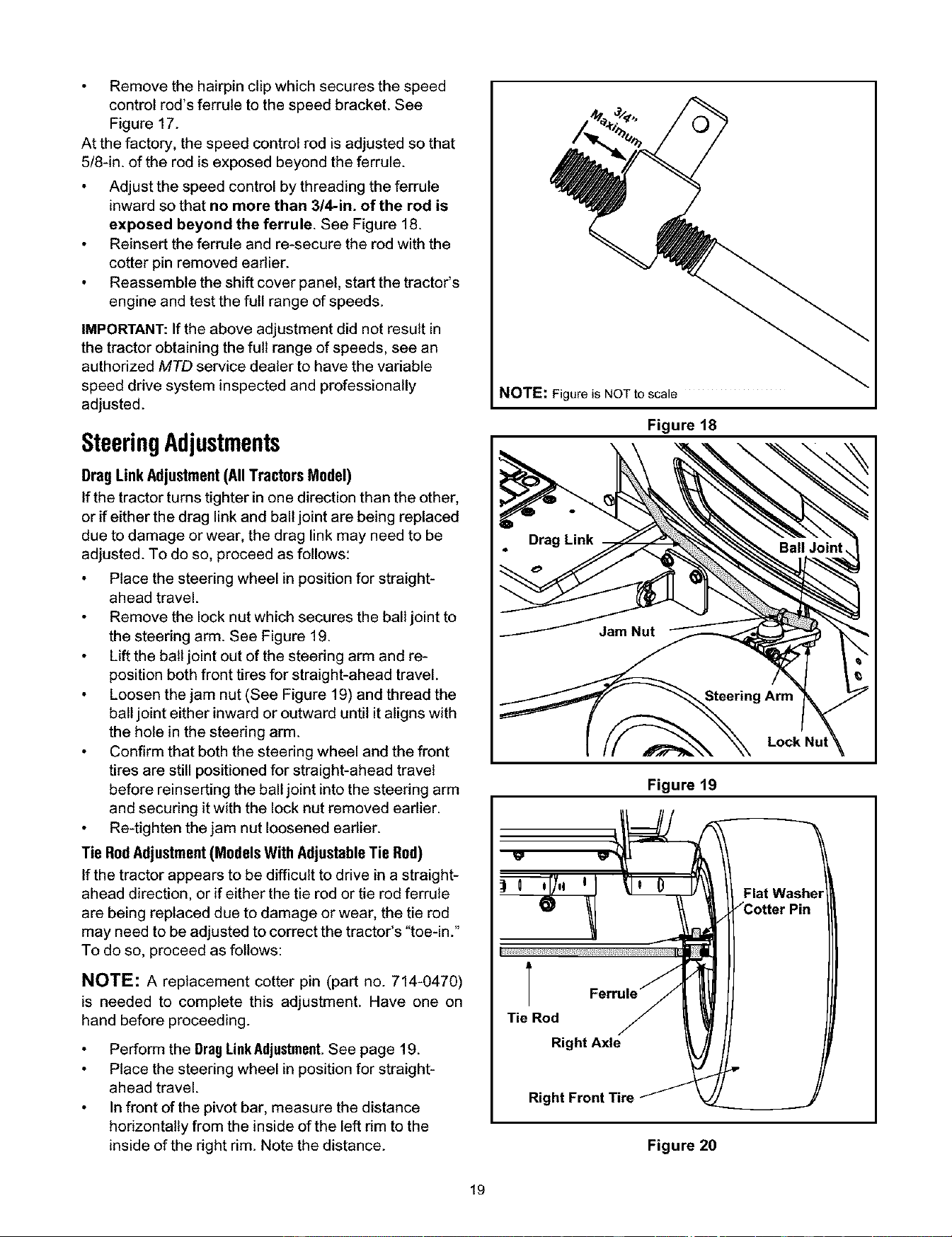
Adjustthespeedcontrolbythreadingtheferrule
inwardsothatnomorethan3/4-in.oftherodis
exposedbeyondtheferrule.SeeFigure18.
Reinserttheferruleandre-securetherodwiththe
cotterpinremovedeadier.
Reassembletheshiftcoverpanel,startthetractor's
engineandtestthefullrangeofspeeds.
IMPORTANT:Iftheaboveadjustmentdidnotresultin
thetractorobtainingthefullrangeofspeeds,seean
authorizedMTD service dealer to have the variable
speed drive system inspected and professionally
adjusted.
SteeringAdjustments
DragLinkAdjustment(AllTractorsModel)
If the tractor turns tighter in one direction than the other,
or if either the drag link and ball joint are being replaced
due to damage or wear, the drag link may need to be
adjusted. To do so, proceed as follows:
Place the steering wheel in position for straight-
ahead travel.
Remove the lock nut which secures the ball joint to
the steering arm. See Figure 19.
Lift the ball joint out of the steering arm and re-
position both front tires for straight-ahead travel.
Loosen the jam nut (See Figure 19) and thread the
ball joint either inward or outward until it aligns with
the hole in the steering arm.
Confirm that both the steering wheel and the front
tires are still positioned for straight-ahead travel
before reinserting the ball joint into the steering arm
and securing it with the lock nut removed earlier.
Re-tighten the jam nut loosened earlier.
Tie RodAdjustment(ModelsWith AdjustableTie Rod)
If the tractor appears to be difficult to drive in a straight-
ahead direction, or if either the tie rod or tie rod ferrule
are being replaced due to damage or wear, the tie rod
may need to be adjusted to correct the tractor's "toe-in."
To do so, proceed as follows:
NOTE: A replacement cotter pin (part no. 714-0470)
is needed to complete this adjustment. Have one on
hand before proceeding.
Perform the DragLinkAdjustment.See page 19.
Place the steering wheel in position for straight-
ahead travel.
Infront of the pivot bar, measure the distance
horizontally from the inside of the left rim to the
inside of the right rim. Note the distance.
NOTE: Figure is NOTto scale
Figure 18
Steering Arm
Lock Nut
Figure 19
T
Tie Rod
Right Axle
Right Front Tire
Flat Washe_
Figure 20
19
Loading ...
Loading ...
Loading ...