INDUCTION COOKTOP
IN511
IN512
IN514
I N S T A L L A T I O N A N D O P E R A T I O N M A N U A L
248336-01

The reproduction or copying of any part of this manual by any means whatsoever is strictly forbidden unless authorized previously in
writing by the manufacturer.
In line with policy to continually develop and improve its products, Moffat Ltd. reserves the right to change the specifications and
design without prior notice.
© Copyright Moffat Ltd. December 2022.
Moffat Limited
Rolleston 7675
New Zealand
AUSTRALIA
Moffat Pty Limited
Web: www.moffat.com.au
E.Mail: [email protected].au
Main Office:
(tel) +61 (03) 9518 3888
(fax) +61 (03) 9518 3838
Service: (tel): 1800 622 216
Spares: (tel): 1800 337 963
Customer Service: (tel): 1800 335 315
(fax): 1800 350 281
CANADA
Serve Canada
Web: www.servecanada.com
E.Mail: [email protected]
Sales: (tel): 800 551 8795 (Toll Free)
Service: (tel): 800 263 1455 (Toll Free)
NEW ZEALAND
Moffat Limited
Web: www.moffat.co.nz
E.Mail: [email protected].nz
Main Office:
(tel): 0800 663328
UNITED KINGDOM
Blue Seal
Web: www.blue-seal.co.uk
E.Mail: sales@blue-seal.co.uk
Sales: (tel): +44 121 327 5575
(fax): +44 121 327 9711
Spares: (tel): +44 121 322 6640
(fax): +44 121 327 9201
Service: (tel): +44 121 322 6644
(fax): +44 121 327 6257
UNITED STATES
Moffat
Web: www.moffat.com
Sales: (tel): 1-800 551 8795 (Toll Free)
(tel): 336 661 1556
(fax): 336 661 9546
Service: (tel): 866 673 7937 (Toll Free)
REST OF WORLD
Moffat Limited
Web: www.moffat.co.nz
E.Mail: export@moffat.co.nz
Blue Seal Induction Cooktops
IN511 450mm Single Zone Induction Cooktop.
IN512 450mm Dual Zone Induction Cooktop.
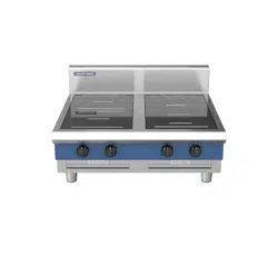
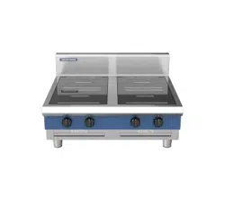
IN514 900mm Twin Dual & Quad Zone Induction Cooktop.
Safety Notices Definitions / Safety symbols and Warnings on the Appliance
Disclaimers
Correct Disposal of this Product
General
Application
Compliances
Model Numbers Covered in this Specification
Cooktops
Woks
Base options
Induction Zone Types / Glass Identification
Electrical Supply Requirements
Installation Safety - Electrical
Personal Protection
Operating Conditions
Installation Requirements
Unpacking
Location
Clearances
Assembly
Electrical Connection
Commissioning
Operation Guide
Description of Controls
Operating the Cooktops
General
After Each Use
Daily Cleaning
Weekly Cleaning
Monthly Filter Cleaning
Periodic Maintenance
Error Codes
Generator Fault Messages (E1)
2
We are confident that you will be delighted with your BLUE SEAL INDUCTION COOKTOP, and it will be-
come a most valued appliance in your commercial kitchen.
To ensure you receive the utmost benefit from your new BLUE SEAL Appliance, there are two important
things you can do.
Please read the instruction book carefully and follow the directions given. The time taken will be well
spent.
If you are unsure of any aspect of the installation, instructions or performance of your appliance,
contact your BLUE SEAL dealer promptly. In many cases a phone call could answer your question.
These instructions are only valid if the country code appears on the appliance. If the code does not
appear on the appliance, refer to the supplier of this appliance to obtain the technical instructions for
adapting the appliance to the conditions for use in that country.
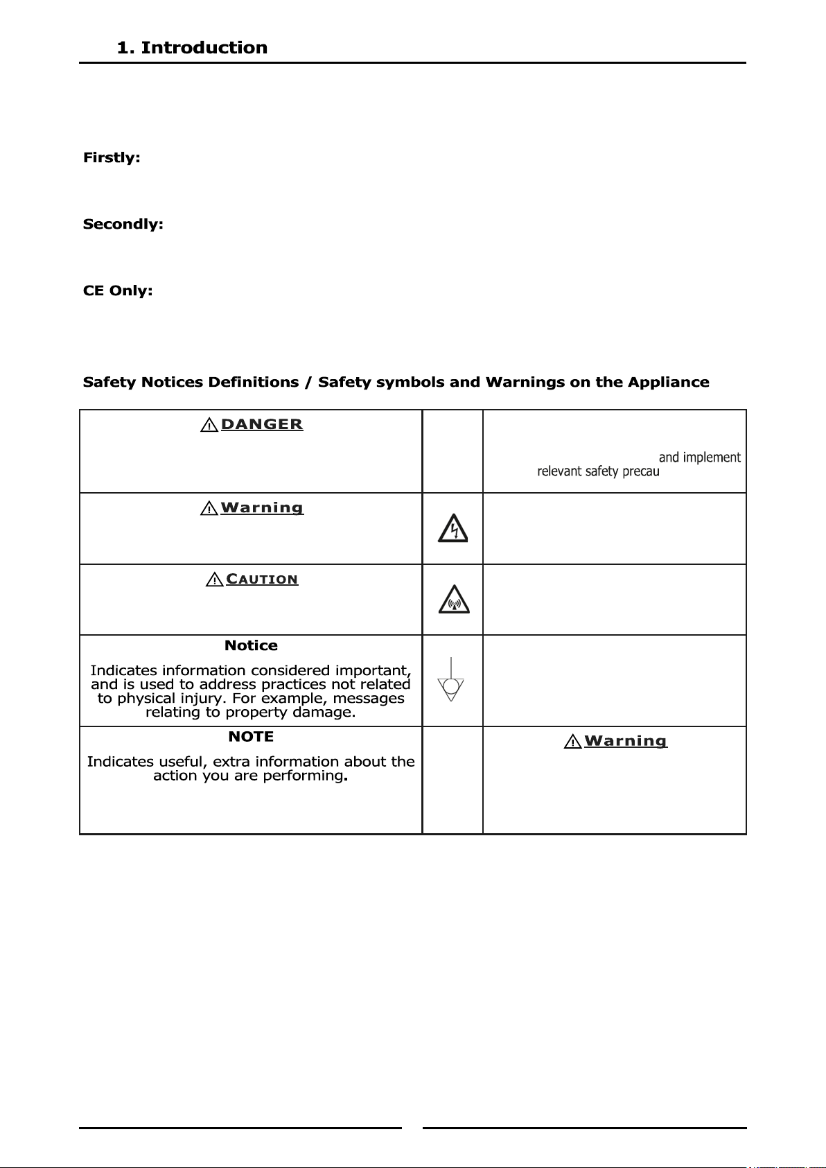
Indicates a hazardous situation that, if not avoided,
will result in death or serious injury.
This applies to the most extreme situations.
⚠
This symbol alerts you to a hazardous situa-
tion that WILL or COULD cause serious
bodily harm or death. Be alert
tions.
Indicates a hazardous situation that, if not avoided,
could result in death or serious injury.
DANGER - HIGH VOLTAGE
This dangerous voltage warning symbol
indicates a risk of electric shock and
hazards from dangerous voltage.
Indicates a hazardous situation that, if not avoided,
could result in minor or moderate injury.
Electromagnetic Field
This symbol warns against non-ionizing
electromagnetic radiation.
Equipotential bonding
This symbol marks the terminal which
has to be connected with the
equipotential bonding system.
RISK OF FIRE OR ELECTRIC SHOCK! DO
NOT OPEN!
To reduce the risk of fire or electric
shock, do not remove or open cover.
Refer servicing to qualified personnel.
3
Disregarding any safety instructions may cause harm to people, the surroundings, and the equipment. The
manufacturer and/or authorized representative are not responsible for any damages or personal injury
caused by failure to observe any safety instructions. Risks involved when disregarding safety instructions
include, but not limiting to:
Death or injury caused by electric shock.
Burn injury caused by contacting hot cooking surface, cookware, or oil and grease.
Damage to the equipment caused by using unsuitable cookware.
Do not install or operate equipment and/or accessories that have been misused, abused, neglected, dam-
aged, or altered from that of original manufactured specifications.
Contact the manufacturer if you intend to make any changes on the equipment. For safety reasons, always
use genuine parts and accessories approved by the manufacturer or authorized representative.
Refer to the warranty documents for your equipment.
Owners and operators are cautioned that maintenance and repairs must be performed by an authorized
service agent using only genuine replacement parts. The manufacturer will have no obligation with respect
to any product that has been improperly installed, adjusted, operated or not maintained in accordance
with national and local codes and/ or installation instructions provided with the product or any product that
has its serial number defaced, obliterated or removed, and/or which has been modified or repaired using
unauthorized parts or by unauthorized service agents.
Improper installation, adjustment, alteration, service, or maintenance of this appliance or installation of a
damaged appliance can result in DEATH, INJURY, EQUIPMENT DAMAGE, and void the warranty.
Do not store or use gasoline or other flammable vapors or liquids in the vicinity of this or any other
appliance. Never use flammable oil soaked cloths or combustible cleaning solutions for cleaning.
This appliance is not intended for use by persons (including children) with reduced physical, sensory or
mental capabilities, or lack of experience and knowledge, unless they have been given supervision
concerning use of the appliance by a person responsible for their safety.
Do not allow children to play with this appliance.
This product contains chemicals known to the State of California to cause cancer and/ or birth defects or
other reproductive harm. Operation, installation, and servicing of this product could expose you to airborne
particles of glass-wool or ceramic fibers, crystalline silica, and/or carbon monoxide. Inhalation of airborne
particles of glass-wool or ceramic fibers is known to the State of California to cause cancer. Inhalation of
carbon monoxide is known to the State of California to cause birth defects or other reproductive harm.
Authorized Service Representatives are obligated to follow industry standard safety procedures, including,
but not limited to, local/ national regulations for disconnection / lock out / tag out procedures for all utili-
ties including electric, gas, water and steam.
Notice
This appliance is not approved or authorized for home or residential use, but is intended for commercial
applications only. The manufacturer and/or authorized representative will not provide service, warranty,
maintenance or support of any kind other than in commercial applications.
Notice
Routine adjustments and maintenance procedures outlined in this manual are not covered by the warran-
ty.
Note
Proper installation, care and maintenance are essential for maximum performance and trouble free opera-
tion of your equipment.
4
This marking shown on the product indicates that the product should not be disposed as
household waste or regular commercial waste. Instead it shall be
handed over to the applicable collection point for the recycling of electrical and electronic
equipment. By ensuring this product is dis- posed correctly, you will help prevent
potential harm to the environment or human health, which could otherwise be caused by
inappropriate waste handling of this product.
For more detailed information regarding recycling of the product, please contact your local
city office or your waste disposal service.
NOTE: The appliance is built with common electrical, electromechanical and electronic parts.
No batteries are used.
NOTE: The owner and operator are responsible for the proper and safe disposal of the appliance.
Important
Additional Safety Notices are stated in the relevant sections throughout the manual.
5
A commercial heavy duty, high efficiency Induction Cooktop for modular kitchens, constructed with
an easy clean stainless steel external finish. It has a high option Cooktop arrangement with either a
1, 2 or 4 Induction Heat Zone. It is available on Bench legs (80mm), Legstand , Cabinet Base or
Cabinet base with door(s) industrial adjustable feet or with rear roller assemblies.
Built with a robust construction, our induction appliances are compact and powerful with the
revolutionary INDUCS RTCSmp® Technology (Realtime Temperature Control System).
The RTCSmp® Technology monitors continuously in real time, the energy supply, temperature of
the cook zone and the state of the components such as the induction coil. This monitoring system
ensures the most efficient energy transfer, as well as maximizes safety:
• Safety functions such as Pan Detection and Boil Dry Protection are therefore guaranteed.
• The appliance starts heating only when a pan is placed in the cooking zone.
• When a malfunction occurs, the integrated fault diagnostic system reports the malfunction
instantly.
Many applications throughout the day with your appliance are possible, such as cooking, warming
up, keeping warm, and roasting of food:
• Thanks to RTCSmp temperature control happens instantly.
• With inductive energy transmission, your cookware can be heated very quickly.
• High power is possible for braising application and quick sauté.
• High power also means you can heat up a bigger pot quickly.
Round Zones are most efficient for larger pots as those used in bulk cooking or
preparation.
Round = 1 pan per zone.
Full Area Zones are intended for small pots as they are used in a la carte area.
Full Area = multiple pans per zone.
Compliances
The induction technology complies to the latest norms.
Europe models
EN 55014-1
EN 55014-2
EN 60529
EN 62233 (EMC/EMV)
EN 60335-1
EN 60335-2-36
EN 61000-3-11
EN 61000-3-12
6
Cooktops
IN511R3 Induction Cooktop (450 wide) 1 x ø270 3.5kW Round Induction Zone.
IN511R5 Induction Cooktop (450 wide) 1 x ø270 5.0kW Round Induction Zone.
IN511F Induction Cooktop (450 wide) 1 x 270 x 270 5.0kW Full Area Induction Zone.
IN512R3 Induction Cooktop (450 wide) 2 x ø270 3.5kW Round Induction Zones.
IN512R5 Induction Cooktop (450 wide) 2 x ø270 5.0kW Round Induction Zones.
IN512F Induction Cooktop (450 wide) 2 x ø270 5.0kW Full Area Induction Zones.
IN514R3 Induction Cooktop (900 wide) 4 x ø270 3.5kW Round Induction Zones.
IN514R3F Induction Cooktop (900 wide) 2 x ø270 3.5kw Round Induction Zones.
2 x 270 x 270 5.0kW Full Area Induction Zones.
IN514R5 Induction Cooktop (450 wide) 4 x ø270 5.0kW Round Induction Zones.
IN514R5F Induction Cooktop (900 wide) 2 x ø270 5.0kW Round Induction Zones.
2 x 270 x 270 5.0kW Full Area Induction Zones.
IN514F Induction Cooktop (450 wide) 4 x ø270 5.0kW Full Area Induction Zones.
Base options
-B Bench Model
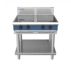
-L Legstand Model
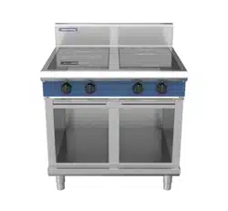
-C Cabinet Base Optional GN 1/1 racking kit.
-D Cabinet Base c/w Door(s) Optional GN 1/1 racking kit.
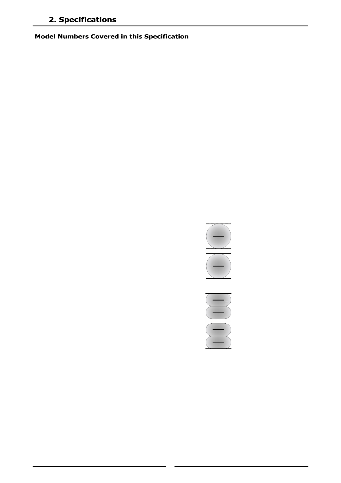
Induction Zone Types - Glass Identification
Round R3 / R5 Zone Glass Identification
2 Short line Centre of Coil / Minimum pan diameter indicator
4 Long lines Extents of Coil / Maximum pan diameter
Full Area
4 Short lines Center of Coil / Minimum pan diameter indicator
2 Long lines Extents of Coil / Extents of cooking zone.
(Shaded areas shows induction coil under glass)
7
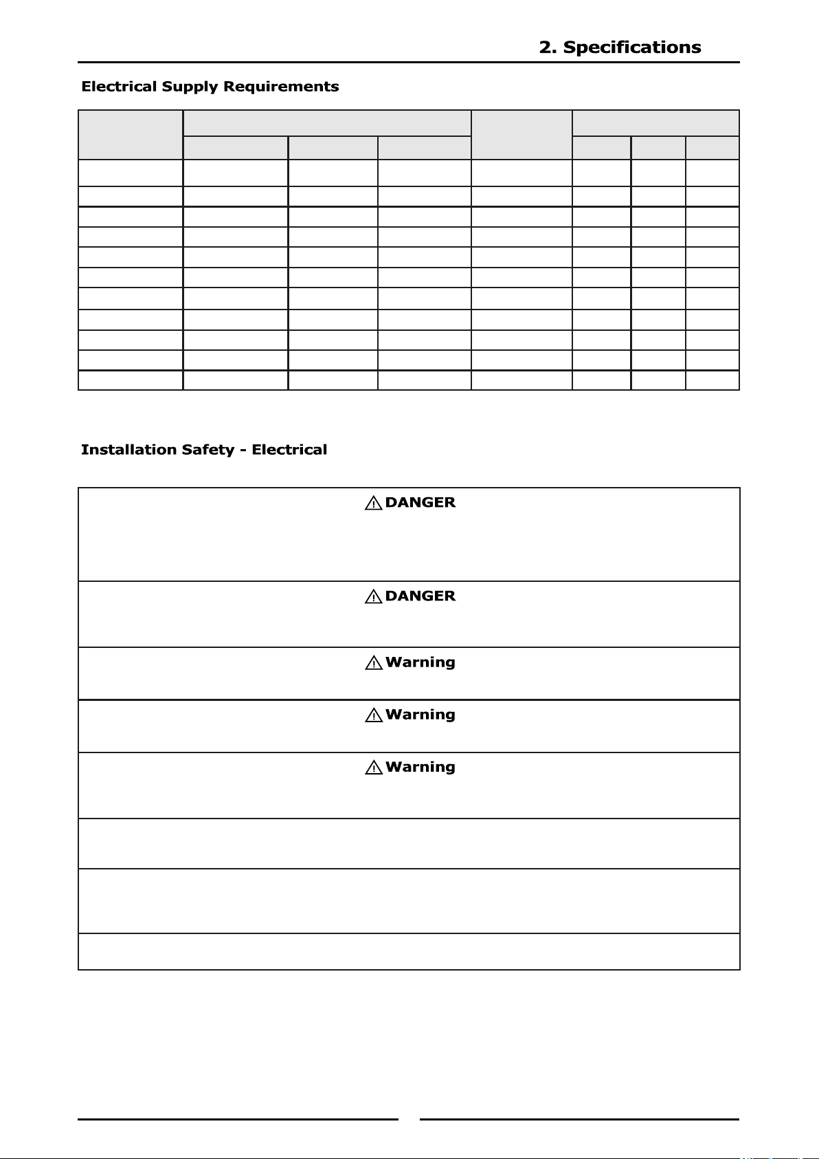
Model
Power Supply
Total Power
Input
Amps
Voltage Type Frequency
L1 L2 L3
IN511R3 230-240 Vac 1P+N+E 50 / 60 Hz 3.5 kW 15.2 n/a n/a
IN511R5 400-415 Vac 3P+E 50 / 60 Hz 5.0 kW 7.2 7.2 7.2
IN511F 400-415 Vac 3P+E 50 / 60 Hz 5.0 kW 7.2 7.2 7.2
IN512R3 400-415 Vac 3P+E 50 / 60 Hz 7.0 kW 10.2 10.2 10.2
IN512R5 400-415 Vac 3P+E 50 / 60 Hz 10 kW 14.5 14.5 14.5
IN512F 400-415 Vac 3P+E 50 / 60 Hz 10 kW 14.5 14.5 14.5
IN514R3 400-415 Vac 3P+E 50 / 60 Hz 14 kW 21 21 21
IN514R3F 400-415 Vac 3P+E 50 / 60 Hz 17 kW 24.6 24.6 24.6
IN514R5 400-415 Vac 3P+E 50 / 60 Hz 20 kW 29 29 29
IN514R5F 400-415 Vac 3P+E 50 / 60 Hz 20 kW 29 29 29
IN514F 400-415 Vac 3P+E 50 / 60 Hz 20 kW 29 29 29
Installation must be carried out by registered installation contractors only.
The contractors are responsible for interpreting all instructions correctly and performing the installation in
compliance with all applicable national and local regulations.
The warning signs and serial plates on the equipment must strictly be followed.
The device must be protected and connected with an all-pole circuit breaker which ensures complete
separation under overvoltage category III.
This equipment is intended for indoor use only. Do not install or operate this equipment in outdoor areas.
The device must be operated with an all-pole circuit breaker or dis-connector of overvoltage category III.
CE Induction Appliance only: If ground fault current protective sw itches are used, they must
be designed for a minimum fault current of 30mA, Type B or B+.
Notice
Ensure the supply voltage and the line current match the specifications given on the serial plate affixed to
the appliance. Wrong voltage will damage the appliance. A stable power supply must be provided.
Notice
Always refer to the serial plate on the appliance to verify the electrical data. When the data listed on the
serial plate is different than that listed in this manual, contact the manufacturer or the authorized
representative.
Notice
All cables must be routed, protected and tension free.
8
For the appliance to function properly, the following conditions must be maintained.
All utilities (gas, electric, water and steam) must be OFF to all equipment and locked out of operation ac-
cording to national/regional regulations, as well as company approved practices during installation,
maintenance and servicing. Always allow appliance to cool.
Use appropriate safety equipment during installation, maintenance and servicing.
To avoid cardiac pacemaker malfunction, consult your physician or pacemaker manufacturer about effects
of electromagnetic field on your pacemaker.
Replace defective power cables immediately by an authorized service agency.
Markings and warning labels mounted directly on the equipment must be observed at all times and kept in
a fully legible condition.
Risk of burns from high temperatures. You may get burnt if you touch any of the parts during operation.
Surfaces close to the cooking area including side panels may get hot enough to burn skin. Use extreme
caution to avoid coming in contact with hot surfaces or hot grease. Wear personal protective equipment.
Maximum Tolerance of the Nominal Supply Voltage +6 /-10 %
Supply frequency 50/60 Hz
Minimal Diameter of Induction Pan
12 cm
[5”]
Maximum Ambient temperature in operation
+5°C to +40°C
[+41°F to +104°F]
Maximum Relative Humidity in operation 30% to 90%
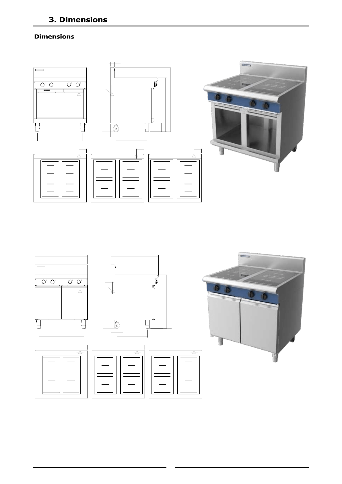
9
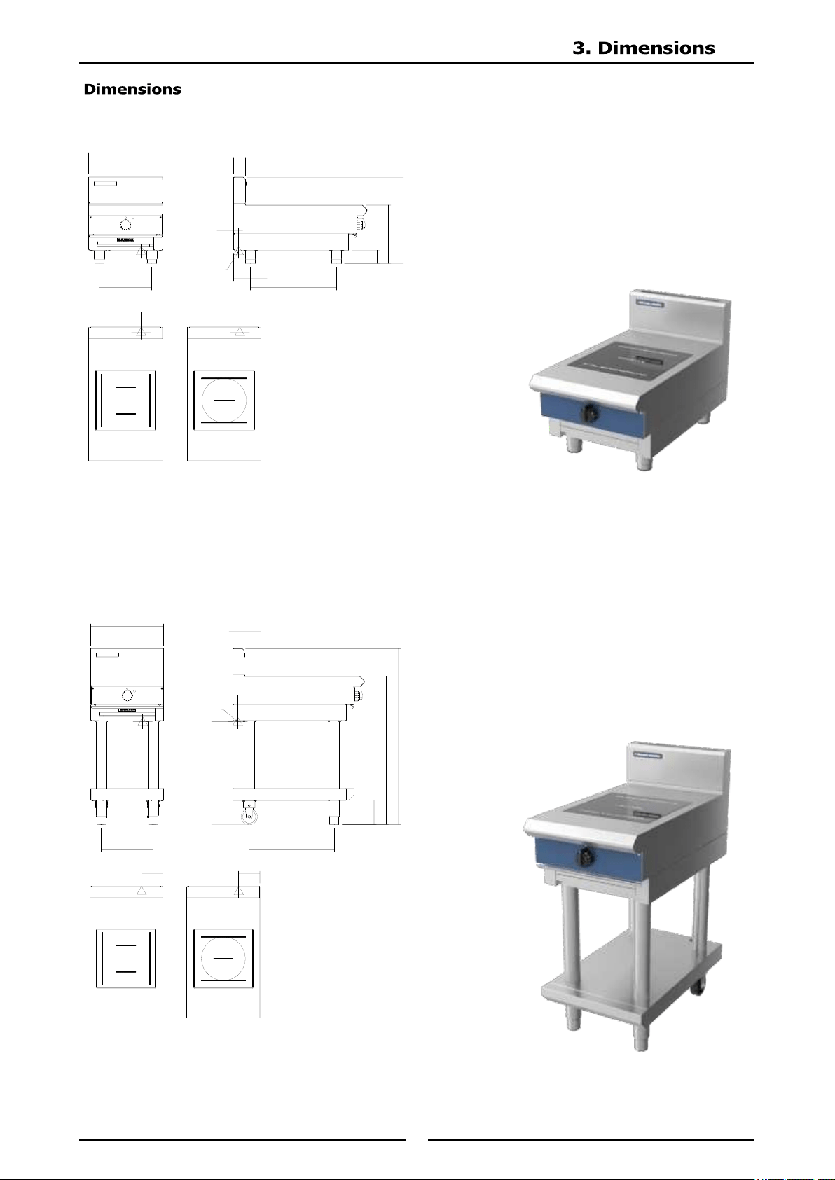
IN511*-B
IN511*-L
ELECTRICAL
ENTRY
450
70
525
85
355
319
100
525
30
130
IN511F
IN511R
130
ELECTRICAL
ENTRY
450
915
1085
150
319
100
525
635
30
70
130
IN511F IN511R
130
10
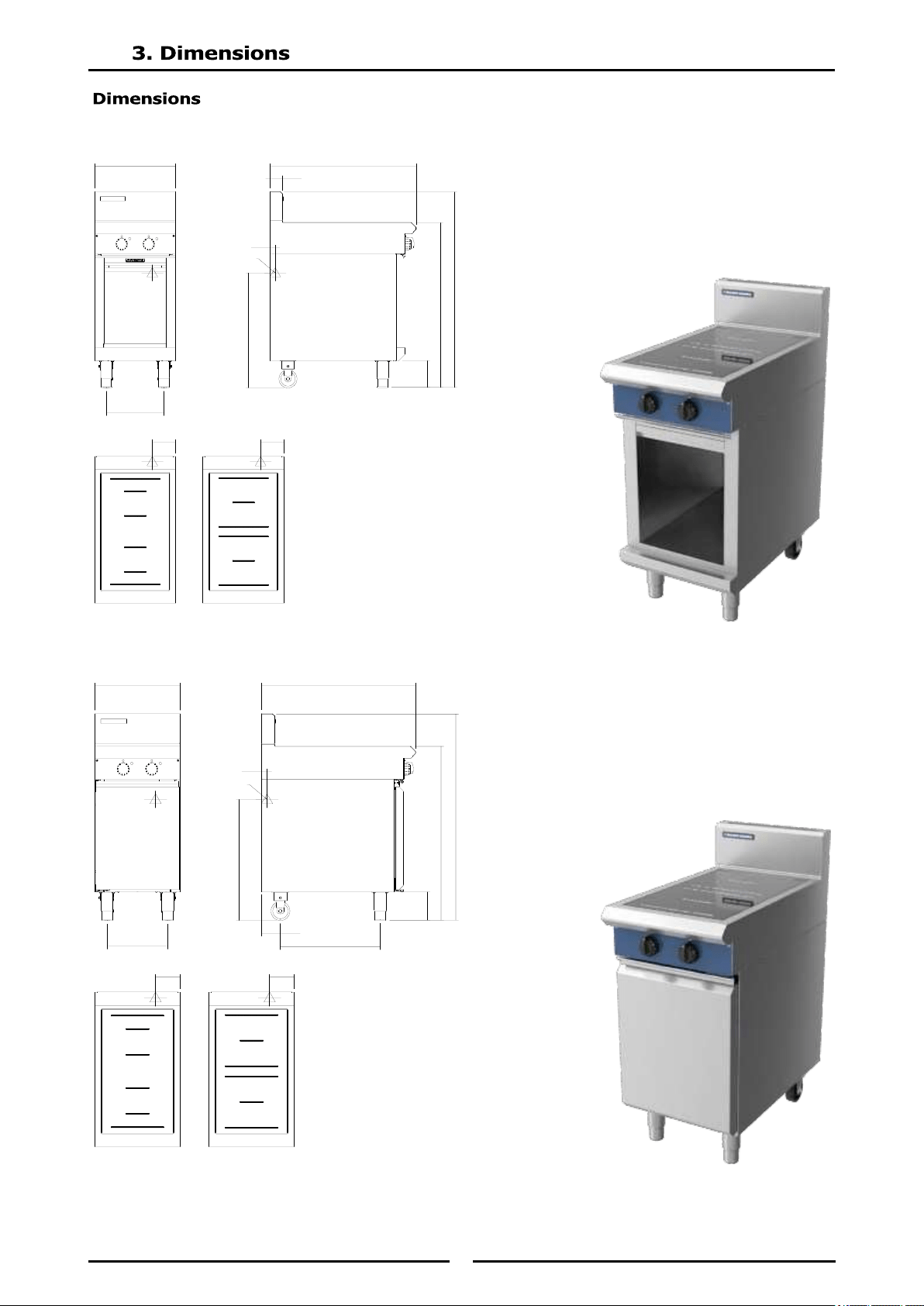
IN512*-C
IN512*-D
450
319
ELECTRICAL
ENTRY
30
635
812
70
148
913
1083
130
IN512F
IN512R
130
450
319
100
525
635
30
812
148
913
1083
ELECTRICAL
ENTRY
130
IN512F IN512R
130
11
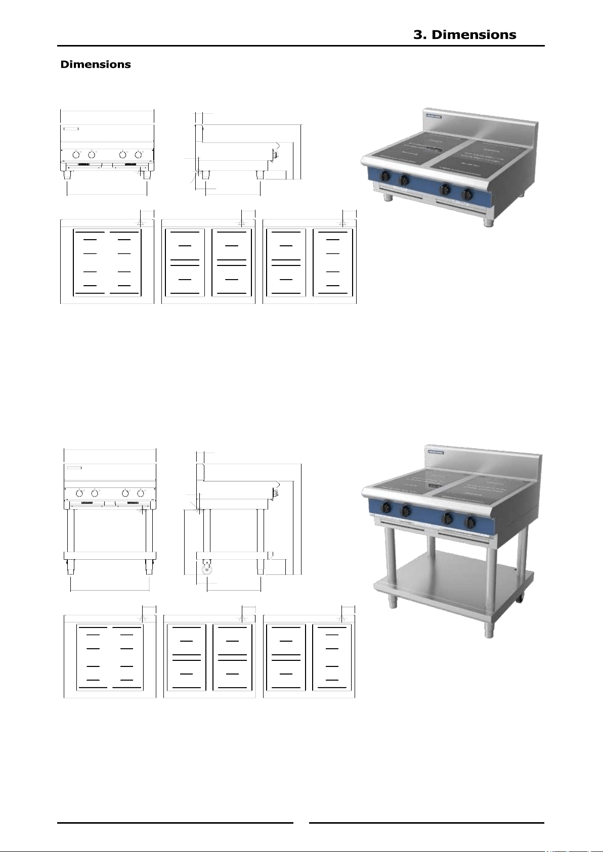
IN514*-B
IN514*-L
ELECTRICAL
ENTRY
70
525
85
355
100
525
30
900
769
130
IN514F IN514R
130
IN514RF
130
ELECTRICAL
ENTRY
915
1085
150
100
525
635
30
70
900
769
130
IN514F
IN514R
130
IN514RF
130
12
IN514*-C
IN514*-D
ELECTRICAL
ENTRY
30
635
70
100
525
148
913
1083
769
130
IN514F
IN514R
130
IN514RF
130
ELECTRICAL
ENTRY
635
30
812
100
525
148
913
1083
900
769
130
IN514F
IN514R
130
IN514RF
130
13
NOTE:
It is most important that this Induction Cooktop is installed correctly and that operation is
correct before use. Installation shall comply with local electrical and health and safety
requirements.
Blue Seal Induction Cooktops are designed to provide years of satisfactory service, and correct installation
is essential to achieve the best performance, efficiency and trouble-free operation.
This appliance must be installed in accordance with National installation codes and in addition, in
accordance with relevant National / Local codes covering electrical and fire safety.
Australia / New Zealand AS/NZS 3000 - Wiring Rules.
United Kingdom: BS 7671 - Requirements for Electrical Installations.
Installations must be carried out by qualified persons only. Failure to install equipment to the
relevant codes and manufacturer’s specifications shown in this section will void the
warranty.
Components having adjustments protected (e.g. paint sealed) by manufacturer, are only
to be adjusted by an authorised service agent. They are not to be adjusted by the installation
person.
Remove all packaging and transit protection from the appliance including all protective plastic coating
from the exterior stainless steel panels.
Check equipment and parts for damage. Report any damage immediately to the carrier and
distributor.
Report any deficiencies to the distributor who supplied the appliance.
Check that the available electrical supply is correct to that shown on the Rating Plate attached to the
underside of the R/H side, front Induction Cooktop lower trim.
1. Installation must include adequate clearance and ventilation.
2. Position the appliance in its approximate working position.
3. The legs must always be fitted. Ensure that the legs are securely attached.
Clearances
NOTE: Only non-combustible materials can be used in close proximity to this appliance.
Left / Right Hand Side 50mm 0mm
Rear 50mm 0mm
14
Bench Mount (B) Models
1. Check that all the feet are fitted and adjust to make the hob steady and level.
Optional Accessories (Refer to Replacement Parts List)
Plinth Kit. For installation details, refer to the instructions supplied with each kit.
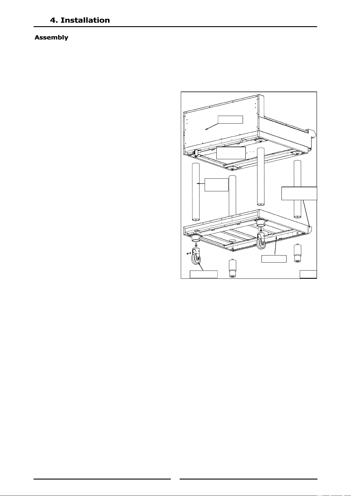
Leg Stand (LS) Models Only
1. Lower the appliance onto its rear face.
2. Attach the four Cooktop legs to the leg
mount points on the underside of the
Cooktop unit.
3. Secure each leg hand tight.
4. Align the 4 round holes in the corners of
the base tray with the 4 Cooktop legs
already fitted. (Ensure that the base
tray is orientated with the sloping edge
of the base tray facing the front of the
appliance).
5. Slot the base tray onto the 4 Cooktop
legs and push fully home.
6. Secure the base tray to the front cooktop
legs by screwing the adjustable feet
supplied, into the base of the front
cooktop legs. Secure each adjustable
foot, hand tight.
7. Fit the rear rollers to the rear leg ring
plates and secure using the locating bolts
supplied and tighten bolts using a 10mm
spanner.
8. Lift the Cooktop back onto its legs.
NOTE: This appliance is fitted with adjustable
feet / rear rollers to enable the appliance to
be positioned securely and level. This
should be carried out on completion of the
electrical connection. Refer to the
‘Electrical Connection’ section.
All Other Models
All other models come pre-assembled.
Fig 1
Sloping Edge
of Base Tray
Rear Roller
Base Tray
Cooktop
Legs
Leg Mount
Points
Cooktop
15
Each appliance should be connected to an adequately protected power supply and isolation switch mounted
adjacent to, but not behind the appliance. This switch must be clearly marked and readily accessible in
case of fire.
1. Check that the electricity supply is correct as shown on the Rating Plate. Refer to the section 3
(Dimensions) for rating plate locations for the different model types.
2. The supply terminal connections are located at the rear of the the appliance. Refer to ‘Electrical
Connections’ in the section 2 (Specifications) of the manual.
3. Bring the supply cable up through the compression type gland provided on the rear of the main
electrical switchgear panel.
4. Connect the mains supply to L1, L2 and L3 terminal connections as required. Refer to the Electrical
Supply Requirements in section 2 (Specifications).
5. Connect earth conductors to earth terminal.
6. For all connections ensure that conductors are secure and appropriately terminated.
7. Tighten the cable gland to secure against tension on the cable.
8. Correctly locate the appliance into its final operating position and using a spirit level, adjust the legs
so that the appliance is level and at the correct height.
9. Connect the power supply to the appliance.
10. Check that the electrical supply is as shown in section 2 (Specifications).
This appliance must be earthed. If the supply cord is damaged, it must be replaced by a suitably qualified
person in order to avoid a hazard.
Notice
ALL ELECTRICAL CONNECTIONS MUST ONLY BE CARRIED OUT BY A QUALIFIED SERVICE PERSON.
Notice
This appliance must be earthed.
Fixed wiring installations must incorporate an all-pole disconnection switch.
16
1. Remove all objects from the glass top and examine the glass.
2. Connect the appliance to power supply.
Function Test
Testing procedure:
1. Examine the cookware for induction cooking:
Pans must be induction ready. See details in section 5 (Operation).
Minimum pan size: Pan must have bottom diameter larger than 12cm [5”].
Otherwise, the pan will not be heated. This is a safety feature.
The sensors does not detect pan smaller than this minimum size.
2. For each cooking zone turn the control to any power level setting.
3. Ensure the indicator (green) is flashing at a steady rate. This indicates the pan detection
sensors are operational.
4. Put some water in an induction pan and place it in the center of the cooking zone.
The indicator (green) should now show ia steady state. This indicates power is being
transferred to the pan.
5. Remove the pan from the cooking zone and check the indicator returns to flashing at a steady
rate.
6. Turn cooking zone off.
7. Repeat steps 2 - 6 for all cooking zones.
To test the efficiency of a pan for induction cooking, refer to section 7 (Troubleshooting).
If the appliance does not function as expected despite using quality induction pans, refer to section 7
(Troubleshooting).
If the unit does not operate correctly, remove from the electrical supply and contact a qualified
service person. The supplier of the unit will be able to recommend a suitable person.
This manual must be kept by the owner for future reference and as a record of Date of Purchase,
Date of Installation and Serial Number of Unit recorded and kept w ith this manual.
These details can be found on the Rating Plate attached to the inner R/H side panel.
Refer to the section 3 (Dimensions) for rating plate location.
⚠
Read and understand all installation safety instructions regarding Personal
Protection.
Observe also ALL operation safety requirements in section 3 (Operation).
⚠
Read and understand all installation safety instructions regarding Personal
Protection.
Observe also ALL operation safety requirements in section 5 (Operation).
⚠
Caution
Do not continue if the glass top is cracked, chipped or damaged in any other
way.
Contact an authorized service agency for assistance
17
The on-site supervisor is responsible to train operators for operating, maintaining and ensuring that
operators are made aware of the inherent dangers of operating this equipment.
Risk of fire/shock/equipment failure. All minimum clearances must be maintained. Do not obstruct vents or
openings.
This equipment is intended for indoor use only. Do not install or operate this equipment in outdoor areas.
Notice
The reliability of the appliance can only be guaranteed when it is used properly. The appliance must always
be operated within the limits and/or the operating conditions provided in this manual.
Notice
Avoid dropping any hard objects onto the equipment. Damages to the heating surface will shortened the
life cycle of the equipment or incur high service costs.
Notice – Models with Glass-Top
Use Only Induction Suitable Cookware
Use only induction suitable cookware with proper sizes and made of proper material. The induction suitable
cookware must be in good condition without any uneven, arched or partially detached bottoms.
Using unsuitable cookware can cause the appliance to fail prematurely, void your warranty, and incur high
service costs.
18
Notice
Induction appliances are more powerful, heat up pans quicker, and cook food faster than conventional
cooking equipment. Your induction appliance needs to be operated and looked after in a different way than
other conventional equipment.
Do not operate the equipment without reading this manual and understanding all safety requirements.
If any part of the appliance is cracked or broken, turn off the appliance and immediately disconnect the
appliance from supply.
Only if it is possible and safe, disconnect the equipment from main power supply. Do not touch any parts
inside the appliance.
Disconnect electric power at the main power disconnector for all equipment being serviced.
Failure to disconnect the power at the main power supply could result in serious injury or death.
The knob DOES NOT disconnect incoming power.
Contact an authorized service agency for assistance.
To avoid cardiac pacemaker malfunction, consult your physician or pacemaker manufacturer about effects
of electromagnetic field on your pacemaker
Never stand, sit, or lean on the equipment!
They are not designed to hold the weight of an adult, and may collapse or tip if misused in this manner.
Short Cook Time
Induction appliances cook food faster than conventional cooking equipment. To avoid overheating and
burning, check the cooking process frequently. Never leave the appliance unattended during operation.
Metallic objects are heated up very quicky when placed on the induction cook zone during operation. To
avoid injury,
DO NOT place any objects such as closed cans, aluminum objects (aluminum foils), cutlery, jewelry, or
watches on the appliance.
DO NOT place any object such as paper, card- board, or cloth on the cooking surface, because this creates
a fire hazard.
DO NOT place credit cards, phone cards, tapes, or any objects that are sensitive to magnetism on the ap-
pliance.
DO NOT use the appliance for storage.
DO NOT place any paper products, cooking utensils, cutlery, plastic vessels or food on the appliance.
DO NOT place metallic objects such as kitchen utensils, cutlery etc. on the hob surface within the cooking
zones since they could get hot.
Aluminum foil must not be used with induction appliances! Aluminum foil may ignite and cause a fire!
Notice
Do not use the cooktop for food preparation such as cutting and chopping.
Risk of burns from high temperatures. You may get burnt if you touch any of the parts during operation.
Surfaces close to the cook- ing area including side panels may get hot enough to burn skin. Use extreme
caution to avoid coming in contact with hot surfaces or hot grease. Wear personal protective equipment.
Take care when operating the appliance, as rings, watches and similar objects worn by the user could get
hot when in close proximity to the hob surface.
During operation, it is possible that the floor around the unit become slippery. Wear suitable footwear and
clean the floor if necessary.
19
Blue Seal appliances have been designed to provide simplicity of operation.
Improper operation is therefore almost impossible, however bad operational practices can reduce the life of
the appliance and produce a poor quality product. To use this appliance correctly please read the following
sections carefully.
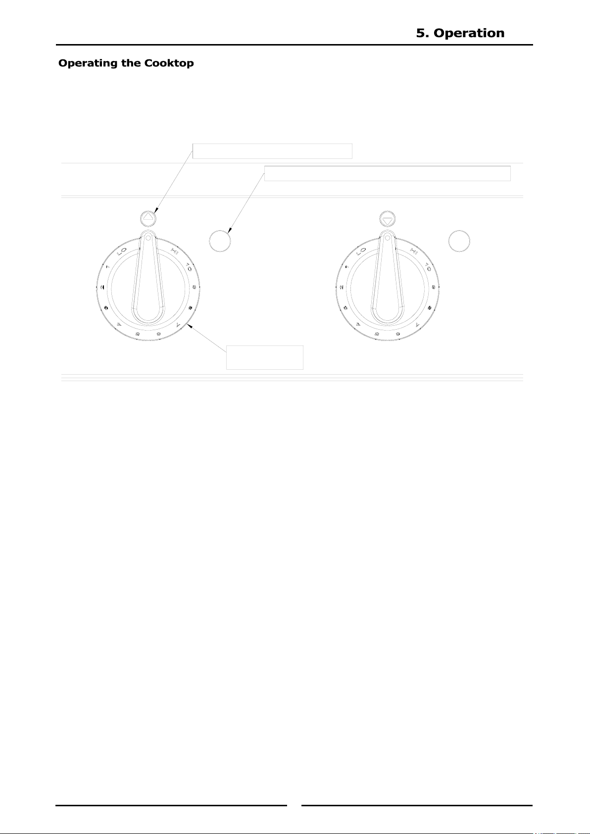
Description of Controls
HI / LO Power Control Knob
Used to select the hob required and to adjust the temperature setting for individual cooking zones.
Pan Detection / Power / Fault Indicator (Green)
Illuminates and remains ‘On’ when a selected cooking zone is turned ‘On’ and has a pan on the cooking
zone.
If the hob is turned ‘On’ without a pan on the cooking zone, the lamp will commence flashing at a steady
rate until a pan is placed on the selected cooking zone.
Also used as the ‘Fault Indicator’ to display Generator Faults, refer to ‘Error Code Pattern’ in the ‘Fault
Finding’ section.
HI - LO POWER
CONTROL KNOB
PAN DETECTION / POWER / FAULT INDICATOR (GREEN)
COOKING ZONE INDICATOR (REAR)
20
Blue Seal appliances have been designed to provide simplicity of operation.
Improper operation is therefore almost impossible, however bad operational practices can reduce the life of
the appliance and produce a poor quality product. To use this appliance correctly please read the following
sections carefully.
The controls for the cooking zones may be set at any position between ‘High’ and ‘Low’ to provide the
desired level of heating. An individual green neon for each hob, will glow when the hob is ‘On’ with a pan
present and extinguish when the hob is turned ‘Off’.
Start cooking at the highest setting, and change to a lower setting when desired temperature is reached.
1. Turn power ‘On’ at the mains power supply.
2. Place cooking pan onto the cooking zone be used, ensuring that there is liquid in the pan.
3. Turn the control knob to the desired temperature. The ‘Green’ indicator lamp will illuminate and stay
‘On’.
4. On completion of cooking, turn ‘Off’ the control knob and remove the pan, the green indicator light
will extinguish.
INDUCTION HEAT SOURCE - CARE MUST BE TAKEN TO ENSURE THAT THE SPLASHBACK AND SURROUNDING
AREAS ARE KEPT FREE OF METALLIC OBJECTS.
IF THE CONTROL KNOB IS TURNED ‘ON’ WITHOUT A PAN IN THE COOKING ZONE, THE GREEN INDICATOR LAMP
WILL COMMENCE FLASHING AT A STEADY RATE UNTIL A PAN IS PLACED IN THE COOKING ZONE.
DO NOT HEAT EMPTY PANS WITHOUT SUPERVISION. ALWAYS PLACE PANS IN THE CENTRE OF A COOKING
ZONE. PANS SHOULD NOT BE HEATED UP TO MORE THAN 300˚C (570˚F).
IF A FAULT HAS BEEN DETECTED. THE GREEN INDICATOR LIGHT WILL COMMENCE FLASHING. REFER TO ‘ERROR
CODE PATTERN’ IN THE SECTION 7 (TROUBLESHOOTING).
DO NOT USE THE APPLIANCE UNTIL THE FAULT IS RECTIFIED.
21
Follow these simple rule to ensure reliable and repeatable performance of your induction equipment.
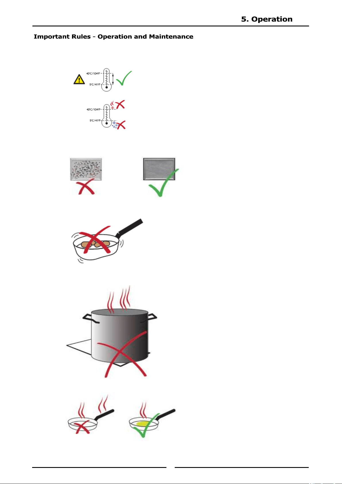
1. Keep the kitchen temperature below 40°C [104°C].
2. Clean the intake filter at least once a week or as often as required.
3. Do not use dented pans because it will cause damage to the electronics.
4. Use only pans that fit the glass markings. Do not use oversize pans.
5. Never pre-heat the pan. Place the pan on the cooking zone when you are ready to cook.
22
Follow these simple rule to ensure reliable and repeatable performance of your induction equipment.
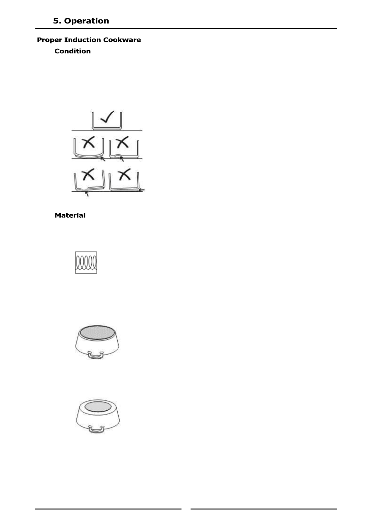
Pans with layer separation (outward and inward bubbles), arching or partially detached
bottoms must be replaced.
When these pans are used, the sensors under the glass-top cannot detect the temperature
correctly. These pans will overheat the sensors and eventually will damage the sensors and
the generator. The image below, shows examples of good and bad pans in cross section.
Use cookware made of conductive and magnetic materials. If the pan bottom attracts a
magnet the pan is suitable for induction cooking. Look for cookware that is labeled “Suitable
for Induction” or marked with an induction compatible symbol.
Do not use pans made of aluminum, copper, glass or ceramics.
Note - Steel inserts on bottom:
Cookware base inserted with areas of aluminum reduces the magnetic area for
induction cooking. The appliance may supply less energy to the cookware or have
difficulties in detecting the pan.
Note - Non-magnetic cookware with a small magnetic base.
The exposed non-magnetic metal on the base may affect the induction field and
subsequently, less energy may be supplied to the cookware.
23
To test the efficiency of a pan for induction cooking, perform a boil test. See instructions in Section 7
(Troubleshooting).
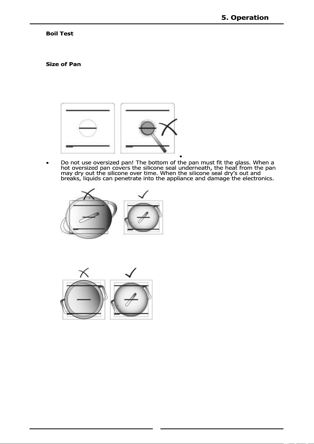
Minimum Size: The bottom of pan must have a minimum diameter of 12cm [5’] (image below,
shows minimum size against glass marking), Otherwise, the pan will not be heated. This is a
safety feature such that the unit does nto detect and heat p small metal objects, such as
jewelry. Note: For personal safety, never place any small metallic object on a cook zone.
Pan must fit the glass! The best pan to use is the one with a bottom that fits the coil.
24
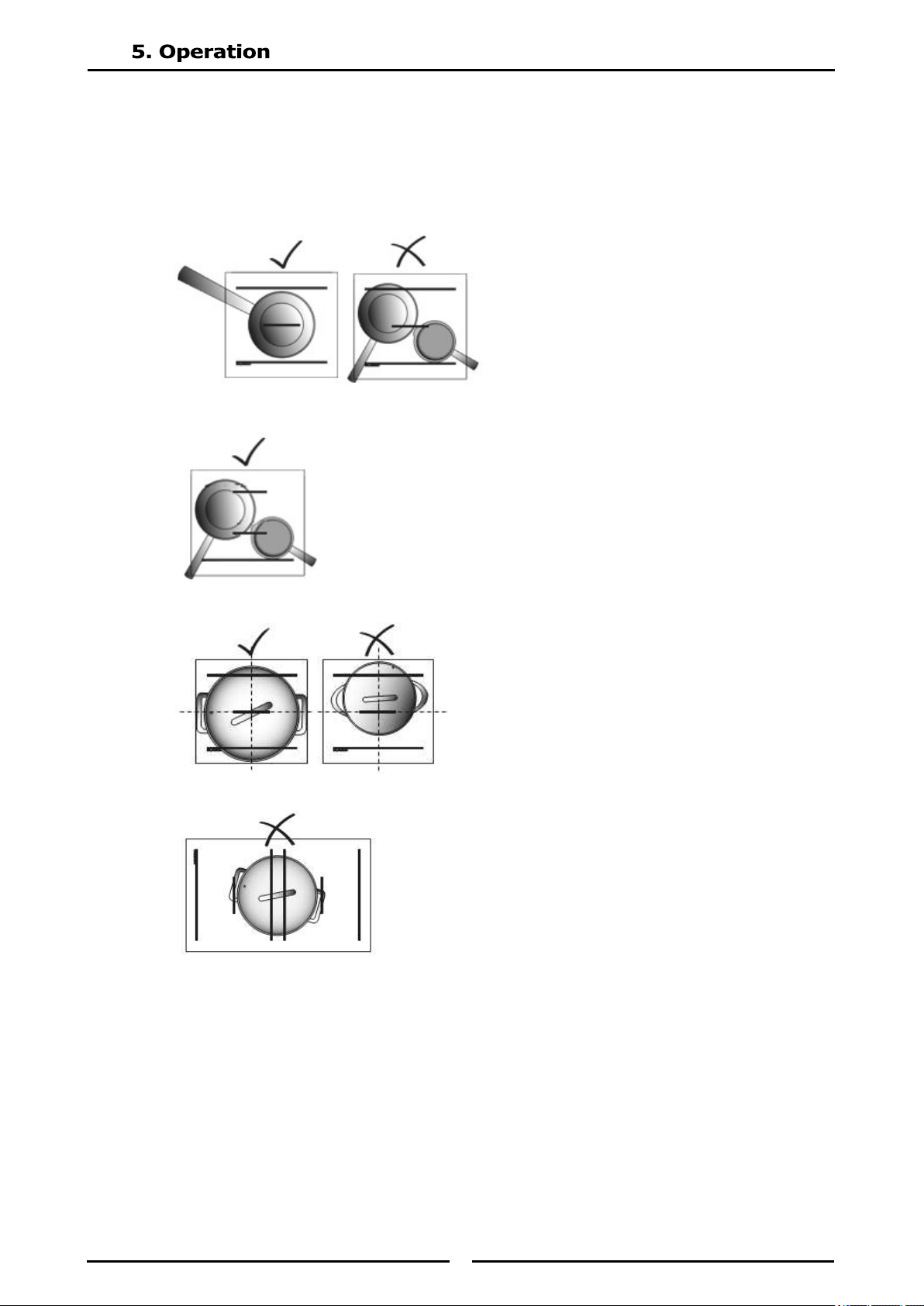
Placing Pan on a Cooking Zone
Each cook zone of our appliances is equipped with the latest RTCSmp® sensors. These sensors
monitor temperature and cookware continuously in real time.
To obtain optimal results from the sensors, you must always place pan in the center of the cook
zone. Otherwise, the bottom of the pan is heated unequally and the food inside the pan may burn.
For Round cooking zones place one pan per cook zone.
For Full Area cooking zones you can use one pan or multiple pans per cook zone.
Always place pan in the center of a cook zone.
Pan must not cover more than one cook zone on dual, twin dual or quad units.
25
MAINTENANCE SAFETY - DISCLAIMER
MAINTENANCE SAFETY - CLEANING
It is the responsibility of the equipment owner to perform a Personal Protective Equipment Hazard Assess-
ment to ensure adequate protection during maintenance procedures.
A good maintenance of the appliance requires regular cleaning, care and servicing. The site supervisor and
the operator must ensure all components relevant to safety are in perfect working order at all times.
Notice
Cleaning tools and supplies are not pro-vided.
Do not open the appliance. Maintenance and servicing work other than cleaning as described in this
manual must be done by an authorized service personnel.
If any part of the appliance is cracked or broken, turn off the appliance and immediately disconnect the
appliance from supply. Only if it is possible and safe, disconnect the equipment from main power supply.
Do not touch any parts inside the appliance.
Disconnect electric power at the main power for all equipment being serviced.
Failure to disconnect the power at the main power supply could result in serious injury or death.
The power switch DOES NOT disconnect all incoming power.
Contact an authorized service agency for assistance.
Never use a high-pressure water jet for cleaning or hose down or flood interior or exterior of the equip-
ment with water. Ensure that no liquid can enter into the equipment.
Allow heated equipment / glass surface to cool down before attempting to clean, service or move.
When cleaning the exterior, care should be taken to avoid front power switch and the electrical cords.
Keep water and cleaning solutions away from these parts.
Do not use caustic cleaners on any part of the equipment. Use mild, non abrasive soaps or detergents,
applied with a sponge or soft cloth.
Ensure to remove all residues of cleaning agents from the cooking surfaces. Use a clean moist cloth to
wipe off any surfaces.
Using commercial cleaning fluids or chemicals: Read the directions for use and precautionary statements
before use. Pay attention to the concentration of cleaner and the length of time the cleaner remains on the
food contact surfaces or equipment surfaces.
Notice
Inspect and Clean Fresh Air Intake Filter. A dirty, blocked air intake filter blocks the air vent and can
cause damages to the electronic components. Inspect, clean or replace the air intake filters at least once a
week or as often as necessary.
Inspect Silicone Seal
When the silicone seal is broken, water penetration could cause the appliance to fail, and any malfunction
could cause personal harm
26
MAINTENANCE SAFETY - PERSONAL PROTECTION
All utilities (gas, electric, water and steam) must be OFF to all equipment and locked out of operation ac-
cording to national/regional regulations, as well as company approved practices during installation, mainte-
nance and servicing. Always allow appliance to cool.
Use appropriate safety equipment during installation, maintenance and servicing.
To avoid cardiac pacemaker malfunction, consult your physician or pacemaker manufacturer about effects
of electromagnetic field on your pacemaker.
Replace defective power cables immediately by an authorized service agency.
Markings and warning labels mounted directly on the equipment must be observed at all times and kept in
a fully legible condition.
Risk of burns from high temperatures. You may get burnt if you touch any of the parts during operation.
Surfaces close to the cooking area including side panels may get hot enough to burn skin. Use extreme
caution to avoid coming in contact with hot surfaces or hot grease. Wear personal protective equipment.
During operation or cleaning, it is possible for the floor to become slippery around the unit. Wear suitable
footwear and clean the floor when needed.
27
Daily Cleaning and Maintenance
Clean the surface with a mild detergent and/or a food safe liquid cleaner which not penetrate the
silicone seal around the glass.
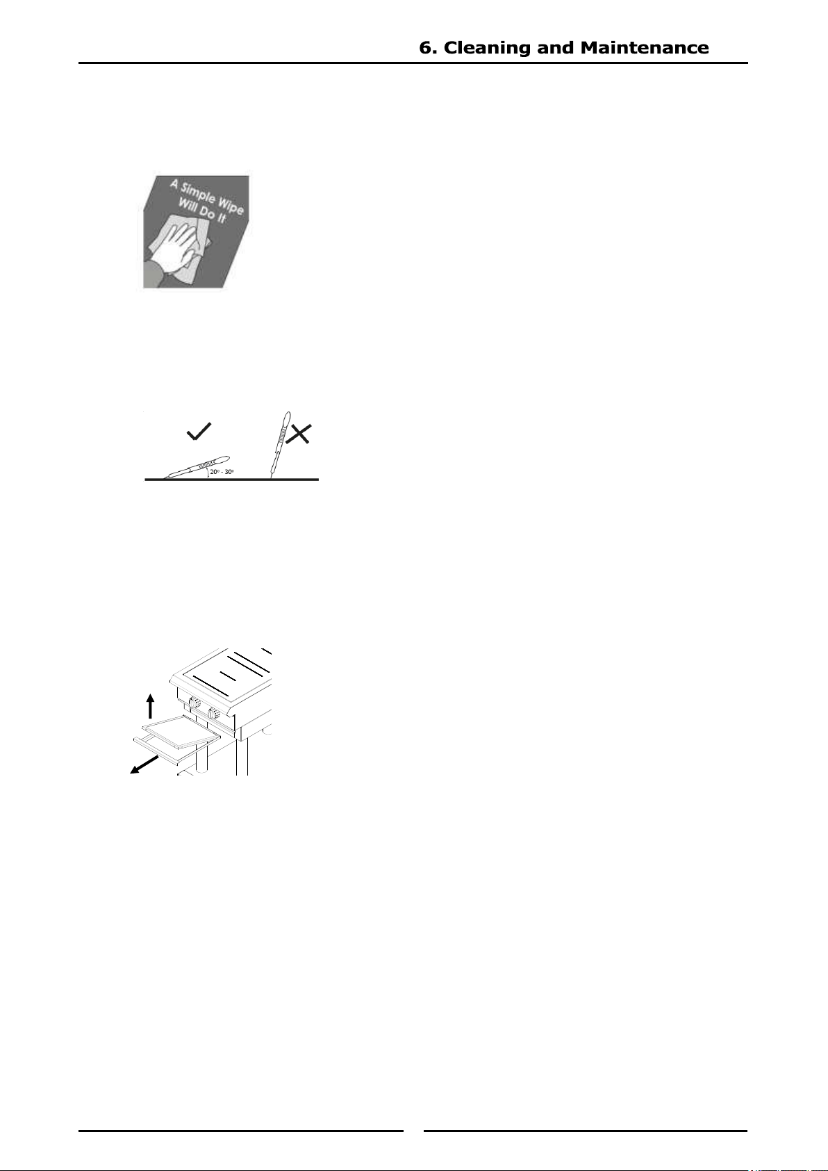
GLASS CLEANING
NOTE: The cleaning of Ceran® glass is identical to cleaning other similar glass surfaces.
You may use any regular glass cleaning products available from a hardware store.
You may use a razor blade scraper or a non scratching sponge to remove tough residues. When
scraping, place your razor blade scraper at an angle of about 20° to 30° from the glass. Then wipe
clean the glass with a cleaning product.
VISUAL INSPECTION OF SILICONE SEAL
Inspect the silicone seal around the glass perimeter. Call for service immediately if you notice:
Cracks on the silicone seal.
The silicone seal comes away from the glass/ housing or moves when you press down on the
seal.
Weekly Cleaning and Maintenance
Remove and clean air filter.
1. Pull the filter tray forward and remove the filter from the support tray.
2. Wash with warm soapy water or in dishwasher, rinse and allow to dry thoroughly
3. Re-fit filter into the filter tray and return to unit.
Note: Do not operate unit without air filter fitted.
Yearly Maintenance
Best Practice: Have the induction appliance ex amined once a year by an authorized
technician.
General Maintenance Tips:
Inspect all induction cookware to ensure proper condition.
Have an authorized technician to inspect and ensure that:
All ventilation fans are working properly.
No grease built-up around the equipment and air filter.
The silicone joints of the ceramic glass are in good condition.
28
DANGEROUS ELECTRICAL VOLTAGE
Common Problems
One or more of the following conditions may affect the function or cause the induction equipment to fail:
Using unsuitable cookware such as non induction pans, oversized pans, or damaged pans.
High ambient temperature.
Inadequate ventilation causing hot air to re-enter through the air intake slots.
Dirty air intake filter.
Empty pan is left on the hob when the appliance is ON.
Symptoms
When a malfunction occurs, the appliance may be in one of the following states:
The appliance switches off immediately.
The appliance continues to operate in a power reduction mode.
The appliance continues to operate normally.
NOTE:
The cooling fan starts when the ambient temperature in the control area exceeds 55ºC [130ºF].
At heat sink temperature higher than 70ºC [160ºF], the controller automatically reduces power to keep the
appliance in normal operating conditions.
If any part of the appliance is cracked or broken, turn off directly the appliance and Immediately disconect
the appliance from supply. Only if it is possible and safe, disconnect the equipment from main power sup-
ply. Do not touch any parts inside the appliance.
Disconnect electric power at the main power for all equipment being serviced.
Failure to disconnect the power at the main power supply could result in serious injury or death.
The power switch DOES NOT disconnect all incoming power.
Contact an authorized service agency for assistance.
Do not open the appliance. Maintenance and servicing work other than cleaning as described in this manu-
al must be done by an authorized service personnel.
Markings and warning labels mounted directly on the equipment must be observed at all times and kept in
a fully legible condition.
Notice
If a problem arises during operation of your induction appliance, follow the Troubleshooting Charts before
calling service. Routine adjustments and maintenance procedures are not covered by the warranty.
29
Boil Test
To test the quality of a pan for induction cooking, perform a boil test.
(Test for 3.5kW or 5.0kW Induction Coil)
Perform a boil test to verify the performance of a pan for induction cooking.
Add one litre of cold water into the pan (op-timal when use pan with bottom diameter of 24cm) and
bring it to boil.
Compare the total boil time to the guideline below:
3.5kW Coil, approx. 140 seconds
5.0kW Coil, approx. 85 seconds
If time to boil exceeds the above guideline, then the pan is not suitable for achieving optimal
efficiency.
Please contact your supplier to purchase suitable induction pans.
If the induction appliance does not function as expected despite using quality induction pans, refer to
the troubleshooting charts.
Avoiding dangers in case of accidents or malfunctions
To avoid hazards in the event of a malfunction or accident related to the device, proceed as follows.
1. Disconnect the power supply from the circuit breaker provided for the device.
2. Disconnect the mains plug of the affected device to prevent it from being switched on again.
If the plug is not safely accessible, the device must be switched off at the main circuit breaker.
30
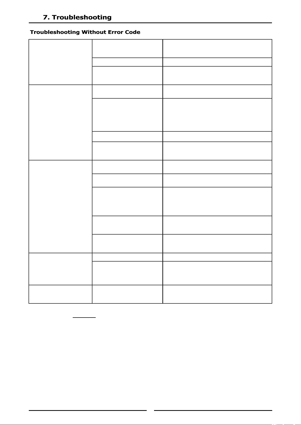
(1) ⚠DANGER If the plug is not safely accessible, the device must be sw itched off
at the main circuit breaker.
Pan does not heat up on
cooking zone.
Indicator is not illuminated
No power supply.
Check incoming power supply (Example, power
cable plugged into the wall socket). Check
kitchen main fuse box.
Unit is turned off. Turn control knob to an ON position.
Defective unit
Only if possible and safe, disconnect the appli-
ance from the power supply. Contact an au-
thorized service agency. (1)
Pan does not heat up and
LED indicator flashes at
steady rate.
Pan is too small.
Use a suitable pan with bottom diameter larger
than 12cm[5”].
Pan is not placed in the cen-
ter of cooking zone; pan is
not detected by sensor.
(2)
Move the pan to the center of the cooking
zone.
Unsuitable pan. Select only induction ready cookware.
Defective unit.
Only if possible and safe, disconnect the appli-
ance from the power supply. Contact an au-
thorized service agency. (1)
Poor heating, LED
indicator is steady ON
Air cooling system is obstruct-
ed.
Verify that air vents are not obstructed. Ensure
the fresh air filter is clean.
Unsuitable pan.
Select various induction ready cookware for
induction cooking. Then compare the results.
Ambient temperature is too
high.
The cooling system is not
able to keep the appliance in
normal operating conditions.
Verify that no hot air is taken in by the fan.
Reduce the ambient temperature. The intake
air temperature must be lower than 40°C
[104°F].
One phase is missing.
Check incoming power supply (Example, power
cable plugged into the wall socket). Check
kitchen main fuse box.
Defective unit.
Only if possible and safe, disconnect the appli-
ance from the power supply.
Contact an authorized service agency. (1)
Appliance does not react
to control knob positions
Unit is turned off. Turn control knob to an ON-position.
Defective control knob.
Only if possible and safe, disconnect the appli-
ance from the
power supply. Contact an authorized service
agency. (1)
Small metallic objects
(e.g. spoon) are heated
up in the cook zone.
Pan detection function is de-
fective.
Only if possible and safe, disconnect the appli-
ance from the power supply. Contact an au-
thorized service agency. (1)
31
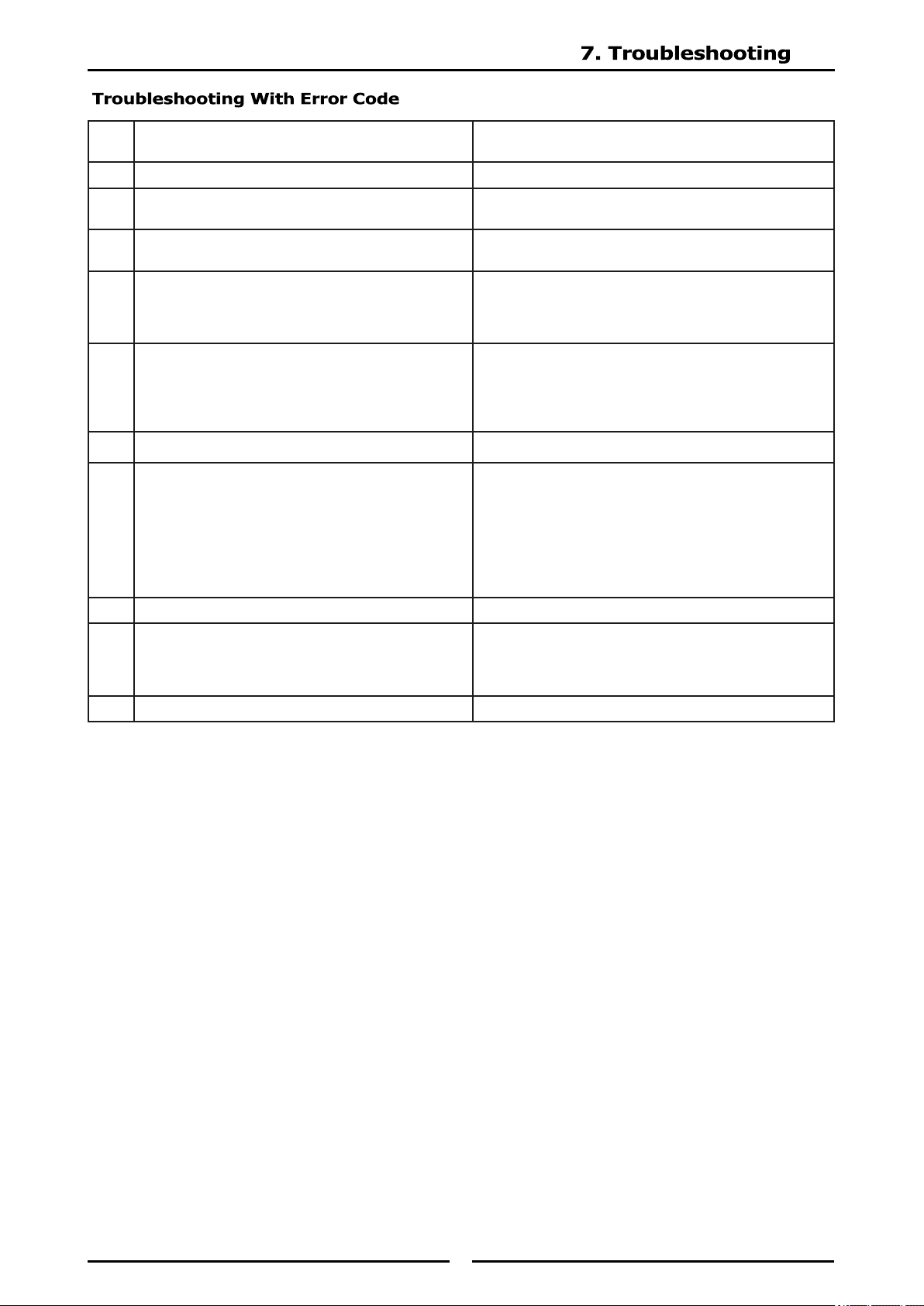
(2) The appliance switches off immediately.
Blink
Code
Problem Action
Normal Operation Normal Operation
1
Unsuitable induction cooking pan.
Internal wiring/coil connection malfunction. (2)
Check pan material.
Contact an authorized service agency.
2
Unsuitable induction cooking pan.
Coil overcurrent. (2)
Check pan material.
Contact an authorized service agency.
3
Air-cooling system obstructed.
Fan malfunction.
Heat sink overheated. (2)
Let appliance cool down.
Verify that air vents are not obstructed.
Check and clean air filter.
Contact an authorized service agency.
4
Overheated cook zone.
Overheated pan detected.
Sensor failure.
Let appliance and/or pan cool down. Check pan
material.
Verify that air vents are not obstructed.
Check and clean air filter.
Contact an authorized service agency.
5 Potentiometer defective. Contact an authorized service agency.
6
Ambient temperature too high (the cooling sys-
tem is not able to keep the induction appliance
in normal operating conditions).
Internal component overheated. (2)
Let appliance cool down.
Verify that air vents are not obstructed.
Check and clean air filter.
Verify that no hot air is taken in by the fan.
Reduce the ambient temperature.
The intake air temperature must be lower than
40°C [104°F].
Contact an authorized service agency.
7 Generator component failure. (2) Contact an authorized service agency.
8
Sensor error from heat sink.
Ambient temperature beyond normal operating
range. (2)
Verify that air vents are not obstructed.
Check and clean air filter.
Reduce ambient temperature.
Contact an authorized service agency.
10 Communication problem of the CAN interface Contact an authorized service agency.
32
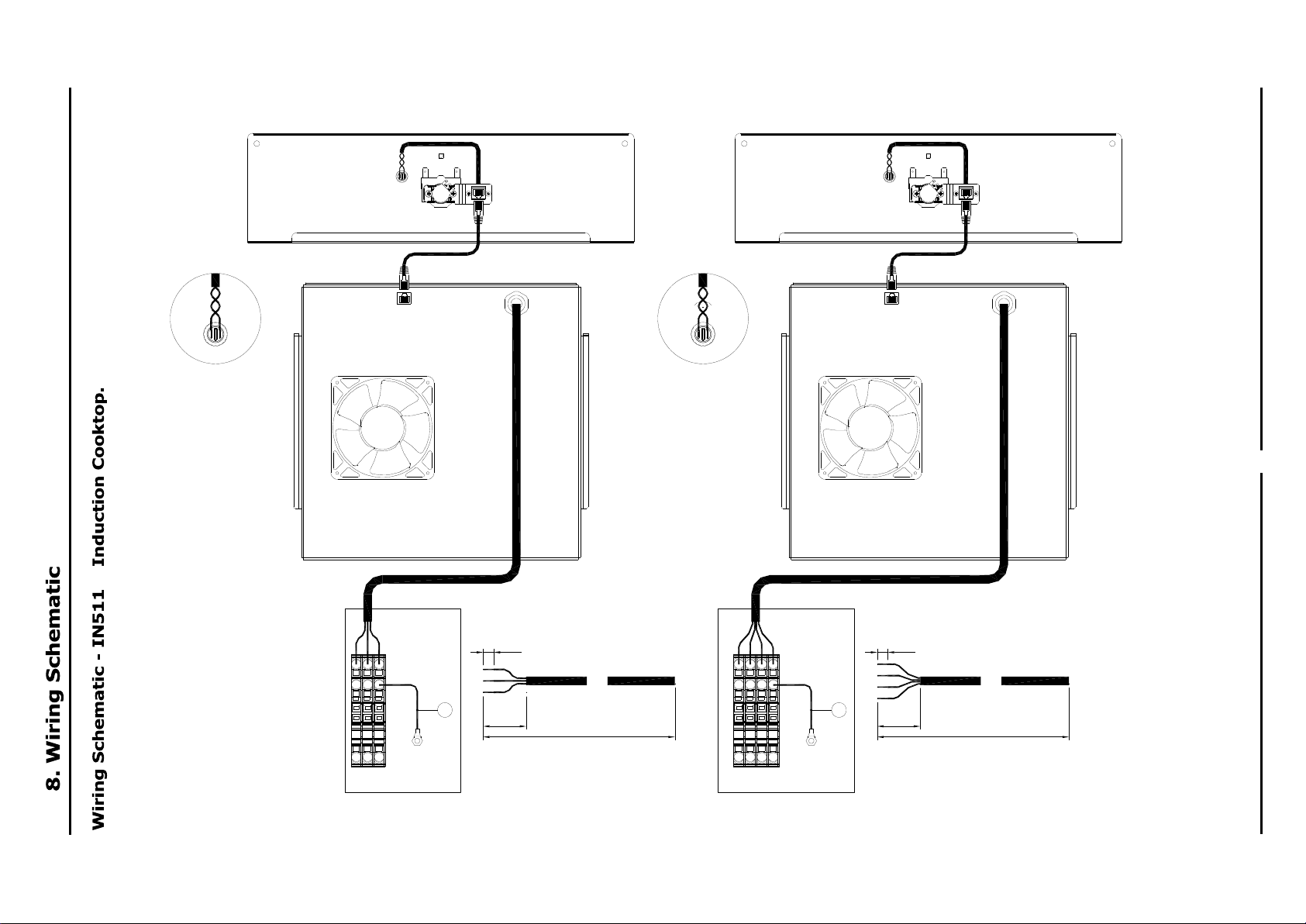
L1 N
PE
L1 L2 L3 PE
3.5kW SINGLE PHASE SINGLE COIL / WOK 5.0kW 3 PHASE SINGLE COIL / WOK
CUT POWER CABLE TO 1000mm LONG
REMOVE 100mm OF OUTER SHEATH
STRIP 15mm OF INSULATION FROM EACH WIRE
15
100
1000
15
100
1000
CUT POWER CABLE TO 1000mm LONG
REMOVE 100mm OF OUTER SHEATH
STRIP 15mm OF INSULATION FROM EACH WIRE
EARTH STUD EARTH STUD
FIT RJ45 CABLE (SUPPLIED WITH INDUCTION)
TO CONTROL AND GENERATOR
FIT RJ45 CABLE (SUPPLIED WITH INDUCTION)
TO CONTROL AND GENERATOR
CONNECT CONTROL WIRES
(GRAY / VIOLET) TO LED (1)
CONNECT CONTROL WIRES
(GRAY / VIOLET) TO LED (1)
1
1
248431 2.5mm² GRAY x 1
248432 2.5mm² BLUE x 1
248433 2.5mm² PE x 1
248434 2.5mm² END PLATE
248449 MARKER L1
248452 MARKER N
248453 MARKER PE
248439 10mm² GRAY x 3
248441 10mm² PE x 1
248442 10mm² END PLATE
248449 MARKER L1
248450 MARKER L2
248451 MARKER L3
248453 MARKER PE
33
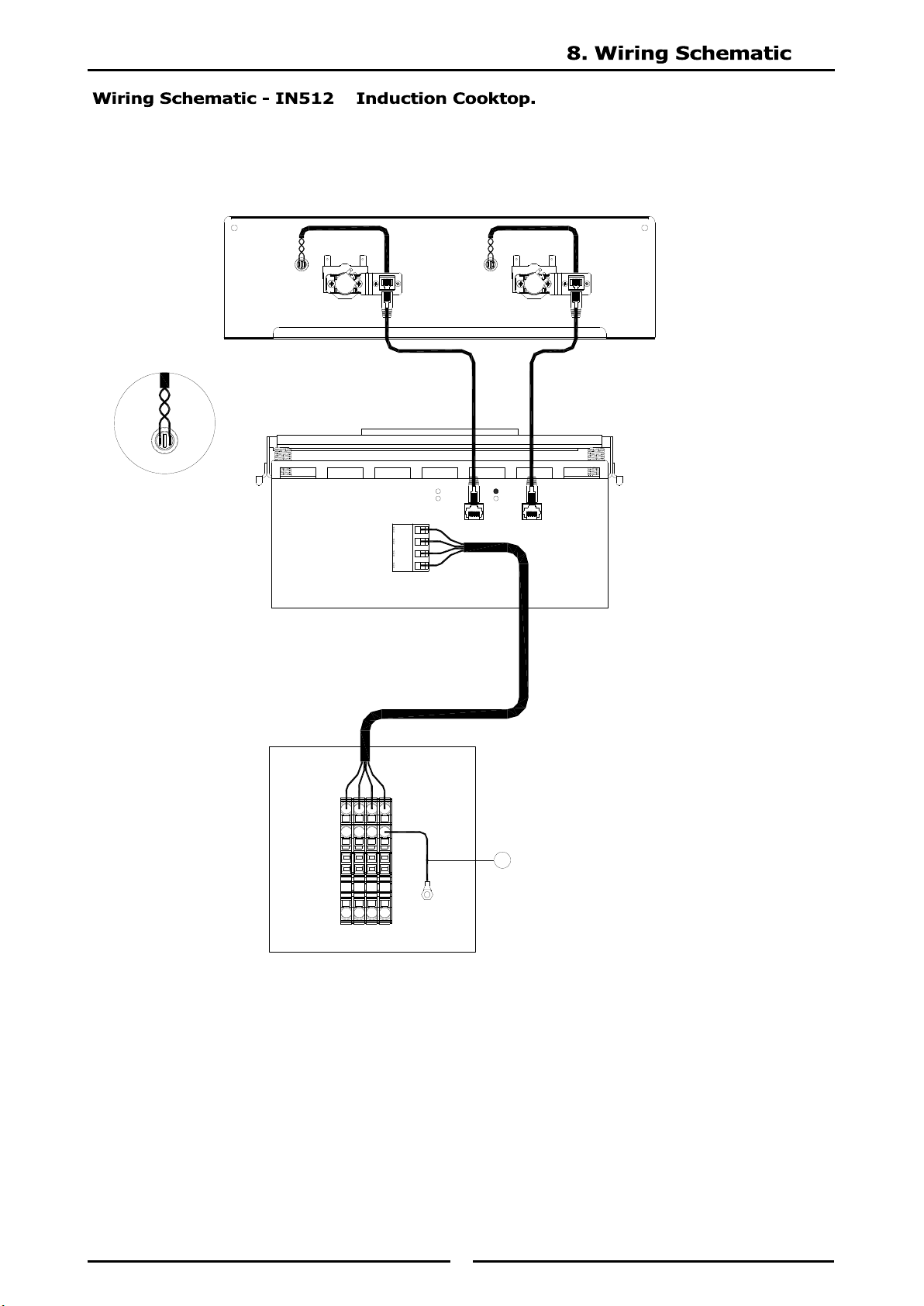
L1 L2
L3 PE
3.5 / 5.0kW 3 PHASE TWO COILS
L1
L2
L3
PE
Control
F1
Control
F2
FRONT REAR
248362 GENERATOR CONNECTION CABLE SHORT
EARTH STUD
FIT RJ45 CABLE (SUPPLIED WITH INDUCTION)
TO CONTROLS AND GENERATOR
CONNECT CONTROL WIRES
(GRAY / VIOLET) TO LED'S (2)
1
248439 10mm² GRAY x 3
248441 10mm² PE x 1
248442 10mm² END PLATE
248449 MARKER L1
248450 MARKER L2
248451 MARKER L3
248453 MARKER PE
34
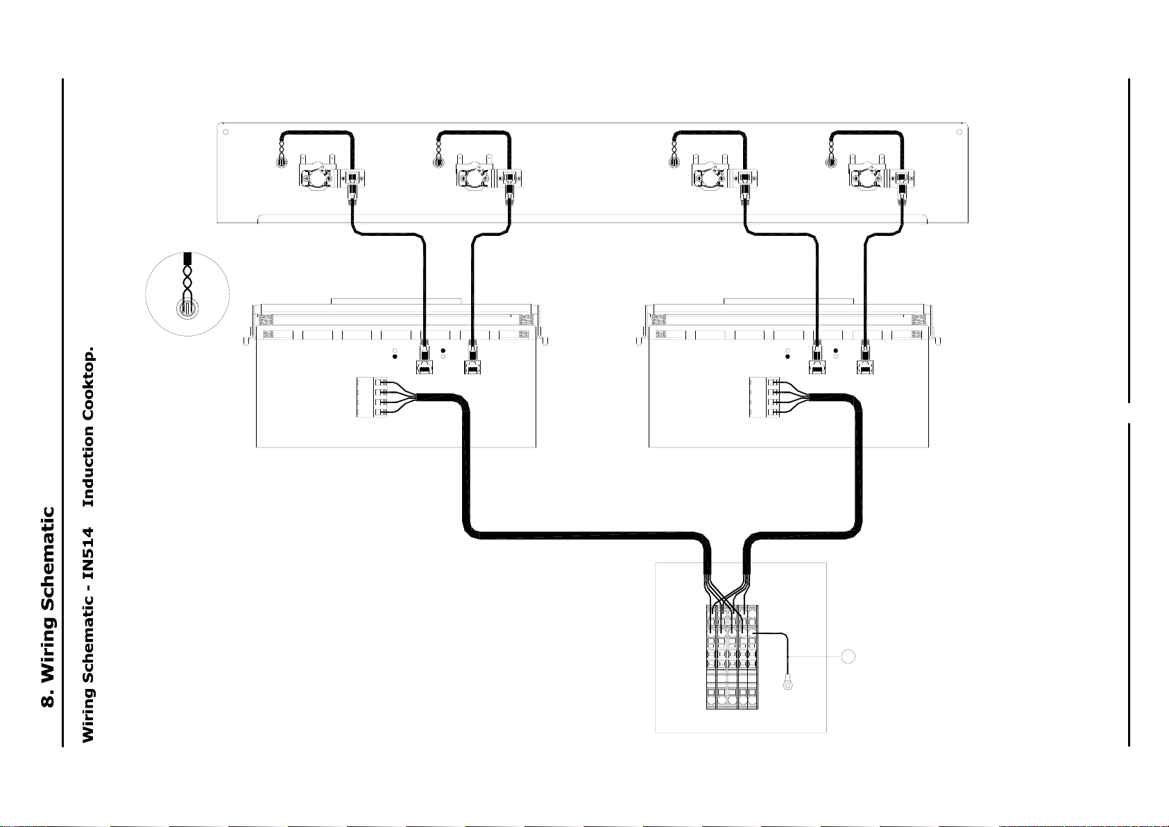
L1 L2 L3 PE
L1
L2
L3
PE
Control
F1
Control
F2
FRONT REAR
3.5 / 5.0kW 3 PHASE FOUR COILS
L1
L2
L3
PE
Control
F1
Control
F2
FRONT REAR
248362 GENERATOR CONNECTION CABLE SHORT248421 GENERATOR CONNECTION CABLE LONG
EARTH STUD
FIT RJ45 CABLE (SUPPLIED WITH INDUCTION)
TO CONTROLS AND GENERATORS
CONNECT CONTROL WIRES
(GRAY / VIOLET) TO LED'S (4)
1
248439 10mm² GRAY x 3
248441 10mm² PE x 1
248442 10mm² END PLATE
248449 MARKER L1
248450 MARKER L2
248451 MARKER L3
248453 MARKER PE
35
Replacement Parts List
When ordering replacement parts, please quote part number and description as listed below. If the part
required is not listed below, request the part by description and quote model number and serial number
which is shown on the appliance Rating Plate.
IMPORTANT:
Only genuine authorized replacement parts should be used for servicing and repair of
this appliance. Instructions supplied with parts should be followed when replacing
components.
For further information and servicing instructions, contact your nearest authorized
service branch (contact details are as shown on reverse of front cover of this manual).
247938 INDUCTION GLASS 360 X 360 1 ZONE ROUND
247939 INDUCTION GLASS 375 X 650 2 ZONE ROUND
248199 INDUCTION GLASS 360 X 360 1 ZONE FULL AREA
248200 INDUCTION GLASS 375 X 650 2 ZONE FULL AREA
247925 INDUCTION MODULE ROUND 1 X 3.5KW 230V 1PH
247926 INDUCTION MODULE ROUND 1 X 5KW 400V 3PH
247927 INDUCTION MODULE FULL AREA 1 X 5KW 400V 3PH
247928 INDUCTION MODULE ROUND 2 X 3.5KW 400V 3PH
247929 INDUCTION MODULE ROUND 2 X 5.0KW 400V 3PH
247930 INDUCTION MODULE FULL AREA 2 X 5KW 400V 3PH
244401 AIR FILTER SCREEN 450
248526 INDUCTION POTENTIOMETER CTRL TERMINATED
248234 INDICATOR LED 10MM GREEN 4.8QC 24V
248203 KNOB BLUE SEAL 6MM LO 1-10 HI INDUCTION
227855 LEG 80mm
227850 LEG 150mm (FLUSH STUD)
229674 REAR ROLLER ASSEMBLY
227856 MAGNET CATCH