Loading ...
Loading ...
Loading ...

9
ENGLISH
Trigger Switch/Reversing Button (Fig.A, J)
1. The tool is switched ON and OFF by squeezing and
releasing the trigger switch
1
.
2. A forward/reverse control button
2
determines the
direction of the auger bit
6
and also serves as a lock
offbutton.
3. To select forward rotation, release the trigger switch and
depress the forward/reverse control button to the left.
4. To select reverse, depress the forward/ reverse control
button the opposite direction.
NOTE: The center position of the control button locks the
tool in the off position. When changing the position of the
control button, be sure the trigger is released.
Proper Hand Position (Fig. I)
WARNING: To reduce the risk of serious personal injury,
ALWAYS use proper hand position as shown.
WARNING: To reduce the risk of serious personal
injury, ALWAYS hold securely in anticipation of a
suddenreaction.
Proper hand position requires one hand on the main
handle
3
, with the other hand on the side handle
4
to
control the twisting action of thetool.
Installing and Removing the Battery Pack
(Fig.H)
WARNING: Ensure the tool/appliance is in the off
position before inserting the batterypack.
NOTE: For best results, make sure your battery pack is
fullycharged.
1. To install the battery pack
1
into the tool handle, align
the battery pack with the rails inside the tool’s handle
and slide it into the handle until the battery pack is firmly
seated in the tool and ensure that it does notdisengage.
2. To remove the battery pack from the tool, press the
release button
11
and firmly pull the battery pack out of
the tool handle. Insert it into the charger as described in
the charger section of thismanual.
OPERATION
WARNING: To reduce the risk of serious personal
injury, turn unit off and remove the battery pack
before making any adjustments or removing/
installing attachments or accessories. An
accidental start‑up can causeinjury.
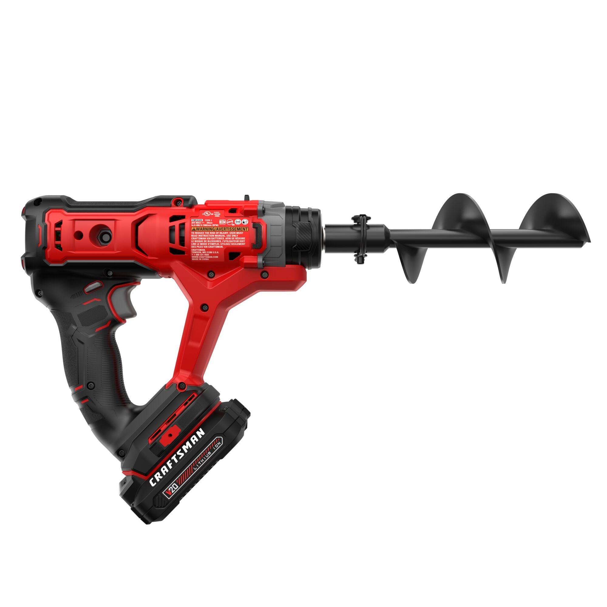
Installing and Removing the Auger Bit or
Other Tool Specific Accessory (Fig.F, G)
WARNING: Always lock off trigger switch
and disconnect tool from power source when
changingacces sories.
WARNING: Always ensure the auger bit is secure
before starting the tool. A loose auger bit may eject
from tool causing possible personalinjury.
WARNING: Check to be sure the accessory is straight
before installing onto the tool. A bent accessory can
create a hazardous imbalance or can move in a way to
create a hazardous condition.
To insert an auger bit
6
or other accessory, follow
thesesteps.
1. Turn tool off and remove batterypack.
2. Unlock the pin snap
8
and remove the lock pin
7
from
the auger bit
6
.
3. With one hand secure the tool. With the other hand
grasp the auger bit
6
and install the auger bit sleeve
9
onto the drive shaft
13
as shown in Fig. Z.
4. Rotate the auger bit to align the holes
14
on the
auger bit sleeve
9
and drive shaft
13
.
5. Insert the lock pin
7
through the auger bit sleeve
9
and
drive shaft
13
holes
14
.
6. Lock the lock pin
7
in position with the pin snap
8
.
Side Handle (Fig.E)
WARNING: To reduce the risk of personal injury,
ALWAYS operate the tool with the side handle properly
installed. Failure to do so may result in the side handle
slipping during tool operation and subsequent loss of
control. Hold tool with both hands to maximizecontrol.
WARNING: Before using the tool, check that the side
handle is tightenedsecurely.
The side handle
4
threads into either side of the motor
housing and allows right or left hand use.
Installing the Side Handle (Fig.E)
WARNING: The side handle should always be used to
maintain control of the tool at alltimes.
1. Choose right or left hand use and insert the side
handle
4
into the side handle hole located on either side
of the motor housing
5
.
2. Lock the side handle
4
in place by securely tightening
the side handle
4
rotating it clockwise so that the side
handle
4
will notrotate.
3. To switch the location of the side handle
4
rotate the
side handle counterclockwise until it is free from the
motor housing. Move the side handle to the opposite
position and reinstall as described above.
ASSEMBLY AND ADJUSTMENTS
WARNING:
To reduce the risk of serious personal
injury, turn unit off and
remove the battery pack
before making any adjustments or removing/
installing attachments or accessories. An accidental
start‑up can causeinjury.
7. To remove the auger bit, repeat steps 1and 2above.
Secure the tool with one hand. With the other hand
grasp the auger bit
6
and pull the auger bit from the
drive shaft
13
.
Loading ...
Loading ...
Loading ...
