This pacakge contains information you need to install and
use your product. Keep the package for future reference.
Instruction
Package
048-MS-12 series
048-MS-18 series
048-MS-24 series
048-MS-36 series


Installation Guide Contents
Warning and Safety -------------------------------------------------------------------------
Installation Information -------------------------------------------------------------------
Name of Parts --------------------------------------------------------------------------------
Pre-installation --------------------------------------------------------------------------------
Indoor Unit Installation --------------------------------------------------------------------
Outdoor Unit Installation ------------------------------------------------------------------
Check List ---------------------------------------------------------------------------------------
Test Run -----------------------------------------------------------------------------------------
Finishing Touch -------------------------------------------------------------------------------
05
07
09
11
12
18
23
23
24
Operation Manual Contents
Warning and Safety -------------------------------------------------------------------------
Product Specication ----------------------------------------------------------------------
Parts Details -----------------------------------------------------------------------------------
Remote Control -------------------------------------------------------------------------------
Operation Instructions ---------------------------------------------------------------------
Wi- / App Connection --------------------------------------------------------------------
Care and Maintenance --------------------------------------------------------------------
Troubleshooting ------------------------------------------------------------------------------
Disposal Guideline ---------------------------------------------------------------------------
26
28
32
33
35
46
52
54
57

4
Installation Guide
This guide contains all the information
you need to install your product.
Installation
Guide
048-MS-12 series
048-MS-18 series
048-MS-24 series
048-MS-36 series

5
v.03062023
Warning and Safety
*Read this guide before installation. Failure to follow the safety instructions may result in property
damage, serious injury, or death.
• The air conditioner is pre-charged with R32 refrigerant. Handle the air conditioner with care
and check if there is any refrigerant leakage during installation. Refrigerants have no odor
and can be toxic and ammable. Rapid evaporation of refrigerant may cause frostbite,
cardiac arrhythmia, and/or irritation, as well as cause environmental damage.
• The room for the installation, use, repair, and/or storage of this air conditioner should be
greater than 5m².
• Do not charge air conditioner refrigerant more than 1.7kg.
• Stop valve cover must be installed on the air conditioner to prevent possible refrigerant
leaks.
• Refrigerant leakage or damaged pipeline must be inspected and repaired by a qualified
HVAC technician.
• Do not install or store this appliance in a room with continuously operating ignition sources
such as open flames, gas appliances, or electric heater
• Do not install the appliance within 50cm of ammable substances such as alcohol, etc. Or
pressurized containers such as spray cans.
• The appliance must be installed in accordance with applicable federal, state, and local
regulations.
• Ensure that the power supply voltage corresponds to that stamped on the rating plate.
• Do not bend, tug, or compress the power cord during installation to prevent damaging the
power cord. The electrical cord should be replaced by a qualied electrician.
• Do not use power extensions and/or muti-socket modules for appliance installation.
• Do not alter, change, or modify the appliance.
• A fuse or overload protection device with a suitable capacity for the indoor unit must be
installed.
• The appliance must be tted with means for disconnection from the main power supply
under over-voltage category III conditions. All electrical wiring must follow federal, state, and
local regulations.
• Do not place the appliance in contact with water. The electrical insulation could be damaged
and thus cause electric shock.
• When working on the electric terminals, make sure the appliance is disconnected from the
power supply.
• Make sure the appliance is properly grounded to prevent electric shock.
• Store the air conditioner in a safe location to prevent possible damage before installation.
DANGER WARNING
WARNING
CAUTION
Indicates an imminently
hazardous situation that, if not
avoided, will result in death,
serious injury, or serious
property damage.
Indicates a potentially
hazardous situation that, if not
avoided, will result in death,
serious injury, or serious
property damage.
Indicates a potentially
hazardous situation that, if not
avoided, will result in minor to
moderate injury. It may also
be used to indicate unsafe
practices.

6
Installation Guide
Warning and Safety
• Prevent children from accessing the working area during installation to prevent
unforeseeable accidents.
• The base of the outdoor unit must be rmly xed.
• Carry out a test run after the installation.
• Installing a mini split AC requires specialized training and equipment. Hire a licensed
professional if not familiar with electrical wiring and HVAC systems.
• The packaging materials are recyclable and should be disposed of in separate waste bins.
• The appliance should not be installed in a location where the air outlet of the indoor or
outdoor units is obstructed. Obstructions of these openings may cause damage or failures
to the appliance.
CAUTION

7
v.03062023
Installation Information
Power Cord Requirement
Cable Type
Outdoor Power Supply
Cable
H07RN-F / H05RN-F
Interconnection Cord
H07RN-F / H05RN-F
Power Cord Minimum Cross
Sectional Area (North America)
Appliance Amp (A) AWG
10 18
13 16
18 14
25 12
30 10
40 8
Power Cord Minimum Cross
Sectional Area (Other Regions)
Appliance Amp (A)
Nominal
Cross
Sectional
Area (mm²)
>3 and ≤6 0.75
>6 and ≤10 1
>10 and ≤16 1.5
>16 and ≤25 2.5
>25 and ≤32 4
>32 and ≤40 6
NOTE:
• Maximum current and product specications are located on the side panels of the unit.

8
Installation Guide
Installation Information
Torque Parameters
Pipe Size (mm)
Newton Meter
(N-M)
Ø6 / Ø6.35 15 - 25
Ø9 / Ø9.52 35 - 40
Ø12 / Ø12.7 45 - 60
Ø15.88 73 - 78
Ø19.05 75 - 80
Pipe Length and Additional Refrigerant
Piping Length Additional Refrigerant (R32) Charge
≤16.4ft
No additional refrigerant needed
16.4ft - 49.2ft
(≤12000 Btu)
20g/m
16.4ft - 49.2ft
(≥18000 Btu)
30g/m

9
v.03062023
Name of Parts
Refrigerant Valves
Control Box
with wiring diagram
Insulating Tape Wrap
Indoor Unit
Outdoor Unit
Wiring Terminal
with wiring diagram
Electrical Wire
Drain Hose
Refrigerant Pipe

10
Installation Guide
Name of Parts
Included Accessories
Tools needed (not included)
• Screw Driver
• Hole Saw Ø70mm
• Refrigerant Leak Detector / Liquid Leak
Detector
• Allen Wrench
• Spanner
• Torque Wrench
• Measuring Tape
• Spirit Level
• Stud Finder
• Thermometer
• Vacuum Pump
• Hollow Wall Anchors / Molly Bolts
• Wood Screws
• Wall Sleeve
• Floor Mounting Base Kit / Wall Mount Kit
• Ø25 Drainage Joint
Refrigerant Pipe
2x
Drain Hose
1x
Wall Cover
1x
Plasticine Putty
1x
Insulation Wrap
1x
Remote Control
1x
Mounting Plate
1x
Electrical Wire
2x

11
v.03062023
≥15cm / 5.9"
≥20cm / 3.9"
≥30cm / 11.8"
≥30cm / 11.8"
≥15cm / 7.9"
≥100cm / 39.4"
≥20cm / 7.9"
≥20cm / 7.9"
≥100cm / 39"
(From the closest
item underneath
the indoor unit)
Pre-installation
1
4
5
7
8
9
6
2
Choose the installation location.
Mount the indoor unit.
Placing the outdoor unit.
Vacuum Pumping.
Check List.
Test Run.
Drill wall hole and Install
mounting plate.
‣ Page 12
‣ Page 17
‣ Page 18
‣ Page 22
‣ Page 23
‣ Page 23
‣ Page 12,13
3
Connent the indoor unit.
• Connect the refrigerant
pipes.
• Connect the drain hose.
• Connect electrical wires.
Connect the outdoor unit.
• Connect the refrigerant
pipes.
• Connect electrical wires.
‣ Page 14
‣ Page 15
‣ Page 16
‣ Page 20
‣ Page 21

12
Installation Guide
Molly Bolt Wall StudWall WallMounting Plate Mounting Plate
Bolt Wood Screw
Hollow Drywall Wood Stud
Install Mounting Bracket
1. Locate the studs and electrical wires inside the wall. Then measure the indoor unit dimensions and
add the surrounding clearance space to determine the exact mounting location.
2. Use a spirit level to level the mounting plate on the wall. Then mark out the screw hole positions.
3. Drill holes in the wall, then insert wall anchors into the holes and afx the mounting plate to the
wall using screws.
*Use a wood screw if the hole position is directly on a wood stud.
NOTE:
• You must use the correct wall anchor according to the type of the wall.
Picking a Indoor Unit Instalalltion Location
• Make sure the air inlet and outlet are clear of any obstruction.
• Condensation can be easily drained.
• All connections can be easily made to the outdoor unit.
• Indoor unit is out of children’s reach.
• Indoor unit is accessible for maintenance.
• Install 3m / 10ft away from TV or radio appliances.
(Radio interference may occur if appliances are placed too close to each other)
• Do not install in a laundry room or by a swimming pool.
• Ensure there is enough clearance space around the unit.
‣ Page 11
Indoor Unit Installation

13
v.03062023
Drill Wall Hole
NOTE:
• Make sure there is no building structure pillar, beam, strut, or any electrical wire, or water pipes in the way of the drill hole.
• Always insert the sleeve into the wall hole and seal the surrounding with putty if you are installing it on a hollow wall such as drywall
or plaster walls. This will prevent water, insects, or small animals from getting into the wall.
1. Pick 1 of the 3 piping positions on your air conditioner.
2. Mark a Ø70mm hole that goes from the indoor wall to the outdoor wall. The hole must be slanted
downward with a small angle. And the position of the hole must be lower than the indoor unit
drainage port.
3. Drill the hole and insert the wall sleeve (not included) and sleeve cover into the hole.
Right side of the unit
Piping Position
Left side of the unit
Indoor
5 - 10mm
Outdoor
Behind of the unit
• Drilling into electrical wires or water pipes inside the wall may cause electric shock, re, or
water damage.
WARNING
Indoor Unit Installation
Ø70mm hole

14
Installation Guide
Connect the Indoor Unit Refrigerant Pipes
NOTE:
• Carefully unroll the copper pipes and prevent kinking the pipes.
• Connection nuts must be tightened according to the torque requirement.
Hold
1. Position the pipes of the indoor unit towards the wall holes. Cut off and trim the plastic cover on
the unit if the pipes are positioned to the left or right side of the unit.
2. Unroll the included refrigerant pipes.
3. Remove the covers from the pipe ports and make sure the ports are clean and smooth.
4. Align the pipes to that from the indoor unit, then tighten the nut by hand.
5. Use a torque wrench to tighten the nut according to the requirement.
(Refer to installation information on .)
6. Wrap the joints with insulation tape.
‣ Page 08
Torque Tighten
Imperfect aring
Dirty pipes
Indoor Unit Installation
15
v.03062023
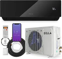
Connect the Indoor Unit Drain Hose
1. Adjust the drainage hose in the indoor unit.
* In some models, drainage ports are available on both sides of the indoor unit. You can choose
one side to attach the drain hose and insert a rubber plug on the unused port.
2. Connect the drain hose to the drainage port, make sure the joint is rmly connected and has a
good seal.
3. Wrap the joint with Teon tape to prevent any possible leak.
Drainage Ports
Drain Hose Installation
NOTE:
• Drain hose must be slanted
downward and leave a small gap
between the ground and the hose.
NOTE:
• Avoid having bends or dents on the drain hose.
• Do not leave the end of the hose into drainage gutter.
Indoor Unit Installation

16
Installation Guide
Connect the Indoor Unit Electrical Wires
1. Choose the right cable size according to your model's maximum operating current.
(Refer to installation information on .)
2. Open the front panel of the indoor unit.
3. Use a screwdriver to open the electric control box cover and get access to the terminal block.
4. Unscrew the cable clamp
5. Insert one end of the wires from the back of the indoor unit to the terminal block.
6. Connect the wires to the corresponding terminal.
*Detailed electrical diagram is printed on the control box cover.
7. Screw the cable clamp and secure the wires in place.
8. Reinstall the control box cover and close the indoor unit's front panel.
‣ Page 07
Terminal Block
Cable Clamp
Indoor Unit Installation
• Electrical wiring must be done by a qualied technician or electrician. Failing to connect the
wires correctly will cause short circuit, a re, and property damage.
WARNING

17
v.03062023
Mount the Indoor Unit
1. Carefully pass the pipes, hose, and cable bundle through the wall hole.
2. Hook the top of the indoor unit on the mounting plate.
3. Push the unit lightly left and right to make sure it is rmly hooked on the mounting plate.
4. Push down the bottom of the indoor unit and snap into the mounting plate.
Bundle the Pipes, Hose, and Wires
1. Arrange the pipes, hose, and wire cable according to the following image. Make sure the drain hose
is positioned at the bottom and avoid crossing or tangling any parts.
2. Wrap the bundle with Insulation tape.
Wire Cable
Refrigerant Pipe
Insulation Tape
Insulation Tape
Drain Hose
(Must positioned at the bottom)
After connecting the refrigerant pipes, electrical wires, and drain hose, they must be bundled with
insulating tape before passing them through the wall hole.
Indoor Unit Installation

18
Installation Guide
Placing the Outdoor Unit
Install Drainage Joint
• Do not install the outdoor unit near a heat source, steam, or ammable gas.
• Do not install the outdoor unit in windy or dusty locations.
• Do not install the outdoor unit in places where people often pass.
• Avoid installing the outdoor unit in places where it will be exposed to direct sunlight.
(If necessary, build a protection that does not interfere with the airow.)
• Make sure there is enough space around the outdoor unit to circulate air.
• Outdoor unit must be placed in a safe and solid location.
• The outdoor unit should ideally be placed on a concrete pad.
• Ensure there is enough clearance space around the unit.
‣ Page 11
1. Drainage joint (not included) is necessary for heating pump models.
2. Insert Ø25 drainage joint into the bottom hole of the outdoor unit.
3. Connect one end of the drain hose to the joint and the other end to the drainage point.
Outdoor Unit Installation
19
v.03062023
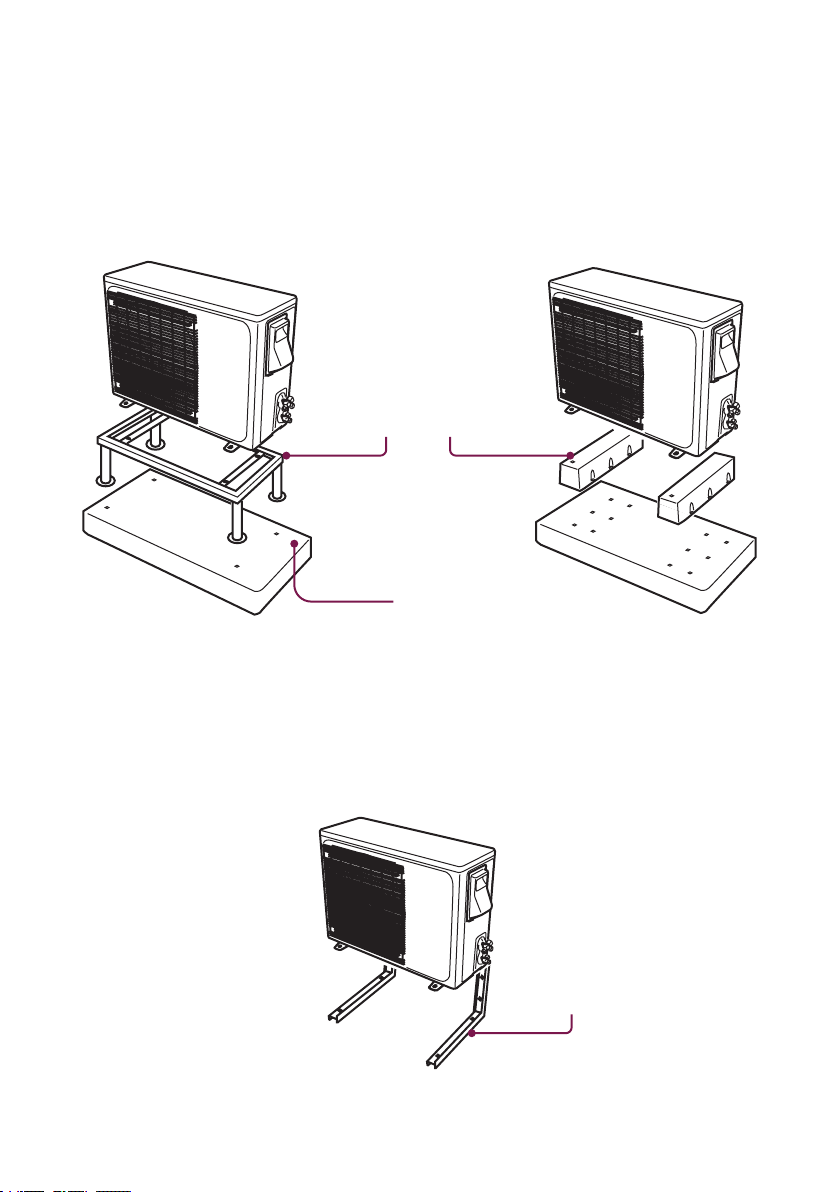
Secure the Outdoor Unit (Ground Installation)
Secure the Outdoor Unit (Wall Installation)
1. Place a concrete pad on the installation location.
2. Mount the outdoor unit in a base kit or stand.
3. Drill holes on the concrete pad.
4. Secure the base kit or stand on the concrete pad with concrete anchor bolts.
1. Measure the distance between the outdoor unit's legs.
2. Mount the wall mounting bracket on the wall.
3. Secure the outdoor unit on the wall mounting bracket.
NOTE:
• Rubber foot pads can be placed between the outdoor unit and the mounting kit to reduce vibrations and noise.
NOTE:
• The wall mounting bracket and the wall must be able to support at least 4 times the weight of the outdoor unit, or 441lb, whichever
is heavier.
The outdoor unit can be xed on a wall mounting bracket if there is no ground mounting option.
Wall Mount Bracket
(Not included)
Outdoor Unit Installation
Mounting Stand / Base Kit
(Not included)
Concrete Pad (Not included)

20
Installation Guide
1. Remove the plastic caps from the end of the valves.
2. Remove the covers from the pipe ports and make sure the ports are clean and smooth.
3. Align the pipes to the outdoor unit valve, then tighten the nut by hand.
4. Use a torque wrench to tighten the nut according to the requirement.
(Refer to installation information on .)
Connect the Outdoor Unit Refrigerant Pipes
‣ Page 08
Remove Plastic Caps
Hold
Torque Tighten
Outdoor Unit Installation

21
v.03062023
Connect Electrical Wire
Cable Clamps
1. Unscrew the screws from the wiring cover and remove it from the unit.
2. Unscrew the cable clamp.
3. Insert the electrical wires from the indoor unit through the opening on the cover, then connect the
wire to the outdoor unit terminal.
*Detailed electrical diagram is printed on the back of the wiring cover.
4. Insert power supply wires to the opening on the cover, then connect the wire to the outdoor unit
terminal.
*Detailed electrical diagram is printed on the back of the wiring cover.
5. Turn off any power from the power supply, and connect the wires to the power supply circuit box.
6. Reinstall the wiring cover to its original place.
NOTE:
• Both the wires from the indoor unit and from the power supply must be grounded.
Outdoor Unit Installation
Wire Terminal
Wiring Cover with
Electrical Diagram
Electrical Wires
from Indoor Unit
Electrical Wires
from Power Supply
22
Installation Guide
Outdoor Unit Installation
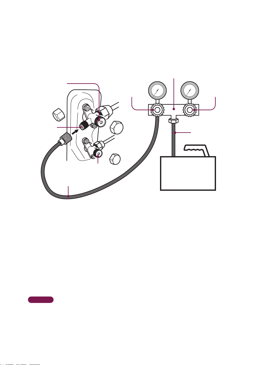
Vacuum Pumping and Leak Test
1. Remove the protective cap from the service port, low-pressure valve, and high-pressure valve.
2. Connect the pressure hose from the manifold gauge to the service port.
3. Connect the charge hose from the manifold gauge to the vacuum pump.
4. OPEN the low-pressure valve (Lo·M) and CLOSE the high-pressure valve (Hi·M) on the manifold
gauge.
5. Turn on the vacuum pump to vacuum the system.
6. Let the vacuum pump run for at least 15 minutes and make sure the gauge indicates −0.1Mpa
(−76cmHg).
7. Close the pressure valve (Lo·M) and turn off the vacuum pump.
8. Leave the system connected with the manifold gauge for 5 minutes, then make sure the gauge
indication does not exceed 0.005Mpa.
* In the case of a leak, and the pressure value increases, reconnect all the connection joints on the
refrigerant line, and redo the vacuum pumping.
9. Open the high-pressure valve (Hi·R) for 1/4 turn, then close the valve after 5 seconds.
10. Check all the connection joints with a refrigerant leak detector or liquid leak detector.
11. Add refrigerant charge if you use a lengthened refrigerant line.
12. Disconnect the pressure hose from the service port, then fully open the low-pressure valve (Lo·R)
and high-pressure valve (Hi·R).
13. Put the protective caps back on the service port, low-pressure valve, and high-pressure valve.
Tighten the caps.
‣ Page 08
High Pressure
Valve (Hi·M)
Low Pressure
Valve (Lo·M)
Low Pressure Valve
(Lo·R)
High Pressure Valve
(Hi·R)
Charge Hose
Service Port
Vacuum Pump
Pressure Hose
Manifold Gauge

23
v.03062023
Check List
Go through the following list and check your installation.
the checkbox for each conrmation.
Task List Status
Do the power supply and voltage match the unit rating ?
(Check before connecting to the power supply)
Is the electrical wiring in the air conditioner connected and secured ?
Is the air conditioner properly grounded ?
Is the power breaker, fuse, or protection device installed ?
Is the indoor mounting plate secured ?
Is the draining hose properly attached ?
Are the refrigerant pipes securely connected and no refrigerant leakage ?
Are all the pipes, hoses, and wires bundled and wrapped with insulation tape ?
Are the refrigerant valves fully opened ?
Can the remote control send control commands to the air conditioner ?
NOTE:
• Any failures, accidents, or damages caused by improper installation are not covered by the warranty.
Test Run
1. Turn on the power supply.
2. Turn on the air conditioner using the remote control.
3. Test the unit at the lowest temperature in COOL mode.
4. Test the unit at the highest temperature in HEAT mode.
5. Test each mode for at least 8 minutes.
- Measure the air temperature at the air outlet.
- Check if water drains properly from the drainage hose.
- Check if the louver and deectors move properly.
6. If everything is operating normally, return to the normal setting and turn off the air conditioner.
7. Inform the user to read the operation manual before use, and demonstrate to the user how to
use the air conditioner, the necessary knowledge of service and maintenance, and a reminder of
accessories storage.

24
Installation Guide
Finishing Touches
Seal the wall penetration with
sealant / putty / caulk etc. (not
included) to prevent water or
insects from getting into the
walls.
Install a decorative line cover kit
(not included) over the line bundle
to protect it from rain, sunlight, and
other external elements.
Complete the installation by sealing the opening in the wall and attaching a cover over the line bundle for
added protection..

Learn how to use and maintain this appliance
and troubleshoot.
Operations
Manual
048-MS-12 series
048-MS-18 series
048-MS-24 series
048-MS-36 series

26
Operation Manual
Warning and Safety
*Read this guide before installation. Failure to follow the safety instructions may result in property
damage, serious injury, or death.
• In the case of the appliance emitting smoke or burning smell, shut down the appliance and
disconnect from the power supply immediately.
• In the case of refrigerant leakage, shut down the appliance and disconnect from the
power supply. Contact a qualied technician for inspection. Refrigerant can be toxic and
ammable. Rapid evaporation of refrigerant may cause frostbite, cardiac arrhythmia, and/or
skin irritation.
• Cleaning and maintenance should be carried out by a specialized technician. The appliance
must be off and disconnected from the power supply before carrying out any maintenance.
• Do not disconnect the appliance from the power supply before shutting off the appliance.
This might create a spark and potentially cause a re.
• Repairs should be carried out by a professional or qualied technician only. Incorrect repair
could expose the user to potential electric shock or other kinds of hazards.
• Do not place ammable substances such as alcohol, etc. Or of pressurized containers such
as spray cans, or any other heat source near the appliance.
• Do not climb onto or place any objects on the appliance.
• Do not insert any objects into the appliance to prevent damage or injury.
DANGER WARNING
DANGER
WARNING
CAUTION
Indicates an imminently
hazardous situation that, if not
avoided, will result in death,
serious injury, or serious
property damage.
Indicates a potentially
hazardous situation that, if not
avoided, will result in death,
serious injury, or serious
property damage.
Indicates a potentially
hazardous situation that, if not
avoided, will result in minor to
moderate injury. It may also
be used to indicate unsafe
practice.

27
v.03062023
Warning and Safety
• If the appliance is used in areas without the possibility of ventilation, precautions must be
taken to prevent any leaks of refrigerant.
• Only use the appliance as instructed in this booklet. These instructions are not intended
to cover every possible condition and situation. As with any electrical household
appliance, common sense and caution are therefore always recommended for usage and
maintenance.
• This appliance is designed and made for air conditioning in domestic environments only. It
must not be used for any other purpose such as drying clothes or cooling foods.
• This appliance can be used by children 8 years old and above and persons with reduced
physical, sensory, or mental capabilities, or lack of experience and knowledge if they have
been given supervision or instruction concerning the use of the appliance in a safe way and
understand the hazard involved.
• Children shall not play with the appliance.
• Always use the appliance with an air lter. Using the appliance without an air lter would lead
to dust or waste accumulation or inner parts failure.
• Emptied remote control batteries must be recycled or disposed of properly.
• Do not touch the appliance when barefoot or parts of the body are wet or damp.
• Do not obstruct the air inlet or outlet.
CAUTION

28
Operation Manual
Product Specication
Model 048-MS-12K1VR-20S-JA 048-MS-12K2VR-17S-JA
Power Supply 115V / 60Hz / 1P 208V - 230V / 60Hz / 1P
Cooling Capacity 11,942BTU 11,942BTU
Heating Capacity 12,276BTU 12,276BTU
Dehumidifying Capacity 1 ℓ/h 1 ℓ/h
Rated Cooling Curret 9.2A 4.9A
Rated Heating Current 9.1A 5.1A
SEER rating 20 17.5
Indoor Unit Dimension
31.18” x 11.5” x 7.91” /
792 x 292 x 201 (mm)
31.18” x 11.5” x 7.91” /
792 x 292 x 201 (mm)
Outdoor Unit Dimension
27.76” x 10.98” x 20.87” /
705 x 279 x 530 (mm)
27.76” x 10.98” x 20.87” /
705 x 279 x 530 (mm)
Indoor Noise Level 41dBA 41dBA
Outdoor Noise Level 53dBA 54dBA
Indoor Unit Net Weight 8kg / 17.6lb 8kg / 17.6lb
Outdoor Unit Net Weight 21.5kg / 47.4lb 21.5kg / 47.4lb
Temperature Range 16°C - 32°C / 60°F - 90°F 16°C - 32°C / 60°F - 90°F
Environment Temperature
Range
−15°C - 48°C / 5°F - 118°F −15°C - 48°C / 5°F - 118°F
Suitable Area Up to 550sq.ft Up to 550sq.ft

29
v.03062023
Product Specication
048-MS-18K2V-17S-JA 048-MS-24K2V-17S-JA
048-MS-12K1VR-20S-
JPB
208V - 230V / 60Hz / 1P 208V - 230V / 60Hz / 1P 115V / 60Hz / 1P
18,005BTU 22,983BTU 11,942BTU
18,755BTU 23,979BTU 12,276BTU
1.6 ℓ/h 2.5 ℓ/h 1 ℓ/h
7.3A 9.0A 9.2A
7.3A 9.5A 9.1A
19 18.5 20
37” x 12.44” x 8.82” /
940 x 316 x 224 (mm)
44.57” x 13” x 9.13” /
1132 x 330 x 232 (mm)
31.18” x 11.5” x 7.91” /
792 x 292 x 201 (mm)
30.9” x 11.8” x 21.85” /
785 x 300 x 555 (mm)
32.48” x 25.78” x 12.2” /
825 x 655 x 310 (mm)
27.76” x 10.98” x 20.87” /
705 x 279 x 530 (mm)
47dBA 50dBA 41dBA
54dBA 58dBA 53dBA
11.5kg / 25.4lb 14kg / 30.9lb 8kg / 17.64lb
30kg / 66.1lb 43kg / 94.8lb 21.5kg / 47.4lb
16°C - 32°C / 60°F - 90°F 16°C - 32°C / 60°F - 90°F 16°C - 32°C / 60°F - 90°F
−15°C - 48°C / 5°F - 118°F −15°C - 48°C / 5°F - 118°F −15°C - 48°C / 5°F - 118°F
Up to 650sq.ft Up to 1500sq.ft Up to 550sq.ft

30
Operation Manual
Product Specication
Model
048-MS-12K2VR-17S-
JPB
048-MS-18K2V-17S-JPB
Power Supply 208V - 230V / 60Hz / 1P 208V - 230V / 60Hz / 1P
Cooling Capacity 11,942BTU 18,005BTU
Heating Capacity 12,276BTU 18,755BTU
Dehumidifying Capacity 1 ℓ/h 1.6 ℓ/h
Rated Cooling Curret 4.9A 7.3A
Rated Heating Current 5.1A 7.3A
SEER rating 17.5 19
Indoor Unit Dimension
31.18” x 11.5” x 7.91” /
792 x 292 x 201 (mm)
37” x 12.44” x 8.82” /
940 x 316 x 224 (mm)
Outdoor Unit Dimension
27.76” x 10.98” x 20.87” /
705 x 279 x 530 (mm)
30.9” x 11.8” x 21.85” /
785 x 300 x 555 (mm)
Indoor Noise Level 41dBA 47dBA
Outdoor Noise Level 54dBA 54dBA
Indoor Unit Net Weight 8kg / 17.6lb 11.5kg / 25.35lb
Outdoor Unit Net Weight 21.5kg / 47.4lb 30kg / 66.1lb
Temperature Range 16°C - 32°C / 60°F - 90°F 16°C - 32°C / 60°F - 90°F
Environment Temperature
Range
−15°C - 48°C / 5°F - 118°F −15°C - 48°C / 5°F - 118°F
Suitable Area Up to 550sq.ft Up to 650sq.ft

31
v.03062023
Product Specication
048-MS-12K2VR-21S-QC 048-MS-18K2VR-21S-QC 048-MS-24K2VR-21S-QC
208V - 230V / 60Hz / 1P 208V - 230V / 60Hz / 1P 208V - 230V / 60Hz / 1P
12,000BTU 17,000BTU 22,000BTU
12,000BTU 17,000BTU 23,000BTU
1 ℓ/h 1.6 ℓ/h 1.8 ℓ/h
4.3A 6.3A 7.8A
4.2A 6.2A 7.2A
21 21 21
29.96” x 11.61” x 7.87” /
761 x 295 x 200 (mm)
37.8” x 12.44” x 8.74” /
960 x 316 x 222 (mm)
42.87” x 12.91” x 8.94” /
1089 x 328 x 227 (mm)
27.76” x 10.98” x 20.87” /
705 x 279 x 530 (mm)
30.9” x 11.8” x 21.85” /
785 x 300 x 555 (mm)
35.43” x 27.56” x 14.17” /
900 x 700 x 360 (mm)
41dBA 49dBA 50dBA
52dBA 54dBA 59dBA
8kg / 17.6lb 11.58kg / 25.4lb 14kg / 30.9lb
24kg / 52.9lb 28kg / 61.7lb 43kg / 94.8lb
16°C - 32°C / 60°F - 90°F 16°C - 32°C / 60°F - 90°F 16°C - 32°C / 60°F - 90°F
−20°C - 60°C / −4°F - 140°F −20°C - 60°C / −4°F - 140°F −20°C - 60°C / −4°F - 140°F
Up to 550sq.ft Up to 650sq.ft Up to 1500sq.ft

32
Operation Manual
Parts Details
Display
• Indicator for the temperature setting.
NOTE:
• The graphical representation might have slight differences than the actual product.
Front Panel
Air Filter Screen
‣ Page 52
Air oulet
Air deector and ap
ON / OFF Switch
‣ Page 45

33
v.03062023
HEALTH
Remote Control
‣ Page 39
‣ Page 40
‣ Page 38, 39
‣ Page 38
‣ Page 41
‣ Page 42 ‣ Page 43
‣ Page 42 ‣ Page 43
Front of Remote Control
Display
Power Button
Temperature
Adjustment Button
Temperature Unit
Button
Turbo Button
Sleep Button
Display Button
Timer Button
Fan Speed Button
Swing Buttons
Anti-F Button
Mode Button
ELE.H Button Health Button
Eco Button iCLEAN Button
• Displays the setting.
• Turn on / off the air
conditioner.
• Change temperature
or timer setting.
• Toggle between °C
and °F.
• Toggle Turbo function
on / off.
• Toggle Sleep function
on / off.
• Turn on / off the LED
display.
• Timer setting.
• Select fan speed.
• Control deectors &
louvers to direct air
ow.
• Toggle Anti-Fungus
function on / off.
• Select operation
mode (AUTO/COOL/
DRY/HEAT/FAN).
• Toggle Electric Heater
function on / off.
• Toggle health
functions on / off.
• Toggle ECO mode on
/ off.
• Toggle self cleaning
function on / off.
NOTE:
• Appearance of the display and function of the remote control might differ from some models.
• The shape and position of buttons and indicator of the remote control might differ from some models.
• Some models may not have all the functions listed above.
‣ Page 41
I FEEL Button
• I FEEL function
setting.

34
Operation Manual
To set or replace batteries.
Attention
1. Remove the back cover from the remote control.
2. Insert 2 AAA 1.5V batteries.
3. Reinstall the back cover.
• Do not use rechargeable batteries.
• Replace the old batteries with new ones of the
same type. Do not mix old and new batteries.
• Do not dispose battieries as unsorted municipal
waste.
Remote Control
Back of Remote Control
Remote Control Display
The remote control display shows your mode settings.
The backlight will turn on by pressing any button on the remote control and automatically turn off 10
seconds after the last input.
35
v.03062023
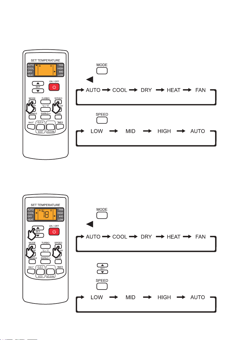
1. Press and select AUTO function.
- is pointed to AUTO on the display.
2. Press to change the air ow.
1. Press and select COOL function.
- is pointed to COOL on the display.
2. Press to set a temperature lower than the room temperature.
3. Press to change the air ow.
The cool function allows the air conditioner to cool the room and reduce
humidity.
Operation Instructions
Auto Mode
Cool Mode
The auto function allows the air conditioner to automatically adjust the
room’s temperature according to the programmed auto mode temperature.
HEALTH
HEALTH
NOTE:
• Temperature setting is not available in AUTO mode.

36
Operation Manual
Operation Instructions
The heat function allows the air conditioner to warm up the room.
Heat Mode
Dry mode allows the air conditioner to reduce the humidity of the air and
make the room more confortable.
Dry Mode
1. Press and select DRY function.
- is pointed to DRY on the display.
2. Press to set a temperature lower than the room temperature.
3. Press to change the air ow.
1. Press and select HEAT function.
- is pointed to HEAT on the display.
2. Press to set a temperature lower than the room temperature.
3. Press to change the air ow.
HEALTH
HEALTH
NOTE:
• The outdoor unit may defrost for 5-12 minutes before blowing heated air in cold weather.
37
v.03062023
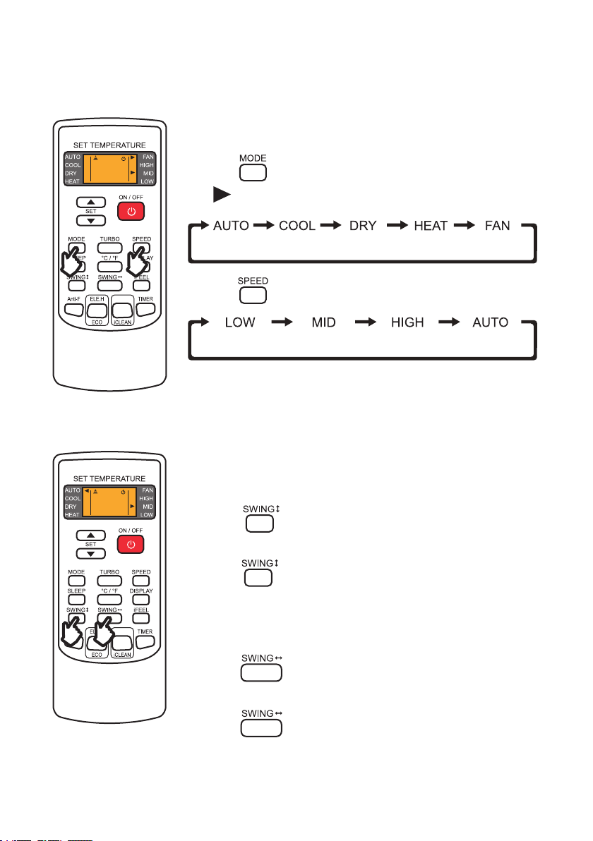
Operation Instructions
Fan Mode
1. Press and select FAN function.
- is pointed to FAN on the display.
2. Press to change the air ow.
HEALTH
Fan function circulates and ventilates air in the room.
Adjusting Air Flow
1. Press once to activate the horizontal louvers.
- Louvers will begin to swing.
2. Press to set desired position.
1. Press once to activate the vertical deectors.
-Deectors will begin to swing.
2. Press to set desired position.
Adjust horizontal louvers.
Adjust vertical deectors.
Adjusting up and down airow
Adjusting left and right airow
NOTE:
• Never manually adjust the louvers or the deectors. Attempt to move it by hand may damage
the moving mechanism.
HEALTH

38
Operation Manual
1. Turn off the unit.
2. Press once to set switch on timer.
- and are displayed on the remote display and the
“on” indicator ashes.
3. Press to set desired switch on time.
- The timer increases by half an hour between 0 - 10 hours and one
hour between 10 - 24 hours.
4. Press again to conrm the timer setting.
5. After setting the ON timer, press and to set desired
mode and fan speed.
6. Press to set desired operation temperature.
1. Press again cancel the ON timer.
Set a timer to automatically switch ON the air conditioner.
Operation Instructions
Timer
Setting ON Timer
Cancel ON Timer
NOTE:
• While ON timer is set, SLEEP, DISPLAY, and iFEEL buttons are not functional.
HEALTH

39
v.03062023
Operation Instructions
1. Press once to set switch off timer.
- and are displayed on the remote display and
the “off” indicator ashes.
2. Press to set desired switch off time.
- The timer increases by half an hour between 0 - 10 hours and one
hour between 10 - 24 hours.
3. Press again to conrm the timer setting.
1. Press again cancel the OFF timer.
Set a timer to automatically switch OFF the air conditioner.
Timer
Setting OFF Timer
Cancel OFF Timer
HEALTH
1. Press to activate turbo function.
- The fan speed will automatically change to HIGH.
2. Press again to deactivate turbo function.
Turbo function will speed up cooling or heating and blow the maximum ow
of air.
Turbo Function
HEALTH

40
Operation Manual
Operation Instructions
Sleep Function
1. Press once to activate SLEEP function.
- The air conditioner will operate under sleep function for 10 hours
before changing back to the previous setting mode.
2. Press again to disable sleep function.
Sleep function is a pre-set automatic operating program which is suitable
during sleep time.
Display Function
1. Press once to turn off the indoor unit display.
2. Press again to turn on the display.
Switch ON / OFF the LED display on the indoor unit front panel.
HEALTH
HEALTH
NOTE:
• Sleep function is not avaliable when the unit is operating in FAN mode.
41
v.03062023
Operation Instructions
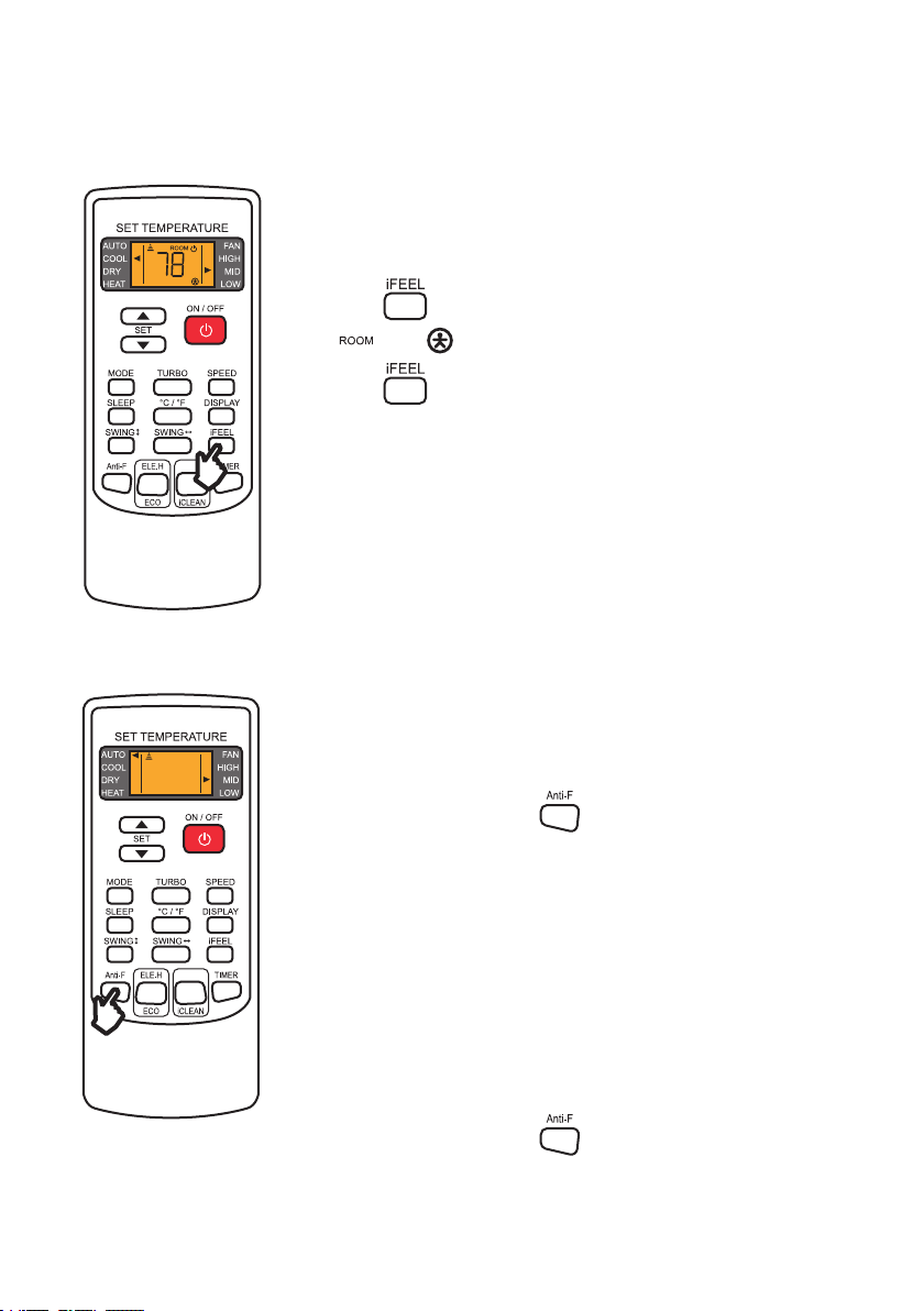
I FEEL Function
1. Press once to activate I FEEL function.
- and are displayed on the display.
2. Press again to disable I FEEL function.
I FEEL function turns your remote control into a portable thermostat that
automatically controls the unit to adjust the temperature of the room you
are in.
HEALTH
Anti-F Function
1. When the unit is off, press once to enable Anti-F function.
- The indoor unit beeps 5 times and the remote control display ashes
5 times indicating the Anti-F function is enabled.
2. The next time you turn off the air conditioner after using, the unit will
automatically operate in HEAT mode and low fan speed (FAN mode for
COOL only models) for about 3 minutes before fully turning off.
1. When the unit is off, press once to disable Anti-F function.
- The indoor unit beeps 3 times and the remote control display ashes
5 times indicating the Anti-F function is disabled.
Anti-F function will dry the internals of the indoor unit after you turn off the
air conditioner to prevent the growth of fungus or mold.
NOTE:
• When Anti-F function is operating, do not turn on the unit before it has completely turned off.
• Anti-F function is not functional when OFF timer is set.
Enable Anti-F Function
Disable Anti-F Function
HEALTH

42
Operation Manual
Operation Instructions
Eco Mode
ELE.H Function
1. When the unit is operating in HEAT mode, press once to turn
on electric heating.
2. Press again to disable ECO function.
1. When the unit is operating in COOL mode, press once to turn
on eco mode.
2. The air conditioner will operate in Eco mode for 8 hours and then goes
back to normal mode.
Switch ON / OFF electric heating on the unit.
The air conditioner will operate in the lowest electric comsumption for a
period of time.
HEALTH
HEALTH
NOTE:
• Changing operation mode or turning off the air conditioner will automatically cancels ECO
mode.
• The ECO mode only works for inverter models.
NOTE:
• This function is not available on North America models.
43
v.03062023
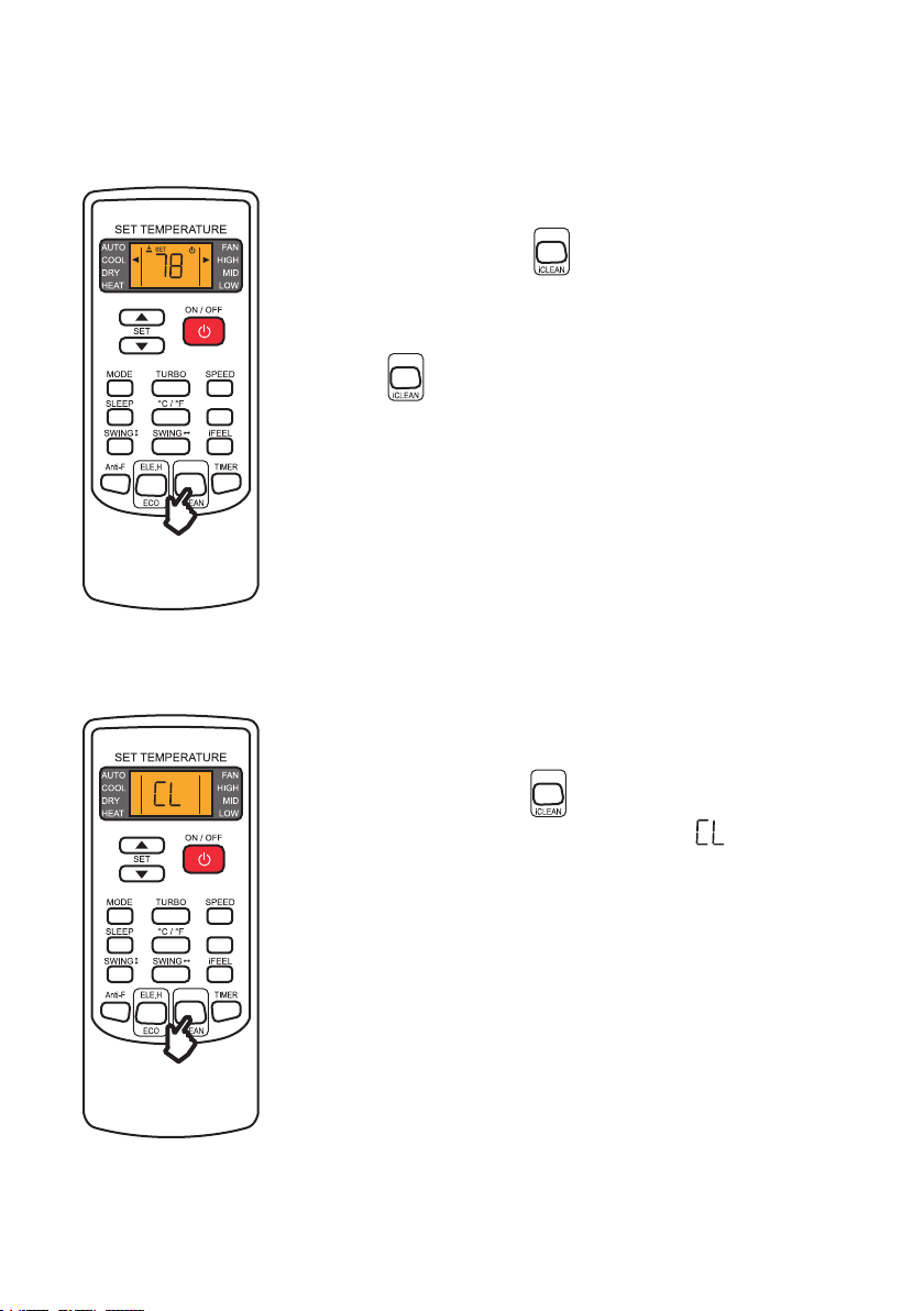
iCLEAN Function
Health Function
1. When the unit is on, press once to turn on health function.
- Health related function such as negative ion, electrostatic
precipitation, PM2.5 removal, etc, will be on depending on your actual
model.
2. Press again to disable health function.
1. When the unit is off, press once to turn on eco mode.
- The unit display and remote control will display and
automatically clean dust off the evaporator and dry it.
Switch ON / OFF health related function on the unit.
Switch ON / OFF the unit self cleaning function.
Operation Instructions
HEALTH
HEALTH
HEALTH
HEALTH
HEALTH

44
Operation Manual
Operation Instructions
Ambient Temperature
Operating Temperature
Your air conditioner may stop operating in the following temperature conditions.
You can set the air conditioner temperature within the following range.
NOTE:
• Attempting to use the air conditioner beyond the specied temperature range may activate the protection device and cause the air
conditioner to stop operating.
• When the temperature is too low, the heat exchanger of the air conditioner may freeze, leading to water leakage or other
malfunction.
• Prolong cooling or dehumidication in a humid environment may lead to water condensation or dripping near the air outlet.
• T1 and T3 refer to ISO 5151.
NOTE:
• Avoid prolonged exposure to cold air, especially to children, elderly, or medical patients.
COOL Mode HEAT Mode
Ambient Room
Temperature
< 64.4°F / 18°C > 80.6°F / 27°C
Outdoor
Temperature
T1 Climate: > 109.4°F / 43°C
< 19.4°F / –7°C
or
> 75.2°F / 24°C
T3 Climate: > 125.6°F / 52°C
Operation Temperature Setting
Remote Control
YKR-H/101E
YKR-H/102E
60°F - 90°F / 16°C - 32°C
Remote Control
YKR-H/132E
68°F - 82°F / 20°C - 28°C

45
v.03062023
Operation Instructions
Emergency Button
You can use the emergency button for limited control of the air conditioner in case the remote control
fails or is missing.
NOTE:
• Always wear insulation material when pressing the emergency button.
• In stand by mode, press this switch ONCE to start AUTO
mode.
• In operation, press this switch ONCE to turn off the unit.
Indoor unit ON/OFF switch

46
Operation Manual
Wi- / App Connection
NOTE:
• The Della+ application is free; however, data charges may apply when downloading or using the application.
• Every effort has been made to ensure the accuracy of the instruction and graphic representations at the time of producing this
user guide. Your application’s user interface, icons, and screen may look different from this guide due to updates and development
changes.
• Della+ app can be altered without notice for quality improvement and also be deleted depending on the circumstances of
manufacturing rms.
• Make sure you have a working Wi-Fi network.
• Connect your smart-phone to the Wi-Fi network.
• Wi-Fi network must support 2.4GHz, the appliance cannot connect to a
5GHz network.
• Search “DELLA+” on app store or google play, or scan the QR code
below to download the application.
• Enable permission of storage, location, and camera for this application,
otherwise it will have a problem operating.
Wi-Fi Network
Download the Application
Wi-Fi Requirement
Standards of WLAN
IEEE 801.11 b/g/n(channels 1-14)
Protocal Stack Support
IPv4 / IPv6 / TCP / UDP / HTTPS / TLS /
MulticaseDNS
Security Support
WEP / WPA / WPA2 / AES128
Network Type Support
STA / AP / STA+AP

47
v.03062023
Wi- / App Connection
Tap the country menu.
Tap the “Register” button
for rst time user.
Enter your email address,
then read and agree to the
user agreement, and get
verication code.
Open the DELLA+ app on
your smart devices.
Select your country.
1
4
2
5
3
User Registration

48
Operation Manual
Wi- / App Connection
Enter the verication
code.
Set your password and
tap “Done”.
76
User Registration

49
v.03062023
Wi- / App Connection
Add Device
Enter your Wi-Fi network
password, then tap “Next”.
You can see your device
on the device list after
adding.
Follow the in-app
instruction on adding the
device.
3 34
Select the appliance type you want to add by scanning the QR
above.
You can also nd the model series on the unit specication
label or on the packaging.
Tap “Add Device” in the
center of the screen or the
“+” dropdown menu from
the top right corner.
1 2
Specication Label
Model Series QR Code

50
Operation Manual
Wi- / App Connection
Basic Control
‣ Page 18
‣ Page 16
Temperature
Adjustment Button
Sleep Button
Function Button
Fan Button
Temperature Indicator
Mode Indicator
Schedule Button
Swing Button
Mode Button
• Change temperature
or timer setting.
• Sleep function setting.
• Access to more
functions.
• Select fan speed.
• Shows unit
temperature.
• Shows current mode.
• Set your ON/OFF
time.
• Control deectors
louvers to direct air
ow.
• Select operation
mode (AUTO/COOL/
DRY/FAN/HEAT).
The basic function of the application interface mimics to that of the remote control.
Power Button
• Turn on / off the air
conditioner.
NOTE:
• Some functions may not be avaliable on the application.
NOTE:
• Appearance of the display and function of the application might differ.
• The shape and position of buttons and indicator of the user interface might differ.

51
v.03062023
Wi- / App Connection
Scene
Tap “Create Scene” in the
center of the screen or the
“+” dropdown menu from
the top right corner.
Customize your unique
user experience.
21
“Scene” function allows you to program your air conditioner to turn on / off depending on your location,
and set automated features.

52
Operation Manual
Care and Maintenance
Clean the Unit
Clean the Air Filter
1. Clean the air conditioner with a soft dry cloth or a damped cloth with neutral detergent.
1. Open the front panel.
2. Pull down the air lter.
3. Clean the air lter with soapy water.
4. Air dry the air lter
5. Put the air lter back to its original place after it is dry.
NOTE:
• Do not ush the machine with water.
• Do not use volatile liquid such as thinner or alcohol to prevent damaging the unit.
NOTE:
• Do not touch the ns inside the indoor unit with bare hands after removing the lter screen.
• Check and clean the air lter regularly to prevent dust accumulation.
• Clean the air lter frequently if the operating environment is dusty or has bad air quality.
• Before cleaning the unit, you must shut down the machine and cut off the power supply for
at least 5 minutes.
• Never ush the air conditioner with water.
CAUTION
<113°F /
45°C

53
v.03062023
Care and Mainenance
Planning to not operate the air conditioner for a long period
Maintenance Routine
When Using the Air Conditioner After a Long Idle Period
1. Take out the batteries from the remote control and disconnect the power supply of the air
conditioner.
1. Clean the unit and the air lter screen.
2. Remove any obstacles at the air inlet and outlet of both the indoor and outdoor unit.
3. Make sure the drain pipe is unobstructed.
4. Install batteries into the remote control and connect the power supply to the air conditioner.
• Clean the air lter screen every 3 months.
• Call your HVAC technician to check on the refrigerant level every 3 to 4 years.
• Regularly check and remove any obstacles at the outdoor unit.

54
Operation Manual
Troubleshooting
Problem Possible Causes
The appliance is non operational
Power failure / plug pulled out
Damaged indoor or outdoor unit fan motor
Faulty compressor thermomagnetic circuit breaker
Faulty protective device or fuses
Loose Connection
Internal protection tripped
Outlet voltage does not match to that of the appliance
The unit is currently in ON-TIMER mode
Damaged electronic control board
Strange Odor Dirty air lter
Noise of running water Backow of liquid in the refrigerant circulation
A ne mist comes from the air outlet
This occurs when the air in the room becomes cold in COOL
or DRY modes
Strange noise
The noise made by thermal expansion of the front panel due
to temperature is normal and does not indicate a problem
Insufcient airow, either hot or cold
Unsuitable temperature setting
Obstructed air conditioner intakes and outlets
Dirty air lter
Fan speed is set at minimum
Other sources of heat in the room
Insufcient refrigerant levels
The appliance does not respond to
commands
Remote Control is too far away from the indoor unit
The batteries of the remote control need to be replaced
Obstacles between the indoor unit and the remote control

55
v.03062023
Troubleshooting
Problem Possible Causes
The display is off
DISPLAY toggle is set to off
Power failure
Indoor unit does not operate
immediately after a restart
Protective delay switch will delay the operation for 3 - 5
minutes if the air conditioner is turned on immediately after
it is turned off
• Strange noises during operation.
• Faulty electronic control board.
• Faulty fuses or switches.
• Spraying water or objects inside the appliance.
• Overheated cables or plugs.
• Very stong smells coming from the appliance.
Switch off the air conditioner immediately and cut off the power supply in the event of:
• Contact a professional HVAC technican for further assistance. Incorrect repairs may cause
electric shock, re, or permanant damage to the unit.
CAUTION

56
Operation Manual
In case of an error, the indoor unit display will show the following error codes:
Error Codes
Display Description
E0 Indoor Unit Overcurrent Protection
E1 Indoor Unit Temperature Sensor Error
E2 Outdoor Unit Coil Sensor Error
E3 Indoor Unit Coil Sensor Error
E4 Indoor Unit Fan Error
E5 (5E) Indoor and Outdoor Unit Communication Error
E8 Display Board and Main Control Panel Communication Error
F0 Outdoor Unit Fan Error
F1 Module Protection Error
F2 Power Factor Correction (PFC) board Error
F3 Compressor Out of Step Error
F4 Exhaust Sensor Error
F5 Compressor Top Head Sensor Error
F6 Outdoor Unit Temperature Sensor Error
F7
Overvoltage Protection (OVP) or
Undervoltage Protection (UVP) Error
F8
Outdoor Unit Control Panel and Module Panel
Communication Error
F9 Outdoor EEPROM Error
Troubleshooting

57
v.03062023
Disposal Guideline
This appliance contains refrigerant and other potentially hazardous materials. When disposing of the
appliance, follow all federal, state, and local regulations. DO NOT dispose of this product as normal
household waste or unsorted municipal waste.
When disposing of this appliance, you have the following options:
• Dispose of this appliance at a designated municipal electronic waste collection facility.
• When buying a new appliance, the retailer will take the old appliance.
• The manufacturer may take back the old appliance.
• Sell the appliance to a certied scrap metal dealer.
Display Description
FA Recirculated Sensor Error
P2 High Voltage Switch Protection
P3 Refrigerant Deciency Protection
P4 Refrigerant Overload Protection
P5 Exhaust Protection
P6 Indoor Unit High Temperature Protectino
P7 Anti-Freezing Protection
P8 Overcurrent Protection
Troubleshooting

58
Operation Manual
Memo

59
v.03062023

www.dellahome.com
800-863-4143
6:00a.m. – 4:00p.m. PST Monday - Friday
©Della All rights reserved.
Under the copyright law, this document may not
be printed, translated, reproduced, or distribute, in
whole or in part without written permission from
DELLA.
Every effort has been made to ensure that the
information in this document is accurate, DELLA is
not responsible for printing or clerical errors.
All trademarks, logo, brand names are the
property of their respective companies. Mention
of third-party products or service names are for
identification and informational purposes only.
Use of these names, brands, and trademarks
does not imply endorsement. DELLA assumes no
responsibility with regard to the performance or
use of these products.